EP1910038B1 - Marteau perforateur et/ou a percussion a entrainement lineaire et refroidissement a air - Google Patents
Marteau perforateur et/ou a percussion a entrainement lineaire et refroidissement a air Download PDFInfo
- Publication number
- EP1910038B1 EP1910038B1 EP06762834A EP06762834A EP1910038B1 EP 1910038 B1 EP1910038 B1 EP 1910038B1 EP 06762834 A EP06762834 A EP 06762834A EP 06762834 A EP06762834 A EP 06762834A EP 1910038 B1 EP1910038 B1 EP 1910038B1
- Authority
- EP
- European Patent Office
- Prior art keywords
- percussion
- hammer
- drive
- piston
- air
- Prior art date
- Legal status (The legal status is an assumption and is not a legal conclusion. Google has not performed a legal analysis and makes no representation as to the accuracy of the status listed.)
- Not-in-force
Links
Images


Classifications
-
- B—PERFORMING OPERATIONS; TRANSPORTING
- B25—HAND TOOLS; PORTABLE POWER-DRIVEN TOOLS; MANIPULATORS
- B25D—PERCUSSIVE TOOLS
- B25D17/00—Details of, or accessories for, portable power-driven percussive tools
- B25D17/20—Devices for cleaning or cooling tool or work
-
- B—PERFORMING OPERATIONS; TRANSPORTING
- B25—HAND TOOLS; PORTABLE POWER-DRIVEN TOOLS; MANIPULATORS
- B25D—PERCUSSIVE TOOLS
- B25D11/00—Portable percussive tools with electromotor or other motor drive
- B25D11/06—Means for driving the impulse member
- B25D11/064—Means for driving the impulse member using an electromagnetic drive
-
- B—PERFORMING OPERATIONS; TRANSPORTING
- B25—HAND TOOLS; PORTABLE POWER-DRIVEN TOOLS; MANIPULATORS
- B25D—PERCUSSIVE TOOLS
- B25D2216/00—Details of portable percussive machines with superimposed rotation, the rotational movement of the output shaft of a motor being modified to generate axial impacts on the tool bit
- B25D2216/0007—Details of percussion or rotation modes
- B25D2216/0015—Tools having a percussion-only mode
-
- B—PERFORMING OPERATIONS; TRANSPORTING
- B25—HAND TOOLS; PORTABLE POWER-DRIVEN TOOLS; MANIPULATORS
- B25D—PERCUSSIVE TOOLS
- B25D2217/00—Details of, or accessories for, portable power-driven percussive tools
- B25D2217/0011—Details of anvils, guide-sleeves or pistons
- B25D2217/0023—Pistons
Definitions
- the invention relates according to the preamble of claim 1 a drilling and / or percussion hammer with an electrodynamic linear drive.
- a drilling and / or percussion hammer with an electrodynamic linear drive is from the US-A-1 723 607 known.
- Drilling and / or impact hammers are usually driven by electric motors in which a rotor rotates a drive shaft.
- the rotor is usually coupled to a fan of a fan, which generates a cooling air flow. The rotational movement of the rotor is thus used in a simple manner for driving a radial or Axialltypicalerrades.
- An air spring impact mechanism is known in which a drive piston can be driven by an electrodynamic linear drive.
- the drive piston is coupled to a rotor of the linear drive, so that the linear reciprocating motion of the rotor is transmitted to the drive piston.
- the movement of the drive piston is transmitted via an air spring to a percussion piston, as is usual with air spring impact devices, which strikes against a tool end or an interposed anvil in a known manner.
- a percussion hammer which has a directly linear electrodynamically driven impact element.
- the impact element and a drive element form a functional unit and are rigidly or positively connected firmly.
- Chambers lying in front of and behind the impact or drive element are connected to themselves and to the ambient atmosphere via ducts.
- the hammer mechanism When the hammer mechanism is in operation, the volumes in front of and behind the impact element change in opposite directions. Due to the connection of both chambers, air is exchanged between the two chambers.
- the invention has for its object to provide a drilling and / or percussion hammer with an electrodynamic linear drive, in which a sufficient air cooling of the heat-generating components is ensured.
- An inventive hammer drill and / or percussion hammer (hereinafter referred to as hammer) has an air-conveying device with a linearly reciprocable pumping element for generating a cooling air flow.
- the pumping element is coupled to the drive element and / or the striking element of the percussion mechanism in such a way that the movement of the drive element and / or of the striking element can be transferred to the pumping element.
- the air conveying device has a pumping space and an air duct, wherein the pumping element can be moved back and forth in the pumping space and the pumping space can be brought into contact with the environment at least temporarily via the air duct.
- a type of air pump is formed, which functions similar to a bicycle pump (piston pump). Due to the coupling of the pump chamber with the environment via the air duct, there is the possibility that fresh cooling air can be supplied from the environment into the pump chamber or heated air can be released to the environment.
- the air channel has an intake passage for the inflow of. Air from the environment in the pump room. Accordingly, the air duct also has an outlet channel for the outflow of air from the pumping space into the environment. While in a variant not according to the invention the ambient air is conveyed back and forth in the air duct, when the air duct is divided into an intake duct and an exhaust duct a directional air flow can be achieved, which always flows only in one direction. Accordingly, cold air from the environment is supplied via the intake passage while the heated air is discharged to the environment via the exhaust passage.
- the drive element can, for. B. are formed by a drive piston in an air spring impact mechanism. It is reciprocated by the linear drive in a known manner. According to the invention, the pumping element is coupled to the drive element in an advantageous manner, so that it likewise has to reciprocate linearly. With the help of this oscillating linear movement, a cooling air flow can be generated, which is guided past the components to be cooled.
- the linearly driven air conveying device makes it possible to generate a cooling air flow without having to provide a rotary ventilator.
- the drive element is connected to a rotor of the linear drive.
- the drive element carries the rotor or is substantially completely formed by the rotor, so that the rotor simultaneously assumes the function of the drive element.
- the linear motor can be a switched reluctance motor (SR motor) and has several drive coils (stator) in the movement range of the rotor, which are switched according to the desired movement of the drive element.
- SR motor switched reluctance motor
- an electrodynamic drive z. B. is considered in the form of a single electromagnetic coil, which serves as a drive coil for the drive element.
- the return movement of the drive element can then z. B. via a coil spring o. ⁇ . respectively.
- Decisive is that the drive element is closely connected to the rotor.
- the coupling device has at least one between the drive element and the striking element effective stop.
- the stop ensures a positive transmission of the movement of the drive element to the striking element, which must then necessarily follow the movement of the drive element.
- the coupling device has an elastic element acting between the drive element and the striking element in at least one direction.
- the stop described above elastic, z. B. by a stopper held on the elastic element or an elastic coating.
- the elastic element may also be formed by a later explained air spring, when the percussion is realized as Luftfedertschwerk.
- the drive element, the rotor and the pumping element form a structural unit.
- these components can be integrally connected to each other, so that the movement of the rotor can be transferred lossless to the drive element and the pumping element.
- the drive element and the pumping element must then necessarily follow the movement of the rotor.
- the movement of the drive element via a mechanical, hydraulic or pneumatic coupling to the pumping element is transferable.
- a Bowden cable or a hydraulic line can run between the drive element and the pump element in order to transmit the movement of the drive element to the pump element with as little loss as possible.
- the pumping element can then also be arranged at a different location in the hammer.
- the pumping element is arranged in a region of the hammer which is decoupled from the impact mechanism in terms of vibration.
- the impact mechanism and the linear drive generate considerable vibrations due to the oscillating motion of the moving elements and the impact of the striking element.
- many approaches are known to reduce these vibrations z. B. to isolate from a handle of the hammer and to protect the operator from harmful vibrations. Accordingly, it is known in almost all hammers to decouple at least a portion vibrationally from the percussion.
- the arrangement of the pumping element in this vibration-decoupled region has the advantage that the pumping element and the remaining components of the air-conveying device are mechanically stressed less, so that a more reliable mode of operation can be achieved.
- the rotor is designed substantially cylindrical or hollow cylindrical. Alternatively, it may also have at least one axially extending plate-shaped or sword-like element. This plate-shaped element, the z. B. is formed as an extension on the drive element extends into the stator to achieve the desired drive effect.
- the air duct is arranged such that it runs along heat-generating components of the hammer, in particular along a part of a stator of the linear drive.
- the stator is traversed by an electric current and accordingly contributes significantly to the heat generation. This heat can be removed from the stator via the cooling air flowing through the air duct.
- a check valve is arranged in the intake duct and / or in the outlet duct, which permits an air flow only in one direction.
- a storage device which is in communicating connection with the outlet channel and serves for temporarily storing at least part of the air flowing out via the outlet channel.
- the storage device ensures a compensation of the air pressure fluctuations that inevitably arise due to the movement of the pumping element. Pressure peaks can be reduced by the fact that the storage device briefly absorbs air. If, on the other hand, no air is supplied by the pumping element, the storage device releases the air again and thus ensures a substantially uniform flow of cooling air.
- an elastic or spring-loaded element is provided in the storage device, which changes the size of a storage space as a function of the pressure of the air flow supplied by the pumping element.
- a cross section of the exhaust passage downstream of the storage device is smaller than a cross section of the exhaust passage upstream of the storage device. It is thus possible that the air flow conveyed by the pumping element can reach the storage device unhindered in order to fill the storage device with as little loss as possible. The actual cooling air flow is then discharged via the outlet channel of smaller cross-section, this outlet channel extending along the heat-generating components.
- a check valve can be arranged in the outlet channel between the pump chamber and the storage device.
- the pumping element is arranged in the direction of impact behind the drive element and the rotor.
- the pumping element can also be arranged next to the striking mechanism. It is desirable that the air pumping device must be arranged as space-saving as possible in the housing of the hammer in order not to increase the overall volume, especially the overall length.
- the striking mechanism is formed by an air spring impact mechanism.
- the drive element is designed as a drive piston and the impact element as a percussion piston, wherein the coupling device has a trained in a cavity between the drive piston and the percussion piston air spring.
- the air spring thus transmits in a known manner, the drive movement of the drive piston on the percussion piston.
- the coupling according to the invention of a linear drive with an air-conveying device can be applied to all types of striking mechanisms.
- the coupling according to the invention is suitable for percussion, which are designed as Heilfeder Farbwerke, and thus therefore known per se tube impactors (drive piston and percussion pistons with identical diameter), hollow piston impactors (drive piston with cavity in which the percussion piston moves) or drums with hollow percussion piston , in which the drive piston moves.
- the drive piston surrounds the percussion piston in the direction of impact before and behind the percussion piston such that the air spring is disposed behind the percussion piston and that before the percussion piston, a second air spring between the drive piston and the percussion piston can be formed ,
- this percussion type thus creates a double air spring, which on the one hand generates the movement of the percussion piston forward and on the other hand supports a return movement of the percussion piston.
- an effective for generating the air flow cross-sectional area of the pumping element is greater than acting on the air spring cross-sectional area of the drive piston.
- a significant heat output which must be dissipated.
- a correspondingly large cooling air flow is required.
- a correspondingly large cross-sectional area of the pumping element must be present.
- the pumping element can also be replaced by a plurality of individual pumping elements which, taken in themselves, are dimensioned smaller, but together achieve a sufficiently large effective cross-sectional area through their coupling with the rotor and thus their interaction together. Accordingly, the term “pumping element” refers only to the function, not to the specific embodiment.
- Fig. 1 to 8 show different embodiments of the hammer according to the invention in a greatly simplified sectional view.
- known per se components such.
- handles and electrical connections omitted, since they do not affect the invention.
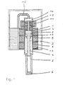
- Fig. 1 shows a first non-inventive embodiment with a driven by an electrodynamic linear actuator air spring impact mechanism.
- the air spring impact mechanism has as drive element a drive piston 1 which encloses a piston head 2 of a percussion piston 3 acting as a striking element.
- the percussion piston 3 extends with a shaft 4 in a percussion piston guide 5 and can strike in its foremost position against a tool end 6.
- an intermediate header can also be provided in a known manner.
- first air spring 7 acts between the drive piston 1 and the percussion piston 3, a cavity is formed, in which acts as a coupling device first air spring 7 acts.
- first air spring 7 acts in a forward movement of the drive piston 1, which is axially reciprocable in a percussion gear 8, a pressure builds up in the first air spring 7, which drives the percussion piston 3 to the front, so that it can finally strike against the tool end 6.
- a negative pressure which sucks the percussion piston 3.
- the return movement of the percussion piston 3 is also supported by the impact reaction at the tool end 6.
- a second air spring also serving as a coupling device is provided 9 formed, which comes into effect during the return movement of the drive piston 1. It also supports the return movement of the percussion piston 2.
- the oscillating, linear reciprocating movement of the drive piston 1 is effected by an electrodynamic linear drive.
- the drive piston 1 is coupled to a rotor 11 of the linear drive.
- the rotor 11 may be formed by a plurality of stacked electrical sheets and is reciprocated by alternating magnetic fields generated by a stator 12 of the linear drive.
- the operation of such a linear drive is known and z. B. in the DE 102 04 861 A1 described.
- the linear motor it may, for. B. may be a reluctance motor with external stator.
- the rotor 11 and the drive piston 1 form in the in Fig. 1 example shown a one-piece unit.
- a pumping element in the form of a pump piston 13 is formed, which is in a pumping chamber 14 back and forth. Since the pump piston 13 is integrally connected to the rotor 11 and the drive piston 1, the pump piston 13 must necessarily follow the movement of the rotor 11. As a result of the reciprocating movement, the pump piston 13 generates an overpressure or underpressure in the pumping chamber 14.
- the pumping chamber 14 communicates with the environment via an air channel 15.
- the air duct 15 is arranged to the hammer so that it is guided past at least a part of the heat-generating components (in this case in particular the stator 12), as in FIG Fig. 1 shown.
- the pump piston 13, the pumping chamber 14 and the air channel 15 form an air conveying device.
- the pumping element is shown cylindrically on the basis of the pumping piston 13.
- the pumping element can also take any other forms and z. B. be formed as a prismatic disc.
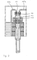
- Fig. 2 shows analogously to Fig. 1 a second embodiment of the invention. Identical components are identified by the same reference numerals. To avoid repetition, therefore, only the differences between the second and the first embodiment will be explained below.
- the air duct 15 is divided into an intake passage 15a and an exhaust passage 15b. Air from the environment can flow into the pumping chamber 14 via the intake duct 15a when the pump piston 13 moves downwards. In a return movement of the pump piston 13, the air is discharged from the pumping chamber 14 via the outlet channel 15b to the environment.
- an inlet check valve 16 is arranged in the intake passage 15a and an outlet check valve 17 is arranged in the outlet passage 15b.
- check valves 16, 17 are formed as spring-loaded balls.
- other types of check valves can be used.
- it will normally be sufficient to form the check valves by means of a rubber element attached on one side, which is lifted from a direction of a valve opening when it flows from one direction, while it is pressed in the reverse flow direction to the valve opening, and thereby closes.
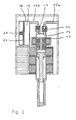
- Fig. 3 shows a third embodiment of the invention, which differs from the in Fig. 2 shown second embodiment differs in that in the region of the outlet channel 15b, a storage device 18 is provided.
- the memory device 18 is used to compensate for changes in air pressure, which inevitably arise in particular in the outlet channel 15b by the oscillating movement of the pump piston 13.
- the storage device 18 is able to eliminate pressure peaks by enlarging a storage space 19 against the action of a resilient element 20. As soon as the pumping pressure through the pump piston 13 decreases, the resilient element 20 causes a reduction of the storage space 19, so that an air flow through the downstream part of the outlet channel 15b is maintained.
- the elastic element 20 is designed as a helical spring which presses against a movable wall 21.
- this system can also z. B. be replaced by a rubber membrane.
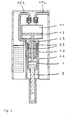
- Fig. 4 shows a fourth embodiment of the invention in analogy to the second embodiment of Fig. 2 .
- the traveler is constituted by two sword-like plate projections 22 which are reciprocable in a correspondingly shaped stator 12.
- the pump piston 13 is connected via a piston rod 23 with the drive piston 1 in connection.
- the cross-sectional area of the pump piston 13 and the pumping chamber 14 can be increased, since these components are arranged behind the linear drive.
- Fig. 5 shows a fifth embodiment of the invention, in which the air conveying device is arranged axially to save space next to the air spring impact mechanism.
- the pump piston 13 and the pumping chamber 14 enclose for this purpose the air spring impact ring annular.
- two or more pumping pistons 13 may be provided, which are movable in respectively associated pumping chambers 14.
- the function of the pump piston 13 can thus be achieved by a plurality of individual pistons.
- the outlet channel 15b is also guided past the stator 12, in which the rotor 13 with plate extensions is movable.
- FIG. 6 A sixth embodiment of the invention is shown, Here, the air pumping device with the pump piston 13 and the pumping chamber 14 is provided separately from the drive piston 1 and the rotor 11.
- a hydraulic piston 24 is formed, which via a hydraulic line 25 hydraulic fluid to a hydraulic shaft 26 which is connected to the pump piston 13. Accordingly, the pump piston 13 follows substantially loss-free movement of the drive piston 1 and rotor 11. In a striking movement of the drive piston 1, the hydraulic piston 24 lowers, so that due to the negative pressure in the hydraulic line 25, the hydraulic shaft 26 is sucked up. As a result of the thus forced movement of the pump piston 13 upwards, air flows via the quite short intake passage 15a into the pumping chamber 14, which is expelled on a return movement of the drive piston 1 and a correspondingly transmitted movement to the pumping element 13 via the outlet channel 15. The return movement can be supported by an additional spring.
- the mechanical transmission of the movement of the drive piston 1 on the pump piston 13 can also be done by means of a movable, guided juxtaposition of balls in a pipe or hose connection.
- the pump piston 13 must then be forced by means of a spring in its starting position.
- the structural decoupling of the air conveying device from the linear drive and the air spring impact mechanism allows the air pumping device to be vibrationally decoupled in the hammer.
- Fig. 7 shows a schematic section through a seventh embodiment of the invention. Unlike the above based on the Fig. 1 to 6 described Beerfedertschwerken relates to the seventh embodiment according to Fig. 7 a striking mechanism in which the energy for the impact movement can not be transmitted by an air spring. Accordingly, this striking mechanism can not be called an air spring impact mechanism.
- the percussion mechanism is driven by an electrodynamic linear drive in a manner similar to the above-described air spring impact devices. It has a drive unit 30, which combines the functions of a drive element and a rotor of the linear drive with each other.
- the drive unit 30 is in Fig. 7 shown only schematically. So z. B. the structure of the rotor is not shown in detail. With respect to the runner, however, the above for the runner 11 (eg. Fig. 1 ) details.
- the drive unit 30 is similar to the manner described above in a tubular percussion gear housing 8 back and forth, wherein the movement is effected by the stator 12.
- the drive unit 30 is of sleeve-shaped construction and has in its interior a hollow region in which the percussion piston 3 forming a striking element can be moved back and forth. The percussion piston 3 then strikes in a known manner against the in Fig. 7 not shown tool.
- the coupling device has a driver 31 carried by the percussion piston 3, in particular by the piston head 2 of the percussion piston 3, which can be moved back and forth in recesses of the drive unit 30 in the working direction of the striking mechanism.
- the driver 31 may, for. B. are formed by a piston head 2 of the percussion piston 3 penetrating transverse pin, as in Fig. 7 shown.
- the recesses in the drive unit 30 are formed by two axially extending longitudinal grooves 32 which penetrate the wall of the hollow cylindrical drive unit 30.
- the coupling device is thus not formed by an air spring, but by the longitudinal grooves 32, the stops 33, 34 and the driver 31 in this embodiment.
- the structure described is merely illustrative. There are numerous other possibilities for the skilled artisan, as the movement of the drive unit 30 can be transferred to the percussion piston 3.
- the piston head 2 of the percussion piston 3 is positively coupled via a piston rod 35 with a pump piston 13.
- the pump piston 13 is reciprocable in a pumping chamber 14.
- the air from the environment can flow into the pumping chamber 14 in the manner described above, when the pump piston 13 moves down.
- the air is discharged from the pumping chamber 14 via the outlet channel 15b to the environment.
- Fig. 8 shows a section through a schematic representation of a striking mechanism according to an eighth embodiment of the invention, in which the striking mechanism as in the embodiment of Fig. 7 also not realized as Heilfedertschwerk. Unlike the in Fig. 7 embodiment shown, however, the pump piston 13 is positively coupled to the drive unit 30, as z. Tie Fig. 1 to 6 is shown. As a coupling device for transmitting the drive movement of the drive unit 30 to the percussion piston 3 but in Fig. 7 used solution shown.
- perforations 36 are provided in the drive unit 30.
- the openings 36 are in Fig. 8 only shown schematically. They should have the largest possible cross-sections, so that they can be flowed through unhindered by the air and form no noticeable air resistance.
- the drive unit 30 can be connected to the pump piston 13. If this is an arrangement similar to the Fig. 1 to 6 is selected, but in the eighth embodiment of the invention to make sure that actually no air spring is formed between the drive unit 30 and the percussion piston 3.
Landscapes
- Engineering & Computer Science (AREA)
- Mechanical Engineering (AREA)
- Physics & Mathematics (AREA)
- Electromagnetism (AREA)
- Percussive Tools And Related Accessories (AREA)
- Compressor (AREA)
- Electromagnetic Pumps, Or The Like (AREA)
Abstract
Claims (20)
- Marteau perforateur et/ ou marteau à percussion, comportant- un entraînement linéaire (11, 12) électrodynamique ;- un mécanisme de percussion, qui comporte un élément d'actionnement (1 ; 30) apte à être déplacé en va-et-vient par l'entraînement linéaire (11, 12), un élément de percussion (3), mobile par rapport à l'élément d'actionnement (1 ; 30), et un dispositif de couplage (7 ; 31-34), agissant entre l'élément d'actionnement (1 ; 30) et l'élément de percussion (3) et apte à transmettre le mouvement de l'élément d'actionnement (1 ; 30) sur l'élément de percussion (3) ;
sachant que- il est prévu un dispositif de transport d'air, qui comporte un élément de pompe (13) mobile linéairement en va-et-vient, destiné à générer un flux d'air ;- l'élément de pompe (13) est couplé à l'élément d'actionnement (1 ; 30), de telle sorte que le mouvement de l'élément d'actionnement (1 ; 30) puisse être transmis sur l'élément de pompe (13) ;- le dispositif de transport d'air comporte une chambre de pompe (14) et un conduit d'air (15) ;- l'élément de pompe (13) est mobile en va-et-vient dans la chambre de pompe (14) ;- la chambre de pompe (14) peut communiquer au moins temporairement avec l'environnement par l'intermédiaire du conduit d'air (15) ;- le conduit d'air (15) comporte un conduit d'aspiration (15a) pour l'admission de l'air de l'environnement dans la chambre de pompe (14) ;caractérisé en ce que le conduit d'air (15) comporte, en plus du conduit d'aspiration (15a), un conduit d'évacuation (15b) pour évacuer l'air hors de la chambre de pompe (14) dans l'environnement. - Marteau perforateur et/ou marteau à percussion selon la revendication 1, caractérisé en ce que l'élément d'actionnement (1) est relié à un rotor (11) de l'entraînement linéaire.
- Marteau perforateur et/ou marteau à percussion selon la revendication 1 ou 2, caractérisé en ce que l'élément d'actionnement (1) porte le rotor (11) ou est formé sensiblement en totalité par le rotor (11).
- Marteau perforateur et/ou marteau à percussion selon l'une quelconque des revendications 1 à 3, caractérisé en ce que le dispositif de couplage comporte au moins une butée agissant entre l'élément d'actionnement (1) et l'élément de percussion (3).
- Marteau perforateur et/ou marteau à percussion selon l'une quelconque des revendications 1 à 4, caractérisé en ce que le dispositif de couplage comporte un élément (7) élastique agissant dans au moins une direction entre l'élément d'actionnement (1) et l'élément de percussion (3).
- Marteau perforateur et/ou marteau à percussion selon l'une quelconque des revendications 1 à 5, caractérisé en ce que l'élément d'actionnement (1), le rotor (11) et l'élément de pompe (13) forment une unité de construction, en particulier ils sont reliés entre eux d'un seul tenant.
- Marteau perforateur et/ou marteau à percussion selon l'une quelconque des revendications 1 à 6, caractérisé en ce que le mouvement de l'élément d'actionnement (1) peut être transmis sur l'élément de pompe (13) par l'intermédiaire d'un couplage mécanique, hydraulique ou pneumatique.
- Marteau perforateur et/ou marteau à percussion selon la revendication 7, caractérisé en ce que l'élément de pompe (13) est disposé dans une zone du marteau perforateur et/ou marteau à percussion qui n'est pas soumise aux vibrations du mécanisme de percussion.
- Marteau perforateur et/ou marteau à percussion selon l'une quelconque des revendications 1 à 8, caractérisé en ce que le rotor (11) est sensiblement cylindrique ou cylindrique creux.
- Marteau perforateur et/ou marteau à percussion selon l'une quelconque des revendications 1 à 8, caractérisé en ce que le rotor (11) comporte au moins un élément (22) en forme de plaque orienté dans la direction axiale.
- Marteau perforateur et/ou marteau à percussion selon l'une quelconque des revendications 1 à 10, caractérisé en ce que le conduit d'air (15) est disposé de telle sorte qu'il s'étend le long d'éléments générateurs de chaleur du marteau perforateur et/ou marteau à percussion, en particulier le long d'une partie du stator (12) de l'entraînement linéaire.
- Marteau perforateur et/ou marteau à percussion selon l'une quelconque des revendications 1 à 11, caractérisé en ce qu'un clapet de retenue (16, 17) est monté dans le conduit d'aspiration (15a) et/ ou dans le conduit d'évacuation (15b).
- Marteau perforateur et/ou marteau à percussion selon l'une quelconque des revendications 1 à 12, caractérisé en ce qu'un dispositif de stockage (18) communique avec le conduit d'évacuation (15b), afin de stocker temporairement au moins une partie de l'air affluant vers l'extérieur par l'intermédiaire du conduit d'évacuation (15b).
- Marteau perforateur et/ou marteau à percussion selon la revendication 13, caractérisé en ce qu'une section du conduit d'évacuation (15b) en aval du dispositif de stockage est inférieure à une section du conduit d'évacuation (15b) en amont du dispositif de stockage (18).
- Marteau perforateur et/ou marteau à percussion selon la revendication 13 ou 14, caractérisé en ce que le dispositif de stockage (18) peut être rempli pendant un mouvement de retour de l'élément d'actionnement (1) et peut être vidé pendant un mouvement de frappe.
- Marteau perforateur et/ou marteau à percussion selon l'une quelconque des revendications 13 à 15, caractérisé en ce qu'un clapet de retenue (17) est monté dans le conduit d'évacuation (15b) entre la chambre de pompe (14) et le dispositif de stockage (18).
- Marteau perforateur et/ ou marteau à percussion selon l'une quelconque des revendications 1 à 16, caractérisé en ce que l'élément de pompe (13) est disposé, par référence à la direction de percussion, derrière l'élément d'actionnement (1) et le rotor (11) ou à côté du mécanisme de percussion.
- Marteau perforateur et/ou marteau à percussion selon l'une quelconque des revendications 1 à 17, caractérisé en ce que- le mécanisme de percussion est un mécanisme de percussion à amortissement pneumatique ;- l'élément d'actionnement est réalisé sous la forme d'un piston d'actionnement (1) ;- l'élément de percussion est réalisé sous la forme d'un piston de percussion (3) ; et en ce que- le dispositif de couplage comporte un amortisseur pneumatique (7) réalisé dans une cavité entre le piston d'actionnement (1) et le piston de percussion (3).
- Marteau perforateur et/ou marteau à percussion selon la revendication 18, caractérisé en ce qu'une surface de section de l'élément de pompe (13), active pour générer le flux d'air, est plus grande qu'une surface de section du piston d'actionnement (1), laquelle agit sur l'amortisseur pneumatique (7).
- Marteau perforateur et/ou marteau à percussion selon la revendication 18 ou 19, caractérisé en ce que le piston d'actionnement (1) entoure le piston de percussion (3), en amont et en aval du piston de percussion (3) par référence à la direction de percussion, de telle sorte que l'amortisseur pneumatique (7) soit disposé derrière le piston de percussion (3), et de telle sorte qu'un deuxième amortisseur pneumatique (9) puisse être réalisé devant le piston de percussion (3) entre le piston d'actionnement (1) et le piston de percussion (3).
Applications Claiming Priority (2)
| Application Number | Priority Date | Filing Date | Title |
|---|---|---|---|
| DE102005036560A DE102005036560A1 (de) | 2005-08-03 | 2005-08-03 | Bohr- und/oder Schlaghammer mit Linearantrieb und Luftkühlung |
| PCT/EP2006/007394 WO2007014688A1 (fr) | 2005-08-03 | 2006-07-26 | Marteau perforateur et/ou a percussion a entrainement lineaire et refroidissement a air |
Publications (2)
| Publication Number | Publication Date |
|---|---|
| EP1910038A1 EP1910038A1 (fr) | 2008-04-16 |
| EP1910038B1 true EP1910038B1 (fr) | 2008-11-26 |
Family
ID=37101641
Family Applications (1)
| Application Number | Title | Priority Date | Filing Date |
|---|---|---|---|
| EP06762834A Not-in-force EP1910038B1 (fr) | 2005-08-03 | 2006-07-26 | Marteau perforateur et/ou a percussion a entrainement lineaire et refroidissement a air |
Country Status (7)
| Country | Link |
|---|---|
| US (1) | US20080314608A1 (fr) |
| EP (1) | EP1910038B1 (fr) |
| JP (1) | JP5130213B2 (fr) |
| CN (1) | CN101277792B (fr) |
| DE (2) | DE102005036560A1 (fr) |
| ES (1) | ES2316084T3 (fr) |
| WO (1) | WO2007014688A1 (fr) |
Families Citing this family (21)
| Publication number | Priority date | Publication date | Assignee | Title |
|---|---|---|---|---|
| DE102005030340B3 (de) * | 2005-06-29 | 2007-01-04 | Wacker Construction Equipment Ag | Schlagwerk mit elektrodynamischem Linearantrieb |
| DE102007000085A1 (de) * | 2007-02-13 | 2008-08-14 | Hilti Ag | Verfahren zur Steuerung eines Linearmotors zum Antrieb eines Schlagwerks |
| DE102007019030A1 (de) * | 2007-04-18 | 2008-10-23 | Brose Fahrzeugteile Gmbh & Co. Kommanditgesellschaft, Coburg | Türfeststelleinrichtung für eine Kraftfahrzeugtür |
| DE102007030544A1 (de) * | 2007-06-30 | 2009-01-08 | Erwin Schmucker | Vorrichtung zur Bearbeitung von Werkstücken |
| DE102007000488A1 (de) * | 2007-09-12 | 2009-03-19 | Hilti Aktiengesellschaft | Handwerkzeugmaschine mit Luftfederschlagswerk, Linearmotor und Steuerverfahren |
| SE531860C2 (sv) * | 2007-12-21 | 2009-08-25 | Atlas Copco Rock Drills Ab | Impulsalstrande anordning för inducering av en stötvåg i ett verktyg samt bergborrningsrigg innefattande sådan anordning |
| DE102010004724A1 (de) * | 2010-01-15 | 2011-07-21 | Wacker Neuson SE, 80809 | Bohr- und/oder Schlaghammer mit Kühlung von Gerätekomponenten |
| US9481079B2 (en) | 2010-04-21 | 2016-11-01 | Michael Taylor | Grout removal tool |
| DE102011079819A1 (de) * | 2011-07-26 | 2013-01-31 | Hilti Aktiengesellschaft | Handwerkzeugmaschine mit Lagereinrichtung |
| DE102012210097A1 (de) * | 2012-06-15 | 2013-12-19 | Hilti Aktiengesellschaft | Steuerungsverfahren |
| DE102012210101A1 (de) * | 2012-06-15 | 2013-12-19 | Hilti Aktiengesellschaft | Steuerungsverfahren |
| US8733610B2 (en) * | 2012-08-21 | 2014-05-27 | Tricord Solutions, Inc. | Fastener driving apparatus |
| DE102012220297A1 (de) * | 2012-11-08 | 2014-05-08 | Lincoln Gmbh | Schmiervorrichtung |
| DE102013204970A1 (de) * | 2013-03-21 | 2014-10-09 | Robert Bosch Gmbh | Handwerkzeugmaschine |
| CN103331734B (zh) * | 2013-05-08 | 2016-04-06 | 成都恩承油气有限公司 | 一种流体压力与惯性力双作用导向切换装置 |
| CN103600108B (zh) * | 2013-12-02 | 2015-11-04 | 宁波汉浦工具有限公司 | 一种手持式电动冲击钻 |
| US10190604B2 (en) * | 2015-10-22 | 2019-01-29 | Caterpillar Inc. | Piston and magnetic bearing for hydraulic hammer |
| US10179424B2 (en) * | 2015-10-28 | 2019-01-15 | Caterpillar Inc. | Diagnostic system for measuring acceleration of a demolition hammer |
| AU2017371259B2 (en) * | 2016-12-06 | 2022-07-21 | Hilti Aktiengesellschaft | Electrodynamic drive |
| WO2021100703A1 (fr) * | 2019-11-19 | 2021-05-27 | 京セラインダストリアルツールズ株式会社 | Outil électrique |
| SE544592C2 (en) * | 2020-12-04 | 2022-09-20 | Construction Tools Pc Ab | Hammer device with an electrically operated piston drive arrangement |
Family Cites Families (18)
| Publication number | Priority date | Publication date | Assignee | Title |
|---|---|---|---|---|
| BE351334A (fr) * | ||||
| US1837197A (en) * | 1931-12-22 | Samuel berman | ||
| US1723607A (en) * | 1929-08-06 | Electric hammer and similar tool | ||
| US852926A (en) * | 1905-12-21 | 1907-05-07 | American Inv S Company | Electric tool-driver. |
| US946267A (en) * | 1908-06-27 | 1910-01-11 | Virginia Electric Tool Mfg Company | Electrically-operated hammer. |
| US1797253A (en) * | 1927-07-09 | 1931-03-24 | Carl S Weyandt | Reciprocating motor |
| US1753910A (en) * | 1927-09-21 | 1930-04-08 | Nordiska Armaturfab Ab | Striking or hammering tool |
| US2254823A (en) * | 1940-06-10 | 1941-09-02 | Lloyd Parcells M | Electric hammer |
| US2588360A (en) * | 1950-06-09 | 1952-03-11 | Charles T Cole | Percussion tool |
| US2949909A (en) * | 1957-05-22 | 1960-08-23 | Macchioni Pietro Aurelio | Electromagnetic hammer |
| US3453463A (en) * | 1968-02-05 | 1969-07-01 | Gulf General Atomic Inc | Electrodynamic actuator |
| FR2085507A1 (fr) * | 1970-04-28 | 1971-12-24 | Drye Lucien | |
| JPS6185382U (fr) * | 1984-11-09 | 1986-06-05 | ||
| US5497555A (en) * | 1994-12-19 | 1996-03-12 | Averbukh; Moshe | Electromagnetic percussion device |
| DE19714288A1 (de) * | 1997-04-07 | 1998-10-08 | Hilti Ag | Bohr- und/oder Meisselgerät |
| FR2765904B1 (fr) * | 1997-07-08 | 1999-10-08 | Jacques Demichelis | Marteau electromagnetique a masse ferromagnetique mobile |
| DE10037418A1 (de) * | 2000-07-19 | 2002-02-07 | Hilti Ag | Elektrohandwerkzeuggerät mit elektropneumatischem Schlagwerk |
| DE10204861B4 (de) * | 2002-02-06 | 2004-01-29 | Wacker Construction Equipment Ag | Luftfederschlagwerk mit elektrodynamisch bewegtem Antriebskolben |
-
2005
- 2005-08-03 DE DE102005036560A patent/DE102005036560A1/de not_active Withdrawn
-
2006
- 2006-07-23 US US11/997,635 patent/US20080314608A1/en not_active Abandoned
- 2006-07-26 ES ES06762834T patent/ES2316084T3/es active Active
- 2006-07-26 DE DE502006002214T patent/DE502006002214D1/de active Active
- 2006-07-26 CN CN2006800277766A patent/CN101277792B/zh not_active Expired - Fee Related
- 2006-07-26 JP JP2008524405A patent/JP5130213B2/ja not_active Expired - Fee Related
- 2006-07-26 WO PCT/EP2006/007394 patent/WO2007014688A1/fr active Application Filing
- 2006-07-26 EP EP06762834A patent/EP1910038B1/fr not_active Not-in-force
Also Published As
| Publication number | Publication date |
|---|---|
| CN101277792A (zh) | 2008-10-01 |
| WO2007014688A1 (fr) | 2007-02-08 |
| JP2009502535A (ja) | 2009-01-29 |
| JP5130213B2 (ja) | 2013-01-30 |
| EP1910038A1 (fr) | 2008-04-16 |
| US20080314608A1 (en) | 2008-12-25 |
| DE502006002214D1 (de) | 2009-01-08 |
| CN101277792B (zh) | 2013-04-10 |
| ES2316084T3 (es) | 2009-04-01 |
| DE102005036560A1 (de) | 2007-02-08 |
Similar Documents
| Publication | Publication Date | Title |
|---|---|---|
| EP1910038B1 (fr) | Marteau perforateur et/ou a percussion a entrainement lineaire et refroidissement a air | |
| DE102005030340B3 (de) | Schlagwerk mit elektrodynamischem Linearantrieb | |
| DE19843642B4 (de) | Luftfederschlagwerk mit Rückholluftfeder | |
| DE10204861B4 (de) | Luftfederschlagwerk mit elektrodynamisch bewegtem Antriebskolben | |
| EP3389933B1 (fr) | Machine-outil portative à percussion | |
| DE3304916A1 (de) | Bohrhammer | |
| DE102004060852A1 (de) | Schlagwerkzeug | |
| EP1716979A1 (fr) | Marteau perforateur ou marteau-burineur | |
| EP1368160B1 (fr) | Outil de percussion a amortissement pneumatique a fonctionnement au ralenti commande par frequence de mouvements | |
| DE102006059076A1 (de) | Schlagwerk einer Elektrohandwerkzeugmaschine | |
| CH693023A5 (de) | Bohrhammer. | |
| DE102007035699A1 (de) | Handwerkzeugmaschine | |
| EP3389932B1 (fr) | Machine-outil portative a percussion | |
| DE19929183A1 (de) | Luftfederschlagwerk mit hohlem Schlagkolben | |
| EP1089855A1 (fr) | Dispositif de percussion pneumatique avec piston d'entrainement a faible epaisseur de paroi | |
| EP1355764A1 (fr) | Outil de percussion pneumatique comportant un piston d'entrainement de longueur reduite | |
| EP2331298B1 (fr) | Outil à accouplement de rattrapage | |
| EP3181299A1 (fr) | Machine-outil portative a percussion | |
| EP2540452A1 (fr) | Mécanisme de percussion pneumatique avec volumes d'amortisseur pneumatique séparés | |
| DE102007000452A1 (de) | Handwerkzeugmaschine mit Hubantrieb | |
| DE19843645C1 (de) | Luftfederschlagwerk mit Leerlaufsteuerung | |
| EP1089856A1 (fr) | Mecanisme de percussion pour un outil travaillant par percussion ou par roto-percussion | |
| CH133870A (de) | Schlaggerät mit hin- und hergehendem Hammerbär. | |
| DE102015205149A1 (de) | Handwerkzeugmaschine | |
| WO2009074383A1 (fr) | Unité de percussion d'une machine-outil à main |
Legal Events
| Date | Code | Title | Description |
|---|---|---|---|
| PUAI | Public reference made under article 153(3) epc to a published international application that has entered the european phase |
Free format text: ORIGINAL CODE: 0009012 |
|
| 17P | Request for examination filed |
Effective date: 20080128 |
|
| AK | Designated contracting states |
Kind code of ref document: A1 Designated state(s): CH DE ES IT LI SE |
|
| RIN1 | Information on inventor provided before grant (corrected) |
Inventor name: STENZEL, OTTO, W. Inventor name: STEFFEN, MICHAEL Inventor name: SCHMID, WOLFGANG Inventor name: BERGER, RUDOLF |
|
| GRAP | Despatch of communication of intention to grant a patent |
Free format text: ORIGINAL CODE: EPIDOSNIGR1 |
|
| RBV | Designated contracting states (corrected) |
Designated state(s): CH DE ES IT LI SE |
|
| GRAS | Grant fee paid |
Free format text: ORIGINAL CODE: EPIDOSNIGR3 |
|
| GRAA | (expected) grant |
Free format text: ORIGINAL CODE: 0009210 |
|
| AK | Designated contracting states |
Kind code of ref document: B1 Designated state(s): CH DE ES IT LI SE |
|
| REG | Reference to a national code |
Ref country code: CH Ref legal event code: NV Representative=s name: E. BLUM & CO. AG PATENT- UND MARKENANWAELTE VSP Ref country code: CH Ref legal event code: EP |
|
| REF | Corresponds to: |
Ref document number: 502006002214 Country of ref document: DE Date of ref document: 20090108 Kind code of ref document: P |
|
| REG | Reference to a national code |
Ref country code: SE Ref legal event code: TRGR |
|
| REG | Reference to a national code |
Ref country code: CH Ref legal event code: PFA Owner name: WACKER NEUSON SE Free format text: WACKER CONSTRUCTION EQUIPMENT AG#PREUSSENSTRASSE 41#80809 MUENCHEN (DE) -TRANSFER TO- WACKER NEUSON SE#PREUSSENSTRASSE 41#80809 MUENCHEN (DE) |
|
| REG | Reference to a national code |
Ref country code: ES Ref legal event code: FG2A Ref document number: 2316084 Country of ref document: ES Kind code of ref document: T3 |
|
| RAP2 | Party data changed (patent owner data changed or rights of a patent transferred) |
Owner name: WACKER NEUSON SE |
|
| PLBE | No opposition filed within time limit |
Free format text: ORIGINAL CODE: 0009261 |
|
| STAA | Information on the status of an ep patent application or granted ep patent |
Free format text: STATUS: NO OPPOSITION FILED WITHIN TIME LIMIT |
|
| 26N | No opposition filed |
Effective date: 20090827 |
|
| REG | Reference to a national code |
Ref country code: CH Ref legal event code: PUE Owner name: WACKER NEUSON PRODUKTION GMBH & CO. KG Free format text: WACKER NEUSON SE#PREUSSENSTRASSE 41#80809 MUENCHEN (DE) -TRANSFER TO- WACKER NEUSON PRODUKTION GMBH & CO. KG#PREUSSENSTRASSE 41#80809 MUENCHEN (DE) |
|
| REG | Reference to a national code |
Ref country code: ES Ref legal event code: PC2A Owner name: WACKER NEUSON PRODUKTION GMBH & CO.KG Effective date: 20120208 |
|
| REG | Reference to a national code |
Ref country code: DE Ref legal event code: R082 Ref document number: 502006002214 Country of ref document: DE Representative=s name: MUELLER - HOFFMANN & PARTNER PATENTANWAELTE, DE |
|
| REG | Reference to a national code |
Ref country code: DE Ref legal event code: R081 Ref document number: 502006002214 Country of ref document: DE Owner name: WACKER NEUSON PRODUKTION GMBH & CO. KG, DE Free format text: FORMER OWNER: WACKER NEUSON SE, 80809 MUENCHEN, DE Effective date: 20120326 Ref country code: DE Ref legal event code: R082 Ref document number: 502006002214 Country of ref document: DE Representative=s name: MUELLER HOFFMANN & PARTNER PATENTANWAELTE MBB, DE Effective date: 20120326 |
|
| PGFP | Annual fee paid to national office [announced via postgrant information from national office to epo] |
Ref country code: IT Payment date: 20120725 Year of fee payment: 7 |
|
| PG25 | Lapsed in a contracting state [announced via postgrant information from national office to epo] |
Ref country code: IT Free format text: LAPSE BECAUSE OF NON-PAYMENT OF DUE FEES Effective date: 20130726 |
|
| PGFP | Annual fee paid to national office [announced via postgrant information from national office to epo] |
Ref country code: DE Payment date: 20150722 Year of fee payment: 10 Ref country code: CH Payment date: 20150723 Year of fee payment: 10 Ref country code: ES Payment date: 20150723 Year of fee payment: 10 |
|
| PGFP | Annual fee paid to national office [announced via postgrant information from national office to epo] |
Ref country code: SE Payment date: 20150724 Year of fee payment: 10 |
|
| REG | Reference to a national code |
Ref country code: DE Ref legal event code: R119 Ref document number: 502006002214 Country of ref document: DE |
|
| REG | Reference to a national code |
Ref country code: CH Ref legal event code: PL |
|
| REG | Reference to a national code |
Ref country code: SE Ref legal event code: EUG |
|
| PG25 | Lapsed in a contracting state [announced via postgrant information from national office to epo] |
Ref country code: LI Free format text: LAPSE BECAUSE OF NON-PAYMENT OF DUE FEES Effective date: 20160731 Ref country code: SE Free format text: LAPSE BECAUSE OF NON-PAYMENT OF DUE FEES Effective date: 20160727 Ref country code: CH Free format text: LAPSE BECAUSE OF NON-PAYMENT OF DUE FEES Effective date: 20160731 Ref country code: DE Free format text: LAPSE BECAUSE OF NON-PAYMENT OF DUE FEES Effective date: 20170201 |
|
| PG25 | Lapsed in a contracting state [announced via postgrant information from national office to epo] |
Ref country code: ES Free format text: LAPSE BECAUSE OF NON-PAYMENT OF DUE FEES Effective date: 20160727 |
|
| REG | Reference to a national code |
Ref country code: ES Ref legal event code: FD2A Effective date: 20181203 |