EP1909153A2 - Vorrichtung zur Erstellung eines Drehprogramms - Google Patents
Vorrichtung zur Erstellung eines Drehprogramms Download PDFInfo
- Publication number
- EP1909153A2 EP1909153A2 EP07117052A EP07117052A EP1909153A2 EP 1909153 A2 EP1909153 A2 EP 1909153A2 EP 07117052 A EP07117052 A EP 07117052A EP 07117052 A EP07117052 A EP 07117052A EP 1909153 A2 EP1909153 A2 EP 1909153A2
- Authority
- EP
- European Patent Office
- Prior art keywords
- machining
- angle
- workpiece
- straight line
- cutting direction
- Prior art date
- Legal status (The legal status is an assumption and is not a legal conclusion. Google has not performed a legal analysis and makes no representation as to the accuracy of the status listed.)
- Granted
Links
Images


Classifications
-
- G—PHYSICS
- G05—CONTROLLING; REGULATING
- G05B—CONTROL OR REGULATING SYSTEMS IN GENERAL; FUNCTIONAL ELEMENTS OF SUCH SYSTEMS; MONITORING OR TESTING ARRANGEMENTS FOR SUCH SYSTEMS OR ELEMENTS
- G05B19/00—Program-control systems
- G05B19/02—Program-control systems electric
- G05B19/18—Numerical control [NC], i.e. automatically operating machines, in particular machine tools, e.g. in a manufacturing environment, so as to execute positioning, movement or co-ordinated operations by means of program data in numerical form
- G05B19/4093—Numerical control [NC], i.e. automatically operating machines, in particular machine tools, e.g. in a manufacturing environment, so as to execute positioning, movement or co-ordinated operations by means of program data in numerical form characterised by part programming, e.g. entry of geometrical information as taken from a technical drawing, combining this with machining and material information to obtain control information, named part program, for the NC machine
- G05B19/40937—Numerical control [NC], i.e. automatically operating machines, in particular machine tools, e.g. in a manufacturing environment, so as to execute positioning, movement or co-ordinated operations by means of program data in numerical form characterised by part programming, e.g. entry of geometrical information as taken from a technical drawing, combining this with machining and material information to obtain control information, named part program, for the NC machine concerning programming of machining or material parameters, pocket machining
-
- G—PHYSICS
- G05—CONTROLLING; REGULATING
- G05B—CONTROL OR REGULATING SYSTEMS IN GENERAL; FUNCTIONAL ELEMENTS OF SUCH SYSTEMS; MONITORING OR TESTING ARRANGEMENTS FOR SUCH SYSTEMS OR ELEMENTS
- G05B2219/00—Program-control systems
- G05B2219/30—Nc systems
- G05B2219/36—Nc in input of data, input key till input tape
- G05B2219/36263—Select cutting direction
-
- G—PHYSICS
- G05—CONTROLLING; REGULATING
- G05B—CONTROL OR REGULATING SYSTEMS IN GENERAL; FUNCTIONAL ELEMENTS OF SUCH SYSTEMS; MONITORING OR TESTING ARRANGEMENTS FOR SUCH SYSTEMS OR ELEMENTS
- G05B2219/00—Program-control systems
- G05B2219/30—Nc systems
- G05B2219/45—Nc applications
- G05B2219/45136—Turning, lathe
-
- G—PHYSICS
- G05—CONTROLLING; REGULATING
- G05B—CONTROL OR REGULATING SYSTEMS IN GENERAL; FUNCTIONAL ELEMENTS OF SUCH SYSTEMS; MONITORING OR TESTING ARRANGEMENTS FOR SUCH SYSTEMS OR ELEMENTS
- G05B2219/00—Program-control systems
- G05B2219/30—Nc systems
- G05B2219/49—Nc machine tool, till multiple
- G05B2219/49226—Cut, up or down cutting, cutting direction right, left
-
- Y—GENERAL TAGGING OF NEW TECHNOLOGICAL DEVELOPMENTS; GENERAL TAGGING OF CROSS-SECTIONAL TECHNOLOGIES SPANNING OVER SEVERAL SECTIONS OF THE IPC; TECHNICAL SUBJECTS COVERED BY FORMER USPC CROSS-REFERENCE ART COLLECTIONS [XRACs] AND DIGESTS
- Y02—TECHNOLOGIES OR APPLICATIONS FOR MITIGATION OR ADAPTATION AGAINST CLIMATE CHANGE
- Y02P—CLIMATE CHANGE MITIGATION TECHNOLOGIES IN THE PRODUCTION OR PROCESSING OF GOODS
- Y02P90/00—Enabling technologies with a potential contribution to greenhouse gas [GHG] emissions mitigation
- Y02P90/02—Total factory control, e.g. smart factories, flexible manufacturing systems [FMS] or integrated manufacturing systems [IMS]
-
- Y—GENERAL TAGGING OF NEW TECHNOLOGICAL DEVELOPMENTS; GENERAL TAGGING OF CROSS-SECTIONAL TECHNOLOGIES SPANNING OVER SEVERAL SECTIONS OF THE IPC; TECHNICAL SUBJECTS COVERED BY FORMER USPC CROSS-REFERENCE ART COLLECTIONS [XRACs] AND DIGESTS
- Y10—TECHNICAL SUBJECTS COVERED BY FORMER USPC
- Y10T—TECHNICAL SUBJECTS COVERED BY FORMER US CLASSIFICATION
- Y10T409/00—Gear cutting, milling, or planing
- Y10T409/30—Milling
- Y10T409/303752—Process
- Y10T409/303808—Process including infeeding
Definitions
- the present invention relates to an apparatus for creating a turning program used by a lathe or other machine tool.
- the cutting direction is generally set to follow the profile of the machined shape.
- the cutting performance and finish accuracy may vary with the cutting direction or chips may need to be disposed of properly, so in some situations, cutting may proceed from the rim toward the center of the workpiece instead of following the machined profile.
- Japanese Patent Application Laid-Open NO. 2-145237 discloses a contour shape machining method, which specifies the cutting direction for each element of the machined shape to suit the tool shape.
- the cutting direction needs to be set for each element of the machined shape, as described in the above patent document. Therefore, it is difficult for a non-skilled operator to select and set the optimum cutting direction, taking the cutting efficiency and accuracy into account. In addition, creating a machining program by setting the cutting direction for each machining element is time-consuming and troublesome.
- An object of the present invention is to provide a turning program creation apparatus that can automatically determine cutting directions while creating a machining program for finish machining, including semi-finish machining, and create a finish machining program with high machining accuracy.
- the inventive turning program creation apparatus for creating a program for finish machining comprises a machining element identification means for identifying a machining element from machined shape data, a cutting direction determination means for automatically determining the direction in which to cut the workpiece on the basis of features of the machining element identified by the machining element identification means, and a program creation means for creating a turning program in which the direction determined by the cutting direction determination means is set.
- the cutting direction determination means compares an angle that the straight line element makes with the axis of rotation of the workpiece with a preset angle and, if the angle made by the straight line element is greater than the preset angle, can change the cutting direction from the profile direction to a direction from the rim toward the center of the workpiece.
- the cutting direction determination means obtains the distance between the start point and the end point of the straight line element in the direction orthogonal to the axis of rotation of the workpiece, compares the obtained distance with a preset value, and, if the distance is greater than the preset value, can change the cutting direction from the profile direction to the direction from the rim toward the center of the workpiece.
- the cutting direction determination means compares an angle that a straight line between the start point and the end point of the arc element makes with the axis of rotation of the workpiece with a preset angle and, if the angle made by the arc element is greater than the preset angle, can change the cutting direction from the profile direction to the direction from the rim toward the center of the workpiece.
- the cutting direction determination means compares the radius of the arc element with a preset value and, if the radius is greater than the preset value, can change the cutting direction from the profile direction to the direction from the rim toward the center of the workpiece.
- the cutting direction determination means can change the cutting direction from the profile direction to the direction from the rim toward the center of the workpiece.
- the cutting direction determination means can change the cutting direction from the profile direction to the direction from the rim toward the center of the workpiece.
- the cutting direction is automatically set to the push cut direction, opposite to the profile direction. Accordingly, if a machining program is created in this way, finish turning can be performed without reduction of machining accuracy.
- this invention creates a machining program that automatically selects the cutting direction depending on the machined shape during finish cutting to prevent reduction of machining accuracy.
- the cutting direction is determined as described below.
- a workpiece 1 is mounted on the spindle of a lathe; the direction of the axis of rotation of the workpiece 1 (the horizontal direction in FIGs. 1A to 1D) is the Z-axis direction and the direction (the vertical direction in FIGs. 1A to 1D) orthogonal to the Z-axis direction is the X-axis direction.
- the cutting direction is set to the direction "a" that traces the machined profile because the stress applied to the tool in the draw cut direction is small.
- the cutting direction is reversed from the normal direction to the direction "b" from the rim toward the center of the workpiece.
- the cutting direction is determined as follows:
- FIG. 2 is a flowchart showing an algorithm for a cutting direction automatic determination process in a machining program creation process, executed by an embodiment of a turning program creation apparatus according to the present invention.
- the program creation apparatus according to the present invention may be configured as a numerical controller incorporating software for creating a machining program including the cutting direction automatic determination process, an automatic programming apparatus, or a personal computer in which software for creating a machining program, including the cutting direction automatic determination process, is installed.
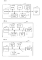
- FIG. 3 is a block diagram showing the principal parts of a numerical controller constituting the turning program creation apparatus.
- the numerical controller 10 comprises a processor 11 as well as a ROM 12, a RAM 13, a display unit 14, a nonvolatile memory 15, an operation panel 16, and so on that are connected to the processor 11 through a bus 17, as in conventional numerical controllers.
- Numerical controller 10 is connected to a machining tool 18 to be controlled. Machining program creation software is stored in nonvolatile memory 15. To create a machining program interactively using numerical controller 10, the operator loads the machining program creation software stored in nonvolatile memory 15 into RAM 13 and operates display unit 14 and operation panel 16 in the customary manner.
- FIG. 4 is a block diagram showing the principal parts of an interactive automatic programming apparatus constituting the turning program creation apparatus.
- the interactive automatic programming apparatus 20 comprises a processor 21 as well as a ROM 22, a RAM 23, a nonvolatile memory 24, a display unit 25, an operation panel 26, and so on, which are connected to processor 21 through a bus 27, as in conventional automatic interactive programming apparatuses.
- a processor 21 as well as a ROM 22, a RAM 23, a nonvolatile memory 24, a display unit 25, an operation panel 26, and so on, which are connected to processor 21 through a bus 27, as in conventional automatic interactive programming apparatuses.
- an operator loads machining program creation software stored in nonvolatile memory 24 into RAM 23 and operates display unit 25 and operation panel 26 in the customary manner.
- FIG. 5 is a block diagram showing principal parts of a personal computer constituting the turning program creation apparatus.
- the personal computer 30 comprises a processor 31 as well as a display unit 32, a RAM 33, a hard disk drive 34, a keyboard/mouse 35, and so on, which are connected to the processor 31 through a bus 36, as in conventional personal computers.
- An operator creates a machining program interactively using the display unit 32 and the keyboard/mouse 35 according to the machining program creation software stored in the hard disk drive 34 of personal computer 30 in the customary manner.
- FIG. 2 shows the cutting direction automatic determination process in the machining program creation process, executed by the processor in the device that constitutes the above turning program creation apparatus: processor 11 in numerical controller 10, processor 21 in interactive automatic programming apparatus 20, or processor 31 in personal computer 30.
- one element is taken from entered machined shape data (step S1) and whether the element is a straight line element or arc element is determined (step S2). If the element is a straight line element, the distance D (vertical difference) between its start point SP and end point EP in the X-axis direction is obtained and whether or not the distance D is equal to or greater than a preset value Ds is determined (step S3). This is equivalent to the determination process in (2) above, which is based on the distance D in the X-axis direction for a straight line element.
- step S4 the angle A that the straight line element makes with the axis of rotation (Z-axis) of the workpiece is obtained and whether or not the angle A is equal to or greater than a preset angle Aa is determined (step S4).
- the processing proceeds to step S6 and the cutting direction is set to the profile direction "a".
- step S5 When the angle A that the straight line element makes with the axis of rotation (Z-axis) of the workpiece is equal to or greater than the preset angle Aa, the cutting direction is set to the direction "b" from the rim toward the center of the workpiece, which is opposite to the profile direction "a" (step S5) , the processing proceeds to step S7 and the machining program is created.
- step S8 whether the last element of the machined shape has been reached or not is determined (step S8) and, if it has not been reached, the processing returns to step S1.
- step S2 If the element taken from the machined shape data is determined to be an arc element in step S2, the processing shifts from step S2 to step S9 and whether or not the radius R of the arc element is equal to or greater than a preset value Rs is determined. This is equivalent to the determination process in (4) above, in which the cutting direction is determined based on the radius R of the arc element.
- step S9 determination result "No"
- the cutting direction is set to the preset profile direction "a" (step S12)
- the processing proceeds to step S7, and the machining program is created with this cutting direction.
- the radius R obtained is equal to or greater than the preset value Rs (step S9, determination result "Yes")
- the angle A that the straight line (chord) between the start point SP and the end point EP of the arc makes with the axis of rotation (Z-axis) of the workpiece is obtained and whether or not the angle A (slant angle of the chord) is equal to or greater than the preset angle Ab is determined (step S10).
- This is equivalent to the determination process in (3) above, in which the cutting direction is determined based on the angle that the straight line between the start point and end point of the arc element makes with the Z-axis.
- the cutting direction is set to the profile direction "a" (step S12) and the machining program is created with the cutting direction "a” (step S7) .
- the cutting direction is set to the direction "b" from the rim toward the center of the workpiece (step S11), which is opposite to the profile direction, and the machining program is created with the cutting direction "b" (step S7).
- step S8 whether the last element of the machined shape has been reached or not is determined (step S8) and, if it has not been reached, the processing returns to step S1. The above procedure is then repeated to determine cutting directions for the entered machining shape, thereby automatically creating a machining program. If it is determined in step S8 that the last element of the machined shape has been reached, the process of creating the machining program is completed.
- the cutting direction is set to the direction "b" opposite to the profile direction "a" only when the distance D (vertical difference) of the straight line element in the X-axis direction is equal to or greater than the preset value Ds and the angle A (slang angle of the straight line element) that the straight line element makes with the axis of rotation (Z-axis) of the workpiece is equal to or greater than the preset angle Aa, that is, only when the condition D ⁇ Ds AND A ⁇ Aa is satisfied.
- the cutting direction is set to the direction "b" opposite to the profile direction "a" only when the radius R of the arc is greater than the preset value Rs and the angle A that the straight line between the start point and end point of the arc makes with the axis of rotation (Z-axis) of the workpiece is equal to or greater than the preset angle Ab, that is, only when the condition R ⁇ Rs AND A ⁇ Ab is satisfied.
- the cutting direction can be determined independently according to the results of determination processes (1) to (4) .
- the cutting direction may be set to direction "b" if either the condition D ⁇ Ds or the condition A ⁇ Aa is satisfied, and the cutting direction may be set to the profile direction "a" only when the condition D ⁇ Ds AND A ⁇ Aa is satisfied.
- the processing in FIG. 2 is changed so that, if step S3 produces a Yes result, the processing proceeds to step S5 or, if it produces a No result, the processing proceeds to step S4.
- the cutting direction may be set to direction "b" if either the condition R ⁇ Rs or the condition A ⁇ Ab is satisfied, and the cutting direction may be set to the profile direction "a" only if the condition R ⁇ Rs AND A ⁇ Ab is satisfied.
- step S9 produces a Yes result
- step S11 the processing proceeds to step S11 or, if it produces a No result
- step S10 the processing proceeds to step S10.
- the cutting direction may be determined according only to whether or not the distance D of the straight line in the X-axis direction is equal to or greater than the preset value Ds.
- the cutting direction may be determined on the basis only of whether or not the angle A that the straight line makes with the axis of rotation (Z-axis) of the workpiece is equal to or greater than the preset angle Aa.
- the cutting direction may be determined according only to whether or not the radius R of the arc is greater than the preset value Rs.
- the cutting direction may be determined according only to whether or not the angle A that the straight line (chord) between the start point and end point of the arc makes with the axis of rotation (Z-axis) of the workpiece is equal to or greater than the preset angle Ab.
- the cutting direction when the machining element is a straight line, if the distance D of the straight line in the X-axis direction is equal to or greater than the preset value Ds, the cutting direction may be set to the direction "b" opposite to the profile direction "a"; if the distance D is less than the preset value Ds, the cutting direction may be set to the profile direction "a".
- the cutting direction may be set to the direction "b" opposite to the profile direction "a”; if the angle A is less than the preset angle Aa, the cutting direction may be set to the profile direction "a".
- the cutting direction when the machining element is an arc, if the radius R of the arc is equal to or greater than the preset value Rs, the cutting direction may be set to the direction "b" opposite to the profile direction "a"; if the radius R is less than the preset value Rs, the cutting direction may be set to the profile direction "a".
- the cutting direction when the angle A that the straight line (chord) between the start point and end point of the arc makes with the axis of rotation (Z-axis) of the workpiece is equal to or greater than the preset angle Ab, the cutting direction may be set to the direction "b” opposite to the profile direction "a”; when the angle A is less than the preset angle Ab, the cutting direction may be set to the profile direction "a".
- the method of automatically determining the cutting direction may be selected depending on the target machining accuracy, workpiece material, or tool characteristics.
Landscapes
- Physics & Mathematics (AREA)
- Engineering & Computer Science (AREA)
- Geometry (AREA)
- Human Computer Interaction (AREA)
- Manufacturing & Machinery (AREA)
- General Physics & Mathematics (AREA)
- Automation & Control Theory (AREA)
- Numerical Control (AREA)
- Turning (AREA)
Applications Claiming Priority (1)
| Application Number | Priority Date | Filing Date | Title |
|---|---|---|---|
| JP2006274173A JP4256419B2 (ja) | 2006-10-05 | 2006-10-05 | 旋削加工用のプログラム作成装置 |
Publications (3)
| Publication Number | Publication Date |
|---|---|
| EP1909153A2 true EP1909153A2 (de) | 2008-04-09 |
| EP1909153A3 EP1909153A3 (de) | 2012-01-04 |
| EP1909153B1 EP1909153B1 (de) | 2013-06-12 |
Family
ID=38871795
Family Applications (1)
| Application Number | Title | Priority Date | Filing Date |
|---|---|---|---|
| EP07117052.6A Ceased EP1909153B1 (de) | 2006-10-05 | 2007-09-24 | Vorrichtung zur Erstellung eines Drehprogramms |
Country Status (4)
| Country | Link |
|---|---|
| US (1) | US7747336B2 (de) |
| EP (1) | EP1909153B1 (de) |
| JP (1) | JP4256419B2 (de) |
| CN (1) | CN101158862B (de) |
Families Citing this family (6)
| Publication number | Priority date | Publication date | Assignee | Title |
|---|---|---|---|---|
| JP2011016220A (ja) * | 2009-07-09 | 2011-01-27 | Mori Seiki Co Ltd | プログラミング装置 |
| JP4888619B1 (ja) * | 2011-06-14 | 2012-02-29 | 三菱電機株式会社 | 数値制御装置 |
| JP5752196B2 (ja) * | 2013-09-03 | 2015-07-22 | ファナック株式会社 | ワイヤ放電加工機用のプログラム作成装置 |
| JP6316057B2 (ja) * | 2014-03-28 | 2018-04-25 | オークマ株式会社 | 数値制御情報作成装置 |
| CN114137908B (zh) * | 2020-09-03 | 2025-04-25 | 上海电气电站设备有限公司 | 一种车削数控编程方法、装置及数控加工系统 |
| JP7722109B2 (ja) * | 2021-09-30 | 2025-08-13 | 新東工業株式会社 | ショットブラスト装置、検査方法、検査プログラム |
Family Cites Families (15)
| Publication number | Priority date | Publication date | Assignee | Title |
|---|---|---|---|---|
| US4928221A (en) * | 1988-04-11 | 1990-05-22 | Westinghouse Electric Corp. | Part program generating system |
| JPH07115277B2 (ja) | 1988-11-29 | 1995-12-13 | ファナック株式会社 | 輪郭形状加工方式 |
| JPH0698552B2 (ja) * | 1988-12-26 | 1994-12-07 | オ−クマ株式会社 | 数値制御情報作成装置における加工方法の決定方式 |
| JP2649838B2 (ja) * | 1989-03-15 | 1997-09-03 | オークマ 株式会社 | 数値制御情報作成装置における加工方法の決定方法 |
| JP2685325B2 (ja) * | 1990-03-30 | 1997-12-03 | オークマ株式会社 | 数値制御情報作成装置 |
| JP2752787B2 (ja) | 1990-11-29 | 1998-05-18 | オ−クマ株式会社 | 数値制御情報作成装置 |
| US5920170A (en) * | 1992-10-08 | 1999-07-06 | Yamanashi | Numerical control apparatus and numerical control method |
| US5406494A (en) * | 1994-03-17 | 1995-04-11 | Creative Technology Corporation | Numerical control system with operator controlled cutting |
| JP3731224B2 (ja) * | 1995-08-18 | 2006-01-05 | 三菱電機株式会社 | 研削砥石成形装置および方法 |
| US6096785A (en) | 1996-07-30 | 2000-08-01 | Novartis Nutrition Ag | Amino acid compositions and use thereof in treating renal dysfunction |
| JP2000084794A (ja) * | 1998-09-14 | 2000-03-28 | Makino Milling Mach Co Ltd | 加工処理装置 |
| JP4738585B2 (ja) * | 2000-10-26 | 2011-08-03 | シチズンホールディングス株式会社 | 加工プログラムのグラフ表示方法及びそのための装置 |
| EP1590712B1 (de) * | 2003-01-29 | 2011-03-02 | OPEN MIND Technologies AG | Verfahren zur steuerung von relativbewegungen eines werkzeuges gegen ein werkstück |
| JP2006048244A (ja) * | 2004-08-02 | 2006-02-16 | Fanuc Ltd | 加工プログラム作成装置 |
| JP4196936B2 (ja) * | 2004-11-16 | 2008-12-17 | 三菱電機株式会社 | 穴加工用ncプログラム作成装置及び穴加工ncプログラム作成装置用プログラム |
-
2006
- 2006-10-05 JP JP2006274173A patent/JP4256419B2/ja not_active Expired - Fee Related
-
2007
- 2007-09-12 CN CN200710154439XA patent/CN101158862B/zh not_active Expired - Fee Related
- 2007-09-19 US US11/902,201 patent/US7747336B2/en active Active
- 2007-09-24 EP EP07117052.6A patent/EP1909153B1/de not_active Ceased
Non-Patent Citations (1)
| Title |
|---|
| None |
Also Published As
| Publication number | Publication date |
|---|---|
| EP1909153B1 (de) | 2013-06-12 |
| EP1909153A3 (de) | 2012-01-04 |
| JP4256419B2 (ja) | 2009-04-22 |
| CN101158862A (zh) | 2008-04-09 |
| US20080086230A1 (en) | 2008-04-10 |
| CN101158862B (zh) | 2010-06-09 |
| JP2008087147A (ja) | 2008-04-17 |
| US7747336B2 (en) | 2010-06-29 |
Similar Documents
| Publication | Publication Date | Title |
|---|---|---|
| EP1980353B1 (de) | Steuerung für elektrische Drahterodiermaschinen | |
| EP1909153B1 (de) | Vorrichtung zur Erstellung eines Drehprogramms | |
| US20080109097A1 (en) | Machining step generating apparatus | |
| US20160224004A1 (en) | Machine tool with function to automatically modify cutting conditions | |
| WO1985002692A1 (fr) | Procede de determination d'etapes d'usinage pour programmation automatique | |
| EP2919084B1 (de) | Nc-programmerzeugungseinheit | |
| EP0229848A1 (de) | System zum selbsttätigen zeichnen eines werkzeugprofils | |
| US20060079987A1 (en) | Optimized machining controller for automatic machining device and automatic machining device with said controller | |
| US6859680B2 (en) | Numerical controlling unit having tool-breakage detecting function | |
| CN117120198B (zh) | 数值控制装置以及计算机可读取的存储介质 | |
| JP2007203346A (ja) | レーザ制御方法及びレーザ制御装置 | |
| CN106814689B (zh) | 数值控制装置 | |
| US5112169A (en) | Thread cutting method and apparatus | |
| JP3152053B2 (ja) | 切削条件設定方法および装置 | |
| JPH0688191B2 (ja) | 数値制御情報作成装置における加工部位の決定方法 | |
| US12474693B2 (en) | Speed adjustment device | |
| JP3082232B2 (ja) | 軸送り切削加工法 | |
| KR100206135B1 (ko) | 가공물 절삭 제어방법 | |
| JP3264054B2 (ja) | Nc文作成方法 | |
| JP6687575B2 (ja) | 数値制御装置 | |
| JP4363343B2 (ja) | 加工条件設定方法及び加工装置 | |
| WO2024189907A1 (ja) | 加工経路表示装置およびコンピュータ読み取り可能な記憶媒体 | |
| JP2685328B2 (ja) | 数値制御情報作成装置における形状定義方法 | |
| JPS61241043A (ja) | 加工デ−タの作成方式 | |
| JP2584366B2 (ja) | ワイヤ放電加工機のテーパ加工方法 |
Legal Events
| Date | Code | Title | Description |
|---|---|---|---|
| PUAI | Public reference made under article 153(3) epc to a published international application that has entered the european phase |
Free format text: ORIGINAL CODE: 0009012 |
|
| AK | Designated contracting states |
Kind code of ref document: A2 Designated state(s): AT BE BG CH CY CZ DE DK EE ES FI FR GB GR HU IE IS IT LI LT LU LV MC MT NL PL PT RO SE SI SK TR |
|
| AX | Request for extension of the european patent |
Extension state: AL BA HR MK RS |
|
| RAP1 | Party data changed (applicant data changed or rights of an application transferred) |
Owner name: FANUC CORPORATION |
|
| PUAL | Search report despatched |
Free format text: ORIGINAL CODE: 0009013 |
|
| AK | Designated contracting states |
Kind code of ref document: A3 Designated state(s): AT BE BG CH CY CZ DE DK EE ES FI FR GB GR HU IE IS IT LI LT LU LV MC MT NL PL PT RO SE SI SK TR |
|
| AX | Request for extension of the european patent |
Extension state: AL BA HR MK RS |
|
| RIC1 | Information provided on ipc code assigned before grant |
Ipc: G05B 19/4093 20060101AFI20111125BHEP |
|
| 17P | Request for examination filed |
Effective date: 20120702 |
|
| AKX | Designation fees paid |
Designated state(s): DE |
|
| GRAP | Despatch of communication of intention to grant a patent |
Free format text: ORIGINAL CODE: EPIDOSNIGR1 |
|
| GRAS | Grant fee paid |
Free format text: ORIGINAL CODE: EPIDOSNIGR3 |
|
| GRAA | (expected) grant |
Free format text: ORIGINAL CODE: 0009210 |
|
| AK | Designated contracting states |
Kind code of ref document: B1 Designated state(s): DE |
|
| REG | Reference to a national code |
Ref country code: DE Ref legal event code: R096 Ref document number: 602007030986 Country of ref document: DE Effective date: 20130808 |
|
| PLBE | No opposition filed within time limit |
Free format text: ORIGINAL CODE: 0009261 |
|
| STAA | Information on the status of an ep patent application or granted ep patent |
Free format text: STATUS: NO OPPOSITION FILED WITHIN TIME LIMIT |
|
| 26N | No opposition filed |
Effective date: 20140313 |
|
| REG | Reference to a national code |
Ref country code: DE Ref legal event code: R097 Ref document number: 602007030986 Country of ref document: DE Effective date: 20140313 |
|
| REG | Reference to a national code |
Ref country code: DE Ref legal event code: R082 Ref document number: 602007030986 Country of ref document: DE Representative=s name: HL KEMPNER PATENTANWAELTE, SOLICITORS (ENGLAND, DE Ref country code: DE Ref legal event code: R082 Ref document number: 602007030986 Country of ref document: DE Representative=s name: HL KEMPNER PATENTANWALT, RECHTSANWALT, SOLICIT, DE |
|
| PGFP | Annual fee paid to national office [announced via postgrant information from national office to epo] |
Ref country code: DE Payment date: 20230802 Year of fee payment: 17 |
|
| REG | Reference to a national code |
Ref country code: DE Ref legal event code: R119 Ref document number: 602007030986 Country of ref document: DE |
|
| PG25 | Lapsed in a contracting state [announced via postgrant information from national office to epo] |
Ref country code: DE Free format text: LAPSE BECAUSE OF NON-PAYMENT OF DUE FEES Effective date: 20250401 |