EP1909092A2 - Probenhaltergitter und Verfahren zur Beobachtung einer Gummi-Probe - Google Patents
Probenhaltergitter und Verfahren zur Beobachtung einer Gummi-Probe Download PDFInfo
- Publication number
- EP1909092A2 EP1909092A2 EP07019483A EP07019483A EP1909092A2 EP 1909092 A2 EP1909092 A2 EP 1909092A2 EP 07019483 A EP07019483 A EP 07019483A EP 07019483 A EP07019483 A EP 07019483A EP 1909092 A2 EP1909092 A2 EP 1909092A2
- Authority
- EP
- European Patent Office
- Prior art keywords
- mesh
- rubber slice
- fixed
- stretch
- portions
- Prior art date
- Legal status (The legal status is an assumption and is not a legal conclusion. Google has not performed a legal analysis and makes no representation as to the accuracy of the status listed.)
- Withdrawn
Links
Images




Classifications
-
- G—PHYSICS
- G01—MEASURING; TESTING
- G01N—INVESTIGATING OR ANALYSING MATERIALS BY DETERMINING THEIR CHEMICAL OR PHYSICAL PROPERTIES
- G01N3/00—Investigating strength properties of solid materials by application of mechanical stress
- G01N3/02—Details
- G01N3/04—Chucks
-
- G—PHYSICS
- G01—MEASURING; TESTING
- G01N—INVESTIGATING OR ANALYSING MATERIALS BY DETERMINING THEIR CHEMICAL OR PHYSICAL PROPERTIES
- G01N3/00—Investigating strength properties of solid materials by application of mechanical stress
- G01N3/08—Investigating strength properties of solid materials by application of mechanical stress by applying steady tensile or compressive forces
-
- H—ELECTRICITY
- H01—ELECTRIC ELEMENTS
- H01J—ELECTRIC DISCHARGE TUBES OR DISCHARGE LAMPS
- H01J37/00—Discharge tubes with provision for introducing objects or material to be exposed to the discharge, e.g. for the purpose of examination or processing thereof
- H01J37/02—Details
- H01J37/20—Means for supporting or positioning the object or the material; Means for adjusting diaphragms or lenses associated with the support
-
- H—ELECTRICITY
- H01—ELECTRIC ELEMENTS
- H01J—ELECTRIC DISCHARGE TUBES OR DISCHARGE LAMPS
- H01J37/00—Discharge tubes with provision for introducing objects or material to be exposed to the discharge, e.g. for the purpose of examination or processing thereof
- H01J37/26—Electron or ion microscopes; Electron or ion diffraction tubes
-
- H—ELECTRICITY
- H01—ELECTRIC ELEMENTS
- H01J—ELECTRIC DISCHARGE TUBES OR DISCHARGE LAMPS
- H01J2237/00—Discharge tubes exposing object to beam, e.g. for analysis treatment, etching, imaging
- H01J2237/20—Positioning, supporting, modifying or maintaining the physical state of objects being observed or treated
- H01J2237/2007—Holding mechanisms
-
- H—ELECTRICITY
- H01—ELECTRIC ELEMENTS
- H01J—ELECTRIC DISCHARGE TUBES OR DISCHARGE LAMPS
- H01J2237/00—Discharge tubes exposing object to beam, e.g. for analysis treatment, etching, imaging
- H01J2237/20—Positioning, supporting, modifying or maintaining the physical state of objects being observed or treated
- H01J2237/206—Modifying objects while observing
- H01J2237/2062—Mechanical constraints
-
- H—ELECTRICITY
- H01—ELECTRIC ELEMENTS
- H01J—ELECTRIC DISCHARGE TUBES OR DISCHARGE LAMPS
- H01J2237/00—Discharge tubes exposing object to beam, e.g. for analysis treatment, etching, imaging
- H01J2237/26—Electron or ion microscopes
- H01J2237/28—Scanning microscopes
Definitions
- the present invention relates to a mesh for holding a sample when the sample is observed by a microscope and a method of observing a rubber slice used as the sample by holding the rubber slice by the mesh, and more particularly to a mesh capable of observing a rubber slice in a stretch process and the rubber slice both in the stretch process and a contraction process.
- TEM transmissive electron microscope
- a disk-shaped mesh 1 having a diameter of about 3mm has reticulate openings 2, narrow groove-shaped openings 3, and a single hole 4 as shown in Fig. 10 so that the mesh 1 is capable of transmitting electron beams therethrough.
- a thinned sample 4 is fixed to an upper surface of a central portion of the mesh 1 having openings 3 formed therethrough.
- a contraction process is useful for analyzing breakage, damage, deterioration, and wear of rubber and the mechanism of the generation of hysteresis loss and is also useful for making a combined design based on these analyses.
- Patent document Japanese Patent Application Laid-Open No.11-329325
- the present invention has been made in view of the above-described problems. It is an object of the present invention to provide a mesh allowing a rubber slice to be observed in a stretch process and in addition both in the stretch process and a contraction process and a method of observing the rubber slice by using the mesh.
- the first invention provides a mesh supporting a rubber slice in a stretch process so that the rubber slice can be observed by a microscope, wherein an upper surface of a central portion of the mesh is set as a placing region to which the rubber slice is fixed; left and right sides of the mesh sandwiching the placing region therebetween are set as left and right to-be-fixed portions to be fixed to sample holder separation portions respectively to be moved in a stretch direction; and a slit for opening use is formed by cutting the mesh in a required length from an outer edge thereof disposed between the left and right to-be-fixed portions in a direction orthogonal to the stretch direction or a direction inclined thereto.
- the slit for opening use is opened toward the outer edge of the mesh to stretch the mesh in the stretch direction so that the rubber slice, left and right sides of which have been fixed to the to-be-fixed portions respectively is stretched.
- the slit for opening use is formed by cutting the mesh in the required length from a portion of its periphery disposed between its left and right to-be-fixed portions in the direction orthogonal to the stretch direction or the direction inclined thereto. Therefore by separating the sample holder separation portions to which the left and right sides of the mesh have been fixed respectively from each other and moving the sample holder separation portions in the stretch direction, the mesh is uniformly stretched in the stretch direction while the slits for opening use is being opened, and the rubber slice fixed to the mesh is also stretched, as the mesh is stretched.
- each slit for opening use is not restricted specifically respectively, provided that the rubber slice on the mesh can be stretched by extending the mesh in the stretch direction, but appropriately set according to the configuration of the opening of the mesh, the configuration of the rubber slice fixed onto the mesh, and the fixing position of the rubber slice.
- the left side of the slit for opening use and the right side thereof are disposed symmetrically with respect to the center of the mesh.
- the second invention provides a mesh supporting a rubber slice in a stretch process and a contraction process so that the rubber slice can be observed by a microscope.
- An upper surface of a central portion of the mesh is set as a placing region, having an opening, to which the rubber slice is fixed; left and right sides of the mesh sandwiching the placing region therebetween are set as left and right to-be-fixed portions to be fixed to sample holder separation portions to be moved in a stretch direction; and a slit for dividing use is formed by cutting the mesh from an outer edge thereof disposed between the left and right to-be-fixed portions toward the rubber slice-placing region in a direction orthogonal to the stretch direction or a direction inclined thereto.
- the mesh has the slit for dividing use formed from a portion of its periphery disposed between the left and right to-be-fixed portions of the mesh to be fixed to the sample holder separation portions respectively toward the rubber slice-placing position of the mesh in the direction orthogonal to the stretch direction of the rubber slice or the direction inclined thereto. Therefore by moving the sample holder separation portions which are provided on the sample holder and to which the left and right sides of the mesh have been fixed respectively in the stretch direction, the mesh is divided into the left and right parts in the stretch direction and moved away from each other.
- the rubber slice fixed to the left and right parts of the mesh is stretched uniformly in the stretch direction owing to the division of the mesh and move-away of the left and right parts thereof.
- the slit for dividing use is formed in the direction orthogonal to the stretch direction or the direction inclined thereto, it is possible to stretch the rubber slice in the stretch direction by dividing the mesh.
- to form the slit for dividing use in the direction orthogonal to the stretch direction is simplest and allows the rubber slice to be uniformly stretched in the stretch direction.
- the slit for dividing use is formed by inclining it to the stretch direction, it is especially preferable to incline the slit for dividing use not less than 10 degrees to the stretch direction.
- a reticulate opening or a narrow groove-shaped opening is formed in the rubber slice-placing region.
- the slit for opening use or the slit for dividing use is formed in a peripheral portion of the mesh surrounding the reticulate opening or the narrow groove-shaped opening by cutting the mesh from the outer edge thereof.
- the mesh may have the reticulate opening or the narrow-groove-shaped opening formed at the rubber slice-placing position.
- the slit for opening use or the slit for dividing use is formed not only in the peripheral portion of the mesh constructing the peripheral frame thereof but also in the peripheral portion of thread surrounding the reticulate opening, it is often difficult to extend the mesh in the stretch direction or divide the mesh into the left and right parts by opening the slit for opening use.
- the slit for dividing use is formed by traversing the placing region through the opening. For example, by only forming one slit for dividing use at the upper and peripheral portions of the mesh surrounding the narrow-groove-shaped opening, the mesh can be divided into left and right parts.
- the reticulate opening and the narrow-groove-shaped opening do not necessarily have to be formed in the placing region.
- the mesh of each of the first and second inventions can be used especially preferably for a transmissive electron microscope (TEM) and a scan type electron microscope (SEM) and in addition for a scan type probe microscope (SPM), a laser microscope, and an optical microscope.
- TEM transmissive electron microscope
- SEM scan type electron microscope
- SPM scan type probe microscope
- the third invention provides a method of observing a rubber slice, wherein the rubber slice fixed to the rubber slice-placing region of the mesh is stretched by moving the sample holder separation portions to which left and right sides of the mesh of the first invention have been fixed respectively in a stretch direction so that the rubber slice in a stretch process is observed by a microscope.
- the third invention by using the mesh of the first invention through which the slit for opening use is formed by cutting the mesh, the rubber slice is stretched by opening the slit for opening use and extending the mesh in the stretch direction. Therefore as the mesh is extended, the mesh remains deformed to some extent.
- the third invention is not suitable for observing the rubber slice in the contraction process but suitable for observing the rubber slice in the stretch direction.
- the fourth invention provides a method of observing a rubber slice, wherein by moving sample holder separation portions to which left and right sides of the mesh of the second invention have been fixed respectively in a stretch direction, the rubber slice fixed to a rubber slice-placing region of the mesh is stretched to observe the rubber slice in a stretch process by a microscope, and thereafter by moving the sample holder separation portions in a contraction direction, the rubber slice fixed to the rubber slice-placing region of the mesh is contracted so that the rubber slice in a contraction process is observed by a microscope.
- the rubber slice is stretched.
- the mesh does not remain deformed. Therefore it is possible to observe the rubber slice not only in the stretch process but also in the contraction process (return process), which is useful for analyzing the breakage, damage, deterioration, and wear of rubber, the mechanism of reinforcing a polymer, a filler, and the like, and the analysis of the mechanism of the generation of hysteresis loss, and for making a combined design based on these analyses.
- the slit for opening use of the mesh and the slit for dividing use thereof used in the method of the third and fourth inventions of observing the rubber slice by cutting the mesh with razor, surgical knife, cutter or the like after the rubber slice is fixed to the upper surface of the central portion of the mesh.
- the slit for opening use is formed by cutting the mesh in the required length from the outer edge thereof disposed between its left and right to-be-fixed portions in the direction orthogonal to the stretch direction or the direction inclined thereto. Therefore by moving the sample holder separation portions to which the left and right sides of the mesh have been fixed respectively in the stretch direction, the mesh is uniformly stretched in the stretch direction while the slits for opening use is being opened, and the rubber slice fixed to the mesh is also stretched, as the mesh is stretched. Accordingly by moving the sample holder separation portions to which the left and right sides of the mesh have been fixed respectively in the stretch direction, it is possible to stretch the rubber slice at any desired degree of stretching and directly observe the state of the rubber slice, as the third invention provides.
- the mesh has the slit for dividing use formed from a portion of its periphery disposed between the left and right to-be-fixed portions of the mesh to be fixed to the sample holder separation portions respectively toward the rubber slice-placing position of the mesh in the direction orthogonal to the stretch direction of the rubber slice or the direction inclined thereto. Therefore by moving the sample holder separation portions to which the left and right sides of the mesh have been fixed respectively in the stretch direction, the mesh is divided into the left and right parts in the stretch direction.
- the rubber slice fixed to the left and right parts of the mesh is stretched uniformly in the stretch direction owing to the division of the mesh and the move-away of the left and right parts thereof.
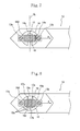
- Figs. 1 through 5 show the first embodiment of the present invention.
- a mesh 11 of the first embodiment has narrow groove-shaped openings 11a in a placing region 11b where a rubber slice 10 is placed and slits 12a, 12b for dividing use communicating with the narrow groove-shaped openings 11a.
- the rubber slice 10 to be used as a sample shown in Fig. 2 is fixed to the mesh-placing region 11b disposed on an upper surface of the center of the mesh 11 which has three narrow groove-shaped openings 11a at the center thereof, as shown in Figs. 3 and 4, the slits 12a, 12b for dividing use are sequentially formed on the mesh 11 by using a cutting blade (razor in the first embodiment).
- the thinned rubber slice 10 (1mm (length) ⁇ 2mm (width) ⁇ 200nm (thickness) is made from a rubber composition having components mixed at ratios shown in table 1 by using a microtome (not shown, commercial name: Ultramicrotome EM VC6, produced by LEICA Inc.).
- the rubber slice 10 is placed on and fixed to the mesh-placing region 11b which is disposed on the upper surface of the center of the mesh 11 (diameter: 3mm) which has the three narrow groove-shaped openings 11a (11a-1, 11a-2, and 11a-3) shown in Fig. 1 by using an exclusive loop (not shown) with the rubber slice 10 straddling over the three narrow groove-shaped openings 11a (Fig. 2).
- Table 1 Compounding components Mixing amount (part by weight) Styrene butadiene rubber 100 Carbon black (N220) 70 Sulfur 1.5 Zinc oxide 3 Accelerator B 1
- the mesh 11 is placed on a sample holder 13. Both left and right sides (to-be-fixed portion 11d, 11e) of the mesh 11 are fixed to hold-down plates 13a-1, 13b-1 of sample holder separation portions 13a, 13b by screws 13a-2, 13b-2.
- the slits 12a, 12b for dividing use are formed by cutting upper and lower centers of a peripheral frame 11c surrounding the narrow groove-shaped opening 11a of the mesh 11 in a direction orthogonal to a stretch direction (left-to-right direction) of the rubber slice 10 by using a cutting blade (not shown). In this manner, the mesh of the first embodiment is obtained.
- the slits 12a, 12b for dividing use are formed by cutting the peripheral frame 11c continually with the central opening 11a-2 of the three narrow groove-shaped openings 11a.
- the slits 12a, 12b for dividing use are formed at the upper and lower peripheral portions of the central opening 11a-2 of the mesh 11.
- the slit 12a for dividing use, the opening 11a-2, and the slit 12b for dividing use are traversed through a placing portion where the rubber slice 10 is placed to form a division line SL.
- the mesh 11 is divided into left and right parts 11A, 11B.
- the slits 12a, 12b for dividing use are located at the upper and lower positions in the drawings. Because the mesh 11 is horizontally disposed, the slits 12a, 12b for dividing use are located at front and rear sides of the horizontally disposed opening 11a-2.
- the left and right parts 11A, 11B of the mesh 11 formed by dividing the mesh 11 at the division line SL formed as the boundary are fixed to the sample holder separation portions 13a, 13b respectively.
- the width of the division line SL gradually increases.
- the rubber slice 10 whose left and right sides have been fixed to the left and right parts 11A, 11B of the mesh 11 are stretched in the left-to-right direction in the drawing.
- the sample holder 13 to which the mesh 11 has been fixed is set on a transmissive electron microscope (not shown) (H7100 produced by Hitachi Co., Ltd., acceleration voltage 100 KV) to observe the rubber slice 10 having a degree of stretching at 0%.
- the rubber slice 10 is stretched by moving the sample holder separation portion 13b of both sample holder separation portions 13a, 13b to which the left and right sides 11d, 11e of the mesh 11 have been fixed respectively in the stretch direction (direction shown by an arrow A) to observe the rubber slice 10 having the degree of stretching at 50%, 100%, and 150% in a stretch process.
- the left and right parts 11A, 11B of the mesh 11 are approached to each other by moving the sample holder separation portion 13b in a direction shown with an arrow B to contract the rubber slice 10 so that the rubber slice 10 having the degree of stretching at 100%, 50%, and 0% in a contraction process (return process) is observed.
- the mesh 11 of the present invention has the slits 12a, 12b for dividing use formed from a portion of its periphery disposed between the left and right to-be-fixed portions 11d, 11e of the mesh 11 to be fixed to the sample holder separation portions 13a, 13b respectively toward the rubber slice-placing position 11b of the mesh 11 in the direction orthogonal to the stretch direction (left-to-right direction) of the rubber slice 10. Therefore by moving the sample holder separation portion 13b of the sample holder separation portions 13a, 13b to which the left and right sides 11d, 11e of the mesh 11 have been fixed respectively in the stretch direction (the direction shown by the arrow A), the mesh 11 is divided into the left and right parts 2A, 2B.
- the rubber slice 10 fixed to the left and right parts 2A, 2B of the mesh 11 is stretched uniformly in the stretch direction owing to the division and move-away of the mesh 11.
- the sample holder separation portion 13b of the sample holder separation portions 13a, 13b to which the left and right sides 11d, 11e of the mesh 11 have been fixed respectively in the stretch direction it is possible to stretch the rubber slice 10 at a desired degree of stretching without deforming the mesh 11 and directly observe the rubber slice 10 in the stretch process.
- Figs. 6(A) through 6(C) show modifications of the first embodiment.
- an opening is generated between divided parts of the mesh.
- the opening does not necessarily have to be formed.
- the peripheral frame 11c holds reticulate lines 100 consisting of fibers to form narrow groove-shaped openings 100a.
- slits 12-3 for dividing use are formed through the peripheral frame 11c and the reticulate lines 100.
- Fig. 7 shows a second embodiment.
- a mesh 14 of the second embodiment has one narrow groove-shaped opening 14a formed by cutting a lower side of a peripheral frame 14c.
- One slit 15 for dividing use is formed at an upper side of the peripheral frame 14c to form the division line SL of the narrow groove-shaped opening 14a and the slit 15 for dividing use.
- the slit 15 for dividing use is formed in the direction orthogonal to the stretch direction (left-to-right direction).
- the mesh 14 is divided into left and right parts, and without deforming the mesh 14, the rubber slice 10 can be stretched uniformly in the stretch direction. Therefore similarly to the first embodiment, the rubber slice 10 in the stretch process and the contraction process (return process) can be observed.
- Fig. 8 shows a third embodiment.
- slits 17a, 17b, and 17c for opening use are alternately formed at upper and lower positions of a peripheral frame 16c surrounding a narrow groove-shaped opening 16a in the direction orthogonal to the stretch direction (left-to-right direction) of the rubber slice 10 to such an extent that the slits 17a, 17b, and 17c for opening use do not communicate with the narrow groove-shaped opening 16a.
- the slits 17a, 17b, and 17c for opening use are formed after the left and right sides 16d, 16e of the mesh 16 are fixed to the sample holder separation portions 13a, 13b respectively with the rubber slice 10 fixed to the mesh 16.
- Other constructions of the third embodiment are similar to those of the first embodiment.
- the mesh 11 has the slits 17a, 17b, and 17c for opening use formed vertically and alternately on the peripheral frame 16c disposed between the left and right to-be-fixed portions 16d, 16e of the mesh 16 to be fixed to the sample holder separation portions 13a, 13b respectively in the direction orthogonal to the stretch direction (left-to-right direction).
- the mesh 16 is stretched in the stretch direction, while the slits 17a, 17b, and 17c for opening use are being opened, and the rubber slice 10 fixed to the mesh 16 is also stretched, as the mesh 16 is stretched.
- the mesh 16 having the slit for opening use can be used in the contraction process.
- Figs. 9(A) and 9(B) show modifications of the third embodiment.
- a large number of narrow groove-shaped openings 16a is formed side by side in the central portion of the mesh 16 in the left-to-right direction, and slits for opening use 17 are formed alternately at upper and lower portions of the narrow groove-shaped openings 16a.
- a slit for opening use 17e is formed by cutting the mesh 16 from an upper peripheral edge of the mesh 16
- a slit for opening use 17f is formed by cutting the mesh 16 from a lower peripheral edge of the mesh 16 with a sphere formed at a leading end of each of the slits 17e, 17f.
- the slit is formed after the rubber slice is fixed to the mesh. But if the position where the slit for opening use is formed does not interfere with the region of the mesh 16 where the rubber slice 10 is placed, the slit may be formed through the mesh 16 before the rubber slice 10 is placed on and fixed to the mesh 16.
- the mesh of the present invention is preferably used to hold the rubber slice in observing the state of the rubber slice in the stretch process and the contraction process.
- the mesh of the present invention can be also used to observe a sample to be stretched, for example, a film made of resin in the stretch direction and the contraction process.
- the mesh of the present invention is preferably used as a sample-holding material in observing a sample by a scan type electron microscope, a transmissive electron microscope, a scan type probe microscope, a laser microscope, and an optical microscope.
Landscapes
- Chemical & Material Sciences (AREA)
- Analytical Chemistry (AREA)
- Physics & Mathematics (AREA)
- Health & Medical Sciences (AREA)
- Life Sciences & Earth Sciences (AREA)
- Biochemistry (AREA)
- General Health & Medical Sciences (AREA)
- General Physics & Mathematics (AREA)
- Immunology (AREA)
- Pathology (AREA)
- Sampling And Sample Adjustment (AREA)
Applications Claiming Priority (1)
| Application Number | Priority Date | Filing Date | Title |
|---|---|---|---|
| JP2006275543A JP4772638B2 (ja) | 2006-10-06 | 2006-10-06 | メッシュおよびゴム切片の観察方法 |
Publications (2)
| Publication Number | Publication Date |
|---|---|
| EP1909092A2 true EP1909092A2 (de) | 2008-04-09 |
| EP1909092A3 EP1909092A3 (de) | 2014-01-01 |
Family
ID=38980899
Family Applications (1)
| Application Number | Title | Priority Date | Filing Date |
|---|---|---|---|
| EP07019483.2A Withdrawn EP1909092A3 (de) | 2006-10-06 | 2007-10-04 | Probenhaltergitter und Verfahren zur Beobachtung einer Gummi-Probe |
Country Status (3)
| Country | Link |
|---|---|
| US (1) | US7675043B2 (de) |
| EP (1) | EP1909092A3 (de) |
| JP (1) | JP4772638B2 (de) |
Cited By (2)
| Publication number | Priority date | Publication date | Assignee | Title |
|---|---|---|---|---|
| CN109037014A (zh) * | 2018-08-20 | 2018-12-18 | 镇江乐华电子科技有限公司 | 微拉伸机构及其使用方法 |
| CN113608344A (zh) * | 2021-08-19 | 2021-11-05 | 河南科技大学第一附属医院 | 一种用于病理切片的数据观察装置 |
Families Citing this family (5)
| Publication number | Priority date | Publication date | Assignee | Title |
|---|---|---|---|---|
| CN101866804B (zh) * | 2010-04-14 | 2012-05-16 | 北京富纳特创新科技有限公司 | 透射电镜微栅 |
| CN101866803B (zh) * | 2010-04-14 | 2013-03-13 | 北京富纳特创新科技有限公司 | 透射电镜微栅 |
| JP5532425B2 (ja) * | 2010-08-27 | 2014-06-25 | 株式会社日立ハイテクノロジーズ | 荷電粒子装置用試料ホルダ |
| CN105372805B (zh) * | 2015-12-16 | 2017-10-13 | 华北电力科学研究院有限责任公司 | 能够用于观察复型薄膜的显微镜载物片和观察方法 |
| JP6433550B1 (ja) * | 2017-07-19 | 2018-12-05 | 株式会社日立製作所 | 試料保持機構、及び荷電粒子線装置 |
Family Cites Families (6)
| Publication number | Priority date | Publication date | Assignee | Title |
|---|---|---|---|---|
| FR2704649B1 (fr) * | 1993-04-30 | 1995-07-21 | Centre Nat Rech Scient | Machine de traction in situ et eprouvette pour microscope electronique a balayage. |
| JPH11230895A (ja) * | 1998-02-10 | 1999-08-27 | Ricoh Co Ltd | 樹脂成形体の密着力測定装置 |
| JPH11329325A (ja) | 1998-05-12 | 1999-11-30 | Canon Inc | メッシュおよび薄片試料の作製方法 |
| DE10029253C1 (de) * | 2000-06-14 | 2001-10-25 | Siemens Ag | Direktgeheizter thermionischer Flachemitter |
| NL1023717C2 (nl) * | 2003-06-20 | 2004-12-21 | Fei Co | Preparaatdrager voor het dragen van een met een elektronenbundel te doorstralen preparaat. |
| DE10362116B4 (de) * | 2003-09-17 | 2008-08-28 | Carl Zeiss Nts Gmbh | Verfahren zur Präparation einer Probe für elektronenmikroskopische Untersuchungen, sowie dabei verwendeter Greifer |
-
2006
- 2006-10-06 JP JP2006275543A patent/JP4772638B2/ja not_active Expired - Fee Related
-
2007
- 2007-10-04 US US11/905,803 patent/US7675043B2/en not_active Expired - Fee Related
- 2007-10-04 EP EP07019483.2A patent/EP1909092A3/de not_active Withdrawn
Cited By (2)
| Publication number | Priority date | Publication date | Assignee | Title |
|---|---|---|---|---|
| CN109037014A (zh) * | 2018-08-20 | 2018-12-18 | 镇江乐华电子科技有限公司 | 微拉伸机构及其使用方法 |
| CN113608344A (zh) * | 2021-08-19 | 2021-11-05 | 河南科技大学第一附属医院 | 一种用于病理切片的数据观察装置 |
Also Published As
| Publication number | Publication date |
|---|---|
| EP1909092A3 (de) | 2014-01-01 |
| JP4772638B2 (ja) | 2011-09-14 |
| US20080083884A1 (en) | 2008-04-10 |
| US7675043B2 (en) | 2010-03-09 |
| JP2008096161A (ja) | 2008-04-24 |
Similar Documents
| Publication | Publication Date | Title |
|---|---|---|
| EP1909092A2 (de) | Probenhaltergitter und Verfahren zur Beobachtung einer Gummi-Probe | |
| Schaffer et al. | Sample preparation for atomic-resolution STEM at low voltages by FIB | |
| Shan et al. | Mechanical annealing and source-limited deformation in submicrometre-diameter Ni crystals | |
| DE102010032894B4 (de) | Tem-Lamelle, Verfahren zu ihrer Herstellung und Vorrichtung zum Ausführen des Verfahrens | |
| DE102012217761B4 (de) | Verfahren zur Vermeidung von Artefakten beim Serial Block Face Imaging | |
| Miyamoto et al. | Dislocation structures and crystal orientations of copper single crystals deformed by equal-channel angular pressing | |
| US12198895B2 (en) | Method and device for preparing a microscopic sample from a volume sample | |
| JP6876455B2 (ja) | 観察方法および試料作製方法 | |
| Stockdale et al. | A rapid FIB-notch technique for characterizing the internal morphology of high-performance fibers | |
| CN102954975A (zh) | 用于分析具有填料颗粒的橡胶混合物的方法 | |
| US7705329B2 (en) | Charged particle beam processing apparatus | |
| Sakurai et al. | High‐performance, focusing‐type, time‐of‐flight atom probe with a channeltron as a signal detector | |
| JP2000271895A (ja) | ミクロトームによる試料作成方法及びミクロトーム | |
| CN102486441B (zh) | Tem样品的再加工方法 | |
| US20220268715A1 (en) | Crystal defect observation method for compound semiconductor | |
| US7335882B1 (en) | High resolution low dose transmission electron microscopy real-time imaging and manipulation of nano-scale objects in the electron beam | |
| JP6712364B1 (ja) | 糸状物の切断装置及び切断方法 | |
| CN214279902U (zh) | 一种扫描电镜用带有定位夹紧功能的样品台座 | |
| JP2019117697A (ja) | 透過電子顕微鏡用グリッド、圧縮試験用治具および分析ユニット | |
| Kessel et al. | Residual strain in free-standing CdTe nanowires overgrown with HgTe | |
| DE102023109043B3 (de) | Vorrichtung, Computerprogrammprodukt und Verfahren zur Präparation von mikroskopischen Proben mittels Backside-Thinning | |
| Schweizer | Manipulation of individual defects in 2D and layered materials | |
| CN217132719U (zh) | 一种实现不同应力状态的金属板材拉剪试样 | |
| JP2020026968A (ja) | 分析用試料作製方法および分析方法 | |
| Vogl | Functional Nanowires studied with correlative in situ Light and Electron Microscopy |
Legal Events
| Date | Code | Title | Description |
|---|---|---|---|
| PUAI | Public reference made under article 153(3) epc to a published international application that has entered the european phase |
Free format text: ORIGINAL CODE: 0009012 |
|
| AK | Designated contracting states |
Kind code of ref document: A2 Designated state(s): AT BE BG CH CY CZ DE DK EE ES FI FR GB GR HU IE IS IT LI LT LU LV MC MT NL PL PT RO SE SI SK TR |
|
| AX | Request for extension of the european patent |
Extension state: AL BA HR MK RS |
|
| PUAL | Search report despatched |
Free format text: ORIGINAL CODE: 0009013 |
|
| RIC1 | Information provided on ipc code assigned before grant |
Ipc: H01J 37/20 20060101ALI20131121BHEP Ipc: G01N 33/44 20060101ALI20131121BHEP Ipc: G01N 3/04 20060101AFI20131121BHEP Ipc: G02B 21/34 20060101ALI20131121BHEP Ipc: G01N 3/08 20060101ALI20131121BHEP |
|
| AK | Designated contracting states |
Kind code of ref document: A3 Designated state(s): AT BE BG CH CY CZ DE DK EE ES FI FR GB GR HU IE IS IT LI LT LU LV MC MT NL PL PT RO SE SI SK TR |
|
| AX | Request for extension of the european patent |
Extension state: AL BA HR MK RS |
|
| 17P | Request for examination filed |
Effective date: 20140626 |
|
| RBV | Designated contracting states (corrected) |
Designated state(s): AT BE BG CH CY CZ DE DK EE ES FI FR GB GR HU IE IS IT LI LT LU LV MC MT NL PL PT RO SE SI SK TR |
|
| AKX | Designation fees paid |
Designated state(s): DE FR GB |
|
| 17Q | First examination report despatched |
Effective date: 20151118 |
|
| STAA | Information on the status of an ep patent application or granted ep patent |
Free format text: STATUS: THE APPLICATION IS DEEMED TO BE WITHDRAWN |
|
| 18D | Application deemed to be withdrawn |
Effective date: 20160503 |