EP1908915A2 - Procédé de montage pour porte coulissante - Google Patents
Procédé de montage pour porte coulissante Download PDFInfo
- Publication number
- EP1908915A2 EP1908915A2 EP07116018A EP07116018A EP1908915A2 EP 1908915 A2 EP1908915 A2 EP 1908915A2 EP 07116018 A EP07116018 A EP 07116018A EP 07116018 A EP07116018 A EP 07116018A EP 1908915 A2 EP1908915 A2 EP 1908915A2
- Authority
- EP
- European Patent Office
- Prior art keywords
- winding shaft
- roller
- curtain
- montagezugmittel
- wound
- Prior art date
- Legal status (The legal status is an assumption and is not a legal conclusion. Google has not performed a legal analysis and makes no representation as to the accuracy of the status listed.)
- Granted
Links
Images


Classifications
-
- E—FIXED CONSTRUCTIONS
- E06—DOORS, WINDOWS, SHUTTERS, OR ROLLER BLINDS IN GENERAL; LADDERS
- E06B—FIXED OR MOVABLE CLOSURES FOR OPENINGS IN BUILDINGS, VEHICLES, FENCES OR LIKE ENCLOSURES IN GENERAL, e.g. DOORS, WINDOWS, BLINDS, GATES
- E06B9/00—Screening or protective devices for wall or similar openings, with or without operating or securing mechanisms; Closures of similar construction
- E06B9/02—Shutters, movable grilles, or other safety closing devices, e.g. against burglary
- E06B9/08—Roll-type closures
- E06B9/11—Roller shutters
- E06B9/17—Parts or details of roller shutters, e.g. suspension devices, shutter boxes, wicket doors, ventilation openings
-
- E—FIXED CONSTRUCTIONS
- E06—DOORS, WINDOWS, SHUTTERS, OR ROLLER BLINDS IN GENERAL; LADDERS
- E06B—FIXED OR MOVABLE CLOSURES FOR OPENINGS IN BUILDINGS, VEHICLES, FENCES OR LIKE ENCLOSURES IN GENERAL, e.g. DOORS, WINDOWS, BLINDS, GATES
- E06B9/00—Screening or protective devices for wall or similar openings, with or without operating or securing mechanisms; Closures of similar construction
- E06B9/56—Operating, guiding or securing devices or arrangements for roll-type closures; Spring drums; Tape drums; Counterweighting arrangements therefor
- E06B9/80—Safety measures against dropping or unauthorised opening; Braking or immobilising devices; Devices for limiting unrolling
- E06B2009/801—Locking arrangements
- E06B2009/802—Locking arrangements located in or close to shutter box
-
- E—FIXED CONSTRUCTIONS
- E06—DOORS, WINDOWS, SHUTTERS, OR ROLLER BLINDS IN GENERAL; LADDERS
- E06B—FIXED OR MOVABLE CLOSURES FOR OPENINGS IN BUILDINGS, VEHICLES, FENCES OR LIKE ENCLOSURES IN GENERAL, e.g. DOORS, WINDOWS, BLINDS, GATES
- E06B9/00—Screening or protective devices for wall or similar openings, with or without operating or securing mechanisms; Closures of similar construction
- E06B9/02—Shutters, movable grilles, or other safety closing devices, e.g. against burglary
- E06B9/08—Roll-type closures
- E06B9/11—Roller shutters
- E06B9/17—Parts or details of roller shutters, e.g. suspension devices, shutter boxes, wicket doors, ventilation openings
- E06B9/171—Rollers therefor; Fastening roller shutters to rollers
-
- E—FIXED CONSTRUCTIONS
- E06—DOORS, WINDOWS, SHUTTERS, OR ROLLER BLINDS IN GENERAL; LADDERS
- E06B—FIXED OR MOVABLE CLOSURES FOR OPENINGS IN BUILDINGS, VEHICLES, FENCES OR LIKE ENCLOSURES IN GENERAL, e.g. DOORS, WINDOWS, BLINDS, GATES
- E06B9/00—Screening or protective devices for wall or similar openings, with or without operating or securing mechanisms; Closures of similar construction
- E06B9/56—Operating, guiding or securing devices or arrangements for roll-type closures; Spring drums; Tape drums; Counterweighting arrangements therefor
- E06B9/58—Guiding devices
-
- E—FIXED CONSTRUCTIONS
- E06—DOORS, WINDOWS, SHUTTERS, OR ROLLER BLINDS IN GENERAL; LADDERS
- E06B—FIXED OR MOVABLE CLOSURES FOR OPENINGS IN BUILDINGS, VEHICLES, FENCES OR LIKE ENCLOSURES IN GENERAL, e.g. DOORS, WINDOWS, BLINDS, GATES
- E06B9/00—Screening or protective devices for wall or similar openings, with or without operating or securing mechanisms; Closures of similar construction
- E06B9/56—Operating, guiding or securing devices or arrangements for roll-type closures; Spring drums; Tape drums; Counterweighting arrangements therefor
- E06B9/80—Safety measures against dropping or unauthorised opening; Braking or immobilising devices; Devices for limiting unrolling
- E06B9/82—Safety measures against dropping or unauthorised opening; Braking or immobilising devices; Devices for limiting unrolling automatic
- E06B9/86—Safety measures against dropping or unauthorised opening; Braking or immobilising devices; Devices for limiting unrolling automatic against unauthorised opening
Definitions
- the present invention relates to a method for mounting a roller blind curtain on a winding shaft for a roller door.
- roller shutter curtain is understood to mean a roller shutter formed from a multiplicity of rods which are guided against one another, but also a curtain in the form of a foil or the like.
- open end position is understood to mean the end position of the roller shutter curtain at the end of the opening movement.
- closing end position is the end position at the end of the closing movement. In the final closing position, the door opening to be closed is completely closed.
- the invention has for its object to provide a method for assembling a roller shutter, in which little installation aids and low installation costs are required. Furthermore, such a roller shutter should be specified.
- the roller shutter is pulled by Montagezugstoffn up. This is done by winding the Montagezugschs on the winding shaft by the winding will is rotated. This can be done very easily via a later serving for the operation of the roller shutter drive motor which drives the winding shaft.
- the Winding shaft turned further, so as to wind up the roller blind curtain on the winding shaft.
- the Montagezugstoff is therefore preferably wound on that axial region of the winding shaft, which also serves to receive the Rolltorbehanges.
- a roll-up door with a roll-up door curtain that can be wound up and unwound on a winding shaft is the subject of the independent claim.
- An idea of the invention is therefore first to position the winding shaft without wound on it roller shutter curtain at its intended end position for later operation of the roller door and rotatably mounted and then to position the roller shutter curtain in the door opening area, primarily on the ground below the winding shaft.
- the Montageipposzugstoff is attached to the roller table curtain and on the winding shaft, wherein the Montagezugstoff preferably consists of at least two straps.
- the Montagezugstoff can then be wound on the winding shaft first.
- the roller blind curtain is wound onto the winding shaft.
- the direction of rotation of the winding shaft is reversed to unwind the Rolltorbehang of the winding shaft and thereby threading the side edges of the roller table curtain in guide rails can.
- the assembly traction means and thus the roller blind curtain are then fastened to the winding shaft by means of a fastening unit.
- This attachment can alternatively be done before the threading of the roller table curtain in the guide rails, for example, immediately before the first winding of the raised by the Montagezugstoff roller blind curtain.
- the method according to the invention can be completely dispensed with the use of heavy lifting equipment, such as a mobile crane.
- heavy lifting equipment such as a mobile crane.
- two guide rails are each connected to a support bracket for the winding shaft and the winding shaft rotatably mounted on the support brackets in step a) as a support structure.
- the attachment of each support bracket to a guide rail can be done in a simple manner, in particular by plugging and screwing. Subsequently, the winding shaft between the two support brackets can be installed rotatably mounted.
- a support structure can advantageously be assembled, for example, lying on the floor and then lifted into the vertical position and attached to the border surrounding the door opening.
- step c) that is, in the positioning of the roller blind curtain in the region of the opening, the roller blind curtain is placed on the floor in front of the opening. It is advantageous if the roller shutter curtain is still positioned in a packaging unit together with the packaging in the region of the opening. The roller blind curtain can then be wound out of the packaging unit by means of the Montagezugstoffs on the winding shaft. Thus, it is not necessary to raise the roller shutter curtain by means of a hoist and to attach to the support brackets or the guide rails.
- the packaging itself can be with Sliding guides must be provided, which gently guide the roller blind curtain out of the packaging when it is pulled up.
- roller blind curtain For transporting the roller blind curtain is preferably stored in the package, that after opening the packaging, first the upper end portion of the roller blind curtain, which is to be wound on the winding shaft first, is accessible.
- the roller blind curtain is therefore preferably stored wrapped in the packaging in the opposite direction than later in operation on the winding shaft.
- the roller blind curtain wraps out of this position out of the packaging and is thereby guided on the sliding guides.
- a gentle intermediate layer may be present between the individual layers of wrapped in the packaging Rolltorbehanges, which is disposable after installation of the roll-up door.
- the second end of the Montagezugstoffs is attached to an end edge of the roller table curtain in step d).
- This end edge lies opposite the closing edge of the roller table curtain.
- a recess, a tab or other fastening elements can be selected in the region of the end edge.
- At least two straps are attached as Montagezugstoff.
- two straps are fastened at the same distance from the two ends of the winding shaft in order to achieve a symmetrical arrangement and thereby a symmetrical pulling up of the roller shutter curtain.
- even more straps can be provided as Montagezugstoff, which contributes to a further improvement of the below-described damping properties. In principle, however, only one webbing can be used.
- the Montagezugstoff is wound in step e) in superposed windings on the winding shaft.
- This not only serves the symmetrical pulling up of the roller table curtain, but also that the spaced positioning generated in each case by the superimposed webs in the region of the straps is uniform with respect to the roller shutter curtain, so that a symmetrical load occurs during operation. In addition, this causes a uniform damping. Furthermore, it facilitates the attachment of the fastening unit.
- the Montagezugstoff is fixed in its fully wound position by means of the attachment unit to the winding shaft.
- the attachment unit to the winding shaft.
- an urging device which urges the upper end portion of the roller shutter curtain in the closing end position of the roller shutter radially away from the winding shaft.
- such a squeezing device can also serve to support a push-on protection by the upper end portion is urged in the direction of the opening boundary in the unloaded state and there in an attempt to postpone the Rolltorbehang up, can hook on an abutment, wherein upon rotation of the Winding shaft in the opening movement direction, the upper end edge is pulled radially towards the winding shaft and so from the position in which the slip-on can act is pulled.
- the urging device may in particular be formed by a spring unit which is connected between the winding shaft and the roller table curtain and in particular between the behang solutionen end of the Montagezugstoffs and the roller blind curtain is arranged.
- a first end of a spring unit can be connected via the fastening unit to the second end of the assembly traction device and a second end of the spring unit to the roller basket curtain, the assembly traction means are wound on the winding shaft and fastened to the winding shaft by means of the fastening unit.
- the spring unit as well as the Montagezugstoff can be fixed in advance on the roller blind curtain and / or on the winding shaft, that is, with only one end or with both ends. This leads to a further simplification and reduces the assembly effort again.
- the Montagezugstoff can be accommodated with it connected spring unit wound on the winding shaft in the above-mentioned packaging unit. In this way, the process steps required for assembly are reduced on site and are also further simplified, so that incorrect installation can be largely excluded.
- the spring unit comprises at least one leaf spring.
- the spring unit is attached directly or indirectly via the Montagezugstoff to the winding shaft.
- the closing edge of the roller shutter curtain can be inserted into the roll cover Guides inserted and the roller shutter curtain is unwound for insertion into the guide rails of the winding shaft.
- an insertion aid can be provided in the upper end region of the guide rails or can already be pre-installed on the guide rails.
- the roller shutter according to the invention is provided with a roll-up on a winding shaft and unwound Rolltorbehang, wherein the roller blind curtain is connected via a Montagezugstoff with the winding shaft.
- This Montagezugstoff is preferably connected to the method according to the invention with the winding shaft and remains after performing the assembly permanently on the winding shaft.
- several straps are used as Montageangeszugstoff.
- the Montageyakstoff in the wound state serves as a spacer and / or support ring. Subsequent disassembly of the Montagezugstoffs deleted. In this way, a winding shaft arrangement with damping is made possible. This has an advantageous effect on the life of the winding shaft and roller blind curtain.
- the Montagezugstoff is connected via a fastening unit with the winding shaft.
- This connection of Montagezugstoff and mounting unit can already be made in advance, so that a relevant installation on site is eliminated.
- the fastening unit is used for fixing the Montagezugstoffs in the wound state and / or for attachment of the roller table curtain on the winding shaft.
- the Montagezugstoff is wound in superimposed tracks on the winding shaft.
- the material and the dimensions of the Montagezugstoffs is thereby taking into account the desired function on the one hand as an assembly tool during assembly and on the other hand at the same time as Supporting and / or spacing unit dimensioned and dimensioned for the remainder of the service life after installation.
- the length of the assembly traction means corresponds to at least half the length of the roll-up roller blind pull-up, preferably at least three quarters of this length and more particularly approximately this length or more than this length, so that the largest possible proportion of Rolltorbehanges can be pulled up here by means of the assembly aid.
- the Montagezugstoff is connected via a spring unit with the roller blind curtain.
- the spring unit is preferably designed as a leaf spring and can also cooperate with a locking device or be part of it.
- a locking device comprises a locking unit and a locking unit and is used for locking / unlocking the movable from a Offenend ein in a closing end position roller blind, wherein the locking unit locks the locking unit in the locking position of a movement of the roller blind curtain from the Sch technicallydwolf in the direction of the Offenend ein and in the Release unlocking position.
- the spring unit is for applying a force on the locking unit with this in operative connection, so that the locking unit from the locking position to the unlocked position and vice versa adjustable, wherein the outgoing of the spring unit force is variable to the locking unit by the movement of the winding shaft.
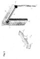
- FIGS. 1 to 9 show method steps for mounting a roller blind hanger 10 on a winding shaft 30 and a roller shutter door 1 mounted in this way.
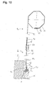
- FIGS. 10 to 12 show a first embodiment of a locking device 70 for locking / unlocking the roller shutter curtain 10.
- FIGS. 13 to 16 show a second embodiment of the aforementioned locking device 70.
- the roller shutter curtain 10 serves to close a door opening 2 present in a border 3, such as a wall section, for example.
- the roller shutter curtain 10 comprises a multiplicity of hinged rods 11 for forming a so-called roller shutter door.
- the roller shutter curtain at least partially consist of a film or other flexible material.
- This roll-up door curtain 10 or roller shutter body has in the lower end region a closing edge 13, in the upper end region a closing edge 12 and two side edges 14, 15.
- the closing edge 13 usually touches the bottom of the door opening 2.
- the closing edge 13 may for example also be formed instead of a rod 11 by a sealing profile or an anti-trap profile.
- the end edge 12 is located at the opposite end in the upper end region and extends generally parallel to the closing edge 13.
- the packaging unit 16 essentially comprises three packaging parts 17 with a plurality of compartments 18.
- a compartment 18 provided in the middle packaging part 17 in FIG. 1 serves to stow the two guide rails 20, 22 upper end of all three Packaging parts 17 is in each case a compartment 18 in the form of a recess for supporting the winding shaft 30.
- packaging part 17, located in the two lateral packaging parts 17 each have a compartment 18 for receiving the support brackets 24, 26th
- the roller blind curtain 10 is mounted in trough-like compartments 18 of the three packaging parts 17.
- at least the middle packing part 17 in the foot area comprises a further compartment 18, for example for receiving fastening means such as screws, nuts or the like.
- a plurality of cover elements of a lintel 28 are placed on top of the packaging unit 16, as shown in Fig. 1.
- the packaging unit 16 enables a compact and space-saving compilation of the required components and at the same time a separate removal of the components required in each case, without initially unneeded components must be removed in advance.
- the winding shaft 30, the guide rails 20, 22 and the support brackets 24, 26 are first removed from the corresponding packaging parts 17 and compartments 18 and placed on the floor in the area of the door opening 2. Then, the winding shaft 30 at its two ends in each case with a support bracket 24 and 26 are connected such that the winding shaft 30 is rotatably mounted. To the support brackets 24, 26, the guide rails 20, 22 are then mounted.
- This combination of guide rails 20, 22 and support brackets 24, 26 forms a support structure for the intended later use holding the winding shaft.
- the support structure 20, 22, 24, 26 is mounted with attached winding shaft 30 and positioned in the gate opening 2.
- this compilation can be fixed to the border 3 by means of conventional fastening means. After this installation, the winding shaft 30 is thus already in its intended for the operation position.
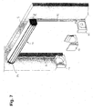
- the packaging unit 16 including the roller blind curtain 10 still located therein is positioned in the region of the door opening 2 below the winding shaft 30 (FIG. 4).
- a Montagezugstoff 40 is removed from the packaging unit 16 and connected to both the winding shaft 30 and with the roller blind curtain 10.
- the Montagezugstoff 40 has a first end 46 and a second end 48.
- fasteners 65, 66 are provided for fastening the straps 42, 44 on the winding shaft 30 and on the roller blind curtain 10.
- the two belt straps 42, 44 are fastened with their first end 46 equidistant from the two ends of the winding shaft 30 to the winding shaft 30.
- the second ends 48 of the straps 42, 44 are also attached at an end edge 12 of the roll-up curtain 10, each equally far from the side edges 14, 15 of the roll-up curtain 10 at the end edge 12.
- the attachment of the first end 46 and / or the second end 48 of the straps 42, 44 on the winding shaft 30 and / or on the roller blind curtain 10 are already carried out in advance in the factory and stored accordingly in the packaging unit 16.
- the Montagezugstoff 40 may include only a webbing or a wide web or more than two straps. These webbings or the at least one wider web are made of a flexible material which is suitable, on the one hand, to withstand the stresses occurring during assembly and, on the other hand, to be wound on superimposed windings or webs on the winding shaft 30.
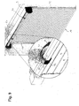
- the drive of the winding shaft 30 can be activated in order to pull up the roller shutter curtain 10 by means of the straps 42, 44 as an assembly aid (FIGS. 5 and 6).
- the straps 42, 44 wound in superimposed windings on the winding shaft 30.
- the roller blind curtain 10 is wound onto the winding shaft 30. This winding takes place until the last rod 11 in the region of the closing edge 13 is located approximately in the upper end region of the guide rails 20, 22.
- the lowest bar 11 can now be introduced with the closing edge 13 in the upper end region of the guide rails 20, 22 in this.
- the end areas can be equipped with appropriate threading aids or retrofitted.
- the fastening unit 60 comprises a U-profile 61 with fastening flanges 62, 63 connected to the two webs of the U-profile.
- Each of the fastening flanges 62, 63 has two recesses via which the fastening unit 60 can be fastened to the winding shaft 30 by means of screws or the like ,
- the dimensions of the fastening unit 60 are chosen such that the superposed windings of the webbing 42 are pressed against the winding shaft.
- the webbing 42, 44 to the winding shaft 30 pressing fastener 60 allows at least partially, preferably a total relief of the webbing 42, 44 in the later intended operation of the roller door 1.
- other fastening means may be provided, the permanent fixing of Montagezugstoffs 40, 42, 44 on the winding shaft 30 ensure.
- the straps 42, 44 Another advantage of the straps 42, 44 is that the wound webbings 42, 44 need not be subsequently removed, but at the same time can serve as a damping bearing rings during the winding or unwinding process.
- the choice of material of Montagezugstoffs 40 can be adjusted in advance to this later damping function.
- a corresponding number of straps can be selected as Montageoszugstoff.
- FIGS. 10 to 12 are each a cross-section through the above-described roller door 1 with the locking device 70 according to a first embodiment.
- the locking device 70 comprises a locking unit 80, a locking unit 90 and a spring unit 50.
- the spring unit 50 has a leaf spring 52 or 54 which is fixed with its first end 56 via the fixing unit 60 to the winding shaft 30 and is connected at its second end 58 to the locking unit 90. As already explained above, the fastening unit 60 at the same time fixes the straps 42, 44 on the winding shaft 30.
- the blocking unit comprises a locking hook 80 with a fastening section 81 fixed to the border 3 and a hook section 82 integrally connected to this fastening section 81, which protrudes at a predetermined angle from the fastening section 81 or the border 3.
- the locking unit 90 is rotatable about a horizontal axis extending parallel to the door opening 2 and at the same time serves as a connecting element between the second end 58 of the leaf spring 52 and the uppermost bar 11 of the roller blind 10.
- the locking unit 90 comprises a plurality of sections with a U-shaped groove 92 for engagement with the hook portion 82, a connecting member 94 for rotatably connecting to the uppermost rod 11 and a pivot pin 96 which is rotatably mounted in a loop of the second end 58 of the leaf spring 52.
- the locking unit as a result of the winding movement changed the bending of the leaf spring 52 from a locking position to an unlocking position and vice versa adjustable.
- the locking device 70 is located in the unlocked position with the roller door 1 opened or only partially opened, as shown in FIG. This distance A results in any case as a result of the leadership of the roller table hanger 10 in the guide rails 20, 22nd
- the locking unit 90 Only when the roller shutter curtain 10 is close or in the closed end position, as shown in FIGS. 11 and 12, the locking unit 90 is moved to the locking position. In this position, the uppermost rod 11 projects at least partially out of the upper end of the guide rail 20, 22. As a result of the partial winding of the leaf spring 52 on the winding shaft 30 and due to a distance B between the axis of rotation of the winding shaft 30 and the border 3, the leaf spring 52 undergoes a certain bend in this position and exerts a force F1 in the direction of the border 3 on the locking unit 90th and the upper end portion of the uppermost rod 11.
- the locking device 70 is provided as a blocking unit 85 via a holder 87 spaced from the border 3 arranged locking pin 86.
- the associated locking unit 100 is formed by a partially flexible connecting plate 100 with a recess 102, as shown in particular in FIG. 14. This connection plate 100 is rotatably articulated to the end edge 12 of the uppermost rod 11.
- the spring unit 50 which has already been described in connection with the first embodiment, in the form of a leaf spring 52 and a blocking element 110 in the form of a leaf spring 112 are also provided.
- the fastening unit 60 in turn fixes both the wound webbings 42, 44 and the leaf spring 52 on the winding shaft 30.
- the leaf spring 52 is fastened with its second end 58 to the connection plate 100.
- the portion of the leaf spring 52 between the mounting unit 60 and the terminal plate 100 serves to exert a force on the terminal plate 100 to pivot it in the direction of the border 3 and vice versa. This force is influenced both by the positional arrangement, the bending radius, the dimensions and by the movement of the winding shaft 30.
- the leaf spring 112 is fixed with its first end 114 via slots 118 by means of associated fastening means on the winding shaft 30.
- the elongated holes 118 can serve for the exact positioning of the leaf spring 112 on the winding shaft 30, so that the leaf spring 112 is displaceable in a suitable region, for example, without abutting the end edge 12.
- the second end 116 of the leaf spring 112 is via a guide 105 in the directions G according to the arrow in Fig. 13 movable to obstruct the recess 102 or release.
- the guide 105 comprises two L-profiles 106, 107, which are fastened to the connection plate 100.
- the leaf spring 112 can optionally be used only to block or release the recess 102 or in addition to exerting a force on the connection plate 100 in the direction of the border 3.
- the locking position in the region of the guide rail 22 shown in a perspective view in FIG. 13 is shown again in cross-section in FIG. 15.
- the unlocking position is shown in FIG. 16.
- the leaf spring 112 is in the locking position in a blocking position in which the second end 116, the recess 102 covered, so that the locking pin 85 can not pass through the recess 102.
- the roller blind curtain 10 can not be driven past the locking pin 85.
- the locking member 110 is in a release position in which the second end 116 is transferred due to a rotation of the winding shaft 30 of the leaf spring 112 in a recess 102 releasing position.
- Both the first and the second embodiment is characterized in that the leaf spring 52 is used as a result of the movement of the winding shaft 30 for adjusting the locking unit 90 from the locking position to the unlocked position and vice versa. Furthermore, the fixing unit 60 for fixing and unloading the wound around the winding shaft 30 Montagezugstoffs 40 and for fastening the Leaf spring 52 can be used.
- An advantage of the second embodiment is that the leaf spring 112 can reliably prevent an unauthorized opening attempt.
Landscapes
- Engineering & Computer Science (AREA)
- Structural Engineering (AREA)
- Architecture (AREA)
- Civil Engineering (AREA)
- Operating, Guiding And Securing Of Roll- Type Closing Members (AREA)
Applications Claiming Priority (1)
| Application Number | Priority Date | Filing Date | Title |
|---|---|---|---|
| DE200610046008 DE102006046008B3 (de) | 2006-09-28 | 2006-09-28 | Montageverfahren für Rolltor und ein solches Rolltor |
Publications (3)
| Publication Number | Publication Date |
|---|---|
| EP1908915A2 true EP1908915A2 (fr) | 2008-04-09 |
| EP1908915A3 EP1908915A3 (fr) | 2010-12-15 |
| EP1908915B1 EP1908915B1 (fr) | 2016-11-30 |
Family
ID=38984170
Family Applications (1)
| Application Number | Title | Priority Date | Filing Date |
|---|---|---|---|
| EP07116018.8A Active EP1908915B1 (fr) | 2006-09-28 | 2007-09-10 | Procédé de montage pour une porte à enroulement |
Country Status (2)
| Country | Link |
|---|---|
| EP (1) | EP1908915B1 (fr) |
| DE (1) | DE102006046008B3 (fr) |
Cited By (1)
| Publication number | Priority date | Publication date | Assignee | Title |
|---|---|---|---|---|
| US12024946B2 (en) | 2020-04-06 | 2024-07-02 | Levolor, Inc. | Shade adapter for a roller shade |
Families Citing this family (3)
| Publication number | Priority date | Publication date | Assignee | Title |
|---|---|---|---|---|
| DE102009019985B4 (de) | 2008-10-22 | 2019-04-18 | A.R.T. Systemtechnik GmbH & Co. KG | System zum Aufrollen von Verschlüssen für Gebäudeöffnungen |
| DE202009017783U1 (de) | 2009-05-06 | 2010-08-12 | Palm, Frank | System zum Aufrollen von Verschlüssen für Gebäudeöffnungen |
| DE102010031733A1 (de) | 2010-07-21 | 2012-01-26 | Hörmann KG Antriebstechnik | Montageverfahren und Montagehilfsgerät für ein Rolltor |
Citations (3)
| Publication number | Priority date | Publication date | Assignee | Title |
|---|---|---|---|---|
| EP0238944A2 (fr) | 1986-03-27 | 1987-09-30 | HàRmann Kg Bielefeld | Appareil de montage |
| DE10127015A1 (de) | 2001-01-12 | 2002-07-18 | Hoermann Kg Dissen | Montagevorrichtung zum Anheben eines Panzers eines Rolltors sowie Verwendung derselben |
| DE102004003067A1 (de) | 2003-04-03 | 2004-10-14 | Klenk, Gottlieb | Vorrichtung zum Verbinden eines Rollvorhangs mit einer Wickelwelle |
Family Cites Families (5)
| Publication number | Priority date | Publication date | Assignee | Title |
|---|---|---|---|---|
| US4251039A (en) * | 1979-07-30 | 1981-02-17 | Douglas Howard | Rolling door curtain mounting apparatus |
| DE10159419A1 (de) * | 2001-12-04 | 2003-06-12 | Hoermann Kg Verkaufsges | Rolltor |
| EP1336717A3 (fr) * | 2002-02-14 | 2004-03-03 | Hörmann Kg Dissen | Porte enroulable |
| DE20315243U1 (de) * | 2003-10-02 | 2003-12-11 | Warema Renkhoff Gmbh | Montagehilfsvorrichtung für Sonnenschutzanlagen o.dgl. |
| DE202005007744U1 (de) * | 2005-05-18 | 2005-07-21 | Gollnast System-Anlagen Gmbh | Verriegelungssystem für Rolläden, Rolltore u.dgl. |
-
2006
- 2006-09-28 DE DE200610046008 patent/DE102006046008B3/de not_active Expired - Fee Related
-
2007
- 2007-09-10 EP EP07116018.8A patent/EP1908915B1/fr active Active
Patent Citations (3)
| Publication number | Priority date | Publication date | Assignee | Title |
|---|---|---|---|---|
| EP0238944A2 (fr) | 1986-03-27 | 1987-09-30 | HàRmann Kg Bielefeld | Appareil de montage |
| DE10127015A1 (de) | 2001-01-12 | 2002-07-18 | Hoermann Kg Dissen | Montagevorrichtung zum Anheben eines Panzers eines Rolltors sowie Verwendung derselben |
| DE102004003067A1 (de) | 2003-04-03 | 2004-10-14 | Klenk, Gottlieb | Vorrichtung zum Verbinden eines Rollvorhangs mit einer Wickelwelle |
Cited By (1)
| Publication number | Priority date | Publication date | Assignee | Title |
|---|---|---|---|---|
| US12024946B2 (en) | 2020-04-06 | 2024-07-02 | Levolor, Inc. | Shade adapter for a roller shade |
Also Published As
| Publication number | Publication date |
|---|---|
| EP1908915B1 (fr) | 2016-11-30 |
| DE102006046008B3 (de) | 2008-04-30 |
| EP1908915A3 (fr) | 2010-12-15 |
Similar Documents
| Publication | Publication Date | Title |
|---|---|---|
| DE102007063705B4 (de) | Rollo mit Lochbandantrieb | |
| EP1970235B1 (fr) | Store de fenêtre latérale doté d'un entraînement à corde | |
| EP0648913B1 (fr) | Dispositif de sécurité pour un volet à rouleau constitué par des lattes | |
| DE4104749C2 (de) | Rolladen | |
| WO2012095324A1 (fr) | Agencement de volet pliant comprenant plusieurs éléments rigides dotes, en particulier, de bords infléchissants et non infléchissants en alternance | |
| DE69219654T2 (de) | Ausgleichvorrichtung für aufrollbare Tore mit variabler Geschwindigkeit | |
| WO2011003576A2 (fr) | Dispositif à enroulement pour l'occlusion d'ouvertures pratiquées dans des murs ou de fenêtres | |
| DE3245009A1 (de) | Rolltor | |
| EP1908915B1 (fr) | Procédé de montage pour une porte à enroulement | |
| EP2634341A2 (fr) | Porte accordéon avec deux éléments de volet pliant rigides en soi dotés de bords infléchissants et non infléchissants en alternance et dispositif d'actionnement correspondant | |
| EP2535501B1 (fr) | Dispositif d'ombrage de bâtiments doté de rails de guidage pouvant être sortis | |
| WO2005082656A1 (fr) | Porte d'automobile comprenant plusieurs composants reglables | |
| EP3695081B1 (fr) | Élément de porte inférieur comportant un support à rouleau pivotant | |
| EP1366259B1 (fr) | Porte sectionnee | |
| EP2565360B1 (fr) | Dispositif de fixation d'un store sur un cylindre d'enroulement | |
| DE69822414T2 (de) | Fangvorrichtung für rollbare Verschlussvorrichtungen | |
| DE19903008C2 (de) | Rolladen | |
| EP1577485B1 (fr) | Volet roulant | |
| DE60000135T2 (de) | Sicherheitsvorrichtung gegen das Hochschieben von Rolläden | |
| EP0383067A1 (fr) | Volet roulant pour ouvertures dans les toitures ou les murs, particulièrement avec une fenêtre de toiture basculante | |
| DE102005037775A1 (de) | Jalousierbarer Rollladen | |
| DE29801334U1 (de) | Rolladensicherung | |
| DE102020127200B3 (de) | Rolladen zum Verschließen und/oder Abdunkeln einer Gebäudeöffnung sowie Verfahren zum Öffnen einer Gebäudeöffnung | |
| DE102006046010A1 (de) | Verriegelungsvorrichtung für ein Rolltor und ein solches Rolltor | |
| EP1972477A2 (fr) | Store de fenêtre latérale doté d'une barre de traction à charnière et d'une barre de support carrée |
Legal Events
| Date | Code | Title | Description |
|---|---|---|---|
| PUAI | Public reference made under article 153(3) epc to a published international application that has entered the european phase |
Free format text: ORIGINAL CODE: 0009012 |
|
| AK | Designated contracting states |
Kind code of ref document: A2 Designated state(s): AT BE BG CH CY CZ DE DK EE ES FI FR GB GR HU IE IS IT LI LT LU LV MC MT NL PL PT RO SE SI SK TR |
|
| AX | Request for extension of the european patent |
Extension state: AL BA HR MK RS |
|
| PUAL | Search report despatched |
Free format text: ORIGINAL CODE: 0009013 |
|
| AK | Designated contracting states |
Kind code of ref document: A3 Designated state(s): AT BE BG CH CY CZ DE DK EE ES FI FR GB GR HU IE IS IT LI LT LU LV MC MT NL PL PT RO SE SI SK TR |
|
| AX | Request for extension of the european patent |
Extension state: AL BA HR MK RS |
|
| 17P | Request for examination filed |
Effective date: 20110610 |
|
| AKX | Designation fees paid |
Designated state(s): AT CH DE LI |
|
| 17Q | First examination report despatched |
Effective date: 20130611 |
|
| GRAP | Despatch of communication of intention to grant a patent |
Free format text: ORIGINAL CODE: EPIDOSNIGR1 |
|
| RIC1 | Information provided on ipc code assigned before grant |
Ipc: E06B 9/80 20060101ALN20160503BHEP Ipc: E06B 9/17 20060101AFI20160503BHEP Ipc: E06B 9/58 20060101ALN20160503BHEP Ipc: E06B 9/86 20060101ALN20160503BHEP Ipc: E06B 9/171 20060101ALN20160503BHEP |
|
| INTG | Intention to grant announced |
Effective date: 20160525 |
|
| GRAS | Grant fee paid |
Free format text: ORIGINAL CODE: EPIDOSNIGR3 |
|
| GRAA | (expected) grant |
Free format text: ORIGINAL CODE: 0009210 |
|
| AK | Designated contracting states |
Kind code of ref document: B1 Designated state(s): AT CH DE LI |
|
| REG | Reference to a national code |
Ref country code: CH Ref legal event code: EP |
|
| REG | Reference to a national code |
Ref country code: CH Ref legal event code: NV Representative=s name: BRAUNPAT BRAUN EDER AG, CH Ref country code: AT Ref legal event code: REF Ref document number: 849983 Country of ref document: AT Kind code of ref document: T Effective date: 20161215 |
|
| REG | Reference to a national code |
Ref country code: DE Ref legal event code: R096 Ref document number: 502007015291 Country of ref document: DE |
|
| REG | Reference to a national code |
Ref country code: DE Ref legal event code: R097 Ref document number: 502007015291 Country of ref document: DE |
|
| PLBE | No opposition filed within time limit |
Free format text: ORIGINAL CODE: 0009261 |
|
| STAA | Information on the status of an ep patent application or granted ep patent |
Free format text: STATUS: NO OPPOSITION FILED WITHIN TIME LIMIT |
|
| 26N | No opposition filed |
Effective date: 20170831 |
|
| REG | Reference to a national code |
Ref country code: CH Ref legal event code: PCAR Free format text: NEW ADDRESS: HOLEESTRASSE 87, 4054 BASEL (CH) |
|
| PGFP | Annual fee paid to national office [announced via postgrant information from national office to epo] |
Ref country code: AT Payment date: 20180918 Year of fee payment: 12 Ref country code: CH Payment date: 20180924 Year of fee payment: 12 |
|
| REG | Reference to a national code |
Ref country code: CH Ref legal event code: PL |
|
| PG25 | Lapsed in a contracting state [announced via postgrant information from national office to epo] |
Ref country code: LI Free format text: LAPSE BECAUSE OF NON-PAYMENT OF DUE FEES Effective date: 20190930 Ref country code: CH Free format text: LAPSE BECAUSE OF NON-PAYMENT OF DUE FEES Effective date: 20190930 |
|
| REG | Reference to a national code |
Ref country code: AT Ref legal event code: MM01 Ref document number: 849983 Country of ref document: AT Kind code of ref document: T Effective date: 20190910 |
|
| PG25 | Lapsed in a contracting state [announced via postgrant information from national office to epo] |
Ref country code: AT Free format text: LAPSE BECAUSE OF NON-PAYMENT OF DUE FEES Effective date: 20190910 |
|
| P01 | Opt-out of the competence of the unified patent court (upc) registered |
Effective date: 20230502 |
|
| REG | Reference to a national code |
Ref country code: DE Ref legal event code: R082 Ref document number: 502007015291 Country of ref document: DE Representative=s name: KASTEL PATENTANWAELTE PARTG MBB, DE |
|
| PGFP | Annual fee paid to national office [announced via postgrant information from national office to epo] |
Ref country code: DE Payment date: 20251118 Year of fee payment: 19 |