EP1908915A2 - Assembly method for a rolling gate - Google Patents
Assembly method for a rolling gate Download PDFInfo
- Publication number
- EP1908915A2 EP1908915A2 EP07116018A EP07116018A EP1908915A2 EP 1908915 A2 EP1908915 A2 EP 1908915A2 EP 07116018 A EP07116018 A EP 07116018A EP 07116018 A EP07116018 A EP 07116018A EP 1908915 A2 EP1908915 A2 EP 1908915A2
- Authority
- EP
- European Patent Office
- Prior art keywords
- winding shaft
- roller
- curtain
- montagezugmittel
- wound
- Prior art date
- Legal status (The legal status is an assumption and is not a legal conclusion. Google has not performed a legal analysis and makes no representation as to the accuracy of the status listed.)
- Granted
Links
Images


Classifications
-
- E—FIXED CONSTRUCTIONS
- E06—DOORS, WINDOWS, SHUTTERS, OR ROLLER BLINDS IN GENERAL; LADDERS
- E06B—FIXED OR MOVABLE CLOSURES FOR OPENINGS IN BUILDINGS, VEHICLES, FENCES OR LIKE ENCLOSURES IN GENERAL, e.g. DOORS, WINDOWS, BLINDS, GATES
- E06B9/00—Screening or protective devices for wall or similar openings, with or without operating or securing mechanisms; Closures of similar construction
- E06B9/02—Shutters, movable grilles, or other safety closing devices, e.g. against burglary
- E06B9/08—Roll-type closures
- E06B9/11—Roller shutters
- E06B9/17—Parts or details of roller shutters, e.g. suspension devices, shutter boxes, wicket doors, ventilation openings
-
- E—FIXED CONSTRUCTIONS
- E06—DOORS, WINDOWS, SHUTTERS, OR ROLLER BLINDS IN GENERAL; LADDERS
- E06B—FIXED OR MOVABLE CLOSURES FOR OPENINGS IN BUILDINGS, VEHICLES, FENCES OR LIKE ENCLOSURES IN GENERAL, e.g. DOORS, WINDOWS, BLINDS, GATES
- E06B9/00—Screening or protective devices for wall or similar openings, with or without operating or securing mechanisms; Closures of similar construction
- E06B9/56—Operating, guiding or securing devices or arrangements for roll-type closures; Spring drums; Tape drums; Counterweighting arrangements therefor
- E06B9/80—Safety measures against dropping or unauthorised opening; Braking or immobilising devices; Devices for limiting unrolling
- E06B2009/801—Locking arrangements
- E06B2009/802—Locking arrangements located in or close to shutter box
-
- E—FIXED CONSTRUCTIONS
- E06—DOORS, WINDOWS, SHUTTERS, OR ROLLER BLINDS IN GENERAL; LADDERS
- E06B—FIXED OR MOVABLE CLOSURES FOR OPENINGS IN BUILDINGS, VEHICLES, FENCES OR LIKE ENCLOSURES IN GENERAL, e.g. DOORS, WINDOWS, BLINDS, GATES
- E06B9/00—Screening or protective devices for wall or similar openings, with or without operating or securing mechanisms; Closures of similar construction
- E06B9/02—Shutters, movable grilles, or other safety closing devices, e.g. against burglary
- E06B9/08—Roll-type closures
- E06B9/11—Roller shutters
- E06B9/17—Parts or details of roller shutters, e.g. suspension devices, shutter boxes, wicket doors, ventilation openings
- E06B9/171—Rollers therefor; Fastening roller shutters to rollers
-
- E—FIXED CONSTRUCTIONS
- E06—DOORS, WINDOWS, SHUTTERS, OR ROLLER BLINDS IN GENERAL; LADDERS
- E06B—FIXED OR MOVABLE CLOSURES FOR OPENINGS IN BUILDINGS, VEHICLES, FENCES OR LIKE ENCLOSURES IN GENERAL, e.g. DOORS, WINDOWS, BLINDS, GATES
- E06B9/00—Screening or protective devices for wall or similar openings, with or without operating or securing mechanisms; Closures of similar construction
- E06B9/56—Operating, guiding or securing devices or arrangements for roll-type closures; Spring drums; Tape drums; Counterweighting arrangements therefor
- E06B9/58—Guiding devices
-
- E—FIXED CONSTRUCTIONS
- E06—DOORS, WINDOWS, SHUTTERS, OR ROLLER BLINDS IN GENERAL; LADDERS
- E06B—FIXED OR MOVABLE CLOSURES FOR OPENINGS IN BUILDINGS, VEHICLES, FENCES OR LIKE ENCLOSURES IN GENERAL, e.g. DOORS, WINDOWS, BLINDS, GATES
- E06B9/00—Screening or protective devices for wall or similar openings, with or without operating or securing mechanisms; Closures of similar construction
- E06B9/56—Operating, guiding or securing devices or arrangements for roll-type closures; Spring drums; Tape drums; Counterweighting arrangements therefor
- E06B9/80—Safety measures against dropping or unauthorised opening; Braking or immobilising devices; Devices for limiting unrolling
- E06B9/82—Safety measures against dropping or unauthorised opening; Braking or immobilising devices; Devices for limiting unrolling automatic
- E06B9/86—Safety measures against dropping or unauthorised opening; Braking or immobilising devices; Devices for limiting unrolling automatic against unauthorised opening
Definitions
- the present invention relates to a method for mounting a roller blind curtain on a winding shaft for a roller door.
- roller shutter curtain is understood to mean a roller shutter formed from a multiplicity of rods which are guided against one another, but also a curtain in the form of a foil or the like.
- open end position is understood to mean the end position of the roller shutter curtain at the end of the opening movement.
- closing end position is the end position at the end of the closing movement. In the final closing position, the door opening to be closed is completely closed.
- the invention has for its object to provide a method for assembling a roller shutter, in which little installation aids and low installation costs are required. Furthermore, such a roller shutter should be specified.
- the roller shutter is pulled by Montagezugstoffn up. This is done by winding the Montagezugschs on the winding shaft by the winding will is rotated. This can be done very easily via a later serving for the operation of the roller shutter drive motor which drives the winding shaft.
- the Winding shaft turned further, so as to wind up the roller blind curtain on the winding shaft.
- the Montagezugstoff is therefore preferably wound on that axial region of the winding shaft, which also serves to receive the Rolltorbehanges.
- a roll-up door with a roll-up door curtain that can be wound up and unwound on a winding shaft is the subject of the independent claim.
- An idea of the invention is therefore first to position the winding shaft without wound on it roller shutter curtain at its intended end position for later operation of the roller door and rotatably mounted and then to position the roller shutter curtain in the door opening area, primarily on the ground below the winding shaft.
- the Montageipposzugstoff is attached to the roller table curtain and on the winding shaft, wherein the Montagezugstoff preferably consists of at least two straps.
- the Montagezugstoff can then be wound on the winding shaft first.
- the roller blind curtain is wound onto the winding shaft.
- the direction of rotation of the winding shaft is reversed to unwind the Rolltorbehang of the winding shaft and thereby threading the side edges of the roller table curtain in guide rails can.
- the assembly traction means and thus the roller blind curtain are then fastened to the winding shaft by means of a fastening unit.
- This attachment can alternatively be done before the threading of the roller table curtain in the guide rails, for example, immediately before the first winding of the raised by the Montagezugstoff roller blind curtain.
- the method according to the invention can be completely dispensed with the use of heavy lifting equipment, such as a mobile crane.
- heavy lifting equipment such as a mobile crane.
- two guide rails are each connected to a support bracket for the winding shaft and the winding shaft rotatably mounted on the support brackets in step a) as a support structure.
- the attachment of each support bracket to a guide rail can be done in a simple manner, in particular by plugging and screwing. Subsequently, the winding shaft between the two support brackets can be installed rotatably mounted.
- a support structure can advantageously be assembled, for example, lying on the floor and then lifted into the vertical position and attached to the border surrounding the door opening.
- step c) that is, in the positioning of the roller blind curtain in the region of the opening, the roller blind curtain is placed on the floor in front of the opening. It is advantageous if the roller shutter curtain is still positioned in a packaging unit together with the packaging in the region of the opening. The roller blind curtain can then be wound out of the packaging unit by means of the Montagezugstoffs on the winding shaft. Thus, it is not necessary to raise the roller shutter curtain by means of a hoist and to attach to the support brackets or the guide rails.
- the packaging itself can be with Sliding guides must be provided, which gently guide the roller blind curtain out of the packaging when it is pulled up.
- roller blind curtain For transporting the roller blind curtain is preferably stored in the package, that after opening the packaging, first the upper end portion of the roller blind curtain, which is to be wound on the winding shaft first, is accessible.
- the roller blind curtain is therefore preferably stored wrapped in the packaging in the opposite direction than later in operation on the winding shaft.
- the roller blind curtain wraps out of this position out of the packaging and is thereby guided on the sliding guides.
- a gentle intermediate layer may be present between the individual layers of wrapped in the packaging Rolltorbehanges, which is disposable after installation of the roll-up door.
- the second end of the Montagezugstoffs is attached to an end edge of the roller table curtain in step d).
- This end edge lies opposite the closing edge of the roller table curtain.
- a recess, a tab or other fastening elements can be selected in the region of the end edge.
- At least two straps are attached as Montagezugstoff.
- two straps are fastened at the same distance from the two ends of the winding shaft in order to achieve a symmetrical arrangement and thereby a symmetrical pulling up of the roller shutter curtain.
- even more straps can be provided as Montagezugstoff, which contributes to a further improvement of the below-described damping properties. In principle, however, only one webbing can be used.
- the Montagezugstoff is wound in step e) in superposed windings on the winding shaft.
- This not only serves the symmetrical pulling up of the roller table curtain, but also that the spaced positioning generated in each case by the superimposed webs in the region of the straps is uniform with respect to the roller shutter curtain, so that a symmetrical load occurs during operation. In addition, this causes a uniform damping. Furthermore, it facilitates the attachment of the fastening unit.
- the Montagezugstoff is fixed in its fully wound position by means of the attachment unit to the winding shaft.
- the attachment unit to the winding shaft.
- an urging device which urges the upper end portion of the roller shutter curtain in the closing end position of the roller shutter radially away from the winding shaft.
- such a squeezing device can also serve to support a push-on protection by the upper end portion is urged in the direction of the opening boundary in the unloaded state and there in an attempt to postpone the Rolltorbehang up, can hook on an abutment, wherein upon rotation of the Winding shaft in the opening movement direction, the upper end edge is pulled radially towards the winding shaft and so from the position in which the slip-on can act is pulled.
- the urging device may in particular be formed by a spring unit which is connected between the winding shaft and the roller table curtain and in particular between the behang solutionen end of the Montagezugstoffs and the roller blind curtain is arranged.
- a first end of a spring unit can be connected via the fastening unit to the second end of the assembly traction device and a second end of the spring unit to the roller basket curtain, the assembly traction means are wound on the winding shaft and fastened to the winding shaft by means of the fastening unit.
- the spring unit as well as the Montagezugstoff can be fixed in advance on the roller blind curtain and / or on the winding shaft, that is, with only one end or with both ends. This leads to a further simplification and reduces the assembly effort again.
- the Montagezugstoff can be accommodated with it connected spring unit wound on the winding shaft in the above-mentioned packaging unit. In this way, the process steps required for assembly are reduced on site and are also further simplified, so that incorrect installation can be largely excluded.
- the spring unit comprises at least one leaf spring.
- the spring unit is attached directly or indirectly via the Montagezugstoff to the winding shaft.
- the closing edge of the roller shutter curtain can be inserted into the roll cover Guides inserted and the roller shutter curtain is unwound for insertion into the guide rails of the winding shaft.
- an insertion aid can be provided in the upper end region of the guide rails or can already be pre-installed on the guide rails.
- the roller shutter according to the invention is provided with a roll-up on a winding shaft and unwound Rolltorbehang, wherein the roller blind curtain is connected via a Montagezugstoff with the winding shaft.
- This Montagezugstoff is preferably connected to the method according to the invention with the winding shaft and remains after performing the assembly permanently on the winding shaft.
- several straps are used as Montageangeszugstoff.
- the Montageyakstoff in the wound state serves as a spacer and / or support ring. Subsequent disassembly of the Montagezugstoffs deleted. In this way, a winding shaft arrangement with damping is made possible. This has an advantageous effect on the life of the winding shaft and roller blind curtain.
- the Montagezugstoff is connected via a fastening unit with the winding shaft.
- This connection of Montagezugstoff and mounting unit can already be made in advance, so that a relevant installation on site is eliminated.
- the fastening unit is used for fixing the Montagezugstoffs in the wound state and / or for attachment of the roller table curtain on the winding shaft.
- the Montagezugstoff is wound in superimposed tracks on the winding shaft.
- the material and the dimensions of the Montagezugstoffs is thereby taking into account the desired function on the one hand as an assembly tool during assembly and on the other hand at the same time as Supporting and / or spacing unit dimensioned and dimensioned for the remainder of the service life after installation.
- the length of the assembly traction means corresponds to at least half the length of the roll-up roller blind pull-up, preferably at least three quarters of this length and more particularly approximately this length or more than this length, so that the largest possible proportion of Rolltorbehanges can be pulled up here by means of the assembly aid.
- the Montagezugstoff is connected via a spring unit with the roller blind curtain.
- the spring unit is preferably designed as a leaf spring and can also cooperate with a locking device or be part of it.
- a locking device comprises a locking unit and a locking unit and is used for locking / unlocking the movable from a Offenend ein in a closing end position roller blind, wherein the locking unit locks the locking unit in the locking position of a movement of the roller blind curtain from the Sch technicallydwolf in the direction of the Offenend ein and in the Release unlocking position.
- the spring unit is for applying a force on the locking unit with this in operative connection, so that the locking unit from the locking position to the unlocked position and vice versa adjustable, wherein the outgoing of the spring unit force is variable to the locking unit by the movement of the winding shaft.
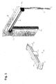
- FIGS. 1 to 9 show method steps for mounting a roller blind hanger 10 on a winding shaft 30 and a roller shutter door 1 mounted in this way.
- FIGS. 10 to 12 show a first embodiment of a locking device 70 for locking / unlocking the roller shutter curtain 10.
- FIGS. 13 to 16 show a second embodiment of the aforementioned locking device 70.
- the roller shutter curtain 10 serves to close a door opening 2 present in a border 3, such as a wall section, for example.
- the roller shutter curtain 10 comprises a multiplicity of hinged rods 11 for forming a so-called roller shutter door.
- the roller shutter curtain at least partially consist of a film or other flexible material.
- This roll-up door curtain 10 or roller shutter body has in the lower end region a closing edge 13, in the upper end region a closing edge 12 and two side edges 14, 15.
- the closing edge 13 usually touches the bottom of the door opening 2.
- the closing edge 13 may for example also be formed instead of a rod 11 by a sealing profile or an anti-trap profile.
- the end edge 12 is located at the opposite end in the upper end region and extends generally parallel to the closing edge 13.
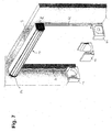
- the packaging unit 16 essentially comprises three packaging parts 17 with a plurality of compartments 18.
- a compartment 18 provided in the middle packaging part 17 in FIG. 1 serves to stow the two guide rails 20, 22 upper end of all three Packaging parts 17 is in each case a compartment 18 in the form of a recess for supporting the winding shaft 30.
- packaging part 17, located in the two lateral packaging parts 17 each have a compartment 18 for receiving the support brackets 24, 26th
- the roller blind curtain 10 is mounted in trough-like compartments 18 of the three packaging parts 17.
- at least the middle packing part 17 in the foot area comprises a further compartment 18, for example for receiving fastening means such as screws, nuts or the like.
- a plurality of cover elements of a lintel 28 are placed on top of the packaging unit 16, as shown in Fig. 1.
- the packaging unit 16 enables a compact and space-saving compilation of the required components and at the same time a separate removal of the components required in each case, without initially unneeded components must be removed in advance.
- the winding shaft 30, the guide rails 20, 22 and the support brackets 24, 26 are first removed from the corresponding packaging parts 17 and compartments 18 and placed on the floor in the area of the door opening 2. Then, the winding shaft 30 at its two ends in each case with a support bracket 24 and 26 are connected such that the winding shaft 30 is rotatably mounted. To the support brackets 24, 26, the guide rails 20, 22 are then mounted.
- This combination of guide rails 20, 22 and support brackets 24, 26 forms a support structure for the intended later use holding the winding shaft.
- the support structure 20, 22, 24, 26 is mounted with attached winding shaft 30 and positioned in the gate opening 2.
- this compilation can be fixed to the border 3 by means of conventional fastening means. After this installation, the winding shaft 30 is thus already in its intended for the operation position.
- the packaging unit 16 including the roller blind curtain 10 still located therein is positioned in the region of the door opening 2 below the winding shaft 30 (FIG. 4).
- a Montagezugstoff 40 is removed from the packaging unit 16 and connected to both the winding shaft 30 and with the roller blind curtain 10.
- the Montagezugstoff 40 has a first end 46 and a second end 48.
- fasteners 65, 66 are provided for fastening the straps 42, 44 on the winding shaft 30 and on the roller blind curtain 10.
- the two belt straps 42, 44 are fastened with their first end 46 equidistant from the two ends of the winding shaft 30 to the winding shaft 30.
- the second ends 48 of the straps 42, 44 are also attached at an end edge 12 of the roll-up curtain 10, each equally far from the side edges 14, 15 of the roll-up curtain 10 at the end edge 12.
- the attachment of the first end 46 and / or the second end 48 of the straps 42, 44 on the winding shaft 30 and / or on the roller blind curtain 10 are already carried out in advance in the factory and stored accordingly in the packaging unit 16.
- the Montagezugstoff 40 may include only a webbing or a wide web or more than two straps. These webbings or the at least one wider web are made of a flexible material which is suitable, on the one hand, to withstand the stresses occurring during assembly and, on the other hand, to be wound on superimposed windings or webs on the winding shaft 30.
- the drive of the winding shaft 30 can be activated in order to pull up the roller shutter curtain 10 by means of the straps 42, 44 as an assembly aid (FIGS. 5 and 6).
- the straps 42, 44 wound in superimposed windings on the winding shaft 30.
- the roller blind curtain 10 is wound onto the winding shaft 30. This winding takes place until the last rod 11 in the region of the closing edge 13 is located approximately in the upper end region of the guide rails 20, 22.
- the lowest bar 11 can now be introduced with the closing edge 13 in the upper end region of the guide rails 20, 22 in this.
- the end areas can be equipped with appropriate threading aids or retrofitted.
- the fastening unit 60 comprises a U-profile 61 with fastening flanges 62, 63 connected to the two webs of the U-profile.
- Each of the fastening flanges 62, 63 has two recesses via which the fastening unit 60 can be fastened to the winding shaft 30 by means of screws or the like ,
- the dimensions of the fastening unit 60 are chosen such that the superposed windings of the webbing 42 are pressed against the winding shaft.
- the webbing 42, 44 to the winding shaft 30 pressing fastener 60 allows at least partially, preferably a total relief of the webbing 42, 44 in the later intended operation of the roller door 1.
- other fastening means may be provided, the permanent fixing of Montagezugstoffs 40, 42, 44 on the winding shaft 30 ensure.
- the straps 42, 44 Another advantage of the straps 42, 44 is that the wound webbings 42, 44 need not be subsequently removed, but at the same time can serve as a damping bearing rings during the winding or unwinding process.
- the choice of material of Montagezugstoffs 40 can be adjusted in advance to this later damping function.
- a corresponding number of straps can be selected as Montageoszugstoff.
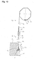
- FIGS. 10 to 12 are each a cross-section through the above-described roller door 1 with the locking device 70 according to a first embodiment.
- the locking device 70 comprises a locking unit 80, a locking unit 90 and a spring unit 50.
- the spring unit 50 has a leaf spring 52 or 54 which is fixed with its first end 56 via the fixing unit 60 to the winding shaft 30 and is connected at its second end 58 to the locking unit 90. As already explained above, the fastening unit 60 at the same time fixes the straps 42, 44 on the winding shaft 30.
- the blocking unit comprises a locking hook 80 with a fastening section 81 fixed to the border 3 and a hook section 82 integrally connected to this fastening section 81, which protrudes at a predetermined angle from the fastening section 81 or the border 3.
- the locking unit 90 is rotatable about a horizontal axis extending parallel to the door opening 2 and at the same time serves as a connecting element between the second end 58 of the leaf spring 52 and the uppermost bar 11 of the roller blind 10.
- the locking unit 90 comprises a plurality of sections with a U-shaped groove 92 for engagement with the hook portion 82, a connecting member 94 for rotatably connecting to the uppermost rod 11 and a pivot pin 96 which is rotatably mounted in a loop of the second end 58 of the leaf spring 52.
- the locking unit as a result of the winding movement changed the bending of the leaf spring 52 from a locking position to an unlocking position and vice versa adjustable.
- the locking device 70 is located in the unlocked position with the roller door 1 opened or only partially opened, as shown in FIG. This distance A results in any case as a result of the leadership of the roller table hanger 10 in the guide rails 20, 22nd
- the locking unit 90 Only when the roller shutter curtain 10 is close or in the closed end position, as shown in FIGS. 11 and 12, the locking unit 90 is moved to the locking position. In this position, the uppermost rod 11 projects at least partially out of the upper end of the guide rail 20, 22. As a result of the partial winding of the leaf spring 52 on the winding shaft 30 and due to a distance B between the axis of rotation of the winding shaft 30 and the border 3, the leaf spring 52 undergoes a certain bend in this position and exerts a force F1 in the direction of the border 3 on the locking unit 90th and the upper end portion of the uppermost rod 11.
- the locking device 70 is provided as a blocking unit 85 via a holder 87 spaced from the border 3 arranged locking pin 86.
- the associated locking unit 100 is formed by a partially flexible connecting plate 100 with a recess 102, as shown in particular in FIG. 14. This connection plate 100 is rotatably articulated to the end edge 12 of the uppermost rod 11.
- the spring unit 50 which has already been described in connection with the first embodiment, in the form of a leaf spring 52 and a blocking element 110 in the form of a leaf spring 112 are also provided.
- the fastening unit 60 in turn fixes both the wound webbings 42, 44 and the leaf spring 52 on the winding shaft 30.
- the leaf spring 52 is fastened with its second end 58 to the connection plate 100.
- the portion of the leaf spring 52 between the mounting unit 60 and the terminal plate 100 serves to exert a force on the terminal plate 100 to pivot it in the direction of the border 3 and vice versa. This force is influenced both by the positional arrangement, the bending radius, the dimensions and by the movement of the winding shaft 30.
- the leaf spring 112 is fixed with its first end 114 via slots 118 by means of associated fastening means on the winding shaft 30.
- the elongated holes 118 can serve for the exact positioning of the leaf spring 112 on the winding shaft 30, so that the leaf spring 112 is displaceable in a suitable region, for example, without abutting the end edge 12.
- the second end 116 of the leaf spring 112 is via a guide 105 in the directions G according to the arrow in Fig. 13 movable to obstruct the recess 102 or release.
- the guide 105 comprises two L-profiles 106, 107, which are fastened to the connection plate 100.
- the leaf spring 112 can optionally be used only to block or release the recess 102 or in addition to exerting a force on the connection plate 100 in the direction of the border 3.
- the locking position in the region of the guide rail 22 shown in a perspective view in FIG. 13 is shown again in cross-section in FIG. 15.
- the unlocking position is shown in FIG. 16.
- the leaf spring 112 is in the locking position in a blocking position in which the second end 116, the recess 102 covered, so that the locking pin 85 can not pass through the recess 102.
- the roller blind curtain 10 can not be driven past the locking pin 85.
- the locking member 110 is in a release position in which the second end 116 is transferred due to a rotation of the winding shaft 30 of the leaf spring 112 in a recess 102 releasing position.
- Both the first and the second embodiment is characterized in that the leaf spring 52 is used as a result of the movement of the winding shaft 30 for adjusting the locking unit 90 from the locking position to the unlocked position and vice versa. Furthermore, the fixing unit 60 for fixing and unloading the wound around the winding shaft 30 Montagezugstoffs 40 and for fastening the Leaf spring 52 can be used.
- An advantage of the second embodiment is that the leaf spring 112 can reliably prevent an unauthorized opening attempt.
Landscapes
- Engineering & Computer Science (AREA)
- Structural Engineering (AREA)
- Architecture (AREA)
- Civil Engineering (AREA)
- Operating, Guiding And Securing Of Roll- Type Closing Members (AREA)
Abstract
Description
Die vorliegende Erfindung betrifft ein Verfahren zur Montage eines Rolltorbehanges auf einer Wickelwelle für ein Rolltor.The present invention relates to a method for mounting a roller blind curtain on a winding shaft for a roller door.
Unter "Rolltorbehang" wird im Sinne der vorliegenden Erfindung ein aus einer Vielzahl von aneinander gelenkten Stäben gebildeter Rolltorpanzer, aber auch ein Behang in Form einer Folie oder dergleichen verstanden. Ferner wird unter dem Begriff "Offenendstellung" die Endstellung des Rolltorbehanges am Ende der Öffnungsbewegung verstanden. Die "Schließendstellung" ist die Endstellung am Ende der Schließbewegung. In der Schließendstellung ist die zu verschließende Toröffnung vollständig verschlossen.In the context of the present invention, "roller shutter curtain" is understood to mean a roller shutter formed from a multiplicity of rods which are guided against one another, but also a curtain in the form of a foil or the like. Furthermore, the term "open end position" is understood to mean the end position of the roller shutter curtain at the end of the opening movement. The "closing end position" is the end position at the end of the closing movement. In the final closing position, the door opening to be closed is completely closed.
Aus der
Gemäß der
Der Erfindung liegt die Aufgabe zugrunde, ein Verfahren zur Montage eines Rolltores anzugeben, bei dem wenig Montagehilfsmittel und ein geringer Montageaufwand erforderlich sind. Ferner soll ein solches Rolltor angegeben werden.The invention has for its object to provide a method for assembling a roller shutter, in which little installation aids and low installation costs are required. Furthermore, such a roller shutter should be specified.
Diese Aufgabe wird durch ein Verfahren mit den Schritten des Anspruches 1 bzw. ein Rolltor des Anspruches 1 bzw. ein Rolltor mit den Merkmalen des Anspruches 12 gelöst.This object is achieved by a method with the steps of claim 1 and a roller door of claim 1 and a roller shutter with the features of
Vorteilhafte Ausgestaltungen der Erfindung sind Gegenstand der Unteransprüche.Advantageous embodiments of the invention are the subject of the dependent claims.
Erfindungsgemäß wird demnach zunächst nur die Wickelwelle montiert, was aufgrunde des leichteren Gewichtes der Wickelwelle allein relativ einfach möglich ist. Auf die montierte Wickelwelle wird sodann der Rolltorpanzer mittels Montagezugmitteln nach oben gezogen. Dies erfolgt durch Aufwickeln des Montagezugmittels auf die Wickelwelle, indem die Wickelwille gedreht wird. Dies kann sehr einfach über einen später zum Betrieb des Rolltores dienenden Antriebsmotor geschehen, der die Wickelwelle antreibt. Nach dem Hochziehen des oberen Endbereiches des Rolltorbehanges wird die Wickelwelle weiter gedreht, um so den Rolltorbehang auf die Wickelwelle aufzuwickeln. Erfindungsgemäß ist dabei vorgesehen, dass das Montagezugmittel auf der Wickelwelle verbleibt. Es ist also nicht notwendig, das Montagezugmittel danach zu entfernen. Vielmehr kann gemäß einer besonders bevorzugten Ausgestaltung der Erfindung das Montagezugmittel als Zwischenlage zwischen Rolltorbehang und Wickelwelle dienen.According to the invention, therefore, initially only the winding shaft is mounted, which is due to the lighter weight of the winding shaft alone relatively easy. On the mounted winding shaft then the roller shutter is pulled by Montagezugmitteln up. This is done by winding the Montagezugmittels on the winding shaft by the winding will is rotated. This can be done very easily via a later serving for the operation of the roller shutter drive motor which drives the winding shaft. After pulling up the upper end portion of the roller table hanger is the Winding shaft turned further, so as to wind up the roller blind curtain on the winding shaft. According to the invention it is provided that the Montagezugmittel remains on the winding shaft. So it is not necessary to remove the Montagezugmittel then. Rather, according to a particularly preferred embodiment of the invention, the Montagezugmittel serve as an intermediate layer between Rolltorbehang and winding shaft.
Insbesondere, wenn zum Bilden des Montagezugmittels wenigstens zwei Gurte verwendet werden, die mit Abstand zueinander an der Wickelwelle angreifen, so können diese aufgewickelten Gurte als dämpfende Zwischenlage dienen, so dass der Lauf des Rolltores im späteren Betrieb ruhiger als bei Rolltoren nach dem Stand der Technik erfolgt.In particular, if at least two belts are used to form the Montagezugmittels attacking each other at a distance from the winding shaft, these wound belts can serve as a damping intermediate layer, so that the run of the rolling door in later operation quieter than in the case of rolling doors according to the prior art he follows.
Das Montagezugmittel wird demnach bevorzugt auf demjenigen axialen Bereich der Wickelwelle aufgewickelt, der auch zur Aufnahme des Rolltorbehanges dient.The Montagezugmittel is therefore preferably wound on that axial region of the winding shaft, which also serves to receive the Rolltorbehanges.
Eine besonders bevorzugte Verfahrensweise weist die folgenden Schritte auf:
- a) Befestigen der Wickelwelle an einer Tragkonstruktion zur im Betrieb vorgesehenen Halterung der Wickelwelle;
- b) Installieren von Wickelwelle und Tragkonstruktion an einer für den Betrieb vorgesehenen Endposition;
- c) Positionieren des Rolltorbehanges im Bereich der durch das Rolltor zu verschließenden Öffnung;
- d) Befestigen des Montagezugmittels mit einem ersten Ende an der Wickelwelle und mit einem zweiten Ende an einem oberen Ende des Rolltorbehanges;
- e) Aufwickeln des Montagezugmittels und des Rolltorbehanges auf die Wickelwelle, und
- f) Anordnen einer Befestigungseinheit zur Befestigung des Montagezugmittels und des Rolltorbehangs an der Wickelwelle.
- a) attaching the winding shaft to a supporting structure for the purpose of holding the winding shaft;
- b) installing the winding shaft and supporting structure at an end position intended for operation;
- c) positioning the roller table curtain in the area to be closed by the roller shutter opening;
- d) attaching the Montagezugmittels with a first end to the winding shaft and with a second end at an upper end of the Rolltorbehanges;
- e) winding the Montagezugmittels and the Rolltorbehanges on the winding shaft, and
- f) arranging a fastening unit for fastening the Montagezugmittels and the Rolltorbehangs on the winding shaft.
Ein Rolltor mit einem auf einer Wickelwelle auf- und abwickelbaren Rolltorbehang ist Gegenstand des Nebenanspruchs.A roll-up door with a roll-up door curtain that can be wound up and unwound on a winding shaft is the subject of the independent claim.
Eine Idee der Erfindung liegt demnach darin, zunächst die Wickelwelle ohne darauf aufgewickeltem Rolltorbehang an ihrer bestimmungsgemäßen Endposition zum späteren Betrieb des Rolltores zu positionieren und drehbar gelagert zu befestigen und anschließend den Rolltorbehang im Toröffnungsbereich, vorrangig auf dem Boden unterhalb der Wickelwelle, zu positionieren.An idea of the invention is therefore first to position the winding shaft without wound on it roller shutter curtain at its intended end position for later operation of the roller door and rotatably mounted and then to position the roller shutter curtain in the door opening area, primarily on the ground below the winding shaft.
Vorzugsweise wird erst das Montagehilfszugmittel an dem Rolltorbehang und an der Wickelwelle befestigt, wobei das Montagezugmittel bevorzugt aus wenigstens zwei Gurtbändern besteht. Nach Aktivierung des Wickelwellenantriebes oder auch durch manuelles Drehen der Wickelwelle oder auch durch manuelles Drehen der Wickelwelle kann dann zunächst das Montagezugmittel auf die Wickelwelle aufgewickelt werden. Im Anschluss daran wird der Rolltorbehang auf die Wickelwelle aufgewickelt. Nachfolgend wird die Drehrichtung der Wickelwelle reversiert, um den Rolltorbehang von der Wickelwelle abzuwickeln und hierbei die Seitenränder des Rolltorbehanges in Führungsschienen einfädeln zu können. Vorzugsweise in dem vollständig abgewickelten Zustand werden dann das Montagezugmittel und somit der Rolltorbehang mittels einer Befestigungseinheit an der Wickelwelle befestigt. Diese Befestigung kann alternativ auch vor dem Einfädeln des Rolltorbehanges in die Führungsschienen erfolgen, zum Beispiel unmittelbar vor dem ersten Aufwickeln des durch die Montagezugmittel hochgezogenen Rolltorbehanges.Preferably, only the Montagehilfszugmittel is attached to the roller table curtain and on the winding shaft, wherein the Montagezugmittel preferably consists of at least two straps. After activation of the winding shaft drive or by manually rotating the winding shaft or by manually rotating the winding shaft, the Montagezugmittel can then be wound on the winding shaft first. Subsequently, the roller blind curtain is wound onto the winding shaft. Subsequently, the direction of rotation of the winding shaft is reversed to unwind the Rolltorbehang of the winding shaft and thereby threading the side edges of the roller table curtain in guide rails can. Preferably, in the fully unwound state, the assembly traction means and thus the roller blind curtain are then fastened to the winding shaft by means of a fastening unit. This attachment can alternatively be done before the threading of the roller table curtain in the guide rails, for example, immediately before the first winding of the raised by the Montagezugmittel roller blind curtain.
Mit dem erfindungsgemäßen Verfahren kann auf den Einsatz von schweren Hubgeräten, wie beispielsweise einen mobilen Kran, vollständig verzichtet werden. Zudem ist es ebenfalls nicht erforderlich, vorübergehend Montagegerätschaften beispielsweise an den Tragkonsolen und etwaige separate Montagezugmittelantriebe vorzusehen. Darüber hinaus ist es nicht erforderlich, das Montagezugmittel nach Aufwickelung des Rolltorbehanges auf die Wickelwelle nachträglich zu entfernen. Es kann auf der Wickelwelle verbleiben und mittels der Befestigungseinheit fixiert bzw. von der Belastung durch den Rolltorbehang zumindest teilweise entlastet werden.With the method according to the invention can be completely dispensed with the use of heavy lifting equipment, such as a mobile crane. In addition, it is also not necessary to provide temporary mounting equipment, for example on the support brackets and any separate Montagezugmittelantriebe. In addition, it is not necessary to subsequently remove the Montagezugmittel after winding the Rolltorbehanges on the winding shaft. It can remain on the winding shaft and fixed by means of the fixing unit or be at least partially relieved of the burden of the roller blind curtain.
Bei einer bevorzugten Weiterbildung des Verfahrens werden im Schritt a) als Tragkonstruktion zwei Führungsschienen jeweils mit einer Tragkonsole für die Wickelwelle verbunden und die Wickelwelle an den Tragkonsolen drehbar gelagert befestigt. Die Befestigung je einer Tragkonsole an einer Führungsschiene kann auf einfache Weise insbesondere durch Aufstecken und Verschrauben erfolgen. Anschließend kann die Wickelwelle zwischen den beiden Tragkonsolen drehbar gelagert installiert werden. Eine solche Tragkonstruktion kann vorteilhafterweise beispielsweise auf dem Boden liegend zusammengebaut und anschließend in die senkrechte Position gehoben und an der die Toröffnung umgebenden Umrandung befestigt werden.In a preferred embodiment of the method, two guide rails are each connected to a support bracket for the winding shaft and the winding shaft rotatably mounted on the support brackets in step a) as a support structure. The attachment of each support bracket to a guide rail can be done in a simple manner, in particular by plugging and screwing. Subsequently, the winding shaft between the two support brackets can be installed rotatably mounted. Such a support structure can advantageously be assembled, for example, lying on the floor and then lifted into the vertical position and attached to the border surrounding the door opening.
Vorzugsweise wird im Schritt c), das heißt bei der Positionierung des Rolltorbehanges im Bereich der Öffnung, der Rolltorbehang auf dem Boden vor der Öffnung abgelegt. Von Vorteil ist dabei, wenn der Rolltorbehang noch in einer Verpackungseinheit liegend zusammen mit der Verpackung im Bereich der Öffnung positioniert wird. Der Rolltorbehang kann dann aus der Verpackungseinheit heraus mittels des Montagezugmittels auf die Wickelwelle gewickelt werden. Somit ist es nicht erforderlich, den Rolltorbehang mittels eines Hebezeugs anzuheben und an den Tragkonsolen oder den Führungsschienen zu befestigen. Die Verpackung selbst kann mit Gleitführungen versehen sein, die den Rolltorbehang schonend bei dessen Hochziehen aus de Verpackung heraus führen. Für den Transport ist der Rolltorbehang vorzugsweise so in der Verpackung gelagert, dass nach Öffnen der Verpackung zunächst der obere Endbereich des Rolltorbehanges, der zuerst auf die Wickelwelle aufgewickelt werden soll, zugänglich ist. Der Rolltorbehang ist demnach bevorzugt in der Verpackung anders herum gewickelt gelagert als später im Betrieb auf der Wickelwelle. Beim Hochziehen des Rolltorbehanges wickelt sich der Rolltorbehang aus dieser Lage aus der Verpackung heraus und wird hierbei an den Gleitführungen geführt. Ebenfalls kann zwischen den einzelnen Lagen des in der Verpackung eingewickelten Rolltorbehanges eine schonende Zwischenlage vorhanden sein, die nach Montage des Rolltores entsorgbar ist.Preferably, in step c), that is, in the positioning of the roller blind curtain in the region of the opening, the roller blind curtain is placed on the floor in front of the opening. It is advantageous if the roller shutter curtain is still positioned in a packaging unit together with the packaging in the region of the opening. The roller blind curtain can then be wound out of the packaging unit by means of the Montagezugmittels on the winding shaft. Thus, it is not necessary to raise the roller shutter curtain by means of a hoist and to attach to the support brackets or the guide rails. The packaging itself can be with Sliding guides must be provided, which gently guide the roller blind curtain out of the packaging when it is pulled up. For transporting the roller blind curtain is preferably stored in the package, that after opening the packaging, first the upper end portion of the roller blind curtain, which is to be wound on the winding shaft first, is accessible. The roller blind curtain is therefore preferably stored wrapped in the packaging in the opposite direction than later in operation on the winding shaft. When pulling up the roller table curtain, the roller blind curtain wraps out of this position out of the packaging and is thereby guided on the sliding guides. Also, a gentle intermediate layer may be present between the individual layers of wrapped in the packaging Rolltorbehanges, which is disposable after installation of the roll-up door.
In vorteilhafter Weiterbildung wird in Schritt d) das zweite Ende des Montagezugmittels an einer Abschlusskante des Rolltorbehanges befestigt. Diese Abschlusskante liegt gegenüber der Schließkante des Rolltorbehanges. Um diese Befestigung zu ermöglichen, kann im Bereich der Abschlusskante eine Ausnehmung, eine Lasche oder sonstige Befestigungselemente gewählt werden.In an advantageous embodiment, the second end of the Montagezugmittels is attached to an end edge of the roller table curtain in step d). This end edge lies opposite the closing edge of the roller table curtain. In order to enable this attachment, a recess, a tab or other fastening elements can be selected in the region of the end edge.
Bei einer bevorzugten Weiterbildung des Verfahrens werden wenigstens zwei Gurtbänder als Montagezugmittel befestigt. Vorzugsweise werden zwei Gurtbänder im gleichem Abstand von den beiden Enden der Wickelwelle befestigt, um eine symmetrische Anordnung und dadurch ein symmetrisches Hochziehen des Rolltorbehanges zu erreichen. Zusätzlich können auch noch weitere Gurtbänder als Montagezugmittel vorgesehen werden, was zu einer weiteren Verbesserung der weiter unten noch erläuterten Dämpfungseigenschaften beiträgt. Grundsätzlich kann aber auch lediglich ein Gurtband verwendet werden.In a preferred embodiment of the method, at least two straps are attached as Montagezugmittel. Preferably, two straps are fastened at the same distance from the two ends of the winding shaft in order to achieve a symmetrical arrangement and thereby a symmetrical pulling up of the roller shutter curtain. In addition, even more straps can be provided as Montagezugmittel, which contributes to a further improvement of the below-described damping properties. In principle, however, only one webbing can be used.
In bevorzugter Ausgestaltung wird das Montagezugmittel im Schritt e) in übereinander liegenden Wicklungen auf die Wickelwelle aufgewickelt. Dies dient nicht nur dem symmetrischen Hochziehen des Rolltorbehanges, sondern auch dazu, dass die jeweils durch die übereinander liegenden Bahnen erzeugte beabstandete Positionierung im Bereich der Gurtbänder gegenüber dem Rolltorbehang gleichmäßig ist, so dass auch im Betrieb eine symmetrische Belastung erfolgt. Zudem wird dadurch eine gleichmäßige Dämpfung bewirkt. Ferner erleichtert es die Anbringung der Befestigungseinheit.In a preferred embodiment, the Montagezugmittel is wound in step e) in superposed windings on the winding shaft. This not only serves the symmetrical pulling up of the roller table curtain, but also that the spaced positioning generated in each case by the superimposed webs in the region of the straps is uniform with respect to the roller shutter curtain, so that a symmetrical load occurs during operation. In addition, this causes a uniform damping. Furthermore, it facilitates the attachment of the fastening unit.
In bevorzugter Weiterbildung wird das Montagezugmittel in seiner vollständig aufgewickelten Position mittels der Befestigungseinheit an der Wickelwelle befestigt. Bei Verwendung zweier Gurtbänder mit gleicher Länge als Montagezugmittel ist zur Befestigung mittels der Befestigungseinheit keine Justierung der Gurtbänder erforderlich.In a preferred embodiment, the Montagezugmittel is fixed in its fully wound position by means of the attachment unit to the winding shaft. When using two straps with the same length as Montagezugmittel no adjustment of the straps is required for attachment by means of the fastening unit.
Zwischen dem Rolltorbehang und der Wickelwelle kann weiter noch eine Drängeinrichtung vorhanden sein, die den oberen Endbereich des Rolltorbehanges in der Schließendstellung des Rolltores radial weg von der Wickelwelle drängt. Eine solche Drängeinrichtung hat zum einen den Vorteil, dass der Abschluss des Rolltores im oberen Endbereich besser abgedichtet erfolgt, da dann der obere Endbereich näher an der Öffnungsberandung liegt. Eine solche Drängeinrichtung kann aber weiter auch zur Unterstützung einer Aufschiebesicherung dienen, indem im entlasteten Zustand der obere Endbereich in Richtung auf die Öffnungsberandung gedrängt wird und sich dort bei einem Versuch, den Rolltorbehang nach oben aufzuschieben, an einem Gegenlager verhaken kann, wobei bei Drehung der Wickelwelle in Öffnungsbewegungsrichtung die obere Endkante radial hin zur Wickelwelle gezogen wird und so aus der Lage, in der die Aufschiebesicherung wirken kann, gezogen wird.Between the roller door curtain and the winding shaft can still be present an urging device which urges the upper end portion of the roller shutter curtain in the closing end position of the roller shutter radially away from the winding shaft. Such a pressing device on the one hand has the advantage that the completion of the roll-up door in the upper end region is better sealed, since then the upper end region is closer to the opening boundary. However, such a squeezing device can also serve to support a push-on protection by the upper end portion is urged in the direction of the opening boundary in the unloaded state and there in an attempt to postpone the Rolltorbehang up, can hook on an abutment, wherein upon rotation of the Winding shaft in the opening movement direction, the upper end edge is pulled radially towards the winding shaft and so from the position in which the slip-on can act is pulled.
Die Drängeinrichtung kann insbesondere durch eine Federeinheit gebildet sein, die zwischen die Wickelwelle und den Rolltorbehang geschaltet ist und insbesondere zwischen dem behangseitigen Ende des Montagezugmittels und dem Rolltorbehang angeordnet ist.The urging device may in particular be formed by a spring unit which is connected between the winding shaft and the roller table curtain and in particular between the behangseitigen end of the Montagezugmittels and the roller blind curtain is arranged.
Gemäß einer weiteren bevorzugten Weiterbildung kann hierzu ein erstes Ende einer Federeinheit über die Befestigungseinheit mit dem zweiten Ende des Montagezugmittels und ein zweites Ende der Federeinheit mit dem Rolltorbehang verbunden werden, das Montagezugmittel auf der Wickelwelle aufgewickelt werden und mittels der Befestigungseinheit an der Wickelwelle befestigt werden. Hierbei kann die Federeinheit gleichermaßen wie das Montagezugmittel vorab an dem Rolltorbehang und/oder an der Wickelwelle, das heißt mit nur einem Ende oder aber mit beiden Enden, befestigt werden. Dies führt zu einer weiteren Vereinfachung und reduziert den Montageaufwand nochmals. So kann beispielsweise das Montagezugmittel mit daran angeschlossener Federeinheit auf der Wickelwelle aufgewickelt in der oben erwähnten Verpackungseinheit untergebracht werden. Auf diese Weise reduzieren sich die zur Montage erforderlichen Verfahrensschritte vor Ort und werden zudem weiter vereinfacht, so dass eine falsche Montage weitgehend ausgeschlossen werden kann.According to a further preferred refinement, for this purpose, a first end of a spring unit can be connected via the fastening unit to the second end of the assembly traction device and a second end of the spring unit to the roller basket curtain, the assembly traction means are wound on the winding shaft and fastened to the winding shaft by means of the fastening unit. Here, the spring unit as well as the Montagezugmittel can be fixed in advance on the roller blind curtain and / or on the winding shaft, that is, with only one end or with both ends. This leads to a further simplification and reduces the assembly effort again. Thus, for example, the Montagezugmittel can be accommodated with it connected spring unit wound on the winding shaft in the above-mentioned packaging unit. In this way, the process steps required for assembly are reduced on site and are also further simplified, so that incorrect installation can be largely excluded.
In einer bevorzugten Ausführungsform umfasst die Federeinheit wenigstens eine Blattfeder. Je nach Ausgestaltung der Befestigungseinheit ist die Federeinheit direkt oder indirekt über das Montagezugmittel an der Wickelwelle befestigt.In a preferred embodiment, the spring unit comprises at least one leaf spring. Depending on the configuration of the fastening unit, the spring unit is attached directly or indirectly via the Montagezugmittel to the winding shaft.
Bereits nach der im Schritt e) genannten Aufwicklung des Montagezugmittels und des Rolltorbehanges auf die Wickelwelle kann in bevorzugter Ausgestaltung die Schließkante des Rolltorbehanges in die Führungsschienen eingeführt und der Rolltorbehang zur Einführung in die Führungsschienen von der Wickelwelle abgewickelt wird. Um diese Einführung zu vereinfachen, kann im oberen Endbereich der Führungsschienen jeweils eine Einführhilfe vorgesehen werden oder bereits an den Führungsschienen vorinstalliert sein.Already after the winding of the assembly traction means and the roller table curtain on the winding shaft mentioned in step e), in a preferred embodiment the closing edge of the roller shutter curtain can be inserted into the roll cover Guides inserted and the roller shutter curtain is unwound for insertion into the guide rails of the winding shaft. In order to simplify this introduction, in each case an insertion aid can be provided in the upper end region of the guide rails or can already be pre-installed on the guide rails.
Das erfindungsgemäße Rolltor ist mit einem auf eine Wickelwelle auf- und abwickelbaren Rolltorbehang versehen, wobei der Rolltorbehang über ein Montagezugmittel mit der Wickelwelle verbunden ist. Dieses Montagezugmittel ist vorzugsweise mit dem erfindungsgemäßen Verfahren mit der Wickelwelle verbunden und verbleibt nach Durchführung der Montage permanent an der Wickelwelle. Bevorzugt werden als Montagehilfszugmittel mehrere Gurtbänder verwendet. Weiterhin dient das Montagezugmittel im aufgewickelten Zustand als Distanz- und/oder Auflagerring. Eine nachträgliche Demontage des Montagezugmittels entfällt. Auf diese Weise wird eine Wickelwellenanordnung mit Dämpfung ermöglicht. Dies wirkt sich vorteilhaft auf die Lebensdauer von Wickelwelle und Rolltorbehang aus.The roller shutter according to the invention is provided with a roll-up on a winding shaft and unwound Rolltorbehang, wherein the roller blind curtain is connected via a Montagezugmittel with the winding shaft. This Montagezugmittel is preferably connected to the method according to the invention with the winding shaft and remains after performing the assembly permanently on the winding shaft. Preferably, several straps are used as Montagehilfszugmittel. Furthermore, the Montagezugmittel in the wound state serves as a spacer and / or support ring. Subsequent disassembly of the Montagezugmittels deleted. In this way, a winding shaft arrangement with damping is made possible. This has an advantageous effect on the life of the winding shaft and roller blind curtain.
Bei einer bevorzugten Ausgestaltungsform ist das Montagezugmittel über eine Befestigungseinheit mit der Wickelwelle verbunden. Diese Verbindung von Montagezugmittel und Befestigungseinheit kann bereits vorab hergestellt sein, so dass eine diesbezügliche Montage vor Ort entfällt. Die Befestigungseinheit dient zur Fixierung des Montagezugmittels im aufgewickelten Zustand und/oder zur Befestigung des Rolltorbehanges an der Wickelwelle.In a preferred embodiment, the Montagezugmittel is connected via a fastening unit with the winding shaft. This connection of Montagezugmittel and mounting unit can already be made in advance, so that a relevant installation on site is eliminated. The fastening unit is used for fixing the Montagezugmittels in the wound state and / or for attachment of the roller table curtain on the winding shaft.
In einer weiteren bevorzugten Ausgestaltung ist das Montagezugmittel in übereinander liegenden Bahnen auf die Wickelwelle aufgewickelt. Das Material und die Abmessungen des Montagezugmittels wird dabei unter Berücksichtigung auf die gewünschte Funktion einerseits als Montagehilfsmittel während der Montage und andererseits zugleich als Auflager- und/oder Distanzeinheit nach der durchgeführten Montage während der restlichen Lebensdauer bemessen und ausgelegt.In a further preferred embodiment, the Montagezugmittel is wound in superimposed tracks on the winding shaft. The material and the dimensions of the Montagezugmittels is thereby taking into account the desired function on the one hand as an assembly tool during assembly and on the other hand at the same time as Supporting and / or spacing unit dimensioned and dimensioned for the remainder of the service life after installation.
Insbesondere ist es für die Funktion als Montagezugmittel hilfreich, wenn die Länge des Montagezugmittels wenigstens der Hälfte der Länge des hochzuziehenden Rolltorbehanges, vorzugsweise wenigstens drei Viertel dieser Länge und mehr insbesondere ungefähr dieser Länge oder mehr als diese Länge entspricht, so dass ein möglichst großer Anteil des Rolltorbehanges mittels der Montagezughilfe hier nach oben gezogen werden kann.In particular, it is helpful for the function as assembly traction means if the length of the assembly traction means corresponds to at least half the length of the roll-up roller blind pull-up, preferably at least three quarters of this length and more particularly approximately this length or more than this length, so that the largest possible proportion of Rolltorbehanges can be pulled up here by means of the assembly aid.
In vorteilhafter Ausgestaltung ist das Montagezugmittel über eine Federeinheit mit dem Rolltorbehang verbunden. Die Federeinheit ist vorzugsweise als Blattfeder ausgebildet und kann zugleich mit einer Verriegelungsvorrichtung zusammenwirken oder Bestandteil davon sein. Eine solche Verriegelungsvorrichtung umfasst eine Sperreinheit und eine Riegeleinheit und dient zur Ver-/Entriegelung des von einer Offenendstellung in eine Schließendstellung verfahrbaren Rolltorbehanges, wobei die Sperreinheit die Riegeleinheit in der Verriegelungsstellung an einer Bewegung des Rolltorbehanges aus der Schließendstellung in Richtung der Offenendstellung sperrt und in der Entriegelungsstellung freigibt. Die Federeinheit steht zur Ausübung einer Kraft auf die Riegeleinheit mit dieser derart in Wirkverbindung, so dass die Riegeleinheit von der Verriegelungsstellung in die Entriegelungsstellung und umgekehrt verstellbar ist, wobei die von der Federeinheit ausgehende Kraft auf die Riegeleinheit durch die Bewegung der Wickelwelle veränderbar ist.In an advantageous embodiment, the Montagezugmittel is connected via a spring unit with the roller blind curtain. The spring unit is preferably designed as a leaf spring and can also cooperate with a locking device or be part of it. Such a locking device comprises a locking unit and a locking unit and is used for locking / unlocking the movable from a Offenendstellung in a closing end position roller blind, wherein the locking unit locks the locking unit in the locking position of a movement of the roller blind curtain from the Schließendstellung in the direction of the Offenendstellung and in the Release unlocking position. The spring unit is for applying a force on the locking unit with this in operative connection, so that the locking unit from the locking position to the unlocked position and vice versa adjustable, wherein the outgoing of the spring unit force is variable to the locking unit by the movement of the winding shaft.
Ausführungsbeispiele der Erfindung werden nachfolgend unter Bezugnahme auf die Zeichnungen weiter erläutert. Dabei zeigen schematisch:
- Fig. 1 bis 9
- perspektivische Ansichten verschiedener Stadien eines Verfahrens zur Montage eines Rolltores;
- Fig. 10
- einen Querschnitt durch ein mittels des Verfahrens montierten Rolltores im teilweise aufgewickelten Zustand eines Montagezugmittels;
- Fig. 11
- einen Querschnitt gemäß Fig. 10 in vollständig aufgewickeltem Zustand des Montagezugmittels und mit einer Verriegelungsvorrichtung in einer ersten Ausführungsform;
- Fig. 12
- einen vergrößerten Ausschnitt der Verriegelungsvorrichtung gemäß Fig. 11;
- Fig. 13
- eine perspektivische Ansicht einer zweiten Ausführungsform der Verriegelungsvorrichtung;
- Fig. 14
- einen Schnitt durch die zweite Ausführungsform der Verriegelungsvorrichtung in einer Verriegelungsstellung, und
- Fig. 15, 16
- einen Schnitt durch die zweite Ausführungsform der Verriegelungsvorrichtung in einer Entriegelungsstellung.
- Fig. 1 to 9
- perspective views of various stages of a method for assembling a roll-up door;
- Fig. 10
- a cross section through a roller door mounted by means of the method in the partially wound state of a Montagezugmittels;
- Fig. 11
- a cross-section of Figure 10 in the fully wound condition of Montagezugmittels and with a locking device in a first embodiment.
- Fig. 12
- an enlarged section of the locking device of FIG. 11;
- Fig. 13
- a perspective view of a second embodiment of the locking device;
- Fig. 14
- a section through the second embodiment of the locking device in a locking position, and
- Fig. 15, 16
- a section through the second embodiment of the locking device in an unlocked position.
Die Figuren 1 bis 9 zeigen Verfahrensschritte zur Montage eines Rolltorbehanges 10 auf einer Wickelwelle 30 und ein derart montiertes Rolltor 1 an sich. Die Figuren 10 bis 12 zeigen eine erste Ausführungsform einer Verriegelungsvorrichtung 70 zur Ver-/Entriegelung des Rolltorbehanges 10. Ferner zeigen die Figuren 13 bis 16 eine zweite Ausführungsform vorgenannter Verriegelungsvorrichtung 70.FIGS. 1 to 9 show method steps for mounting a roller
Der Rolltorbehang 10 dient zum Verschließen einer in einer Umrandung 3, wie beispielsweise einem Wandabschnitt, vorhandenen Toröffnung 2. Der Rolltorbehang 10 umfasst eine Vielzahl aneinander angelenkter Stäbe 11 zur Bildung eines sogenannten Rolltorpanzers. Alternativ kann der Rolltorbehang zumindest abschnittsweise aus einer Folie oder sonstigem flexiblen Material bestehen. Dieser Rolltorbehang 10 oder Rolltorpanzer weist im unteren Endbereich eine Schließkante 13, im oberen Endbereich eine Abschlusskante 12 und zwei Seitenränder 14, 15 auf. In einer Schließendstellung des Rolltorbehanges 10 berührt die Schließkante 13 in der Regel den Boden der Toröffnung 2. Die Schließkante 13 kann beispielsweise auch anstelle durch einen Stab 11 durch ein Dichtprofil oder ein Einklemmschutzprofil gebildet werden. Die Abschlusskante 12 befindet sich am gegenüber liegenden Ende im oberen Endbereich und verläuft in der Regel parallel zur Schließkante 13. Mittels der Wickelwelle 30 lässt sich der Rolltorbehang 10 auf die Wickelwelle 30 auf- und von der Wickelwelle 30 abwickeln.The
Um die Wickelwelle 30 in der für den Betrieb vorgesehenen Endposition drehbar gelagert an der Umrandung 3 zu fixieren, ist eine Tragkonstruktion aus zwei Führungsschienen 20, 22 und zwei Tragkonsolen 24, 26 vorgesehen.In order to fix the winding
Alle nachstehend beschriebenen Verfahrensschritte des Montageverfahrens werden im Folgenden insbesondere anhand der Figuren 1 bis 9 erläutert. Die zur Montage des Rolltorbehanges 10 an der Wickelwelle 30 notwendigen Bauteile werden in einer Verpackungseinheit 16 zusammengestellt zum vorgesehenen Einbauort geliefert. Wie insbesondere die Figuren 1 und 7 zu erkennen geben, umfasst die Verpackungseinheit 16 im wesentlichen drei Verpackungsteile 17 mit mehreren Fächern 18. So dient ein in Fig. 1 in dem mittleren Verpackungsteil 17 vorgesehenes Fach 18 zum Verstauen der beiden Führungsschienen 20, 22. Im oberen Endbereich aller drei Verpackungsteile 17 befindet sich jeweils ein Fach 18 in Form einer Ausnehmung zur Lagerung der Wickelwelle 30. Wie bei dem in Fig. 1 linken Verpackungsteil 17 zu erkennen, befindet sich in den beiden seitlichen Verpackungsteilen 17 jeweils ein Fach 18 zur Aufnahme der Tragkonsolen 24, 26. Der Rolltorbehang 10 ist in muldenartigen Fächern 18 der drei Verpackungsteile 17 gelagert. Weiterhin umfasst wenigstens das mittlere Verpackungsteil 17 im Fußbereich ein weiteres Fach 18, beispielsweise zur Aufnahme von Befestigungsmitteln wie Schrauben, Muttern oder dergleichen. Weiterhin sind auf der Oberseite der Verpackungseinheit 16, wie in Fig. 1 dargestellt, mehrere Abdeckelemente einer Sturzblende 28 aufgelegt.All method steps of the assembly method described below are explained below in particular with reference to FIGS. 1 to 9. The components required for mounting the
Somit ermöglicht die Verpackungseinheit 16 eine kompakte und platzsparende Zusammenstellung der benötigten Bauteile und zugleich eine separate Entnahme der jeweils benötigten Bauteile, ohne dass zunächst nicht benötigte Bauteile vorab entnommen werden müssen.Thus, the
Nach Entfernen einer Schutzfolie oder dergleichen von der Verpackungseinheit 16 werden zunächst die Wickelwelle 30, die Führungsschienen 20, 22 und die Tragkonsolen 24, 26 aus den entsprechenden Verpackungsteilen 17 und Fächern 18 entnommen und im Bereich der Toröffnung 2 auf den Boden gelegt. Sodann kann die Wickelwelle 30 an ihren beiden Enden jeweils mit einer Tragkonsole 24 bzw. 26 derart verbunden werden, dass die Wickelwelle 30 drehbar gelagert ist. An die Tragkonsolen 24, 26 werden dann die Führungsschienen 20, 22 montiert.After removing a protective film or the like from the
Diese Zusammenstellung aus Führungsschienen 20, 22 und Tragkonsolen 24, 26 bildet eine Tragkonstruktion für die im späteren Betrieb vorgesehene Halterung der Wickelwelle. Als nächstes werden zwei Elemente der Sturzblende 28 aus der Verpackungseinheit 16 entnommen und, wie in Fig. 2 gezeigt, an den beiden Tragkonsolen 24, 26 befestigt.This combination of
Wie aus einer Zusammenschau der Figuren 2 und 3 ersichtlich, wird die Tragkonstruktion 20, 22, 24, 26 mit daran befestigter Wickelwelle 30 aufgestellt und im Bereich der Toröffnung 2 positioniert. Nach Ausrichtung von Wickelwelle 30 und Tragkonstruktion kann diese Zusammenstellung an der Umrandung 3 mittels üblicher Befestigungsmittel fixiert werden. Nach dieser Installation befindet sich die Wickelwelle 30 also schon in ihrer für den Betrieb vorgesehenen Position.As can be seen from a combination of Figures 2 and 3, the
Anschließend wird die Verpackungseinheit 16 inklusive dem noch darin befindlichen Rolltorbehang 10 im Bereich der Toröffnung 2 unterhalb der Wickelwelle 30 positioniert (Fig. 4). Als nächstes wird ein Montagezugmittel 40 aus der Verpackungseinheit 16 entnommen und sowohl mit der Wickelwelle 30 als auch mit dem Rolltorbehang 10 verbunden. Im vorliegenden Ausführungsbeispiel bilden zwei Gurtbänder 42, 44 aus gleichem Material und mit gleichen Abmessungen, insbesondere mit gleicher Länge, das Montagezugmittel 40. Jedes der Gurtbänder 42, 44 weist ein erstes Ende 46 und ein zweites Ende 48 auf. An diesen beiden Enden 46, 48 sind Befestigungselemente 65, 66 zur Befestigung der Gurtbänder 42, 44 an der Wickelwelle 30 bzw. an dem Rolltorbehang 10 vorgesehen. Wie sich der Fig. 5 entnehmen lässt, werden die beiden Gurtbänder 42, 44 mit ihrem ersten Ende 46 gleich weit von den beiden Enden der Wickelwelle 30 beabstandet an der Wickelwelle 30 befestigt. Die zweiten Enden 48 der Gurtbänder 42, 44 werden an einer Abschlusskante 12 des Rolltorbehangs 10 ebenfalls jeweils gleich weit von den Seitenrändern 14, 15 des Rolltorbehangs 10 an der Abschlusskante 12 befestigt.Subsequently, the
In einer Variante zu vorgenanntem Verfahrensschritt kann die Befestigung des ersten Endes 46 und/oder des zweiten Endes 48 der Gurtbänder 42, 44 an der Wickelwelle 30 und/oder an dem Rolltorbehang 10 bereits vorab im Werk durchgeführt werden und entsprechend in der Verpackungseinheit 16 verstaut werden. Alternativ kann das Montagezugmittel 40 auch nur ein Gurtband oder eine breiter Bahn oder auch mehr als zwei Gurtbänder umfassen. Diese Gurtbänder oder die wenigstens eine breitere Bahn bestehen aus einem flexiblen Material, das geeignet ist, einerseits den während der Montage auftretenden Belastungen Stand zu halten und andererseits auf übereinander liegenden Wicklungen oder Bahnen auf die Wickelwelle 30 aufgewickelt werden zu können.In a variant of the aforementioned method step, the attachment of the
Nach der Befestigung des Montagezugmittels 40 kann der Antrieb der Wickelwelle 30 aktiviert werden, um den Rolltorbehang 10 mittels der Gurtbänder 42, 44 als Montagehilfsmittel nach oben zu ziehen (Fig. 5 und 6). Dabei werden zunächst die Gurtbänder 42, 44 in übereinander liegenden Wicklungen auf der Wickelwelle 30 aufgewickelt. Nach vollständiger Aufwicklung der Gurtbänder 42, 44 auf der Wickelwelle 30 wird auch der Rolltorbehang 10 auf die Wickelwelle 30 aufgewickelt. Dieser Aufwickelvorgang erfolgt so lange bis der letzte Stab 11 im Bereich der Schließkante 13 sich etwa im oberen Endbereich der Führungsschienen 20, 22 befindet.After attachment of the assembly traction means 40, the drive of the winding
Nach Erreichen dieser Position des Rolltorbehanges 10 kann nun der unterste Stab 11 mit der Schließkante 13 im oberen Endbereich der Führungsschienen 20, 22 in diese eingeführt werden. Hierzu können die Endbereiche mit entsprechenden Einfädelhilfen ausgestattet sein oder nachträglich ausgestattet werden. Zur vollständigen Einführung und späteren seitlichen Führung der Seitenränder 14, 15 in den Führungsschienen 20, 22 wird der Rolltorbehang 10 nun vollständig abgewickelt, wie aus den Figuren 8 und 9 ersichtlich.After reaching this position of the
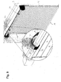
Wie aus Fig. 9 hervorgeht, werden anschließend die aufgewickelten Gurtbänder 42, 44 mittels einer Befestigungseinheit 60 an der Wickelwelle 30 befestigt. Die Befestigungseinheit 60 umfasst ein U-Profil 61 mit an den beiden Stegen des U-Profils angeschlossenen Befestigungsflanschen 62, 63. Jeder der Befestigungsflansche 62, 63 weist zwei Ausnehmungen auf über die die Befestigungseinheit 60 mittels Schrauben oder dergleichen an der Wickelwelle 30 befestigt werden kann. Die Abmessungen der Befestigungseinheit 60 sind dabei derart gewählt, dass die übereinander liegenden Wicklungen des Gurtbandes 42 an die Wickelwelle angedrückt werden. Die das Gurtband 42, 44 an die Wickelwelle 30 anpressende Befestigungseinheit 60, ermöglicht eine wenigstens teilweise, vorzugsweise eine totale Entlastung des Gurtbandes 42, 44 im späteren bestimmungsgemäßen Betrieb des Rolltores 1. Alternativ können auch andere Befestigungsmittel vorgesehen werden, die eine dauerhafte Festlegung des Montagezugmittels 40, 42, 44 an der Wickelwelle 30 gewährleisten.As is apparent from Fig. 9, then the wound webbings 42, 44 are fastened by means of a
Ein weiterer Vorteil der Gurtbänder 42, 44 besteht darin, dass die aufgewickelten Gurtbänder 42, 44 nicht nachträglich entfernt werden müssen, sondern zugleich als dämpfende Auflagerringe während des Aufwickel- oder Abwickelvorganges dienen können. Somit kann die Materialwahl des Montagezugmittels 40 auf diese spätere Dämpfungsfunktion vorab abgestimmt werden. Hierzu kann auch eine entsprechende Anzahl von Gurtbändern als Montagehilfszugmittel gewählt werden.Another advantage of the
Im Folgenden werden anhand der Fig. 10 bis 15 zwei Ausführungsformen einer Verriegelungsvorrichtung 70 zur Ver-/Entriegelung des Rolltorbehanges 10 sowie das Rolltor 1 mit einer solchen Verriegelungsvorrichtung 70 beschrieben. Die in den Querschnitten dargestellte Verriegelungsvorrichtung 70 ist im Bereich beider Seitenränder 14, 15 vorgesehen. So zeigen die Figuren 10 bis 12 jeweils einen Querschnitt durch das oben beschriebene Rolltor 1 mit der Verriegelungsvorrichtung 70 gemäß einer ersten Ausführungsform.In the following, two embodiments of a
Hierbei umfasst die Verriegelungsvorrichtung 70 eine Sperreinheit 80, eine Riegeleinheit 90 und eine Federeinheit 50.Here, the locking
Die Federeinheit 50 weist eine Blattfeder 52 bzw. 54 auf, die mit ihrem ersten Ende 56 über die Befestigungseinheit 60 an der Wickelwelle 30 fixiert ist und mit ihrem zweiten Ende 58 mit der Riegeleinheit 90 verbunden ist. Wie bereits oben erläutert, fixiert die Befestigungseinheit 60 zugleich die Gurtbänder 42, 44 an der Wickelwelle 30.The
Die Sperreinheit umfasst einen Sperrhaken 80 mit einem an der Umrandung 3 festgelegten Befestigungsabschnitt 81 und einem einteilig mit diesem Befestigungsabschnitt 81 verbundenen Hakenabschnitt 82, der in einem vorbestimmten Winkel von dem Befestigungsabschnitt 81 bzw. der Umrandung 3 abragt.The blocking unit comprises a locking hook 80 with a
Die Riegeleinheit 90 ist um eine parallel zur Toröffnung 2 verlaufende horizontale Achse drehbeweglich und dient zugleich als Verbindungselement zwischen dem zweiten Ende 58 der Blattfeder 52 und dem obersten Stab 11 des Rolltorbehanges 10. Wie insbesondere aus Fig. 12 hervorgeht, umfasst die Riegeleinheit 90 mehrere Abschnitte mit einer U-förmigen Nut 92 zum Eingriff mit dem Hakenabschnitt 82, einem Anschlusselement 94 zur drehbeweglichen Verbindung mit dem obersten Stab 11 und einem Drehbolzen 96, der in einer Schlaufe des zweiten Ende 58 der Blattfeder 52 drehbeweglich gelagert ist.The locking
Bei einer Bewegung der Wickelwelle 30 während der Auf- und Abwickelbewegung der Wickelwelle 30 ist die Riegeleinheit infolge der durch die Wickelbewegung veränderten Biegung der Blattfeder 52 von einer Verriegelungsstellung in eine Entriegelungsstellung und umgekehrt verstellbar.During a movement of the winding
Die Verriegelungsvorrichtung 70 befindet sich bei geöffnetem oder nur teilweise geöffneten Rolltor 1, wie in Fig. 10 gezeigt, in der Entriegelungsstellung, in der die Riegeleinheit 90 in einem bestimmten Abstand A von der Umrandung 3 entfernt ist. Dieser Abstand A ergibt sich ohnehin infolge der Führung des Rolltorbehanges 10 in den Führungsschienen 20, 22.The locking
Erst wenn sich der Rolltorbehang 10 nahe oder in der Schließendstellung befindet, wie in Fig. 11 und 12 gezeigt, wird die Riegeleinheit 90 in die Verriegelungsstellung verstellt. In dieser Stellung ragt der oberste Stab 11 wenigstens teilweise aus dem oberen Ende der Führungsschiene 20, 22 hinaus. Infolge der teilweisen Aufwicklung der Blattfeder 52 auf der Wickelwelle 30 und infolge eines Abstandes B zwischen der Drehachse der Wickelwelle 30 und der Umrandung 3 erfährt die Blattfeder 52 in dieser Position eine bestimmte Biegung und übt eine Kraft F1 in Richtung der Umrandung 3 auf die Riegeleinheit 90 und den oberen Endbereich des obersten Stabes 11 aus.Only when the
Infolge dieser Krafteinwirkung wird die zur Umrandung 3 gerichtete Außenseite des obersten Stabes 11 näher in Richtung der Umrandung 3 oder sogar bis an die Umrandung 3 gedrückt, so dass bei einem Einbruchsversuch mit einer Bewegung des Rolltorbehanges 10 nach oben, die Riegeleinheit 90 mit ihrer Nut 92 in Eingriff mit dem Hakenabschnitt 82 gelangt, wodurch eine Bewegung der Riegeleinheit 90 an der Sperreinheit 80 vorbei nicht möglich ist.As a result of this force, the outer edge of the
Bei der zweiten Ausführungsform der Verriegelungsvorrichtung 70 ist als Sperreinheit 85 ein über eine Halterung 87 beabstandet von der Umrandung 3 angeordneter Sperrbolzen 86 vorgesehen. Die zugehörige Riegeleinheit 100 wird durch eine teilweise biegsame Anschlussplatte 100 mit einer Ausnehmung 102 gebildet, wie insbesondere aus Fig. 14 hervorgeht. Diese Anschlussplatte 100 ist drehbeweglich an der Abschlusskante 12 des obersten Stabs 11 angelenkt.In the second embodiment of the
Zur Ver-/Entriegelung der Verriegelungsvorrichtung 70 sind des Weiteren die bereits im Zusammenhang mit der ersten Ausführungsform beschriebene Federeinheit 50 in Form einer Blattfeder 52 sowie ein Sperrelement 110 in Form einer Blattfeder 112 vorgesehen.For locking / unlocking the
Wie Fig. 13 zeigt, fixiert die Befestigungseinheit 60 wiederum sowohl die aufgewickelten Gurtbänder 42, 44 als auch die Blattfeder 52 an der Wickelwelle 30. Die Blattfeder 52 ist mit ihrem zweiten Ende 58 an der Anschlussplatte 100 befestigt.As shown in FIG. 13, the
Der Abschnitt der Blattfeder 52 zwischen der Befestigungseinheit 60 und der Anschlussplatte 100 dient zur Ausübung einer Kraft auf die Anschlussplatte 100, um diese in Richtung der Umrandung 3 zu schwenken und umgekehrt. Diese Kraft wird sowohl durch die lagemäßige Anordnung, den Biegeradius, die Abmessungen als auch durch die Bewegung der Wickelwelle 30 beeinflusst.The portion of the
Die Blattfeder 112 ist mit ihrem ersten Ende 114 über Langlöcher 118 mittels zugehöriger Befestigungsmittel an der Wickelwelle 30 festgelegt. Die Langlöcher 118 können dienen zur genauen Positionierung der Blattfeder 112 an der der Wickelwelle 30, so dass die Blattfeder 112 in einem geeigneten Bereich verschiebbar ist, beispielsweise ohne an die Abschlusskante 12 anzustoßen. Das zweite Ende 116 der Blattfeder 112 ist über eine Führung 105 in den Richtungen G gemäß dem Pfeil in Fig. 13 bewegbar, um die Ausnehmung 102 zu versperren oder freizugeben. Die Führung 105 umfasst zwei L-Profile 106, 107, die an der Anschlussplatte 100 befestigt sind. Die Blattfeder 112 kann wahlweise nur zur Sperrung oder Freigabe der Ausnehmung 102 oder aber zusätzlich zur Ausübung einer Kraft auf die Anschlussplatte 100 in Richtung der Umrandung 3 eingesetzt werden.The
Die in Fig. 13 in einer perspektivischen Ansicht dargestellte Verriegelungsstellung im Bereich der Führungsschiene 22 ist nochmals in Fig. 15 im Querschnitt gezeigt. Die Entriegelungsstellung geht aus Fig. 16 hervor. Wie aus den beiden Figuren 15 und 16 zu entnehmen, befindet sich die Blattfeder 112 in der Verriegelungsstellung in einer Sperrstellung, bei der das zweite Ende 116 die Ausnehmung 102 verdeckt, so dass der Sperrbolzen 85 nicht durch die Ausnehmung 102 gelangen kann. Der Rolltorbehang 10 kann nicht an dem Sperrbolzen 85 vorbei gefahren werden. In Fig. 16 befindet sich das Sperrelement 110 in einer Freigabestellung, bei der das zweite Ende 116 infolge einer Drehung der Wickelwelle 30 der Blattfeder 112 in eine die Ausnehmung 102 freigebende Position überführt ist. Infolge dieser Drehung der Wickelwelle 30 verändert sich die von der Blattfeder 52 ausgeübte Kraft derart, dass die Anschlussplatte 100 derart verschwenkt werden kann, so dass sich die Anschlussplatte 100 nach dem Schwenkvorgang auf der anderen Seite des Sperrbolzens 85 und somit in der Entriegelungsstellung befindet (siehe Fig. 15, 16).The locking position in the region of the
Sowohl die erste als auch die zweite Ausführungsform zeichnet sich dadurch aus, dass die Blattfeder 52 infolge der Bewegung der Wickelwelle 30 zur Verstellung der Riegeleinheit 90 von der Verriegelungsstellung in die Entriegelungsstellung und umgekehrt dient. Weiterhin kann die Befestigungseinheit 60 zur Festlegung und Entlastung des um die Wickelwelle 30 gewickelten Montagezugmittels 40 und zur Befestigung der Blattfeder 52 eingesetzt werden kann. Ein Vorteil der zweiten Ausführungsform besteht darin, dass die Blattfeder 112 einen unberechtigten Öffnungsversuch zuverlässig verhindern kann.Both the first and the second embodiment is characterized in that the
Ferner wird mittels der Gurtbänder 42, 44 als Montagehilfszugmittel eine einfach handhabbare und wenig Arbeitsschritte erfordernde Montage des Rolltorbehanges 10 auf der Wickelwelle 30 ermöglicht. Zudem können die Gurtbänder 42, 44 nach der Montage auf der Wickelwelle 30 verbleiben und dienen als Auflager- und Distanzringe.Further, by means of the
- 11
- Rolltorrolling gate
- 22
- Toröffnungdoor opening
- 33
- Umrandungborder
- 1010
- RolltorbehangDoor curtain
- 1111
- StabRod
- 1212
- Abschlusskanteterminal edge
- 1313
- Schließkanteclosing edge
- 1414
- Seitenrandmargin
- 1515
- Seitenrandmargin
- 1616
- VerpackungseinheitPackaging Unit
- 1717
- Verpackungsteilpackaging part
- 1818
- Fachsubject
- 2020
- Führungsschieneguide rail
- 2222
- Führungsschieneguide rail
- 2424
- Tragkonsolesupport bracket
- 2626
- Tragkonsolesupport bracket
- 2828
- Sturzblendeheader frame
- 3030
- Wickelwellewinding shaft
- 4040
- MontagezugmittelMontagezugmittel
- 4242
- Gurtbandwebbing
- 4444
- Gurtbandwebbing
- 4646
- erstes Endefirst end
- 4848
- zweites Endesecond end
- 5050
- Federeinheitspring unit
- 5252
- Blattfederleaf spring
- 5454
- Blattfederleaf spring
- 5656
- erstes Endefirst end
- 5858
- zweites Endesecond end
- 6060
- Befestigungseinheitfixing unit
- 6161
- U-ProfilU-profile
- 6262
- Flanschflange
- 6363
- Flanschflange
- 6565
- Befestigungselementfastener
- 6666
- Befestigungselementfastener
- 7070
- Verriegelungsvorrichtunglocking device
- 8080
- Sperreinheitblocking unit
- 8181
- Befestigungsabschnittattachment section
- 8282
- Hakenabschnitthook section
- 8585
- Sperreinheitblocking unit
- 8686
- Sperrbolzenlocking pin
- 8787
- Halterungbracket
- 9090
- Riegeleinheitlocking unit
- 9292
- Nutgroove
- 9494
- Anschlusselementconnecting element
- 9696
- Drehbolzenpintle
- 100100
- Anschlussplatteconnecting plate
- 102102
- Ausnehmungrecess
- 105105
- Führungguide
- 106106
- L-ProfilL-profile
- 107107
- L-ProfilL-profile
- 110110
- Sperrelementblocking element
- 112112
- Blattfederleaf spring
- 114114
- erstes Endefirst end
- 116116
- zweites Endesecond end
- 118118
- LanglochLong hole
- AA
- Abstanddistance
- BB
- Abstanddistance
- F1F1
- Kraftforce
- F2F2
- Kraftforce
- GG
- Richtungdirection
Claims (18)
dadurch gekennzeichnet,
dass das Montagezugmittel (40, 42, 44) auf einen axialen Bereich der Wickelwelle (30) aufgewickelt wird, über dem im Betrieb der Rolltorbehang (10) aufgewickelt wird, so dass das aufgewickelte Montagezugmittel (40, 42, 44) im Betrieb des Rolltores (1) als insbesondere dämpfende Zwischenlage zwischen Wickelwelle (30) und Rolltorbehang (10) dient.Method according to claim 1,
characterized,
in that the assembly tension means (40, 42, 44) is wound onto an axial region of the winding shaft (30), over which the roller door curtain (10) is wound during operation, so that the wound assembly tension means (40, 42, 44) during operation of the roller shutter (1) serves as a particular damping intermediate layer between the winding shaft (30) and roller blind curtain (10).
dadurch gekennzeichnet,
dass das aufgewickelte Montagezugmittel (40, 42, 44) im Betrieb des Rolltors eine insbesondere dämpfende Zwischenlage zwischen der Wickelwelle (30) und dem Rolltorbehang bildet.Roller door according to claim 12,
characterized,
that the wound Montagezugmittel (40, 42, 44) in the operation of the rolling shutter forms a particular damping intermediate layer between the winding shaft (30) and the roller blind curtain.
dadurch gekennzeichnet,
dass das Montagezugmittel im aufgewickelten Zustand eine Länge hat, die größer als die Hälfte der aufgewickelten Länge des Rolltorbehanges ist.Roller door according to one of the preceding claims,
characterized,
that the assembly tension means in the wound state has a length which is greater than half of the wound-up length of the roller table hanger.
Applications Claiming Priority (1)
| Application Number | Priority Date | Filing Date | Title |
|---|---|---|---|
| DE200610046008 DE102006046008B3 (en) | 2006-09-28 | 2006-09-28 | Assembly method for roller door and such a roller door |
Publications (3)
| Publication Number | Publication Date |
|---|---|
| EP1908915A2 true EP1908915A2 (en) | 2008-04-09 |
| EP1908915A3 EP1908915A3 (en) | 2010-12-15 |
| EP1908915B1 EP1908915B1 (en) | 2016-11-30 |
Family
ID=38984170
Family Applications (1)
| Application Number | Title | Priority Date | Filing Date |
|---|---|---|---|
| EP07116018.8A Active EP1908915B1 (en) | 2006-09-28 | 2007-09-10 | Assembly method for a rolling gate |
Country Status (2)
| Country | Link |
|---|---|
| EP (1) | EP1908915B1 (en) |
| DE (1) | DE102006046008B3 (en) |
Cited By (1)
| Publication number | Priority date | Publication date | Assignee | Title |
|---|---|---|---|---|
| US12024946B2 (en) | 2020-04-06 | 2024-07-02 | Levolor, Inc. | Shade adapter for a roller shade |
Families Citing this family (3)
| Publication number | Priority date | Publication date | Assignee | Title |
|---|---|---|---|---|
| DE102009019985B4 (en) | 2008-10-22 | 2019-04-18 | A.R.T. Systemtechnik GmbH & Co. KG | System for winding closures for building openings |
| DE202009017783U1 (en) | 2009-05-06 | 2010-08-12 | Palm, Frank | System for winding closures for building openings |
| DE102010031733A1 (en) | 2010-07-21 | 2012-01-26 | Hörmann KG Antriebstechnik | Assembly method and assembly aid for a roll-up door |
Citations (3)
| Publication number | Priority date | Publication date | Assignee | Title |
|---|---|---|---|---|
| EP0238944A2 (en) | 1986-03-27 | 1987-09-30 | HàRmann Kg Bielefeld | Mounting apparatus |
| DE10127015A1 (en) | 2001-01-12 | 2002-07-18 | Hoermann Kg Dissen | Armored rollshutter door assembler uses device to lower shutter shaft and bearings onto supporting arm and into hook type shaft mount releasable by adjuster screw. |
| DE102004003067A1 (en) | 2003-04-03 | 2004-10-14 | Klenk, Gottlieb | Spring device for securing e.g. roller shutters to winding shaft, has main part releasably secured to end section for securing to shutters |
Family Cites Families (5)
| Publication number | Priority date | Publication date | Assignee | Title |
|---|---|---|---|---|
| US4251039A (en) * | 1979-07-30 | 1981-02-17 | Douglas Howard | Rolling door curtain mounting apparatus |
| DE10159419A1 (en) * | 2001-12-04 | 2003-06-12 | Hoermann Kg Verkaufsges | Roller door includes stabilizing components wound up with it when moving between closed and open positions |
| EP1336717A3 (en) * | 2002-02-14 | 2004-03-03 | Hörmann Kg Dissen | Roller door |
| DE20315243U1 (en) * | 2003-10-02 | 2003-12-11 | Warema Renkhoff Gmbh | Installation aid for units such as sunshade systems, roller shutters and doors, for example, has guide device fastened on premounted bracket and over which is guided flexible lifting cable for pulling up unit to height of bracket |
| DE202005007744U1 (en) * | 2005-05-18 | 2005-07-21 | Gollnast System-Anlagen Gmbh | Locking system for roller shutters and doors includes magnet on raised flat extension of stop edge to interact with ferro-magnetic guide element of first shutter bar |
-
2006
- 2006-09-28 DE DE200610046008 patent/DE102006046008B3/en not_active Expired - Fee Related
-
2007
- 2007-09-10 EP EP07116018.8A patent/EP1908915B1/en active Active
Patent Citations (3)
| Publication number | Priority date | Publication date | Assignee | Title |
|---|---|---|---|---|
| EP0238944A2 (en) | 1986-03-27 | 1987-09-30 | HàRmann Kg Bielefeld | Mounting apparatus |
| DE10127015A1 (en) | 2001-01-12 | 2002-07-18 | Hoermann Kg Dissen | Armored rollshutter door assembler uses device to lower shutter shaft and bearings onto supporting arm and into hook type shaft mount releasable by adjuster screw. |
| DE102004003067A1 (en) | 2003-04-03 | 2004-10-14 | Klenk, Gottlieb | Spring device for securing e.g. roller shutters to winding shaft, has main part releasably secured to end section for securing to shutters |
Cited By (1)
| Publication number | Priority date | Publication date | Assignee | Title |
|---|---|---|---|---|
| US12024946B2 (en) | 2020-04-06 | 2024-07-02 | Levolor, Inc. | Shade adapter for a roller shade |
Also Published As
| Publication number | Publication date |
|---|---|
| EP1908915B1 (en) | 2016-11-30 |
| EP1908915A3 (en) | 2010-12-15 |
| DE102006046008B3 (en) | 2008-04-30 |
Similar Documents
| Publication | Publication Date | Title |
|---|---|---|
| DE102007063705B4 (en) | Roller blind with perforated belt drive | |
| EP1970235B1 (en) | Side window blind with wire drive | |
| EP0648913B1 (en) | Security device for a roller shutter formed of slats | |
| DE4104749C2 (en) | Roller shutters | |
| WO2012095324A1 (en) | Folding shutter arrangement having a plurality of inherently rigid folding shutter elements, in particular having element edges that bend out and element edges that do not bend out in alternation | |
| DE69219654T2 (en) | Compensation device for retractable gates with variable speed | |
| WO2011003576A2 (en) | Winding device for covering wall openings or windows | |
| DE3245009A1 (en) | Roller door | |
| EP1908915B1 (en) | Assembly method for a rolling gate | |
| EP2634341A2 (en) | Folding door with two or more inherently rigid folding shutter elements with alternate element edges that do not bend out and element edges that bend out in alternation and operating device for the same | |
| EP2535501B1 (en) | Building shadowing device with extendable guide rails | |
| WO2005082656A1 (en) | Motor vehicle door comprising several adjustable components | |
| EP3695081B1 (en) | Lower door section having a folding roller bracket | |
| EP1366259B1 (en) | Sectional door | |
| EP2565360B1 (en) | Device for securing a roller on a coiling cylinder | |
| DE69822414T2 (en) | Catch device for rollable closure devices | |
| DE19903008C2 (en) | shutters | |
| EP1577485B1 (en) | Roller shutter | |
| DE60000135T2 (en) | Safety device against rolling shutters | |
| EP0383067A1 (en) | Roller shutter for wall or roof openings, especially those with a swinging roof window | |
| DE102005037775A1 (en) | Venetian blind | |
| DE29801334U1 (en) | Roller shutter security | |
| DE102020127200B3 (en) | Roller shutters for closing and / or darkening a building opening and a method for opening a building opening | |
| DE102006046010A1 (en) | Locking device for use in roller shutter, has spring unit staying in effective connection with bolting unit and provided for exertion of force on bolting unit, such that bolting unit is movable from locking position to releasing position | |
| EP1972477A2 (en) | Side window blind with hinged pull bar and rectangular support rod |
Legal Events
| Date | Code | Title | Description |
|---|---|---|---|
| PUAI | Public reference made under article 153(3) epc to a published international application that has entered the european phase |
Free format text: ORIGINAL CODE: 0009012 |
|
| AK | Designated contracting states |
Kind code of ref document: A2 Designated state(s): AT BE BG CH CY CZ DE DK EE ES FI FR GB GR HU IE IS IT LI LT LU LV MC MT NL PL PT RO SE SI SK TR |
|
| AX | Request for extension of the european patent |
Extension state: AL BA HR MK RS |
|
| PUAL | Search report despatched |
Free format text: ORIGINAL CODE: 0009013 |
|
| AK | Designated contracting states |
Kind code of ref document: A3 Designated state(s): AT BE BG CH CY CZ DE DK EE ES FI FR GB GR HU IE IS IT LI LT LU LV MC MT NL PL PT RO SE SI SK TR |
|
| AX | Request for extension of the european patent |
Extension state: AL BA HR MK RS |
|
| 17P | Request for examination filed |
Effective date: 20110610 |
|
| AKX | Designation fees paid |
Designated state(s): AT CH DE LI |
|
| 17Q | First examination report despatched |
Effective date: 20130611 |
|
| GRAP | Despatch of communication of intention to grant a patent |
Free format text: ORIGINAL CODE: EPIDOSNIGR1 |
|
| RIC1 | Information provided on ipc code assigned before grant |
Ipc: E06B 9/80 20060101ALN20160503BHEP Ipc: E06B 9/17 20060101AFI20160503BHEP Ipc: E06B 9/58 20060101ALN20160503BHEP Ipc: E06B 9/86 20060101ALN20160503BHEP Ipc: E06B 9/171 20060101ALN20160503BHEP |
|
| INTG | Intention to grant announced |
Effective date: 20160525 |
|
| GRAS | Grant fee paid |
Free format text: ORIGINAL CODE: EPIDOSNIGR3 |
|
| GRAA | (expected) grant |
Free format text: ORIGINAL CODE: 0009210 |
|
| AK | Designated contracting states |
Kind code of ref document: B1 Designated state(s): AT CH DE LI |
|
| REG | Reference to a national code |
Ref country code: CH Ref legal event code: EP |
|
| REG | Reference to a national code |
Ref country code: CH Ref legal event code: NV Representative=s name: BRAUNPAT BRAUN EDER AG, CH Ref country code: AT Ref legal event code: REF Ref document number: 849983 Country of ref document: AT Kind code of ref document: T Effective date: 20161215 |
|
| REG | Reference to a national code |
Ref country code: DE Ref legal event code: R096 Ref document number: 502007015291 Country of ref document: DE |
|
| REG | Reference to a national code |
Ref country code: DE Ref legal event code: R097 Ref document number: 502007015291 Country of ref document: DE |
|
| PLBE | No opposition filed within time limit |
Free format text: ORIGINAL CODE: 0009261 |
|
| STAA | Information on the status of an ep patent application or granted ep patent |
Free format text: STATUS: NO OPPOSITION FILED WITHIN TIME LIMIT |
|
| 26N | No opposition filed |
Effective date: 20170831 |
|
| REG | Reference to a national code |
Ref country code: CH Ref legal event code: PCAR Free format text: NEW ADDRESS: HOLEESTRASSE 87, 4054 BASEL (CH) |
|
| PGFP | Annual fee paid to national office [announced via postgrant information from national office to epo] |
Ref country code: AT Payment date: 20180918 Year of fee payment: 12 Ref country code: CH Payment date: 20180924 Year of fee payment: 12 |
|
| REG | Reference to a national code |
Ref country code: CH Ref legal event code: PL |
|
| PG25 | Lapsed in a contracting state [announced via postgrant information from national office to epo] |
Ref country code: LI Free format text: LAPSE BECAUSE OF NON-PAYMENT OF DUE FEES Effective date: 20190930 Ref country code: CH Free format text: LAPSE BECAUSE OF NON-PAYMENT OF DUE FEES Effective date: 20190930 |
|
| REG | Reference to a national code |
Ref country code: AT Ref legal event code: MM01 Ref document number: 849983 Country of ref document: AT Kind code of ref document: T Effective date: 20190910 |
|
| PG25 | Lapsed in a contracting state [announced via postgrant information from national office to epo] |
Ref country code: AT Free format text: LAPSE BECAUSE OF NON-PAYMENT OF DUE FEES Effective date: 20190910 |
|
| P01 | Opt-out of the competence of the unified patent court (upc) registered |
Effective date: 20230502 |
|
| REG | Reference to a national code |
Ref country code: DE Ref legal event code: R082 Ref document number: 502007015291 Country of ref document: DE Representative=s name: KASTEL PATENTANWAELTE PARTG MBB, DE |
|
| PGFP | Annual fee paid to national office [announced via postgrant information from national office to epo] |
Ref country code: DE Payment date: 20251118 Year of fee payment: 19 |