EP1908863B1 - Heddle for Jacquard loom - Google Patents
Heddle for Jacquard loom Download PDFInfo
- Publication number
- EP1908863B1 EP1908863B1 EP06021003A EP06021003A EP1908863B1 EP 1908863 B1 EP1908863 B1 EP 1908863B1 EP 06021003 A EP06021003 A EP 06021003A EP 06021003 A EP06021003 A EP 06021003A EP 1908863 B1 EP1908863 B1 EP 1908863B1
- Authority
- EP
- European Patent Office
- Prior art keywords
- heald
- section
- leg
- plastic
- Prior art date
- Legal status (The legal status is an assumption and is not a legal conclusion. Google has not performed a legal analysis and makes no representation as to the accuracy of the status listed.)
- Not-in-force
Links
- 239000004033 plastic Substances 0.000 claims description 49
- 229920003023 plastic Polymers 0.000 claims description 49
- 239000000463 material Substances 0.000 claims description 9
- 230000007704 transition Effects 0.000 claims description 6
- 239000000919 ceramic Substances 0.000 claims description 5
- 239000000853 adhesive Substances 0.000 claims description 3
- 230000001070 adhesive effect Effects 0.000 claims description 3
- 229920001169 thermoplastic Polymers 0.000 claims description 3
- 229920001187 thermosetting polymer Polymers 0.000 claims description 3
- 229920000914 Metallic fiber Polymers 0.000 claims description 2
- 239000004760 aramid Substances 0.000 claims description 2
- 229910052751 metal Inorganic materials 0.000 claims description 2
- 239000002184 metal Substances 0.000 claims description 2
- 102000004169 proteins and genes Human genes 0.000 claims description 2
- 108090000623 proteins and genes Proteins 0.000 claims description 2
- 238000007711 solidification Methods 0.000 claims description 2
- 230000008023 solidification Effects 0.000 claims description 2
- 239000004416 thermosoftening plastic Substances 0.000 claims description 2
- PNEYBMLMFCGWSK-UHFFFAOYSA-N Alumina Chemical compound [O-2].[O-2].[O-2].[Al+3].[Al+3] PNEYBMLMFCGWSK-UHFFFAOYSA-N 0.000 claims 3
- 239000011521 glass Substances 0.000 claims 2
- OKTJSMMVPCPJKN-UHFFFAOYSA-N Carbon Chemical compound [C] OKTJSMMVPCPJKN-UHFFFAOYSA-N 0.000 claims 1
- 229910000831 Steel Inorganic materials 0.000 claims 1
- 229920003235 aromatic polyamide Polymers 0.000 claims 1
- 229910052799 carbon Inorganic materials 0.000 claims 1
- 239000010959 steel Substances 0.000 claims 1
- 210000002414 leg Anatomy 0.000 description 48
- 239000000835 fiber Substances 0.000 description 34
- 239000012783 reinforcing fiber Substances 0.000 description 8
- 238000001746 injection moulding Methods 0.000 description 4
- 238000009941 weaving Methods 0.000 description 4
- 230000001154 acute effect Effects 0.000 description 3
- 229920000049 Carbon (fiber) Polymers 0.000 description 2
- 239000004917 carbon fiber Substances 0.000 description 2
- 239000002131 composite material Substances 0.000 description 2
- 239000003822 epoxy resin Substances 0.000 description 2
- 239000003365 glass fiber Substances 0.000 description 2
- 229920000647 polyepoxide Polymers 0.000 description 2
- 230000002787 reinforcement Effects 0.000 description 2
- TVEXGJYMHHTVKP-UHFFFAOYSA-N 6-oxabicyclo[3.2.1]oct-3-en-7-one Chemical compound C1C2C(=O)OC1C=CC2 TVEXGJYMHHTVKP-UHFFFAOYSA-N 0.000 description 1
- 229920002430 Fibre-reinforced plastic Polymers 0.000 description 1
- 229910000760 Hardened steel Inorganic materials 0.000 description 1
- 229920001872 Spider silk Polymers 0.000 description 1
- 229920006231 aramid fiber Polymers 0.000 description 1
- 239000011195 cermet Substances 0.000 description 1
- 150000001875 compounds Chemical class 0.000 description 1
- 230000006835 compression Effects 0.000 description 1
- 238000007906 compression Methods 0.000 description 1
- 238000011161 development Methods 0.000 description 1
- 230000018109 developmental process Effects 0.000 description 1
- 239000011151 fibre-reinforced plastic Substances 0.000 description 1
- 239000004413 injection moulding compound Substances 0.000 description 1
- 238000003780 insertion Methods 0.000 description 1
- 230000037431 insertion Effects 0.000 description 1
- 239000011159 matrix material Substances 0.000 description 1
- 239000002557 mineral fiber Substances 0.000 description 1
- 238000012986 modification Methods 0.000 description 1
- 230000004048 modification Effects 0.000 description 1
- 239000011224 oxide ceramic Substances 0.000 description 1
- 229910052574 oxide ceramic Inorganic materials 0.000 description 1
- 238000002360 preparation method Methods 0.000 description 1
- 230000005855 radiation Effects 0.000 description 1
- 239000013589 supplement Substances 0.000 description 1
- 230000008719 thickening Effects 0.000 description 1
- 210000000689 upper leg Anatomy 0.000 description 1
Images
Classifications
-
- D—TEXTILES; PAPER
- D03—WEAVING
- D03C—SHEDDING MECHANISMS; PATTERN CARDS OR CHAINS; PUNCHING OF CARDS; DESIGNING PATTERNS
- D03C9/00—Healds; Heald frames
- D03C9/02—Healds
-
- D—TEXTILES; PAPER
- D03—WEAVING
- D03C—SHEDDING MECHANISMS; PATTERN CARDS OR CHAINS; PUNCHING OF CARDS; DESIGNING PATTERNS
- D03C9/00—Healds; Heald frames
- D03C9/02—Healds
- D03C9/024—Eyelets
Definitions
- the invention relates to a heddle, which is particularly suitable for a Jacquard loom.
- Jacquard weaving machine usually use healds, which are suspended resiliently at one end. At the other end of the heald a cord, the so-called harness cord, which leads to a jacquard loom. This exerts on the cords a defined train, whereby the strands can be moved individually and independently.
- This type of Litzenbet decisivist comes at working speeds of modern looms to their limits. In order to keep the strand under control, it is necessary to keep up with growing Speed increasingly stronger springs are used. This burdens the jacquard machines unnecessarily. In addition, the possibility to use stronger springs, set limits due to the limited space.
- the heald known from the cited document has a plastic body into which a lug is inserted to form a thread eye.
- the mandrel is formed by a ring-shaped body made of a material that is harder than the plastic. At its outer periphery, this body has a circumferential, flat groove, in which engages the plastic body.
- the plastic body engages over the edges of the Maillons to secure it form-fitting.
- healds are not directly suitable for jacquard weaving in which the healds between the harness cord and the spring are constantly stretched.
- heald strand body is thickened in the region of the muzzle, which extend straight thigh away from this thickened area.
- the transition from the leg to the thickened thread eye region is formed by a short ramp-like section.
- ie material removal occur when warp threads on the strand along. If fibers of the plastic-fiber composite material are exposed as a result of the wear, then the reinforcing fibers protruding from the plastic body can damage warp threads.
- the disclosed EP 0947620 A1 a heald consisting of a flattened wire-like element.
- this element is provided with a longitudinal slot which is bounded by two legs. The legs are spread apart and hold between each other an eye.
- the strand according to the invention has a strand body consisting of a plastic body in which non-metallic fibers are embedded.
- the thread eye is formed by a Maillon, which consists of a material whose hardness is greater than the hardness of the plastic.
- the Maillon is embedded in the plastic body.
- the peculiarity lies in the strand body made of plastic, which has a ramp section in the transition between the legs and the thread eye portion whose length measured in the leg direction is at least twice as large as the height of the thread opening measured in the same direction.
- long fibers which are preferably oriented in the leg direction and do not extend transversely to the leg or thread eye.
- This type of fiber arrangement is based for example on the embedding of nonwoven fibers, for example so-called rovings in the plastic.
- the fibers then have a preferred orientation to one another, with all the fibers being oriented substantially parallel to one another. Lower deviations from the parallelism arise at most in the area of the ramp section.
- the enclosed by the fibers with each other acute angle is at most as large as the acute angle formed by the ramp section itself.
- the fibers thereof may be arranged to deviate from the circumferential direction of the mail. However, this is limited to an inner region of the plastic body, which is never exposed even with heavy wear and material removal.
- the cross section of the legs is round, with a radius of curvature R1.
- the ramp section and the thread eye section are preferably likewise rounded on their narrow sides. This preferably corresponds to a rounding radius R2 and R3, which corresponds in each case to the rounding radius R1.
- the cross section of the ramp portion and the flattened portion is preferably formed oval, wherein it is bounded by two opposite straight line pieces parallel to each other and two opposing circular arcs. This results in a uniform curvature of the lateral Edges or surfaces which face the warp threads running between the strands.
- the strands are made of a suitable plastic, for example a thermoplastic, but preferably a thermosetting plastic that can be hardened.
- a suitable plastic for example a thermoplastic, but preferably a thermosetting plastic that can be hardened.
- This can be formed, for example, by a two-component plastic, for example an epoxy resin.
- the Maillon is preferably used before the solidification of the plastic in the heald body and thereby connected to this material and form fit. An adhesive is not required to attach the mailbox.
- the strand according to the invention can be produced by injection molding or by injection molding. Preferably, continuous reinforcing fibers are provided which extend from one leg across the mandrel into the other leg.
- the fiber strand used is first soaked with a not yet cured plastic.
- the maillon is used at the desired location.
- the strand is given its final shape by insertion and possibly compression in a mold and is cured, for example by heat or ultraviolet radiation.
- the one end of the strand is preferably shaped so that it can easily be connected to a harness cord.
- the end of the heddle body is formed for example as an eyelet or as a hook. Other forms suitable for connecting a harness cord are possible.
- the second opposite End of the strand body can also be configured, if there is a cord to be connected there. If a pull-down spring is to be connected, the plastic can also be designed so that a hook or a thread is formed, onto which the end of the pull-down spring is to be screwed.
- the ramp section forms a smooth transition between the small cross section of the leg and the larger cross section of the Litzenauges. It can be designed as a straight line piece or S-shaped. Preferably, it is at least 10 mm long. In most preferred embodiments, the length of the ramp section is larger and may be up to 30 mm.
- Developments of the invention are directed to a strand with a Maillon, which forms not only the thread eye, but also, at least parts of the outer surface of the strand.
- the mail may be enlarged to an elongated part, which has the thread eye and additional attachment possibilities for the strand formed from the fibers or the plastic material.
- this enlarged Maillon receives the ramped portions of the strand and, for example, on the narrow sides or on the flat sides arranged longitudinal grooves which receive the relevant part or leg of the plastic body.
- the connection possibilities can be formed by openings through which the fibers of the plastic leg extend.
- Suitable reinforcing fibers are glass fibers, aramid fibers, protein fibers or carbon fibers.
- the fiber reinforcement gives the strands a rigidity which makes it possible to use them in jacquard machines.
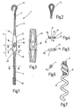
- a stranded wire 1 is illustrated for a Jacquard weaving machine.
- the strand 1 has a strand body 2 with two preferably straight and mutually aligned legs 3, 4, which include a thread eye portion 5 and ramp sections 6, 7 between each other.
- the legs 3, 4 may have the same or different diameters and cross sections. Preferably, they have a round cross-section, as it is for example in Fig. 6 is illustrated by the cross section of the leg 4.
- the leg 4 is substantially cylindrical and its circular cross-section has a radius R1.
- the ends of the legs 3, 4 are adapted for connection to other devices, such as harness cords or tension springs.
- the lower end of the leg 4 may also be formed as a hook or eye. In the preferred case, however, it carries a thread 10, such as in Fig. 7 is indicated, can be screwed to the end of a tension spring 11.
- the thread eye portion 5 includes a mandrel 12, as for example Fig. 3 can be seen.
- the mandrel is formed by an annular body of a hard, wear-resistant material, such as ceramic.
- the ceramic may be a sintered ceramic, a reaction ceramic, an oxide ceramic or the like.
- the mandrel 12 may consist of a cermet, a hard metal, a hardened steel ring or the like. It has a thread guide opening 13, which may be elliptical or oval.
- Fig. 4 illustrates is the Opening 13 of the mail 12 preferably rounded and free of sharp edges. It has, measured in the longitudinal direction of the legs 3, 4 preferably a height which is greater than its width measured transversely thereto.
- the mandrel 12 On its outer circumference, the mandrel 12 defines an all-round channel into which the heddle body 2 engages.
- the thread eye portion 5 has an oval cross-section. This is formed by two mutually parallel edges 14, 15 in the form of straight flat Abschuiften, which are connected at the ends by arcs 16, 17.
- the arcs 16, 17 have a radius of curvature R2, which preferably coincides with the rounding radius R1.
- flanks 18, 19 are there cutouts of a cylinder jacket. In the Fig. 1 visible flanks 18, 19 are oriented parallel to each other.
- the two ramp sections 6, 7 may be the same or as shown differently formed with respect to their length. It is preferably in a range between 10 and 30 mm, while the distance of the flanks 18, 19 from each other is smaller than 10 mm in most cases.
- the ramp sections 6, 7 have a length that is greater, preferably significantly greater, than the height of the thread guide opening 13 to be measured in the same direction.
- the length of the ramp sections 6, 7 is at least twice as long, optimally at least three times as large like the height of the thread opening 13.
- the ramp areas 6, 7 preferably have a constant in Fig. 1 perpendicular to the plane, ie in the direction of the thread guide opening 13, to be measured thickness.
- the ramp sections 6, 7 smoothly connect both to the legs 3, 4 and to the thread guide section 5.
- Fig. 5 illustrates a section of the ramp section 7 at the section line VV.
- the FIGS. 5 and 6 stand on the same scale. It can be seen that the ramp sections 6, 7 have on their flanks 20, 21 a curvature R3 which coincides with the curvature R1 and R2 ( Fig. 4 is drawn on a different scale as the FIGS. 5 and 6 ).
- the body 2 of the strand 1 is a plastic body which, like the Fig. 1-6 suggest reinforcing fibers 22 for reinforcement. These run substantially parallel to a longitudinal direction, which is predetermined by the legs 3, 4 and connects the eyelet 8 with the thread 10.
- the fibers 22 are preferably long fibers, which are all oriented in the longitudinal direction. An exception to the orientation in the longitudinal direction is how Fig. 3 shows, if necessary, in the area of the ramp sections 6, 7 and the thread eye portion 5.
- the reinforcing fibers 22 here circulate the Maillon 12. However, the fibers are oriented here also substantially in the longitudinal direction. In any case, no fiber is arranged transversely.
- the fibers 22 are embedded in the plastic and covered by this.
- the plastic is for example an epoxy resin or another thermosetting plastic. Alternatively, a thermoplastic Plastic used.
- the Maillon 12 is embedded in the plastic body and connected to this materially. The compound is made without additional adhesive by the Maillon is used in the initially uncured plastic, after which the plastic cure
- the fibers 22 may be glass fibers, mineral fibers, carbon fibers or proteinaceous fibers, e.g. be in the form of spider silk.
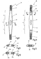
- FIGS. 8 and 9 illustrate a modified and optimized with respect to the use of aggressive warp yarns, such as Armidmaschinen, stranded la.
- This in turn has legs 3, 4, for which the above description applies accordingly.
- the ramp sections 6, 7 are significantly longer than the longitudinal extension of the thread guide opening 13 of the mail 12.
- both the ramp sections 6, 7 and the thread eye section 5 are formed, by enlarging the maillon to an oblong part.
- grooves 23, 24 may be formed through which legs 25, 26 of the plastic body 2 extend.
- the legs 25, 26 connect, as from the FIGS. 8 and 9 shows the legs 3, 4 together and hold the Maillon 12 between each other. They thus constitute a part of the heddle body 2.
- the reinforcing fibers 22 extend from one leg 3 to the other leg 4, passing either through the leg 25 or through the leg 26.
- the legs 25, 26 are substantially embedded in the grooves 23, 24 and thus protected by the hard material of the mail 12 against damage by the abrasive warp threads.
- corresponding grooves 23a, 23b, 24a, 24b according to FIG. 10 provided between which webs 27, 28 project the Maillons 12.
- the webs 27, 28 form formed on the mandrel 12 longitudinally extending ribs that form start-up or contact surfaces for the passing on the strands warp threads.
- the grooves 23a, 23b, 24a, 24b are in turn corresponding portions of the heddle body 2, which hold as Maillon 12 positive and cohesive.
- FIGS. 11 and 12 A further modified embodiment of a stranded wire 1b from the FIGS. 11 and 12 seen.
- the mandrel 12 independently forms the ramp sections 6, 7 and the thread eye section 5.
- the legs 3, 4 are on the Maillon 12 connected. For this purpose, this has recesses with fastening openings 29 at its narrow ends remote from the thread eye 13. In this extension 30 of the leg 3 or 4 may extend into, wherein the plastic including the fibers can enforce the mounting holes 29.
- This strand can be produced in particular by injection molding.
- the mounting holes 29 and recesses provided at the ends of the mailbox serve to anchor the injection molding compound.
- the strand is produced by placing the mailbox in the injection molding machine and then overmolding it.
- the plastic body 2 and the legs 3, 4 may optionally also be made of a plastic, which instead of continuously extending reinforcing fibers short fibers, so-called whiskers.
- whiskers instead of continuously extending reinforcing fibers short fibers
- An inventive strand for Jacquard machines consists essentially of fiber-reinforced plastic, wherein the thread eye is formed by a Maillon 12.
- the heddle body has two legs 3, 4. Between the relatively wide thread eye portion 5 and the legs 3, 4 ramp portions 6, 7 are provided, the length of which is greater than the length of the thread eye 13. Preferably, the length is greater than twice the longitudinal extension of the thread eye. It is in most cases between 10 and 30 mm. By this measure, the wear of the plastic in the vicinity of the thread eye 13 is kept so low that neither damage the stiffening in the plastic body Fibers 22 is still to be feared damage to the warp threads.
Landscapes
- Engineering & Computer Science (AREA)
- Textile Engineering (AREA)
- Looms (AREA)
- Woven Fabrics (AREA)
Description
Die Erfindung betrifft eine Weblitze, die insbesondere für eine Jacquardwebmaschine geeignet ist.The invention relates to a heddle, which is particularly suitable for a Jacquard loom.
Jacquardwebmaschine nutzen in der Regel Weblitzen, die an einem Ende federnd aufgehängt sind. An dem anderen Ende der Weblitze setzt eine Schnur, die so genannte Harnischschnur an, die zu einer Jacquardwebmaschine führt. Diese übt auf die Schnüre einen definierten Zug aus, wodurch die Litzen einzeln und unabhängig voneinander bewegt werden können. Zu den Einzelheiten der Jacquardwebmaschinen wird auf die
Beispielsweise mit der
Solche Weblitzen sind nicht unmittelbar für die Jacquardweberei geeignet, bei denen die Weblitzen zwischen der Harnischschnur und der Feder dauernd gespannt sind.Such healds are not directly suitable for jacquard weaving in which the healds between the harness cord and the spring are constantly stretched.
Des Weiteren wurde mit der
Sowohl bei aus der
Außerdem offenbart die
Durch die Spreizung der Schenkel entsteht an dem Öhr eine Verdickung, die über rampenartige Übergänge an den Litzenkörper angeschlossen ist. Die Länge der Rampe entspricht etwa der Länge des Öhrs.Due to the spreading of the legs creates a thickening on the eye, which is connected via ramp-like transitions to the heald body. The length of the ramp corresponds approximately to the length of the eye.
Davon ausgehend ist es Aufgabe der Erfindung, eine für die Jacquardweberei geeignete verbesserte Litze zu schaffen.On this basis, it is an object of the invention to provide an appropriate for the jacquard weaving improved strand.
Die erfindungsgemäße Litze weist einen Litzenkörper, bestehend aus einem Kunststoffkörper auf, in den nichtmetallische Fasern eingebettet sind. Das Fadenauge wird durch ein Maillon gebildet, das aus einem Material besteht, dessen Härte größer ist als die Härte des Kunststoffs. Das Maillon ist in den Kunststoffkörper eingelassen. Die Besonderheit liegt in dem aus Kunststoff bestehenden Litzenkörper, der im Übergang zwischen den Schenkeln und dem Fadenaugenabschnitt einen Rampenabschnitt aufweist, dessen in Schenkelrichtung gemessene Länge mindestens doppelt so groß ist wie die in gleicher Richtung gemessene Höhe der Fadenöffnung.The strand according to the invention has a strand body consisting of a plastic body in which non-metallic fibers are embedded. The thread eye is formed by a Maillon, which consists of a material whose hardness is greater than the hardness of the plastic. The Maillon is embedded in the plastic body. The peculiarity lies in the strand body made of plastic, which has a ramp section in the transition between the legs and the thread eye portion whose length measured in the leg direction is at least twice as large as the height of the thread opening measured in the same direction.
Mit dieser Maßnahme wird ein besonders flacher Übergang zwischen dem kleinen vorzugsweise runden Querschnitt des Schenkels und dem größeren, abgeflachten Querschnitt des Fadenaugenbereichs erreicht. Kettfäden, die an dem Schenkel, dem Rampenabschnitt und dem Fadenaugenabschnitt entlang streifen, üben somit lediglich einen geringen Druck auf die Kunststoffoberfläche der Litze aus. Der Litzenverschleiß wird dadurch in überschaubaren Grenzen gehalten oder vermieden. Die Gefahr, dass durch den Abtrag der oberen Kunststoffschicht nach und nach Verstärkungsfasern freigelegt werden, die dann die Kettfäden beschädigen können, ist gering, bzw. beseitigt.With this measure, a particularly shallow transition between the small, preferably round cross-section of the leg and the larger, flattened cross-section of the thread eye region is achieved. Warp threads, which run along the leg, the ramp section and the thread eye portion along, thus exert only a small pressure on the plastic surface of the strand. The strand wear is kept within manageable limits or avoided. The risk that by the removal of the upper plastic layer gradually reinforcing fibers are exposed, which can then damage the warp threads, is low, or eliminated.
Es ist möglich, die Fasern als Kurzfasern in den Kunststoff einzubetten, wobei sie dann keine bestimmte Vorzugsorientierung haben müssen. Der flache Anstieg des Rampenabschnitts ermöglicht dies, obwohl sich häufig nur eine sehr geringe Überdeckung der Fasern durch den Kunststoff ergibt.It is possible to embed the fibers as short fibers in the plastic, in which case they have no particular preferred orientation need to have. The flat rise of the ramp section allows this, although often results in only a very small coverage of the fibers through the plastic.
Es wird als vorteilhaft angesehen, lange Fasern zu verwenden, die vorzugsweise in Schenkelrichtung orientiert sind und nicht quer zum Schenkel bzw. Fadenauge verlaufen. Diese Art der Faseranordnung beruht beispielsweise auf der Einbettung von nicht gewebten Fasern, beispielsweise so genannten Rovings in den Kunststoff. Die Fasern haben dann eine Vorzugsorientierung zueinander, wobei alle Fasern im Wesentlichen parallel zueinander orientiert sind. Geringere Abweichungen von der Parallelität ergeben sich allenfalls im Bereich des Rampenabschnitts. Der von den Fasern untereinander eingeschlossene spitze Winkel ist dabei höchstens so groß wie der von dem Rampenabschnitt selbst gebildete spitze Winkel. Unmittelbar an dem Maillon können die die Fasern davon abweichend der Umfangsrichtung des Maillons folgend angeordnet sein. Dies beschränkt sich aber auf einen inneren Bereich des Kunststoffkörpers, der auch bei starkem Verschleiß und Materialabtrag nie freigelegt wird.It is considered advantageous to use long fibers, which are preferably oriented in the leg direction and do not extend transversely to the leg or thread eye. This type of fiber arrangement is based for example on the embedding of nonwoven fibers, for example so-called rovings in the plastic. The fibers then have a preferred orientation to one another, with all the fibers being oriented substantially parallel to one another. Lower deviations from the parallelism arise at most in the area of the ramp section. The enclosed by the fibers with each other acute angle is at most as large as the acute angle formed by the ramp section itself. Immediately adjacent to the mandrel, the fibers thereof may be arranged to deviate from the circumferential direction of the mail. However, this is limited to an inner region of the plastic body, which is never exposed even with heavy wear and material removal.
Vorzugsweise ist der Querschnitt der Schenkel rund, mit einem Rundungsradius R1. Der Rampenabschnitt und der Fadenaugenabschnitt sind an ihren Schmalseiten vorzugsweise ebenfalls gerundet. Dies vorzugsweise mit einem Rundungsradius R2 und R3 der jeweils mit dem Rundungsradius R1 übereinstimmt. Der Querschnitt des Rampenabschnitts und des abgeflachten Bereichs ist vorzugsweise oval ausgebildet, wobei er von zwei einander gegenüberliegenden zueinander parallelen Geradenstücken und zwei einander gegenüberliegenden Kreisbögen begrenzt ist. Dies ergibt eine einheitliche Krümmung der seitlichen Kanten bzw. Flächen, die den zwischen den Litzen laufenden Kettfäden zugewandt sind.Preferably, the cross section of the legs is round, with a radius of curvature R1. The ramp section and the thread eye section are preferably likewise rounded on their narrow sides. This preferably corresponds to a rounding radius R2 and R3, which corresponds in each case to the rounding radius R1. The cross section of the ramp portion and the flattened portion is preferably formed oval, wherein it is bounded by two opposite straight line pieces parallel to each other and two opposing circular arcs. This results in a uniform curvature of the lateral Edges or surfaces which face the warp threads running between the strands.
Die Litzen sind aus einem geeigneten Kunststoff, beispielsweise einem thermoplastischen Kunststoff, vorzugsweise aber einem aushärtbaren duroplastischen Kunststoff ausgebildet. Dieser kann beispielsweise durch einen Zweikomponentenkunststoff, beispielsweise ein Epoxidharz, gebildet sein. Es sind durch Wärme aushärtbare Zweikomponenten-Kunststoffe, durch Ultraviolettstrahlen aushärtbare Kunststoffe oder auch chemisch aktivierbare Zweikomponentenkunststoffe verwendbar. Das Maillon wird vorzugsweise vor dem Erstarren des Kunststoffs in den Litzenkörper eingesetzt und dadurch mit diesem stoff- und formschlüssig verbunden. Ein Klebstoff ist zur Befestigung des Maillons nicht erforderlich. Die erfindungsgemäße Litze kann im Spritzgießverfahren oder im Spritzpressverfahren hergestellt werden. Vorzugsweise werden durchgehend verlaufende Verstärkungsfasern vorgesehen, die sich von einem Schenkel über das Maillon hinweg in den anderen Schenkel hinein erstrecken. Zur Herstellung wird der verwendete Faserstrang zunächst mit einem noch nicht ausgehärteten Kunststoff getränkt. In diesem Faserstrang wird das Maillon an der gewünschten Stelle eingesetzt. Die Litze erhält ihre endgültige Form durch Einlegen und gegebenenfalls Verpressen in einer Form und wird beispielsweise durch Wärme oder Ultraviolettstrahlung ausgehärtet.The strands are made of a suitable plastic, for example a thermoplastic, but preferably a thermosetting plastic that can be hardened. This can be formed, for example, by a two-component plastic, for example an epoxy resin. There are heat curable two-component plastics, ultraviolet curable plastics or chemically activated two-component plastics usable. The Maillon is preferably used before the solidification of the plastic in the heald body and thereby connected to this material and form fit. An adhesive is not required to attach the mailbox. The strand according to the invention can be produced by injection molding or by injection molding. Preferably, continuous reinforcing fibers are provided which extend from one leg across the mandrel into the other leg. For the preparation of the fiber strand used is first soaked with a not yet cured plastic. In this fiber strand, the maillon is used at the desired location. The strand is given its final shape by insertion and possibly compression in a mold and is cured, for example by heat or ultraviolet radiation.
Das eine Ende der Litze wird vorzugsweise so geformt, dass es einfach mit einer Harnischschnur verbunden werden kann. Dazu wird das Ende des Litzenkörpers beispielsweise als Öse oder als Haken ausgebildet. Andere zum Anschluss einer Harnischschnur geeignete Formen sind möglich. Das zweite gegenüberliegende Ende des Litzenkörpers kann ebenso ausgestaltet werden, wenn auch dort eine Schnur angeschlossen werden soll. Wenn eine Niederzugfeder anzuschließen ist, kann der Kunststoff auch so ausgebildet sein, dass ein Haken oder ein Gewinde entsteht, auf welches das Ende der Niederzugfeder aufzuschrauben ist.The one end of the strand is preferably shaped so that it can easily be connected to a harness cord. For this purpose, the end of the heddle body is formed for example as an eyelet or as a hook. Other forms suitable for connecting a harness cord are possible. The second opposite End of the strand body can also be configured, if there is a cord to be connected there. If a pull-down spring is to be connected, the plastic can also be designed so that a hook or a thread is formed, onto which the end of the pull-down spring is to be screwed.
Der Rampenabschnitt bildet einen sanften Übergang zwischen dem kleinen Querschnitt des Schenkels und dem größerem Querschnitt des Litzenauges. Er kann als Geradenstück oder S-förmig ausgebildet sein. Vorzugsweise ist er mindestens 10 mm lang. Bei am meisten bevorzugten Ausführungsformen ist die Länge des Rampenabschnitts größer und kann bis zu 30 mm betragen.The ramp section forms a smooth transition between the small cross section of the leg and the larger cross section of the Litzenauges. It can be designed as a straight line piece or S-shaped. Preferably, it is at least 10 mm long. In most preferred embodiments, the length of the ramp section is larger and may be up to 30 mm.
Weiterbildungen der Erfindung richten sich auf eine Litze mit einem Maillon, das nicht nur das Fadenauge, sondern auch, zumindest Teile der Außenfläche der Litze, bildet. Beispielsweise kann das Maillon zum einem länglichen Teil vergrößert ausgebildet sein, das das Fadenauge und zusätzliche Befestigungsmöglichkeiten für den aus den Fasern gebildeten Strang bzw. das Kunststoffmaterial aufweist. In einer bevorzugten Ausführung erhält dieses vergrößerte Maillon die rampenförmigen Bereiche der Litze und z.B. an den Schmalseiten oder an den Flachseiten angeordnete Längsnute, die den betreffenden Teil oder Schenkel des Kunststoffkörpers aufnehmen. Außerdem ist es möglich, das Maillon als Mittelstück des Litzenkörpers mit Anschlussmöglichkeiten für die beiden Schenkel auszubilden. Die Anschlussmöglichkeiten können durch Öffnungen gebildet sein, durch die sich die Fasern des aus Kunststoff bestehenden Schenkels erstrecken.Developments of the invention are directed to a strand with a Maillon, which forms not only the thread eye, but also, at least parts of the outer surface of the strand. For example, the mail may be enlarged to an elongated part, which has the thread eye and additional attachment possibilities for the strand formed from the fibers or the plastic material. In a preferred embodiment of this enlarged Maillon receives the ramped portions of the strand and, for example, on the narrow sides or on the flat sides arranged longitudinal grooves which receive the relevant part or leg of the plastic body. In addition, it is possible to form the Maillon as a center piece of the strand body with connection options for the two legs. The connection possibilities can be formed by openings through which the fibers of the plastic leg extend.
Als Verstärkungsfasern eignen sich Glasfasern, Aramidfasern, Eiweißfasern oder Karbonfasern. Durch die Faserverstärkung erhalten die Litzen eine Steifigkeit die den Einsatz in Jacquardmaschinen möglich macht.Suitable reinforcing fibers are glass fibers, aramid fibers, protein fibers or carbon fibers. The fiber reinforcement gives the strands a rigidity which makes it possible to use them in jacquard machines.
Weitere Einzelheiten vorteilhafter Ausführungsformen der Erfindung sind Gegenstand der Zeichnung, der Beschreibung oder von Ansprüchen. Nachfolgend sind Ausführungsbeispiele der Erfindung erläutert. Die Beschreibung beschränkt sich auf die Erläuterung wesentlicher Aspekte der Erfindung und sonstiger Gegebenheiten, wobei Abwandlungen möglich sind. Kleinere, nicht beschriebene Details kann der Fachmann in der gewohnten Weise den Zeichnungen entnehmen, die insoweit die Figurenbeschreibung ergänzen. Die nachfolgenden Zeichnungen sind nicht maßstäblich. Zur Veranschaulichung der wesentlichen Details kann es sein, dass bestimmte Bereiche übertrieben groß dargestellt sind. Es zeigen:
- Fig. 1
- eine erfindungsgemäße Litze in vereinfachter Seitenansicht,
- Fig. 2
- eine abgewandelte Ausführungsform des Endes der Litze nach
Fig.1 , - Fig. 3
- den Fadenaugenbereich der Litze nach
Fig.1 in vergrößerter Darstellung, - Fig. 4
- den Fadenaugenbereich der Litze nach
Fig.1 in Schnittdarstellung, geschnitten entlang der Linie IV-IV inFig.1 , - Fig. 5
- den Rampenabschnitt der Litze nach
Fig.1 in Schnittdarstellung, geschnitten entlang der Linie V-V inFig.1 , - Fig. 6
- den Schenkel der Litze nach
Fig.1 , geschnitten entlang der Linie VI-VI inFig.1 , - Fig. 7
- ein Ende eines Schenkels der Litze nach
Fig.1 in Verbindung mit einer angeschlossenen Feder, - Fig. 8
- eine abgewandelte Ausführungsform der erfindungsgemäßen Litze in ausschnittsweiser Seitenansicht,
- Fig. 9
- die Litze nach
Fig.8 , geschnitten am Fadenauge entlang der Linie IX-IX, - Fig. 10
- eine abgewandelte Ausführungsform der Weblitze nach
Fig.8 , geschnitten am Fadenauge entlang der Linie IX-IX, - Fig. 11
- eine weitere Ausführungsform der erfindungsgemäßen Litze in ausschnittsweiser Seitenansicht und
- Fig. 12
- die Litze nach
Fig.11 , geschnitten an der Linie XII-XII.
- Fig. 1
- a strand according to the invention in a simplified side view,
- Fig. 2
- a modified embodiment of the end of the strand after
Fig.1 . - Fig. 3
- the thread eye area of the strand after
Fig.1 in an enlarged view, - Fig. 4
- the thread eye area of the strand after
Fig.1 in section, cut along the line IV-IV inFig.1 . - Fig. 5
- the ramp section of the strand after
Fig.1 in section, cut along the line VV inFig.1 . - Fig. 6
- follow the leg of the strand
Fig.1 , cut along the line VI-VI inFig.1 . - Fig. 7
- one end of a leg of the strand following
Fig.1 in conjunction with a connected spring, - Fig. 8
- a modified embodiment of the strand according to the invention in a sectional side view,
- Fig. 9
- the strand after
Figure 8 cut on the thread eye along the line IX-IX, - Fig. 10
- a modified embodiment of the heald after
Figure 8 cut on the thread eye along the line IX-IX, - Fig. 11
- a further embodiment of the strand according to the invention in a sectional side view and
- Fig. 12
- the strand after
fig.11 , cut on the line XII-XII.
In
Die Enden der Schenkel 3, 4 sind zur Verbindung mit weiteren Einrichtungen, wie beispielsweise Harnischschnüren oder zugfedern, eingerichtet. Beispielsweise endet das obere Ende des Schenkels 3 in einem Haken 8. Alternativ kann es in einer beispielsweise aus
Der Fadenaugenabschnitt 5 enthält ein Maillon 12, wie es beispielsweise
An seinem Außenumfang definiert das Maillon 12 eine ringsum laufende Rinne, in die der Litzenkörper 2 greift. Der Fadenaugenabschnitt 5 weist einen ovalen Querschnitt auf. Dieser wird durch zwei, parallel zueinander orientierte Kanten 14, 15 in Form von geraden flachen Abschuiften gebildet, die endseitig durch Kreisbögen 16, 17 verbunden sind. Die Kreisbögen 16, 17 weisen einen Rundungsradius R2 auf, der vorzugsweise mit dem Rundungsradius R1 übereinstimmt.On its outer circumference, the
Die Kanten 16, 17 folgen jeweils einem Kreisbogen. Sie ergeben side im Querschnitt der seitlichen Flanken 18,19 Fadenangebereides 5 bei der Schnittlinie IV-IV. Die Flanken 18, 19 sind dort Ausschnitte eines Zylindermantels. Die in
Die beiden Rampenabschnitte 6, 7 können gleich oder wie dargestellt hinsichtlich ihrer Länge unterschiedlich ausgebildet sein. Sie liegt vorzugsweise in einem Bereich zwischen 10 und 30 mm, während der Abstand der Flanken 18, 19 voneinander in den meisten Fällen kleiner als 10 mm ist. Die Rampenabschnitte 6, 7, weisen eine Länge auf, die größer, vorzugsweise deutlich größer ist als die in gleicher Richtung zu messenden Höhe der Fadenführungsöffnung 13. Die Länge der Rampenabschnitte 6, 7 ist jeweils mindestens doppelt so groß, optimalerweise mindestens drei mal so groß wie die Höhe der Fadenöffnung 13.The two
Die Rampenbereiche 6, 7 weisen vorzugsweise eine konstante in
Der Körper 2 der Litze 1 ist ein Kunststoffkörper, der, wie die
Die Fasern 22 können Glasfasern, Mineralfasern, Carbonfasern oder auch Eiweißfasern z.B. in Form von Spinnenseide sein.The
Durch den geringen spitzen Winkel zwischen den Flanken 21, 20 von vorzugsweise weniger als 20 Grad wird sichergestellt, dass die auftretende Abnutzung der Kunststoffschicht an den Flanken 18, 19, 20, 21 relativ gering bleibt und die vorhandenen Fäden auch nach Abtragen der Kunststoffschicht kaum freigelegt werden. Durch die Längsorientierung aller Fasern wird erreicht, dass auch dann, wenn ein Teil der deckenden Kunststoffschicht abgetragen wird, die Fasern 22 intakt bleiben und die Zugfestigkeit der Litze 1 weiterhin sicherstellen. Außerdem wird durch den bewussten Verzicht auf jegliche quer laufende Fasern sichergestellt, dass die an den womöglich freigelegten Fasern entlanglaufenden Kettfäden nicht beschädigt werden.Due to the small acute angle between the
Die Schenkel 25, 26 verbinden, wie aus den
Bei einer abgewandelten Ausführungsform sind entsprechende Nuten 23a, 23b, 24a, 24b gemäß
Eine weiter abgewandelte Ausführungsform einer Litze 1b aus den
Für diese und für die anderen Ausführungsformen gilt, dass der Kunststoffkörper 2 bzw. die Schenkel 3, 4 gegebenenfalls auch aus einem Kunststoff hergestellt werden kann, der anstelle durchgehend verlaufender Verstärkungsfasern Kurzfasern, sogenannte Whiskers aufweist. Das Ergebnis bezüglich der Belastbarkeit der Litze ist dann etwas geringer, wobei es für manche Anwendungsfälle ausreichend ist.For this and for the other embodiments applies that the
Eine erfindungsgemäße Litze für Jacquardmaschinen besteht im Wesentlichen aus faserverstärktem Kunststoff, wobei das Fadenauge durch ein Maillon 12 gebildet wird. Der Litzenkörper weist zwei Schenkel 3, 4 auf. Zwischen dem relativ breiten Fadenaugenbereich 5 und den Schenkeln 3, 4 sind Rampenabschnitte 6, 7 vorgesehen, deren Länge größer als die Länge des Fadenauges 13 ist. Vorzugsweise ist die Länge größer als die doppelte Längserstreckung des Fadenauges. Sie liegt in den meisten Fällen zwischen 10 und 30 mm. Durch diese Maßnahme wird der Verschleiß des Kunststoffs in Nachbarschaft des Fadenauges 13 so gering gehalten, dass weder eine Beschädigung der im Kunststoffkörper aussteifenden Fasern 22 noch eine Beschädigung der Kettfäden zu befürchten ist.An inventive strand for Jacquard machines consists essentially of fiber-reinforced plastic, wherein the thread eye is formed by a
- 11
- Litze, 1a, 1bLitz, 1a, 1b
- 22
- Litzenkörperheald
- 33
- Schenkelleg
- 44
- Schenkelleg
- 55
- FadenaugenabschnittThread eye section
- 66
- Rampenabschnittramp section
- 77
- Rampenabschnittramp section
- 88th
- Hakenhook
- 99
- Öseeyelet
- 1010
- Gewindethread
- 1111
- Zugfedermainspring
- 1212
- MaillonMaillon
- 1313
- FadenführungsöffnungThread guide opening
- 1414
- Kanteedge
- 1515
- Kanteedge
- 1616
- Kreisbogenarc
- 1717
- Kreisbogenarc
- 1818
- Flankeflank
- 1919
- Flankeflank
- 2020
- Flankeflank
- 2121
- Flankeflank
- 2222
- Fasernfibers
- 2323
- Nut, 23a, 23bGroove, 23a, 23b
- 2424
- Nut, 24a, 24bGroove, 24a, 24b
- 2525
- Schenkelleg
- 2626
- Schenkelleg
- 2727
- Stegweb
- 2828
- Stegweb
- 2929
- Befestigungsöffnungfastening opening
- 3030
- Fortsatzextension
Claims (19)
- Heald (1, 1a, 1b) for a Jacquard loom,
with a heald body (2), and a mail (12), which has a thread opening (13) and is embedded into the heald body (2),
wherein the heald body (2):• has legs (3, 4) that have a round cross-section and extend away from the mail (12)• has a flattened cross-section on a thread eye section (5) surrounding the mail (12), and• in the transition area from the thread eye section (5) to the leg (3, 4) has a ramp section (6, 7), the cross-section of which is flattened and increases from the leg (3, 4) towards the thread eye section (5),characterised in that the length of the ramp sections (6, 7) measured in the longitudinal direction of the leg is respectively at least double the size of the height of the thread opening (13) measured in the same direction, that the heald body is made of plastic, into which non-metallic fibres (22) are embedded, and that the mail is made of a material with a hardness greater than the hardness of the plastic. - Heald according to claim 1, characterised in that the cross-section of the leg (3, 4) has a radius of curvature (R1), and that the cross-section of the flattened region has a radius of curvature (R2).
- Heald according to claim 2, characterised in that the radius of curvature (R1) of the leg is the same as the radius of curvature (R2 or R3) of the ramp section (6, 7) or the thread eye section (5).
- Heald according to claim 1, characterised in that the cross-section of the ramp section (6, 7) or the thread eye section (5) is oval in configuration such that it is defined by two opposing, straight, mutually parallel linear pieces (14, 15) and two circular arcs (16, 17) located opposite one another.
- Heald according to claim 1, characterised in that the plastic is a curable thermosetting plastic.
- Heald according to claim 1, characterised in that the plastic is a thermoplastic.
- Heald according to claim 5 or 6, characterised in that the mail (12) is inserted into the heald body (2) before solidification of the plastic and is secured without adhesive.
- Heald according to claim 1, characterised in that the fibres (22) are long fibres, which are oriented solely along the heald body (2).
- Heald according to claim 1, characterised in that fibres (22) are short fibres.
- Heald according to claim 9, characterised in that the fibres (22) are arranged randomly in the heald body (2).
- Heald according to claim 1, characterised in that the mail (12) has at least one section, which forms the ramp section (6, 7).
- Heald according to claim 1, characterised in that the heald body (2) extends through at least one groove (23), which is configured on the mail (12).
- Heald according to claim 12, characterised in that the groove (25) of the mail (12) receives the respective leg (25) of the heald body (2).
- Heald according to claim 13, characterised in that the leg (25) of the heald body (2) is enclosed by the groove (23) of the mail (12).
- Heald according to claim 1, characterised in that the mail (12) is made of glass, aluminium oxide, ceramic, hard metal or highly hardenable steel.
- Heald according to claim 1, characterised in that the fibres are glass, aramid, carbon fibres or protein-based fibres.
- Heald according to claim 1, characterised in that the heald body (2) is interrupted on the mail (12) and the legs (3, 4) are fastened to the mail (12).
- Heald according to claim 17, characterised in that the mail respectively has at least one fastening opening (29) for connection of a leg (3, 4).
- Jacquard harness with a heald according to one of the preceding claims.
Priority Applications (4)
| Application Number | Priority Date | Filing Date | Title |
|---|---|---|---|
| EP06021003A EP1908863B1 (en) | 2006-10-06 | 2006-10-06 | Heddle for Jacquard loom |
| BRPI0703652-3A BRPI0703652A (en) | 2006-10-06 | 2007-10-03 | Jacquard Weaving Machine |
| CN2007101622721A CN101158077B (en) | 2006-10-06 | 2007-10-08 | Heddle for jacquard loom |
| US11/907,034 US7464730B2 (en) | 2006-10-06 | 2007-10-09 | Weaving heddle for jacquard weaving machine |
Applications Claiming Priority (1)
| Application Number | Priority Date | Filing Date | Title |
|---|---|---|---|
| EP06021003A EP1908863B1 (en) | 2006-10-06 | 2006-10-06 | Heddle for Jacquard loom |
Publications (2)
| Publication Number | Publication Date |
|---|---|
| EP1908863A1 EP1908863A1 (en) | 2008-04-09 |
| EP1908863B1 true EP1908863B1 (en) | 2009-04-08 |
Family
ID=37496966
Family Applications (1)
| Application Number | Title | Priority Date | Filing Date |
|---|---|---|---|
| EP06021003A Not-in-force EP1908863B1 (en) | 2006-10-06 | 2006-10-06 | Heddle for Jacquard loom |
Country Status (4)
| Country | Link |
|---|---|
| US (1) | US7464730B2 (en) |
| EP (1) | EP1908863B1 (en) |
| CN (1) | CN101158077B (en) |
| BR (1) | BRPI0703652A (en) |
Cited By (2)
| Publication number | Priority date | Publication date | Assignee | Title |
|---|---|---|---|---|
| CN103849973A (en) * | 2014-03-19 | 2014-06-11 | 常州市武进牛塘如意纺织器材厂 | Special flat steel heald for weaving carbon fiber |
| EP3839115B1 (en) * | 2019-12-20 | 2022-09-07 | Staubli Lyon | Heddle for weaving loom and harness provided with such a heddle |
Families Citing this family (17)
| Publication number | Priority date | Publication date | Assignee | Title |
|---|---|---|---|---|
| EP2019157B1 (en) * | 2007-07-26 | 2010-06-30 | Groz-Beckert KG | Narrow cropped heald |
| EP2166138A1 (en) * | 2008-09-23 | 2010-03-24 | Groz-Beckert KG | Jacquard heald with embossed heald eye area |
| BE1018304A3 (en) * | 2008-10-13 | 2010-08-03 | Wiele Michel Van De Nv | HEVEL. |
| DE102009010316B4 (en) * | 2009-02-24 | 2016-11-10 | Karl Mayer Textilmaschinenfabrik Gmbh | Method for producing a knitting tool holder |
| BE1018732A3 (en) * | 2009-04-24 | 2011-07-05 | Wiele Michel Van De Nv | THREE-DIMENSIONAL LEVEL. |
| EP2505703B1 (en) * | 2011-03-28 | 2014-12-03 | Groz-Beckert KG | Plastic heald and method for producing same from a sheet of film |
| EP2505701B1 (en) * | 2011-03-28 | 2014-12-31 | Groz-Beckert KG | Multiple component plastic heddle and method for its manufacture |
| CN102776648A (en) * | 2012-07-25 | 2012-11-14 | 浙江旷达纺织机械有限公司 | Harness cord steel disc heald rod for weaving machine |
| US9328435B2 (en) * | 2013-11-08 | 2016-05-03 | Deertex, Inc. | Functional weaving vamp fabric |
| CN103668638A (en) * | 2013-11-29 | 2014-03-26 | 湖州金能达印染有限公司 | Improved multifunctional heddle |
| FR3027313B1 (en) * | 2014-10-16 | 2016-11-18 | Staubli Lyon | SMOOTH FOR WEAVING WEAVING, WOVEN WEAVING EQUIPPED WITH SUCH A SMOOTH, AND METHOD FOR MANUFACTURING SUCH A SMOOTH |
| FR3027314B1 (en) * | 2014-10-16 | 2019-04-26 | Staubli Lyon | SMOOTH FOR WEAVING AND WEAVING EQUIPMENT EQUIPPED WITH SUCH A SMOOTH |
| FR3027315B1 (en) * | 2014-10-16 | 2019-04-26 | Staubli Lyon | SMOOTH FOR WEAVING AND WORK EQUIPPED WITH SUCH A SMOOTH |
| TWM493278U (en) * | 2014-10-21 | 2015-01-11 | Deertex Inc | Footwear assembly with breathable and wear-resistant woven vamp |
| JP7560407B2 (en) | 2021-05-07 | 2024-10-02 | 津田駒工業株式会社 | Held |
| FR3146149B1 (en) | 2023-02-28 | 2025-03-07 | Staubli Lyon | Heddle for a loom and loom equipped with such a heddle |
| FR3155244B1 (en) * | 2023-11-09 | 2025-11-14 | Staubli Lyon | Jacquard heddle and loom including such a Jacquard heddle |
Family Cites Families (30)
| Publication number | Priority date | Publication date | Assignee | Title |
|---|---|---|---|---|
| BE342071A (en) * | ||||
| US887102A (en) * | 1907-09-24 | 1908-05-12 | William Shinn Lackey | Heddle. |
| US997283A (en) * | 1908-07-11 | 1911-07-11 | Steel Heddle Mfg Co | Heddle. |
| US1413949A (en) * | 1921-09-08 | 1922-04-25 | Paul A Wagner | Heddle for looms |
| US1648139A (en) * | 1925-10-28 | 1927-11-08 | Rene A Machon | Heddle for jacquard weaving |
| US1944516A (en) * | 1930-10-25 | 1934-01-23 | Atlanta Harness And Reed Mfg C | Loom harness and mail eye therefor |
| US1930151A (en) * | 1931-11-04 | 1933-10-10 | Rhode Island Warp Stop Equipme | Heddle or drop-wire |
| US2019822A (en) * | 1934-07-24 | 1935-11-05 | Steel Heddle Mfg Co | Loom heddle and method of making the same |
| US2249390A (en) * | 1939-02-26 | 1941-07-15 | Mahler Otto | Heddle |
| US3049151A (en) * | 1960-06-01 | 1962-08-14 | Greensboro Loom Reed Company I | Anti-friction instrumentalities for a loom |
| US3960182A (en) * | 1975-04-07 | 1976-06-01 | Staeubli, Ltd. | Heddles for weaving machines having heddle frame bars for several heddles, which bars are moved by a shed-forming device |
| CH631755A5 (en) | 1978-09-26 | 1982-08-31 | Braecker Ag | FABRIC. |
| US4355665A (en) * | 1980-05-26 | 1982-10-26 | Bracker Ag | Heddle |
| US4790357A (en) * | 1987-08-06 | 1988-12-13 | Steel Heddle Mfg., Inc. | Harness frame slat and heddle |
| IT1228325B (en) * | 1989-01-09 | 1991-06-11 | Vamatex Spa | TEXTURE FRAMEWORK FOR ASYMMETRIC CONFIGURATION. |
| US5052446A (en) | 1989-06-12 | 1991-10-01 | Sulzer Brothers Limited | Thermoplastic heddle with braided fiber tube reinforcement |
| US5092370A (en) * | 1990-01-31 | 1992-03-03 | Asten Group, Inc. | Split heddle with superimposed blades with aligned apertures |
| DE4023498C1 (en) * | 1990-07-24 | 1991-10-24 | Grob & Co Ag, Horgen, Zuerich, Ch | |
| US5348055A (en) * | 1993-05-06 | 1994-09-20 | Steel Heddle Mfg. Co. | Heddle eyelet structure |
| DE4336362C1 (en) * | 1993-10-25 | 1994-10-13 | Grob & Co Ag | Thread eyelet for a heald |
| CH692587A5 (en) * | 1997-09-16 | 2002-08-15 | Braecker Ag | Rod-shaped thread-guiding element for textile machines, in particular heddle, and methods for producing the same. |
| DE19800811B4 (en) * | 1998-01-12 | 2009-06-04 | Grob Textile Ag | heald |
| FR2776676B1 (en) * | 1998-03-31 | 2000-05-26 | Staubli Lyon | METHOD FOR MANUFACTURING A SMOOTH, SMOOTH AND CROWD FORMING DEVICE FOR WEAVING MATERIAL |
| DE19932685A1 (en) * | 1999-07-13 | 2001-01-18 | Grob Horgen Ag Horgen | Loom harness heald has upper and lower eyelets to fit around heald carrier rails of different cross sections with a structured play to reduce wear and prevent loom shaft distortion |
| CH695240A5 (en) * | 2001-02-28 | 2006-02-15 | Braecker Ag | Heddle and method for producing a heddle. |
| DE10116813B4 (en) * | 2001-04-04 | 2010-04-01 | Grob Textile Ag | Webschafteckverbindung |
| DE10124022C2 (en) * | 2001-05-17 | 2003-04-10 | Inst Textil & Faserforschung | Shed forming device with spring damping |
| FR2835538B1 (en) * | 2002-02-07 | 2004-05-21 | Staubli Lyon | HEADBED AND METHOD FOR MANUFACTURING IT, DEVICE FOR FORMING THE HEAD AND LOMING INCORPORATING SUCH HEADBED |
| DE10206130B4 (en) * | 2002-02-14 | 2016-09-01 | Groz-Beckert Kg | Weave with at least one heald |
| DE10325908B4 (en) * | 2003-06-05 | 2005-07-21 | Groz-Beckert Kg | Shaft rod, heald frame and method for producing a shaft rod |
-
2006
- 2006-10-06 EP EP06021003A patent/EP1908863B1/en not_active Not-in-force
-
2007
- 2007-10-03 BR BRPI0703652-3A patent/BRPI0703652A/en not_active Application Discontinuation
- 2007-10-08 CN CN2007101622721A patent/CN101158077B/en active Active
- 2007-10-09 US US11/907,034 patent/US7464730B2/en active Active
Cited By (2)
| Publication number | Priority date | Publication date | Assignee | Title |
|---|---|---|---|---|
| CN103849973A (en) * | 2014-03-19 | 2014-06-11 | 常州市武进牛塘如意纺织器材厂 | Special flat steel heald for weaving carbon fiber |
| EP3839115B1 (en) * | 2019-12-20 | 2022-09-07 | Staubli Lyon | Heddle for weaving loom and harness provided with such a heddle |
Also Published As
| Publication number | Publication date |
|---|---|
| EP1908863A1 (en) | 2008-04-09 |
| CN101158077B (en) | 2011-09-14 |
| CN101158077A (en) | 2008-04-09 |
| BRPI0703652A (en) | 2008-06-03 |
| US20080083471A1 (en) | 2008-04-10 |
| US7464730B2 (en) | 2008-12-16 |
Similar Documents
| Publication | Publication Date | Title |
|---|---|---|
| EP1908863B1 (en) | Heddle for Jacquard loom | |
| EP2162634B1 (en) | Arrangement for connecting an elongate element to a further component | |
| EP2475817B1 (en) | Rope comprising carbon filaments | |
| EP2166139B1 (en) | Jacquard braiding with embossed fibre eye area | |
| EP2659039A2 (en) | Seat-belt strap for a seat-belt system | |
| DE102010011792A1 (en) | cable end | |
| DE102016210040A1 (en) | A method for producing an at least partially profiled, fiber-reinforced plastic profile, a profiled, fiber-reinforced plastic profile and its use | |
| EP1739215B1 (en) | Thread protecting heddle | |
| EP1795636B1 (en) | Heald for warp yarns having a band shape | |
| EP2198085B1 (en) | Transporting belt with peripheral reinforcement | |
| EP2505701B1 (en) | Multiple component plastic heddle and method for its manufacture | |
| DE3004075A1 (en) | ELASTIC JOINT, CLUTCH OR THE LIKE | |
| DE102017223577B3 (en) | Rack for rapier looms | |
| EP1560959B1 (en) | Top comb and top comb holder for a textile combing machine | |
| EP1743966B1 (en) | Weaving heald, in particular for high speed weaving machines | |
| EP3400131A1 (en) | Fiber composite component, structural component, and production method | |
| DE69913301T2 (en) | Pair of weft grippers for weaving machines | |
| EP1643157B1 (en) | Toothed belt | |
| DE3148086A1 (en) | EDGE PROTECTING DEVICE AND LINKED BELT WITH IT | |
| EP1586683B1 (en) | Gripper tape for a rapier loom and rapier loom | |
| EP0564954B1 (en) | Chain link plate and method of manufacturing the same | |
| CH706587A1 (en) | Clothing support. | |
| DE202024102779U1 (en) | Snow sliding board with one or more functional layers | |
| DE202024102780U1 (en) | Snow sliding board with one or more functional layers | |
| DE102011002796A1 (en) | Carrier element for receiving in a train or Lastträgergurt |
Legal Events
| Date | Code | Title | Description |
|---|---|---|---|
| PUAI | Public reference made under article 153(3) epc to a published international application that has entered the european phase |
Free format text: ORIGINAL CODE: 0009012 |
|
| AK | Designated contracting states |
Kind code of ref document: A1 Designated state(s): AT BE BG CH CY CZ DE DK EE ES FI FR GB GR HU IE IS IT LI LT LU LV MC NL PL PT RO SE SI SK TR |
|
| AX | Request for extension of the european patent |
Extension state: AL BA HR MK RS |
|
| 17P | Request for examination filed |
Effective date: 20080419 |
|
| GRAP | Despatch of communication of intention to grant a patent |
Free format text: ORIGINAL CODE: EPIDOSNIGR1 |
|
| GRAS | Grant fee paid |
Free format text: ORIGINAL CODE: EPIDOSNIGR3 |
|
| AKX | Designation fees paid |
Designated state(s): BE CZ FR IT |
|
| REG | Reference to a national code |
Ref country code: DE Ref legal event code: 8566 |
|
| GRAA | (expected) grant |
Free format text: ORIGINAL CODE: 0009210 |
|
| AK | Designated contracting states |
Kind code of ref document: B1 Designated state(s): BE CZ FR IT |
|
| PLBE | No opposition filed within time limit |
Free format text: ORIGINAL CODE: 0009261 |
|
| STAA | Information on the status of an ep patent application or granted ep patent |
Free format text: STATUS: NO OPPOSITION FILED WITHIN TIME LIMIT |
|
| 26N | No opposition filed |
Effective date: 20100111 |
|
| PGFP | Annual fee paid to national office [announced via postgrant information from national office to epo] |
Ref country code: CZ Payment date: 20141001 Year of fee payment: 9 Ref country code: FR Payment date: 20141022 Year of fee payment: 9 |
|
| PG25 | Lapsed in a contracting state [announced via postgrant information from national office to epo] |
Ref country code: CZ Free format text: LAPSE BECAUSE OF NON-PAYMENT OF DUE FEES Effective date: 20151006 |
|
| REG | Reference to a national code |
Ref country code: FR Ref legal event code: ST Effective date: 20160630 |
|
| PG25 | Lapsed in a contracting state [announced via postgrant information from national office to epo] |
Ref country code: FR Free format text: LAPSE BECAUSE OF NON-PAYMENT OF DUE FEES Effective date: 20151102 |
|
| PGFP | Annual fee paid to national office [announced via postgrant information from national office to epo] |
Ref country code: BE Payment date: 20200916 Year of fee payment: 15 |
|
| PGFP | Annual fee paid to national office [announced via postgrant information from national office to epo] |
Ref country code: IT Payment date: 20200911 Year of fee payment: 15 |
|
| REG | Reference to a national code |
Ref country code: BE Ref legal event code: MM Effective date: 20211031 |
|
| PG25 | Lapsed in a contracting state [announced via postgrant information from national office to epo] |
Ref country code: BE Free format text: LAPSE BECAUSE OF NON-PAYMENT OF DUE FEES Effective date: 20211031 |
|
| PG25 | Lapsed in a contracting state [announced via postgrant information from national office to epo] |
Ref country code: IT Free format text: LAPSE BECAUSE OF NON-PAYMENT OF DUE FEES Effective date: 20211006 |