EP1908634B1 - Motoranordnung - Google Patents
Motoranordnung Download PDFInfo
- Publication number
- EP1908634B1 EP1908634B1 EP07117702A EP07117702A EP1908634B1 EP 1908634 B1 EP1908634 B1 EP 1908634B1 EP 07117702 A EP07117702 A EP 07117702A EP 07117702 A EP07117702 A EP 07117702A EP 1908634 B1 EP1908634 B1 EP 1908634B1
- Authority
- EP
- European Patent Office
- Prior art keywords
- motor
- circuit board
- pair
- motor assembly
- plug
- Prior art date
- Legal status (The legal status is an assumption and is not a legal conclusion. Google has not performed a legal analysis and makes no representation as to the accuracy of the status listed.)
- Active
Links
Images


Classifications
-
- H—ELECTRICITY
- H02—GENERATION; CONVERSION OR DISTRIBUTION OF ELECTRIC POWER
- H02K—DYNAMO-ELECTRIC MACHINES
- H02K5/00—Casings; Enclosures; Supports
-
- B—PERFORMING OPERATIONS; TRANSPORTING
- B60—VEHICLES IN GENERAL
- B60R—VEHICLES, VEHICLE FITTINGS, OR VEHICLE PARTS, NOT OTHERWISE PROVIDED FOR
- B60R1/00—Optical viewing arrangements; Real-time viewing arrangements for drivers or passengers using optical image capturing systems, e.g. cameras or video systems specially adapted for use in or on vehicles
- B60R1/02—Rear-view mirror arrangements
- B60R1/06—Rear-view mirror arrangements mounted on vehicle exterior
- B60R1/062—Rear-view mirror arrangements mounted on vehicle exterior with remote control for adjusting position
- B60R1/07—Rear-view mirror arrangements mounted on vehicle exterior with remote control for adjusting position by electrically powered actuators
-
- B—PERFORMING OPERATIONS; TRANSPORTING
- B60—VEHICLES IN GENERAL
- B60R—VEHICLES, VEHICLE FITTINGS, OR VEHICLE PARTS, NOT OTHERWISE PROVIDED FOR
- B60R1/00—Optical viewing arrangements; Real-time viewing arrangements for drivers or passengers using optical image capturing systems, e.g. cameras or video systems specially adapted for use in or on vehicles
- B60R1/02—Rear-view mirror arrangements
- B60R1/06—Rear-view mirror arrangements mounted on vehicle exterior
- B60R1/0605—Rear-view mirror arrangements mounted on vehicle exterior specially adapted for mounting on trucks, e.g. by C-shaped support means
- B60R1/0607—Rear-view mirror arrangements mounted on vehicle exterior specially adapted for mounting on trucks, e.g. by C-shaped support means with remote position control adjustment
- B60R1/0612—Rear-view mirror arrangements mounted on vehicle exterior specially adapted for mounting on trucks, e.g. by C-shaped support means with remote position control adjustment by electrically actuated means
-
- B—PERFORMING OPERATIONS; TRANSPORTING
- B60—VEHICLES IN GENERAL
- B60R—VEHICLES, VEHICLE FITTINGS, OR VEHICLE PARTS, NOT OTHERWISE PROVIDED FOR
- B60R1/00—Optical viewing arrangements; Real-time viewing arrangements for drivers or passengers using optical image capturing systems, e.g. cameras or video systems specially adapted for use in or on vehicles
- B60R1/02—Rear-view mirror arrangements
- B60R1/06—Rear-view mirror arrangements mounted on vehicle exterior
- B60R1/062—Rear-view mirror arrangements mounted on vehicle exterior with remote control for adjusting position
- B60R1/07—Rear-view mirror arrangements mounted on vehicle exterior with remote control for adjusting position by electrically powered actuators
- B60R1/074—Rear-view mirror arrangements mounted on vehicle exterior with remote control for adjusting position by electrically powered actuators for retracting the mirror arrangements to a non-use position alongside the vehicle
Definitions
- the present invention relates to a motor assembly used in an outer mirror driving apparatus to turn an outer mirror for a vehicle between a position in which the outer mirror is in a position to be used and a position in which the outer mirror is in a position not to be used.
- An outer mirror driving apparatus to drive an outer mirror between a position in which the outer mirror is in a position to be used and a position in which the outer mirror is in a position not to be used has been known.
- a disk-shaped mirror joining portion configured to be turned within a predetermined angle range is provided on a top portion of the outer mirror driving apparatus.
- a disk-shaped base portion is joined on a lower portion of the outer mirror of a vehicle and the base portion is fixed to the mirror joining portion with bolts.
- the outer mirror driving apparatus is configured to turn the mirror joining portion so that the outer mirror is turned between a position in which the outer mirror is in a position to be used and a position in which the outer mirror is in a position not to be used.
- the outer mirror driving apparatus has a mirror turning shaft, a power transmission mechanism, and a motor assembly.
- the mirror joining portion is joined together on an upper end portion of the mirror turning shaft, and the power transmission mechanism having gears, or the like is configured to transmit power from the motor assembly to the mirror turning shaft.
- the motor assembly has a motor as a power source, a circuit board on which a control circuit to control the motor is mounted, and a supporting member to fix the motor, the circuit board, and the like.
- Harnesses to feed power to the motor are connected to the circuit board, and extend outwardly to an outside of the outer mirror driving apparatus.
- a pair of threaded holes are provided on a chassis wall of the motor, in which a driving shaft is projected, so that the motor can be threadably fixed with the pair of screws.
- Electrodes of the motor and the circuit board are connected to each other with a pair of lead wires fixed by soldering.
- a motor fixing portion and a board supporting portion are formed together on the supporting member, and a driving shaft hole in which the driving shaft of the motor is inserted is provided.
- a pair of threaded holes are provided on both sides of the driving shaft hole.
- a pair of notched portions are provided on the board supporting portion at an interval corresponding to a width of the circuit board and are configured to be engaged with both corners of one end of the circuit board so that the circuit board is supported.
- Screws are inserted in the pair of threaded holes provided on the motor fixing portion in a state where the driving shaft of the motor is inserted in the driving shaft hole, and screwed in threaded holes of the motor to fix the motor.
- the pair of corners of the circuit board are engaged with the pair of notched portions.
- the circuit board is fixed on the board supporting portion in a state where the circuit board is disposed at an interval in relation to the motor.
- a gear or the like is fixed to the motor and the assembled motor assembly is installed in the outer mirror driving apparatus.
- the circuit board is engaged to be fixed with board locking portions provided in an inside of a case of the outer mirror driving apparatus.
- the motor and the circuit board are required to be preliminarily connected to each other with lead wires, and screws are needed to fix the motor. Consequently a connecting process to connect the motor to the circuit board, a fixing process to fix the motor with screws, and the like are required so that production efficiency is decreased due to an increased number of assembling processes.
- the circuit board since only one end of the circuit board is engaged to allow the circuit board to be supported on the supporting member and the circuit board is connected to the motor with the lead wires, the circuit board is fixed to the motor in an unstable state.
- the circuit board is also moved so that there is a risk that the circuit board is detached from the board locking portions, the notched portions, or the like.
- DE-40/9787 shows a conventional system that has a plug and socket connection.
- An object of the present invention is to provide a motor assembly which can be easily assembled, and in which a motor and a circuit board can be fixed easily and stably without fixing members or the like.
- a motor assembly includes a motor provided with a socket unit, a circuit board on which a control circuit to control the motor and a plug unit are mounted, and a supporting member which supports the motor and the circuit board.
- the supporting member has a board supporting portion which supports the circuit board and a motor fixing portion which supports the motor and a supporting member engagement portion.
- the plug unit has a plug unit engagement portion which is engaged with the supporting member engagement portion. The plug unit engagement portion is engaged with the supporting member engagement portion when the plug unit is fitted to the socket unit.
- the supporting member engagement portion is formed by a pair of plug stop projections which are provided together with the motor supporting portion and configured to stop the plug unit in an engaged state from both sides of the plug unit in a width direction of the circuit board.
- FIG.1 is a perspective view showing an outer mirror driving apparatus in which a motor assembly according to an embodiment of the present invention is installed and an outer mirror which is configured to be turned by the outer mirror driving apparatus.
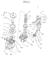
- FIG.2 is an exploded perspective view showing an outer mirror driving apparatus in which a motor assembly according to an embodiment of the present invention is used.
- FIG.3 is a perspective view showing a motor assembly according to an embodiment of the present invention.
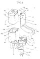
- FIG.4 is an exploded perspective view showing a motor assembly according to an embodiment of the present invention.
- FIG.5 is a front view showing a surface of a circuit board used in a motor assembly according to an embodiment of the present invention, on which electrode terminals are provided.
- FIG.6 is a perspective view showing a surface of a circuit board used in a motor assembly according to an embodiment of the present invention, on which electrode terminals are provided.
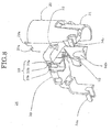
- FIG.7 is a perspective view showing a supporting member used in a motor assembly according to an embodiment of the present invention.
- FIG.8 is a perspective view showing a supporting member used in a motor assembly according to an embodiment of the present invention, viewed from a direction of an arrow A shown in FIG.7 .
- FIG.9 is a front view showing a supporting member forming a motor assembly according to an embodiment of the present invention, viewed from a direction of an arrow B shown in FIG.7 .
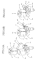
- FIG.10A is a view illustrating an assembling method of a motor assembly according to an embodiment of the present invention.
- FIG.10B is a view illustrating an assembling method of a motor assembly according to an embodiment of the present invention.
- FIG.10C is a view illustrating an assembling method of a motor assembly according to an embodiment of the present invention.
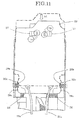
- FIG.11 is a section view along A-A line shown in FIG.3 illustrating an engaged state of a circuit board.
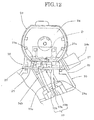
- FIG.12 is a view showing an upper surface of a motor assembly according to an embodiment of the present invention viewed from a direction of an arrow C shown in FIG.10C .
- FIG. 13 is an enlarged view of D part shown in FIG. 12 .
- FIG.14 is a perspective view illustrating a harness holding portion, viewed from a direction of an arrow E shown in FIG.10C .
- a motor assembly according to an embodiment of the present invention may be used in, for example, an outer mirror driving apparatus for a vehicle.
- FIG.1 shows an outer mirror driving apparatus 5 using a motor assembly according to an embodiment of the present invention, an outer mirror 1 for a vehicle, an assistant mirror 2, a stay portion 3, and a joining base portion 4.
- a disk-shaped mirror joining portion 6a is provided on a top portion of the outer mirror driving apparatus 5.
- the outer mirror 1 for a vehicle and the assistant mirror 2 are mounted on a top portion of the substantially L-shaped stay portion 3.
- the disk-shaped joining base portion 4 is joined on a lower portion of the stay portion 3.
- the joining base portion 4 is fixed on the mirror joining portion 6a of the outer mirror driving apparatus 5 with bolts.
- the outer mirror driving apparatus 5 is configured to turn the mirror joining portion 6a such that the outer mirror 1 for a vehicle is turned between a position in which the outer mirror is in a position to be used and a position in which the outer mirror is in a position not to be used.
- FIG.2 shows a configuration of the outer mirror driving apparatus 5 having the motor assembly 7 according to an embodiment of the present invention as a power source.
- the outer mirror driving apparatus 5 also has a mirror turning shaft 6, a power transmission mechanism to transmit the power from the motor assembly 7 to the mirror turning shaft 6, and cases 8A, 8B to contain the above components.
- the mirror turning shaft 6 has the mirror joining portion 6a and a shaft portion 6b, and the mirror joining portion 6a is joined on a top end of the shaft portion 6b.
- the power transmission mechanism is formed of a gear, a spring, or the like, and is configured to transmit the power from the motor assembly 7 to the mirror turning shaft 6 so that the mirror turning shaft 6 is turned.
- the shaft portion 6b of the mirror turning shaft 6 is inserted in a gland 9, a plate 10, and a bush 11 in order, and passes through a shaft hole 8Aa provided on the upper case 8A.
- a pair of ball supporting portions 8Ab, 8Ab are provided on both sides of the shaft hole 8Aa of the case 8A.
- a bearing ball 12 is disposed rotatably on each of the ball supporting portions 8Ab, 8Ab and the bearing balls 12, 12 are placed between the plate 10 and the case 8A.
- a stopper member 13, which interferes with the plate 10 to limit a turning angle of the plate 10, is provided on a top portion of the case 8A.
- the shaft portion 6b is inserted in a washer 14, a spring 15, a clutch gear 16, and a clutch holder 17, and is provided with an F shaped ring 18. Consequently, the mirror turning shaft 6 is disposed rotatably in the shaft hole 8Aa of the case 8A.
- a shaft hole 8Ba which receives a lower end portion of the mirror turning shaft 6, a motor assembly receiving portion 19 which receives the motor assembly 7, and a worm gear receiving portion 20 are provided on the lower case 8B.
- a worm gear 21 is fitted in the worm gear receiving gear 20.
- the worm gear 21 has a shaft 21a, and a helical gear 23 is provided on the shaft 21a.
- a concave portion is formed on each of the ends of the shaft 21a, and a ball 22 is disposed to abut each of the concave portions.
- the motor assembly 7 has a motor 24 as a power source.
- a driving shaft 24a of the motor 24 is provided with a worm gear 36 via a joint 35.
- the motor assembly 7 is mounted on the motor assembly receiving portion 19, and the upper case 8A and the lower case 8B are fixed to each other with screws.
- a turning force of the motor 24 is transmitted to the helical gear 23 via the worm gear 36.
- the turning force is then transmitted to the clutch gear 16 via the worm gear 21 to form a turning force to turn the mirror turning shaft 6.
- the motor assembly 7 includes the motor 24 provided with a socket unit, a circuit board 25 on which a control circuit to control the motor 24 and a plug unit are mounted, and a supporting member 26 which supports the motor 24 and the circuit board 25.
- the motor 24 has the driving shaft 24a, a case portion 24b, and a cap portion 24c.
- a pair of electrode socket portions 24d, 24d as the socket unit are provided on the cap portion 24c.
- a pair of electrode terminals 27, 27 as the plug unit are provided, for example, to stand in a thickness direction of the circuit board on one surface of the circuit board 25. Harnesses such as lead wires 25a, 25a are mounted on the other surface of the circuit board 25.
- the pair of electrode terminals 27, 27 of the circuit board 25 are inserted and fitted, for example, in the thickness direction of the circuit board to the pair of the electrode socket portions 24d, 24d of the motor 24, respectively.
- a plurality of electronic parts such as the control circuit, and the like are mounted on the circuit board 25.
- the circuit board 25 is formed in, for example, a substantially rectangle shape as viewed in a plan view as a whole.
- the circuit board 25 has an end side in a longitudinal direction, on which the pair of electrode terminals 27, 27 are disposed and arranged in parallel to each other in a width direction of the circuit board 25.
- a notched portion 28 is formed on each of the corners of the other end side in the longitudinal direction of the circuit board 25.
- Each of the notched portions 28 is made by cutting out the circuit board 25 itself, that is to say, is formed by an engagement tab 28a which is placed far from the opposite end in which the pair of electrode terminals 27, 27 are provided and a notched concave portion 28b which is placed near the opposite end of the circuit board 25 so as to abut the engagement tab 28a.
- Each of the engagement tabs 28a is projected outwardly in the width direction of the circuit board 25, and each of the notched concave portion 28b is notched inwardly in the width direction of the circuit board 25.
- FIG.6 shows an example of a structure of the electrode terminals 27, 27.
- Each of the electrode terminals 27, 27 has a plug unit engagement portion which is configured to be engaged with a supporting member engagement portion (described below).
- the plug unit engagement portion has a crank portion 27A and a curved base portion 27B.
- the crank portion 27A has a plug portion 27Aa, a stopped portion 27Ab, and a stand portion 27Ac.
- the stopped portion 27Ab is formed at a middle of the crank portion 27A so that the electrode terminal 27 is formed in a crank shape at large.
- the stopped portion 27Ab is formed to extend parallel to the circuit board 25 from an end of the plug portion 27Aa.
- the stand portion 27Ac is formed to extend vertically to the circuit board 25 from an end of the stopped portion 27Ab to be connected to a top portion of the curved base portion 27B.
- Each of the curved base portions 27B is provided with a pair of terminal portions 27Ba, 27Ba. Each of the terminal portions 27Ba is inserted in a fitting hole provided on the circuit board 25 to be joined on the circuit board 25.
- Each of the plug portions 27Aa extends parallel to the thickness direction of the circuit board 25 and is configured to be fitted in each of the electrode socket portions 24d.
- FIGs. 7 to 9 show the supporting member 26.
- the supporting member 26 according to an embodiment of the present invention has a board supporting portion to support the circuit board, a motor supporting portion to support the motor, and the above-mentioned supporting member engagement portion which is engaged with the plug unit engagement portion of the plug unit.
- the supporting member 26 may be formed by a motor insertion portion 29 as the motor supporting portion, base portion 30 as the board supporting portion, and a worm gear insertion portion 31.
- the supporting member 26 having slight flexibility is made of a resin product produced by being molded in an integral molding state.
- the motor 24 is capable of being inserted in a drive axis direction of the motor into the motor insertion portion 29.
- the circuit board 25 is capable of being fitted on the base portion 30 to be supported.
- the motor insertion portion 29 is formed, for example, in a tubular shape, and the supporting member engagement portion is provided on an end of an insertion opening 29b of the tubular motor insertion portion 29.
- the supporting member engagement portion is formed by a pair of plug stop projections 29a, 29a provided so as to extend in an opposite direction to the inserting direction of the motor 24.
- the plug unit engagement portion is engaged with the supporting member engagement portion when the plug unit is fitted in the socket unit.
- the plug stop projections 29a, 29a stop the stand portions 27Ac, 27Ac of the electrode terminals 27, 27 in an engaged state by clipping the stand portions 27Ac, 27Ac from both sides of the electrode terminals in the width direction of the circuit board 25.
- the stopped portions 27Ab, 27Ab are stopped in an engaged state by the plug stop projections 29a, 29a, respectively, so that the electrode terminals are prevented from being withdrawn from the motor 24.
- a stop wall 29c is provided on an inside end of the tubular motor insertion portion 29 corresponding to a front end of the motor 24 in the inserting direction of the motor 24.
- a shaft hole 29d in which the driving shaft 24a of the motor 24 is inserted is provided on the stop wall 29c.
- An abutting ring 29e is provided on a circumference of the shaft hole 29d.
- the base portion 30 of the supporting member 26 is provided with slit portions 32, 32, a harness holding portion 33, and a worm gear bearing portion 34a.
- the worm gear insertion portion 31 is also provided with worm gear bearing portions 34b, 34c.
- each of the worm gear bearing portions 34a, 34b, 34c is formed in a semi-cylindrical shape, and extends downwardly from the base portion 30 to support, from above, the shaft 21a of the worm gear 21, which is a part of the power transmission mechanism.
- the pair of slit portions 32, 32 are placed at an interval to each other, and the interval corresponds to a width of the circuit board 25.
- Each of the slit portions 32 is formed by guide slits 32a, 32a, a space 32b, and a latch portion 32c.
- the pair of slit portions 32, 32 are engaged with a front end portion of the circuit board 25 in an inserting direction of the circuit board 25 from both sides of the circuit board 25.
- each of the notched portions 28 (see FIG.5 ) of the circuit board 25 is guided to pass between the pair of guide slits 32a, 32a. Then, each of the engagement tabs 28a passes over the corresponding latch portions 32c so that the latch portions 32c are fitted in the notched concave portions 28b, as shown in FIG.11 . Thereby, the circuit board 25 is prevented from being withdrawn in an opposite direction to the inserting direction of the motor 24.
- the harness holding portion 33 is formed at an opposite side from the motor insertion portion 29 across the slit portions 32, 32.
- the harness holding portion 33 has a harness protecting space 33a and a pair of harness guiding tabs 33b, 33b .
- the harness protecting space 33a is configured to receive the lead wires 25a, 25a connected to the circuit board 25, and the pair of harness guiding tabs 33b, 33b guide the lead wires 25a, 25a to the harness protecting space 33a and retain the harnesses in the harness protecting space 33a to prevent the harnesses from being withdrawn.
- the harness protecting space 33a extends in the inserting direction of the motor 24, and the pair of harness guiding tabs 33b, 33b extend from a pair of side walls forming the harness protecting space 33a so that a small space is formed between the harness guiding tabs 33b, 33b.
- the lead wires 25a, 25a are guided through the small space to the harness protecting space 33a, and then stopped with the harness guiding tabs 33b, 33b. Consequently, even when the lead wires 25a, 25a are moved, the movement of the lead wires 25a, 25a is inhibited so that the movement is not transmitted to a joining portion between the circuit board 25 and the lead wires 25a, 25a.
- FIG.10 shows an example of an assembling method of the motor assembly according to an embodiment of the present invention.
- the electrode terminals 27, 27 of the circuit board 25 are fitted in the electrode socket portions 24d, 24d (see FIG.4 ) of the motor 24, respectively, as shown by arrow A1 in FIG.10 .
- the circuit board 25 and the motor 24 are disposed parallel to each other and are connected to each other via a space therebetween.
- the motor 24 is inserted in the motor insertion portion 29 until the motor 24 is stopped by the abutting ring 29e.
- each of the latch portions 32c recovers in an initial state to be engaged with the corresponding notched concave portion 28b of the notched portion 28.
- each of the stand portions 27Ac of the pair of electrode terminals 27, 27 is inserted between the pair of the plug stop projections 29a, 29a of the motor insertion portion 29.
- the stopped portions 27Ab, 27Ab of the pair of the electrode terminals 27, 27 are disposed between the pair of plug stop projections 29a, 29a and the motor 24 and then the plug unit is prevented from being withdrawn from the motor 24.
- circuit board 25 and the motor 24 are disposed at an interval, connected to each other, and fixed together to the supporting member 26.
- the lead wires 25a, 25a are inserted between the harness guiding tabs 33b, 33b of the harness holding portion 33 to be disposed along the harness protecting space 33a (see arrow A3 in FIG.10C ) so that the assembling of the motor assembly 7 is completed.
- the circuit board 25 is engaged with the slit portions 32, 32 in a state in which the circuit board 25 and the motor 24 are engaged with each other via the pair of electrode terminals 27, 27 to be connected to each other, the circuit board 25 is prevented from being withdrawn in the inserting direction of the motor 24 (see the direction of arrow A4 in FIG.11 ) so that the motor is prevented from being withdrawn from the motor insertion portion 29 via the circuit board 25.
- the motor 24 is fixed on the motor insertion portion 29 only by a fit of the electrode terminals 27, 27 to the electrode socket portions 24d, 24d and an engagement of the circuit board 25 with the slit portions 32, 32, the motor can be easily fixed on the supporting member 26 without any fixing members such as screws or the like so that the production cost can be prevented from increasing.
- the pair of electrode terminals 27, 27 are stopped in a engaged state with the pair of plug stop projections 29a, 29a by being clipped from both sides in the inserting direction of the motor 24.
- the circuit board 25 can be prevented from moving in a direction in which the plug stop projections 29a, 29a extend (see the direction of arrows A5, A6 in FIG.13 ).
- the motor 24 can be prevented from inversely rotating about the driving shaft 24a due to a reactive force of torque with the rotation of the driving shaft 24a of the motor 24.
- the electrode terminals 27, 27 can be prevented from being withdrawn from the motor 24 in the thickness direction of the circuit board 25 (see arrow A7 in FIG.13 ) so that power distribution to the motor 24 can be steadily performed.
- the circuit board 25 Since the electrode terminals 27, 27 are fixed on the circuit board 25, the circuit board 25 is not withdrawn from the motor 24.
- the circuit board 25 and the motor 24 can be steadily fixed together to the supporting member 26 by cooperation of a fixation of the circuit board 25 to the motor 24 by the plug stop projections 29a, 29a, and an engagement of the circuit board 25 with the supporting member 26 by the slit portions 32, 32.
- the motor 24 and the circuit board 25 are mounted on the supporting member 26 only by the fit and the engagement of the plug unit and the like, the assembling of the motor assembly can be easily performed without fixing members such as screws or the like so that the production cost can be prevented from increasing.
- the supporting member 26 is provided with the harness holding portion 33 having the harness protecting space 33a configured to receive the lead wires 25a, 25a extending from the circuit board 25 and the harness guiding tabs 33b, 33b configured to stop in an engaged state the lead wires 25a, 25a, even when the lead wires 25a, 25a are moved, the lead wires 25a, 25a are stopped in an engaged state so that a force is not transmitted to the joint portion of the lead wires 25a, 25a and the circuit board 25. Therefore, the lead wires 25a, 25a and the circuit board 25 at the joint portion thereof can be protected.
- the lead wires 25a, 25a are stopped in an engaged state in the harness guiding tabs 33b, 33b, the lead wires 25a, 25a are prevented from being inserted in the cases 8A, 8B, so that a length of the lead wires withdrawn outside the cases 8A, 8B can be made stable.
- the electrode terminals 27, 27 have the same structure, since the single electrode terminal 27 can be used for both electrodes, the production cost can be prevented from increasing, compared to a case where different members for the terminals are used for individual electrodes.
- the motor assembly 7 according to an embodiment of the present invention is used for the outer mirror driving apparatus 5 which drives the outer mirror 1 for a vehicle, a part of a process for production of the mirror can be simplified so that operating efficiency can be improved. After the motor assembly 7 is assembled in the outer mirror driving apparatus 5, a stably fixed structure against vibration when the vehicle is driven can be achieved.
- any shape or form of the motor and the motor insertion portion can be used.
- the case of the motor may have a substantially cylindrical shape in appearance and the motor insertion portion may have a cylindrical shape.
- the motor assembly is not limited to be used in a driving apparatus for an outer mirror of a vehicle, for example, the motor assembly can be used in an outer mirror driving apparatus for an outer or inner mirror of trucks, automobiles, or the like.
- the circuit board since the circuit board is engaged with the slit portion in a state where the circuit board and the motor are connected to each other via the pair of electrode terminals, the circuit board is prevented from being withdrawn in the inserting direction of the motor so that the motor is prevented from being withdrawn via the circuit board.
- the motor is fixed on the motor insertion portion only by the fit of the electrode terminals and the electrode sockets and the engagement of the circuit board and the slit portion, the motor can be easily fixed on the supporting member without fixing members such as screws or the like so that the production cost can be prevented from increasing.
- the circuit board and the motor are connected to each other via the pair of electrode terminals and the pair of electrode terminals are stopped in an engaged state by being clipped from both sides of the inserting direction of the motor in a state where the motor is inserted in the motor insertion portion, the circuit board can be prevented from moving in a direction where the pair of stop projections extend.
- the motor can be prevented from inversely rotating about the driving shaft due to a reactive force of torque with the rotation of the driving shaft of the motor.
- the electrode terminal since the curved portion of the electrode terminal is stopped in an engaged state by the stop projection, the electrode terminal is prevented from being withdrawn from the motor in the thickness direction of the circuit board so that the power distribution to the motor can be steadily performed.
- the circuit board Since the electrode terminals are fixed on the circuit board, the circuit board is not withdrawn from the motor.
- the circuit board and the motor can be steadily fixed on the supporting member by cooperation of a fixation of the circuit board to the motor by the stop projections, and an engagement of the circuit board with the supporting member by the slit portions.
- the motor and the circuit board are mounted on the supporting member only by the fit and the engagement of the plug unit and the like, the assembling of the motor assembly can be easily performed without fixing members such as screws or the like so that the production cost can be prevented from increasing.
- the supporting member is provided with the harness holding portion having the harness protecting space configured to receive harnesses extending from the circuit board and the harness guiding tabs configured to stop the harnesses in an engaged state, even when the harnesses are moved, the harnesses are stopped in an engaged state so that a force is not transmitted to the joint portion of the harnesses and the circuit board. Therefore, the harnesses and the circuit board at the joint portion thereof can be protected.
- the motor assembly is used in the outer mirror driving apparatus, which drives the outer mirror for a vehicle, a part of a process for production of the mirror can be simplified so that the operating efficiency can be improved. After the motor assembly is assembled in the outer mirror driving apparatus, a stably fixed structure against vibration when the vehicle is driven can be achieved.
Landscapes
- Engineering & Computer Science (AREA)
- Multimedia (AREA)
- Mechanical Engineering (AREA)
- Power Engineering (AREA)
- Rear-View Mirror Devices That Are Mounted On The Exterior Of The Vehicle (AREA)
- Motor Or Generator Frames (AREA)
Claims (7)
- Motoranordnung (7), aufweisend
einen Motor (24);
eine Platine (25), auf welcher ein Steuerkreis zum Steuern des Motors und eine Steckereinheit (27) angebaut sind; und
ein Unterstützungsteil (26), das den Motor und die Platine unterstützt;
wobei der Motor mit einer Buchseneinheit (24d) ausgestattet ist, in welche die Steckereinheit eingepasst ist;
wobei das Unterstützungsteil einen Platinen-Unterstützungsbereich (30) zum Unterstützen der Platine, einen Motor-Unterstützungsbereich (29), der zusammen mit dem Platinen-Unterstützungsbereich gebildet ist und angepasst ist, um den Motor zu unterstützen, und ein Paar von Steckerstoppüberständen (29a) hat, wobei das Paar von Steckerstoppüberständen zusammen mit dem Motor-Unterstützungsbereich vorgesehen ist und angepasst ist, die Steckereinheit in einem eingreifenden Zustand von beiden Seiten der Steckereinheit in einer Breite-Richtung der Platine zu stoppen;
wobei die Steckereinheit einen Steckereinheit-Eingreifbereich (27, 27Ac) hat, der mit dem Paar der Steckerstoppüberstände (29a) eingegriffen ist; und
wobei der Steckereinheit-Eingreifbereich mit dem Paar der Steckerstoppüberstände (29a) eingegriffen ist, die zusammen mit dem Motor-Unterstützungsbereich in einem Zustand bereitgestellt sind, wo die Steckereinheit in die Buchseneinheit eingepasst ist. - Motoranordnung nach Anspruch 1,
wobei die Platine in einer Richtung parallel zu einer Antriebsachsenrichtung des Motors angeordnet ist, und die Steckereinheit sich in einer Dickenrichtung der Platine erstreckt. - Motoranordnung nach Anspruch 1,
wobei der Motor-Unterstützungsbereich in einer rohrförmigen Form gebildet ist, die sich in einer Antriebsachsenrichtung des Motors erstreckt. - Motoranordnung nach Anspruch 1,
wobei der Platinen-Unterstützungsbereich ein Paar von Schlitzabschnitten (32) hat, die so angeordnet sind, dass sie mit beiden Ecken eines Endes der Platine eingreifen. - Motoranordnung nach Anspruch 1,
wobei der Steckereinheit-Eingreifbereich kurvige Abschnitte hat. - Motoranordnung nach Anspruch 1,
wobei das Unterstützungsteil einen Kabelstranghalteabschnitt (33) aufweist, der einen Kabelstrangschutzraum (33a), der Kabelstränge aufnimmt, die mit der Platine verbunden sind und ein Paar Kabelstrangleitstreifen (33b), die die Kabelstränge zum Kabelstrangschutzraum leiten und den Kabelstrang im Kabelstrangschutzraum halten, hat. - Motoranordnung nach Anspruch 1, verwendet in einem Außenspiegelantriebsgerät für einen Fahrzeugspiegel (1).
Applications Claiming Priority (1)
| Application Number | Priority Date | Filing Date | Title |
|---|---|---|---|
| JP2006271426A JP4882649B2 (ja) | 2006-10-03 | 2006-10-03 | モーターモジュール組立体 |
Publications (3)
| Publication Number | Publication Date |
|---|---|
| EP1908634A2 EP1908634A2 (de) | 2008-04-09 |
| EP1908634A3 EP1908634A3 (de) | 2008-11-05 |
| EP1908634B1 true EP1908634B1 (de) | 2010-12-08 |
Family
ID=38792422
Family Applications (1)
| Application Number | Title | Priority Date | Filing Date |
|---|---|---|---|
| EP07117702A Active EP1908634B1 (de) | 2006-10-03 | 2007-10-02 | Motoranordnung |
Country Status (6)
| Country | Link |
|---|---|
| US (1) | US7652403B2 (de) |
| EP (1) | EP1908634B1 (de) |
| JP (1) | JP4882649B2 (de) |
| KR (1) | KR100933066B1 (de) |
| CN (1) | CN101160031B (de) |
| DE (1) | DE602007011016D1 (de) |
Families Citing this family (10)
| Publication number | Priority date | Publication date | Assignee | Title |
|---|---|---|---|---|
| US8430370B2 (en) * | 2009-01-21 | 2013-04-30 | Deere & Company | Adjustable display mounting |
| CN102044934B (zh) * | 2009-10-21 | 2014-10-22 | 德昌电机(深圳)有限公司 | 电机驱动组件 |
| JP5556621B2 (ja) * | 2010-11-26 | 2014-07-23 | 市光工業株式会社 | 車両用アウトサイドミラー装置 |
| US9362854B2 (en) | 2013-12-12 | 2016-06-07 | Ford Global Technologies, Llc | Electric motor control during unreliable power supply operations |
| JP6450239B2 (ja) * | 2015-03-31 | 2019-01-09 | 株式会社村上開明堂 | 車両用電動格納式視認装置 |
| JP2017093037A (ja) * | 2015-11-04 | 2017-05-25 | 株式会社東海理化電機製作所 | モータ制御モジュール |
| KR101685051B1 (ko) | 2015-12-10 | 2016-12-20 | 주식회사 동양호이스트크레인 | 호이스트 크레인용 모터 조립체 |
| JP2018047758A (ja) * | 2016-09-20 | 2018-03-29 | 株式会社東海理化電機製作所 | 車両用視認装置 |
| JP2022055885A (ja) * | 2020-09-29 | 2022-04-08 | 日本電産サンキョー株式会社 | ギヤードモータ |
| US12043178B2 (en) | 2021-04-27 | 2024-07-23 | Gentex Corporation | Motor connection |
Family Cites Families (15)
| Publication number | Priority date | Publication date | Assignee | Title |
|---|---|---|---|---|
| DE3021948A1 (de) * | 1980-06-12 | 1981-12-24 | Rau Swf Autozubehoer | Elektrische antriebseinheit, insbesondere fuer scheibenwischer eines kraftfahrzeuges |
| DE4019787A1 (de) | 1989-07-11 | 1991-01-17 | Brose Fahrzeugteile | Elektromotorischer fensterheber |
| JP3131550B2 (ja) * | 1995-01-18 | 2001-02-05 | 株式会社村上開明堂 | 小型モータの接続端子及びその端子の基板への接続方法 |
| KR100198321B1 (ko) * | 1995-09-22 | 1999-06-15 | 모치마루 마모루 | 차량용 후시경의 위치결정장치 |
| JPH11287648A (ja) | 1998-04-02 | 1999-10-19 | Matsushita Electric Ind Co Ltd | 回転検出機能付きモーター |
| US6227901B1 (en) * | 1998-07-10 | 2001-05-08 | Thomas & Betts International, Inc. | Motor boot for a circuit board |
| US6213612B1 (en) * | 1999-01-11 | 2001-04-10 | Donnelly Corporation | Mirror actuator electrical connector |
| JP2001251805A (ja) * | 2000-03-02 | 2001-09-14 | Matsushita Electric Ind Co Ltd | 小型直流モータ |
| DE10164078A1 (de) * | 2001-12-24 | 2003-07-03 | Pwb Ruhlatec Ind Prod Gmbh | Motor-Sensor-System |
| JP2004009806A (ja) * | 2002-06-04 | 2004-01-15 | Ichikoh Ind Ltd | 車両用アウターミラー |
| US6903473B2 (en) * | 2002-09-17 | 2005-06-07 | Asmo Co. Ltd. | Motor having connector housing |
| JP4183482B2 (ja) | 2002-11-08 | 2008-11-19 | サカエ理研工業株式会社 | ミラー用電動格納装置 |
| JP4122993B2 (ja) | 2003-02-04 | 2008-07-23 | 市光工業株式会社 | 電動格納式ドアミラー |
| JP3988716B2 (ja) * | 2003-12-01 | 2007-10-10 | 市光工業株式会社 | 車両用電動格納装置 |
| JP4292983B2 (ja) * | 2003-12-24 | 2009-07-08 | 市光工業株式会社 | モータ駆動装置及び電動格納式ドアミラー |
-
2006
- 2006-10-03 JP JP2006271426A patent/JP4882649B2/ja active Active
-
2007
- 2007-08-31 KR KR1020070088223A patent/KR100933066B1/ko not_active Expired - Fee Related
- 2007-09-03 CN CN2007101491068A patent/CN101160031B/zh not_active Expired - Fee Related
- 2007-10-02 DE DE602007011016T patent/DE602007011016D1/de active Active
- 2007-10-02 US US11/866,208 patent/US7652403B2/en active Active
- 2007-10-02 EP EP07117702A patent/EP1908634B1/de active Active
Also Published As
| Publication number | Publication date |
|---|---|
| KR100933066B1 (ko) | 2009-12-21 |
| CN101160031B (zh) | 2010-06-09 |
| CN101160031A (zh) | 2008-04-09 |
| JP4882649B2 (ja) | 2012-02-22 |
| EP1908634A2 (de) | 2008-04-09 |
| EP1908634A3 (de) | 2008-11-05 |
| JP2008087652A (ja) | 2008-04-17 |
| US20080247070A1 (en) | 2008-10-09 |
| KR20080031105A (ko) | 2008-04-08 |
| US7652403B2 (en) | 2010-01-26 |
| DE602007011016D1 (de) | 2011-01-20 |
Similar Documents
| Publication | Publication Date | Title |
|---|---|---|
| EP1908634B1 (de) | Motoranordnung | |
| KR100948876B1 (ko) | 모터 및 그의 제조방법 | |
| US20050227513A1 (en) | Motor having control circuit board and manufacturing method thereof | |
| CN102092344A (zh) | 车辆用车门后视镜及其组装方法 | |
| CN105164900A (zh) | 电机装置 | |
| JP3299835B2 (ja) | ボルト締め型コネクタ | |
| US5204565A (en) | Small-sized electric motor with connector for power supply | |
| JP4394530B2 (ja) | 電動駆動装置 | |
| US7109616B2 (en) | Electric motor with hall effect memory module | |
| JP4545495B2 (ja) | モータ | |
| US20040201296A1 (en) | Electric motor | |
| CN106899136A (zh) | 一种执行器 | |
| JP2006014462A (ja) | モータ及びその製造方法 | |
| JP4791290B2 (ja) | コネクタ接続構造 | |
| US20060035491A1 (en) | Geared motor and method for assembling the geared motor | |
| JP5011794B2 (ja) | 電動パワーステアリング装置 | |
| JP2002262516A (ja) | モータ | |
| JP3906562B2 (ja) | モータ保持装置 | |
| JP7746155B2 (ja) | コネクタ、プリント基板、および電動モータモジュール | |
| KR100906780B1 (ko) | 리어와이퍼 구동장치 | |
| JP6684636B2 (ja) | 基板組付構造及び基板組付方法 | |
| JPH0668991U (ja) | ミラー駆動装置 | |
| JPS6345400Y2 (de) | ||
| JP6778720B2 (ja) | サンバイザ用コネクタ | |
| CN101278178A (zh) | 电动转向设备 |
Legal Events
| Date | Code | Title | Description |
|---|---|---|---|
| PUAI | Public reference made under article 153(3) epc to a published international application that has entered the european phase |
Free format text: ORIGINAL CODE: 0009012 |
|
| 17P | Request for examination filed |
Effective date: 20071002 |
|
| AK | Designated contracting states |
Kind code of ref document: A2 Designated state(s): AT BE BG CH CY CZ DE DK EE ES FI FR GB GR HU IE IS IT LI LT LU LV MC MT NL PL PT RO SE SI SK TR |
|
| AX | Request for extension of the european patent |
Extension state: AL BA HR MK RS |
|
| PUAL | Search report despatched |
Free format text: ORIGINAL CODE: 0009013 |
|
| AK | Designated contracting states |
Kind code of ref document: A3 Designated state(s): AT BE BG CH CY CZ DE DK EE ES FI FR GB GR HU IE IS IT LI LT LU LV MC MT NL PL PT RO SE SI SK TR |
|
| AX | Request for extension of the european patent |
Extension state: AL BA HR MK RS |
|
| 17Q | First examination report despatched |
Effective date: 20090219 |
|
| AKX | Designation fees paid |
Designated state(s): DE FR GB |
|
| GRAP | Despatch of communication of intention to grant a patent |
Free format text: ORIGINAL CODE: EPIDOSNIGR1 |
|
| GRAS | Grant fee paid |
Free format text: ORIGINAL CODE: EPIDOSNIGR3 |
|
| GRAA | (expected) grant |
Free format text: ORIGINAL CODE: 0009210 |
|
| AK | Designated contracting states |
Kind code of ref document: B1 Designated state(s): DE FR GB |
|
| REG | Reference to a national code |
Ref country code: GB Ref legal event code: FG4D |
|
| REF | Corresponds to: |
Ref document number: 602007011016 Country of ref document: DE Date of ref document: 20110120 Kind code of ref document: P |
|
| PLBE | No opposition filed within time limit |
Free format text: ORIGINAL CODE: 0009261 |
|
| STAA | Information on the status of an ep patent application or granted ep patent |
Free format text: STATUS: NO OPPOSITION FILED WITHIN TIME LIMIT |
|
| 26N | No opposition filed |
Effective date: 20110909 |
|
| REG | Reference to a national code |
Ref country code: DE Ref legal event code: R097 Ref document number: 602007011016 Country of ref document: DE Effective date: 20110909 |
|
| PGFP | Annual fee paid to national office [announced via postgrant information from national office to epo] |
Ref country code: FR Payment date: 20120223 Year of fee payment: 5 |
|
| PGFP | Annual fee paid to national office [announced via postgrant information from national office to epo] |
Ref country code: GB Payment date: 20120202 Year of fee payment: 5 |
|
| GBPC | Gb: european patent ceased through non-payment of renewal fee |
Effective date: 20121002 |
|
| REG | Reference to a national code |
Ref country code: FR Ref legal event code: ST Effective date: 20130628 |
|
| PG25 | Lapsed in a contracting state [announced via postgrant information from national office to epo] |
Ref country code: GB Free format text: LAPSE BECAUSE OF NON-PAYMENT OF DUE FEES Effective date: 20121002 |
|
| PG25 | Lapsed in a contracting state [announced via postgrant information from national office to epo] |
Ref country code: FR Free format text: LAPSE BECAUSE OF NON-PAYMENT OF DUE FEES Effective date: 20121031 |
|
| REG | Reference to a national code |
Ref country code: DE Ref legal event code: R081 Ref document number: 602007011016 Country of ref document: DE Owner name: MISATO INDUSTRIES CO., LTD., FUJIOKA-SHI, JP Free format text: FORMER OWNER: ICHIKOH INDUSTRIES LTD., TOKIO/TOKYO, JP |
|
| PGFP | Annual fee paid to national office [announced via postgrant information from national office to epo] |
Ref country code: DE Payment date: 20250902 Year of fee payment: 19 |