EP1907810B1 - Transmission chain monitoring system - Google Patents
Transmission chain monitoring system Download PDFInfo
- Publication number
- EP1907810B1 EP1907810B1 EP06755663A EP06755663A EP1907810B1 EP 1907810 B1 EP1907810 B1 EP 1907810B1 EP 06755663 A EP06755663 A EP 06755663A EP 06755663 A EP06755663 A EP 06755663A EP 1907810 B1 EP1907810 B1 EP 1907810B1
- Authority
- EP
- European Patent Office
- Prior art keywords
- chain
- strain
- outer link
- gauges
- link plate
- Prior art date
- Legal status (The legal status is an assumption and is not a legal conclusion. Google has not performed a legal analysis and makes no representation as to the accuracy of the status listed.)
- Not-in-force
Links
Images


Classifications
-
- G—PHYSICS
- G01—MEASURING; TESTING
- G01L—MEASURING FORCE, STRESS, TORQUE, WORK, MECHANICAL POWER, MECHANICAL EFFICIENCY, OR FLUID PRESSURE
- G01L5/00—Apparatus for, or methods of, measuring force, work, mechanical power, or torque, specially adapted for specific purposes
- G01L5/04—Apparatus for, or methods of, measuring force, work, mechanical power, or torque, specially adapted for specific purposes for measuring tension in flexible members, e.g. ropes, cables, wires, threads, belts or bands
- G01L5/10—Apparatus for, or methods of, measuring force, work, mechanical power, or torque, specially adapted for specific purposes for measuring tension in flexible members, e.g. ropes, cables, wires, threads, belts or bands using electrical means
- G01L5/101—Apparatus for, or methods of, measuring force, work, mechanical power, or torque, specially adapted for specific purposes for measuring tension in flexible members, e.g. ropes, cables, wires, threads, belts or bands using electrical means using sensors inserted into the flexible member
-
- G—PHYSICS
- G01—MEASURING; TESTING
- G01L—MEASURING FORCE, STRESS, TORQUE, WORK, MECHANICAL POWER, MECHANICAL EFFICIENCY, OR FLUID PRESSURE
- G01L5/00—Apparatus for, or methods of, measuring force, work, mechanical power, or torque, specially adapted for specific purposes
- G01L5/04—Apparatus for, or methods of, measuring force, work, mechanical power, or torque, specially adapted for specific purposes for measuring tension in flexible members, e.g. ropes, cables, wires, threads, belts or bands
- G01L5/047—Specific indicating or recording arrangements, e.g. for remote indication, for indicating overload or underload
-
- G—PHYSICS
- G01—MEASURING; TESTING
- G01L—MEASURING FORCE, STRESS, TORQUE, WORK, MECHANICAL POWER, MECHANICAL EFFICIENCY, OR FLUID PRESSURE
- G01L5/00—Apparatus for, or methods of, measuring force, work, mechanical power, or torque, specially adapted for specific purposes
- G01L5/04—Apparatus for, or methods of, measuring force, work, mechanical power, or torque, specially adapted for specific purposes for measuring tension in flexible members, e.g. ropes, cables, wires, threads, belts or bands
- G01L5/10—Apparatus for, or methods of, measuring force, work, mechanical power, or torque, specially adapted for specific purposes for measuring tension in flexible members, e.g. ropes, cables, wires, threads, belts or bands using electrical means
- G01L5/102—Apparatus for, or methods of, measuring force, work, mechanical power, or torque, specially adapted for specific purposes for measuring tension in flexible members, e.g. ropes, cables, wires, threads, belts or bands using electrical means using sensors located at a non-interrupted part of the flexible member
-
- G—PHYSICS
- G01—MEASURING; TESTING
- G01M—TESTING STATIC OR DYNAMIC BALANCE OF MACHINES OR STRUCTURES; TESTING OF STRUCTURES OR APPARATUS, NOT OTHERWISE PROVIDED FOR
- G01M13/00—Testing of machine parts
- G01M13/02—Gearings; Transmission mechanisms
- G01M13/023—Power-transmitting endless elements, e.g. belts or chains
Definitions
- the present invention relates to monitoring system for a power transmission chain of the kind that is used in drive systems including those for lifting and conveying applications.
- Such chains generally comprise a plurality of link plates interconnected by transverse pins.
- Chains of the kind referred to above are typically used to transfer power and/or forces and can often be subjected to fluctuating loads.
- problems arise in the operation of the chain drive it is often difficult to diagnose precisely what is causing the disruption or ultimately the failure of the drive. Clear and easy access to all parts of the drive may not be possible and this creates problems.
- data logging and transfer devices An example in relation to the load upon a fork-lift truck lifting chain is described in our European patent application EP-A-1362003 This describes the mounting of a sensor and data-logging unit on to the surface of a link plate of a lift chain.
- the unit has strain gauges, associated electrical circuitry, memory and a transceiver.
- the strain gauges and associated signal processing circuitry provide an output signal that is indicative of the load applied to the chain at any point in time.
- This data may be stored, processed and analysed in the unit before being transmitted by a transceiver for onward transmission to a computer. Alternatively, the data may be transmitted directly to the computer without processing or analysis. Once the data is available it can be processed and analysed to assess the chain condition and to determine whether the chain needs servicing or replacing.
- the applicant has sold a data-logging system, of the kind described above, for several years under the brand name Renold Smartlink®.
- the system comprises a unit and strain gauges that are mounted on the chain link plate.
- the data captured by the strain gauges and associated signal processing is analysed online using real-time signal processing software and is stored in memory provided as part of the unit. Data can be downloaded to a hand-held PC when required via infrared communication either whilst the chain is stationary or whilst the chain is running.
- the data can either be collected as a short time-domain burst, using high sampling rates, or over a period of up to several months using real-time on-board signal analysis
- the ease of use and advanced diagnostics of the data-logging system means that problems hidden deep in a drive system can be identified without the need for dismantling it thereby avoiding the attendant disruption and down time.
- GB2041549 describes a device for measuring the tension in a conveyor chain. Each plate is profiled and at least one of the plates carries strain gauges on its inner and outer surfaces.
- a method for detecting the strain applied to a transmission chain comprising opposed pairs of inner link plates, the pairs being connected together by opposed outer link plates and transverse pins that pass through aligned apertures in overlapping inner and outer link plates, placing strain gauges on an inwardly facing surface of an outer link plate, spacing the inwardly-facing surface of the outer link plate from the outwardly-facing surface of the inner link plates, connecting the gauges into a bridge network and an electric circuit and using the output of the circuit to determine the strain applied to the chain
- the strain gauges may be mounted symmetrically about a centre line of the outer link plate.
- the gauges may be arranged into sets, the gauges of each set being configured to sense strain in mutually orthogonal directions.
- At least two strain gauges may be configured to sense strain in the same direction and are positioned equidistant the centre of the apertures of the outer link plate.
- the at least two strain gauges may be configured to sense strain in the same direction and may be positioned equidistant the centre line of the outer link plate. Alternatively at least two strain gauges may be configured to sense strain in the same direction and may be positioned on the centre line of the outer link plate.
- the least two strain gauges may be positioned such that they are equidistant the position that coincides with the midway along the pitch length of the chain.
- the at least two strain gauges may be positioned such that they are symmetrically disposed about a line that is perpendicular to the centre line of link and intersects the centreline at a position that is midway along the pitch length of the chain.
- At least two strain gauges may be configured to sense strain in the same direction and may be located on the outer link plate at a position midway along the pitch length of the chain.
- Each of the gauges in the bridge network may be mounted on the same outer link plate.
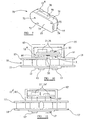
- the exemplary monitoring system is shown in relation to a transmission chain 10 (only a part of which is shown) comprising inner and outer link plates 11, 12 arranged in opposed pairs, one of the pair being disposed on each side of the chain (only one side of the chain is shown in figure 1 ).
- the chain 10 is articulated as the link plates 11, 12 are pivotally interconnected by transverse pins 13 that pass through aligned pin holes 14 in the overlapping inner and outer link plates on each side.
- the pins 14 are designed to be an interference, or friction, fit with the outer link plates 12 but a clearance fit with the inner link plates 11 so that the latter are free to pivot on the pins 13 relative to the outer link plates 12.
- One of the outer ink plates 12a of the transmission chain is fitted with a data collection device 15 that is provided with a visual indicator 25 and receiver and/or transmitter (hidden in figure 1 ) to enable communication by a wireless link with one of two controller types 16, 17.
- a first controller type 16 may be used simply to activate the data collection device 15 in a restricted mode of operation whereas a second controller type 17 of more sophisticated design can not only transmit information so as to configure and/or activate the device 15 but also can receive data collected by the device during or after operation of the chain 10 under load.
- the data collection device 15 is shown in more detail in figure 2 and comprises a sensor 20 for detecting physical parameters associated with the chain.
- the sensor 20 may comprise a strain gauge network that is bonded or otherwise fixed to the surface of the chain outer link plate 12a and generates analogue electrical output signals that are proportional to the elongation of the chain link plate 12a as a result of the chain load. The signals are therefore indicative of the load applied to the chain 10 at any point in time.
- Such signals are passed to signal processing circuitry including an amplifier 21 and are then converted into digital data by an Analogue to Digital converter (ADC) and passed to a microcontroller device 22 that includes a processor.
- ADC Analogue to Digital converter
- the data can be stored in a local memory 23 and/or transmitted when demanded by the controller 22 via an infra-red transmitter/receiver 24.
- the microcontroller 22 can be configured to perform a certain amount of data analysis locally and is connected to at least one visual indicator 25 that can indicate the status of the data collection device 15 and/or the condition of the chain 10 being monitored.
- a battery (not shown) is provided within the device to power the components.
- strain gauge network is simply provided as one example embodiment of the sensor and other sensors such as, for example, temperature or vibration transducers may be used instead, or in combination with, the strain gauges.
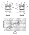
- the first controller type 16 shown in figure 1 and figure 3 , is a simple small fob device that comprises a button switch 26, a logic circuit 27 and an infra-red transmitter 28.
- the data collection device 15 is in a quiescent stand-by or "sleep" mode (mode 0) where there is low power consumption (see figure 5A ).
- Operating the switch transmits a signal to the data collection device 15 to switch it from the "sleep" mode (mode 0) to a first operative mode (mode 1) in which it simply compares the sensor output signal with a stored threshold value representing an upper limit of allowable chain load. (or alternative parameter) and operates visual indicator(s) 25 e.g. one or more LEDs.
- the output signal exceeds the stored threshold value and a signal is generated by the microcontroller 22 to illuminate the LED 25 so as to serve as a visual alarm.
- the visual indicator has two LEDs of differing colours, one (e.g. green) being illuminated when the data collection device is in operation (i.e. in mode 1) and the chain load is below the allowable upper limit and the other LED (e.g. red) being illuminated when the chain is overloaded (also in mode 1).
- the button switch 26 is also used to deactivate the device by switching it from mode 1 to mode 0 as shown in the second part of figure 5A .
- the second controller type 17, illustrated in figure 4 comprises a handheld unit having a microcontroller 31, a keypad 32, memory 33, an LCD display 34, an infra-red transmitter/receiver 35 and a connection 36 such as a USB connector for connection to a PC 37.
- the data collection device 15 can operate as a data logger and capture operating data over a period of time.
- the controller 17 is used to switch the data collection device 15 from a stand-by state (mode 0) as before to a data-logging mode (mode 2) whereby the sensor output data is recorded and time stamped.
- mode 0 stand-by state
- mode 2 data-logging mode
- the LED 25 can be illuminated as described above in relation to first controller 16.
- the device 15 can be switched back to mode 0.
- the data captured by the sensor 20 is transmitted via the infra-red transmitter/receiver 35 either in real time or after the event to the microcontroller 31 of the second controller type 17 and can be displayed on the LCD 34.
- a certain amount of processing and analysis of the data can be performed by the controller 31.
- the data may be downloaded to a PC 37 for analysis or further analysis.
- the transmission chain 10 can be supplied to a customer with the data collection device 15 fitted and accompanied with the first controller type 16.
- the customer is able identify when a chain has been overloaded by virtue of the visual indicator 25 on the chain 10 and take remedial action including, if necessary, replacing the chain.
- the customer requires a more sophisticated system he can purchase a second controller type 17 without having to replace the chain 10 or the data collection device 15.
- this second controller 17 the customer has access to more detailed information regarding chain performance and loading and is thus in a position to take more educated decisions in relation to the condition of the chain and to determine whether the chain needs servicing or replacing.
- the second controller 17 or of the data collection device 15 can be pre-loaded with data relating to the chain being analysed such as, for example, its type, length, certification and service history to date.
- This data may be pre-programmed into the memory 23, 33 associated with the processor of one or other of the microcontrollers 22, 31 before the chain is fitted to the drive. It may be entered from the keypad 32 of the second controller 17 or may be entered remotely from the PC 37.
- the data can be analysed, for example, to determine the average number of hours that the chain has been used in a particular range of load magnitudes. This information is more meaningful and useful to a chain user, or the machine owner in which the chain drive is incorporated, than a simple indication of how long the chain has been used and whether it has been overloaded. This is because for a significant proportion of the time in service the chain may not be carrying any significant load, depending on the application.
- the data can be analysed to determine the number of times the load has exceeded a predetermined threshold and/or the absolute value of those loads. This enables the user to determine how many times the recommended chain load has been exceeded and the impact this has on the risk of chain failure. Analysis of the data may also assist in diagnosis of faults in the chain drive such as, for example, excessive start-up tension etc.
- the service conditions of the chain can be analysed, for example, by applying Miner's Rule to the data collected so as to predict the remaining life span of the chain. This analysis involves the calculation of the fractional contribution to fatigue damage at each load level (and therefore stress level) in the load spectrum.
- the chain may be part of a lifting chain assembly of a fork-lift truck which is leased by the owner to a lessee. In such circumstances the lessor can download information when the truck is returned after the hire period.
- the work conditions of the chain can be monitored remotely during the use of the truck by means of a computer connected to a local or wide area network.
- the data stored in the memory can transmitted at periodic intervals to the lessor's computer network.
- the data is analysed by a software routine running on the computer network so as to generate meaningful results.
- a fixed remote controller is provided in proximity to the circulating chain e.g. a frame or part of the machinery to which the chain forms a part.
- the data collection device transmits data wirelessly as it passes in proximity to the remote monitor.
- data can be collected in the remote controller at regular intervals where it may be processed or downloaded for processing at a suitable future time or date.
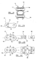
- FIG. 6 is a schematic representation illustrating the mechanical structure of the data collection device 15 and its position on the chain 10. It can be seen that device has a housing 40 that encloses the components shown in figure 2 and which is mounted to the outer link plate 12a by a convenient fixing.
- the housing 40 has an outwardly facing wall 41 that is penetrated by at least one aperture 42 in which the LED(s) 25 is (are) disposed so as to be easily visible in use.
- An upper wall 43 of the housing 40 has a window 44 via which IR signals are transmitted.
- the sensor 20, in the form of a strain gauge network, is mounted on the inwardly facing surface 45 of the outer link 12a and is connected to electronic signal processing circuitry (21, ADC etc.) within the housing 40.
- Figure 7 shows an exemplary housing 40 having upper 50, lower 51, front 52, side walls 53.
- the front wall 51 has three apertures 54 that each receives an LED 25 of the data collection device 15, and a slot for accommodating a manual override switch 55 of the device.
- the housing 40 is adapted to be connected to an outer link by means of an L-shaped connector bracket 56 having a first planar plate (hidden) whose plane extends in parallel to the outer link plate 11 (and therefore the front wall 52 of the housing 40 and is connected to the outer link plate 11 by any appropriate fixing means and a perpendicular plate 57 that is fixed to the upper wall 50 of the housing 40 by clips 58.
- FIG 8 An alternative housing and connection arrangement is shown in figure 8 .
- the housing 60 is depicted with a single chain link 61 and only the outer link plates 12, 12a and pins 13 are shown.
- the pins 13 are extended in length compared to those of a conventional chain such that they project laterally beyond the plane of one of the outer link plates 12a and are connected to a suitable retaining structure (hidden) fixed inside the housing 60.
- the front wall 71 is removable to obtain access to the interior of the data collection device 15.
- the wall is penetrated by two fixing holes 72 and an LED aperture 73.
- a clip mechanism 74 also serves to secure the front wall 71 to one the side walls 75.
- the upper and lower walls 76, 77 each have a rearwardly protruding clip 78 (only one shown, the other being hidden) that connects to the periphery of an outer link plate 12a.
- the upper wall 76 has a window 79 to allow the passage of infra red signals.
- FIGS. 10 and 11 Further embodiments of the connection and structure of the data collection device 15 and its housing are shown in figures 10 and 11 in relation to a roller bush chain 10.
- the chain outer link plate 12a that supports the device 15 has pins 13 that are extended in comparison to a standard link and are received in a pair of apertures 80 in a rear wall 81 of the housing 82.
- the outer link plate 12a is mounted on to the end of the extended pins 13 is fully enclosed within the housing 82.
- the outer link plate 12a supports a board 83 on which the electronic components 21 to 24 of the data collection device 15 are mounted with the exception of the strain gauge sensors 20 which are fixed directly to the outer link plate 12a. It will be noted that the visual indicator is not shown in this particular figure.
- a rear wall 81' of the housing 82' serves also as the outer link plate 12a' and therefore the extended pins 13' pass therethough.
- the mounting board 83' for the electronic components 21' to 24' is supported on the ends of the pins 13'. Again the visual indicator is not shown in this figure.
- the strain gauges used in the present invention are of conventional design in that they each comprise a very fine metallic wire whose electrical resistance varies in proportion to the amount of strain to which it is subjected.
- the gauges are typically mounted on a substrate that is bonded or to the link plate.
- the substrate may take the form of, for example, a film, foil or silicon wafer.
- the strain experienced by the link plate to which the substrate is fixed is transferred directly to the strain gauges.
- To measure the small changes in resistance of the gauges they are arranged in a conventional bridge network such as a Wheatstone Bridge where each gauge forms an arm of the bridge network and an excitation supply voltage. Any change in resistance of a gauge is reflected in a non-zero output voltage.
- Figures 12 to 15 relate to the positioning of the strain gauge sensors 20 on the chain link plate.
- Figures 12A and 12B show part of a prior art roller chain 10 in an unloaded and loaded condition respectively.
- the chain 10 comprises opposed outer link plates 12 alternating along the length of the chain with opposed inner link plates 11 and being pivotally connected therewith by transverse pins 13 that pass through aligned pin hole apertures 14 in overlapping plates 11, 12.
- a bush 90 extends between opposed apertures 14 in the inner link plates 11 on each side and receives a transverse pin 13.
- a cylindrical roller 91 is rotatably mounted on the bush 90. It will be seen from a comparison of the two figures that when the chain is loaded in tension the pins 13 are subjected to a bending moment.
- the latter In order to avoid damage to the strain gauges when mounted on the inside surface 92 of the outer link 12 the latter has to be mounted such that it is clear of rubbing contact with the outer surface of the inner link plates 11. This may be achieved by, for example, using the housing configurations shown in figures 10 and 11 or by adopting a bush 94 that extends beyond the inner link plate 11 at least on the side of the chain where the gauges 95 are mounted as shown in figure 14 .
- strain gauges 95 on an outer chain link plate 12 is shown in figure 15A alongside figures 15B and 15C , which illustrate the positions in accordance with the present invention.
- the position illustrated in figure 15A is the most intuitive since it is close to the pins holes 14 where tensile stress tends to be concentrated.
- the bush 94 of figure 14 or an alternative spacer, is used it would rub against the gauges 95.
- the gauges 95 are to be fixed to the inner surface 92 of the outer link plate 12 this has to be done before the plate is attached to the pins 13 otherwise it is very difficult if not impossible to achieve in view of the confined space.
- the gauges 95 are arranged into a Wheatstone Bridge network with each gauge forming one arm of the bridge network as described above.
- the bridge is excited by a supply voltage derived from the battery and the output voltage is representative to the strain on the link plate.
- the gauges are arranged into two sets of two, the gauges of each set being arranged orthogonally. This is shown in figure 15C where the gauges 95 are arranged on to a single substrate 96, with two alternative gauge arrangements on that film being depicted to the right of that figure.
- the stain gauge substrate 96 is arranged on the centre line c of the link plate 12 equidistant from the pin hole centres 14.
- the arrows illustrate the direction of strain to which the particular gauge 95 is responsive.
- two of the gauges that detect strain in the same direction are disposed on the centre line of the chain whereas the other two are disposed such that they are symmetrically disposed about the centreline c and a line that extends perpendicular to the centre line c at the position mid-way along the pitch distance P.
- each set of gauges 95 are arranged into a half bridge network (with two gauges) or may simply be a single gauge.
- any appropriate form of sensor or transducer may be used as an alternative to a strain gauge for sensing any appropriate physical condition of the chain besides stress or strain e.g. temperature, vibration etc.
Landscapes
- Physics & Mathematics (AREA)
- General Physics & Mathematics (AREA)
- Chemical & Material Sciences (AREA)
- Analytical Chemistry (AREA)
- Arrangements For Transmission Of Measured Signals (AREA)
- Devices For Conveying Motion By Means Of Endless Flexible Members (AREA)
- Force Measurement Appropriate To Specific Purposes (AREA)
- Maintenance And Management Of Digital Transmission (AREA)
- Testing Or Calibration Of Command Recording Devices (AREA)
- Investigating Strength Of Materials By Application Of Mechanical Stress (AREA)
- Length Measuring Devices With Unspecified Measuring Means (AREA)
- Measurement Of Length, Angles, Or The Like Using Electric Or Magnetic Means (AREA)
Applications Claiming Priority (2)
| Application Number | Priority Date | Filing Date | Title |
|---|---|---|---|
| GBGB0515176.6A GB0515176D0 (en) | 2005-07-23 | 2005-07-23 | Transmission chain monitoring system |
| PCT/GB2006/002383 WO2007012796A1 (en) | 2005-07-23 | 2006-06-28 | Transmission chain monitoring system |
Publications (2)
| Publication Number | Publication Date |
|---|---|
| EP1907810A1 EP1907810A1 (en) | 2008-04-09 |
| EP1907810B1 true EP1907810B1 (en) | 2011-04-27 |
Family
ID=34976474
Family Applications (1)
| Application Number | Title | Priority Date | Filing Date |
|---|---|---|---|
| EP06755663A Not-in-force EP1907810B1 (en) | 2005-07-23 | 2006-06-28 | Transmission chain monitoring system |
Country Status (8)
Cited By (1)
| Publication number | Priority date | Publication date | Assignee | Title |
|---|---|---|---|---|
| CN103619157A (zh) * | 2013-12-11 | 2014-03-05 | 深圳市唐德机械有限公司 | 自动插件机尾端链条启动结构 |
Families Citing this family (35)
| Publication number | Priority date | Publication date | Assignee | Title |
|---|---|---|---|---|
| GB0515176D0 (en) * | 2005-07-23 | 2005-08-31 | Renold Plc | Transmission chain monitoring system |
| US8063886B2 (en) * | 2006-07-18 | 2011-11-22 | Iee International Electronics & Engineering S.A. | Data input device |
| GB0719804D0 (en) * | 2007-09-29 | 2007-11-21 | Renold Plc | Transmission chain wear monitoring |
| WO2009047282A1 (en) * | 2007-10-12 | 2009-04-16 | Rexnord Marbett S.R.L. | A system and a method for remotely monitoring the operational life of conveyors of articles |
| JP5270404B2 (ja) * | 2009-03-05 | 2013-08-21 | 東京製綱株式会社 | ワイヤロープ寿命管理装置および方法 |
| US8387777B2 (en) | 2009-10-06 | 2013-03-05 | Ecolab Usa Inc. | Conveyor chain tension monitor |
| JP5540728B2 (ja) * | 2010-01-25 | 2014-07-02 | 株式会社ジェイテクト | ころ軸受装置 |
| US8191703B2 (en) | 2010-02-18 | 2012-06-05 | Ecolab Usa Inc. | Conveyor system monitoring and maintenance |
| US9241820B2 (en) * | 2010-12-16 | 2016-01-26 | Richard A. Graham | Pneumatic joint separator for lower body alignment |
| US10285891B2 (en) | 2010-12-16 | 2019-05-14 | Richard A. Graham | Pneumatic joint separator for lower body alignment |
| DE102011018535A1 (de) * | 2011-04-26 | 2012-10-31 | Liebherr-Components Biberach Gmbh | Seilprüfstand |
| US20130190121A1 (en) * | 2012-01-05 | 2013-07-25 | The Timken Company | Roller chain welded extended pin |
| US20130279298A1 (en) * | 2012-04-19 | 2013-10-24 | William Mark PRENTICE | Monitoring of underwater mooring lines |
| DE102012112947B3 (de) * | 2012-12-21 | 2013-11-07 | Thiele Gmbh & Co. Kg | Montageverfahren für einen Dehnmessstreifen |
| WO2014199376A1 (en) | 2013-06-10 | 2014-12-18 | Danimar Ltd. | Device and method for monitoring a chain parameter |
| US9404566B2 (en) * | 2013-09-05 | 2016-08-02 | Randal Salvatore | Power measurement system based on self-limiting force |
| FI127826B (en) | 2014-08-01 | 2019-03-15 | Konecranes Oyj | Method of detecting a worn link in a chain, and lifting device |
| DE102015009431A1 (de) * | 2015-07-21 | 2017-01-26 | Iwis Antriebssysteme Gmbh & Co. Kg | Gelenkkette mit einem passiven Oberflächenwellen-Sensor |
| US9791357B2 (en) | 2015-07-28 | 2017-10-17 | Jpw Industries Inc. | Overload indicator for hoist |
| JP6790339B2 (ja) * | 2015-08-24 | 2020-11-25 | 横浜ゴム株式会社 | コンベヤベルトのモニタリングシステム |
| CN105352714A (zh) * | 2015-11-23 | 2016-02-24 | 苏州顺革智能科技有限公司 | 一种链条紧目检测装置 |
| CN109477550B (zh) * | 2016-01-28 | 2020-11-06 | 易格斯有限公司 | 具有劣化电检测的线路引导装置及用于该线路引导装置的无线电电路 |
| CN105784241B (zh) * | 2016-03-07 | 2018-04-13 | 中国矿业大学 | 一种刮板输送机链条张力估算方法 |
| DE202016107317U1 (de) * | 2016-12-23 | 2017-03-27 | Igus Gmbh | Systeme zur Überwachung des Betriebs einer Energieführungskette |
| DE102017105031A1 (de) * | 2017-03-09 | 2018-09-13 | ABUS August Bremicker Söhne KG | Gelenkschloss mit Alarmeinrichtung |
| EP3596356B1 (en) * | 2017-03-14 | 2023-05-03 | Evoqua Water Technologies LLC | A settling basin of a wastewater treatment system |
| US9869072B1 (en) * | 2017-04-12 | 2018-01-16 | Caterpillar Inc. | Dragline chain |
| US10406397B1 (en) | 2018-06-18 | 2019-09-10 | Richard A. Graham | Joint separator for body alignment |
| DE102019116534B3 (de) * | 2019-06-18 | 2020-07-23 | Thiele Gmbh & Co. Kg | Kettenkraftmessung an Kettenförderern |
| CA3155000A1 (en) * | 2019-10-16 | 2021-04-22 | Richard V. Campbell | Intelligent fiber rope termination, module, and networking technologies |
| GB2609274B (en) * | 2020-03-11 | 2023-09-27 | Stanley Weller Keith | Method and apparatus for measuring rowing skill |
| US11976999B2 (en) * | 2020-07-02 | 2024-05-07 | U.S. Tsubaki Holdings, Inc. | Chain monitoring systems and methods |
| EP3960665A1 (de) * | 2020-08-28 | 2022-03-02 | Siemens Aktiengesellschaft | Verfahren und system zum erkennen von anomalien beim betrieb eines fördersystems, insbesondere eines flughafen-gepäckkarussells |
| CN113092104A (zh) * | 2021-04-09 | 2021-07-09 | 重庆大学 | 一种蜗轮母机电子传动链性能检测系统及方法 |
| CN113933051B (zh) * | 2021-09-08 | 2024-03-15 | 山东金恒力机械制造有限公司 | 一种用于特种高强度链条的测试装置 |
Citations (1)
| Publication number | Priority date | Publication date | Assignee | Title |
|---|---|---|---|---|
| US4566339A (en) * | 1983-12-23 | 1986-01-28 | Southern Systems, Inc. | Chain pull monitor system |
Family Cites Families (49)
| Publication number | Priority date | Publication date | Assignee | Title |
|---|---|---|---|---|
| US1528154A (en) | 1924-05-31 | 1925-03-03 | Joseph S Dickson | Amusement device |
| DE2504445C2 (de) | 1975-02-04 | 1977-03-24 | Krueger & Co Kg | Vorrichtung zur ueberwachung des lastmomentes eines verstellbaren kranauslegers |
| GB1484954A (en) | 1975-07-23 | 1977-09-08 | Nippon Konbeya Kk | Device for detecting elongation of a conveyor belt joint |
| US4106005A (en) | 1976-05-14 | 1978-08-08 | Nippon Konbeya Kabushiki Kaisha | Apparatus for detecting elongation of a joint of a conveyor belt |
| GB2041549B (en) * | 1979-02-02 | 1983-08-17 | Post Office | Measuring tension in chains |
| DE3145115C2 (de) | 1981-11-13 | 1983-12-08 | Dr.Ing.H.C. F. Porsche Ag, 7000 Stuttgart | "Hydraulischer Kettenspanner" |
| SU1063739A1 (ru) | 1982-06-30 | 1983-12-30 | Всесоюзный научно-исследовательский и проектно-конструкторский институт подъемно-транспортного машиностроения | Устройство дл контрол износа цепи подвесного конвейера |
| JPS5943322A (ja) * | 1982-09-06 | 1984-03-10 | Hitachi Ltd | トルク検出方法 |
| JPS5978007A (ja) | 1982-10-27 | 1984-05-04 | Tsubakimoto Chain Co | コンベヤ駆動チエ−ンの延び検出装置 |
| DE3524338A1 (de) | 1985-07-08 | 1987-01-15 | Teske Lothar | Verschleissanzeige fuer trogkettenfoerderer |
| JPS6438043A (en) | 1987-04-09 | 1989-02-08 | Asahi Chemical Ind | Novel process for production of ethers |
| US4949263A (en) | 1987-06-01 | 1990-08-14 | Alert-O-Brake Systems Inc. | Load handling vehicle monitoring system |
| JPS6422714A (en) | 1987-07-20 | 1989-01-25 | Honda Motor Co Ltd | Overhead conveyor having function for inspecting elongation |
| US4826470A (en) | 1988-07-01 | 1989-05-02 | Eaton Corporation | Fluid operated chain or belt tensioning device |
| DE3832512C1 (en) | 1988-09-24 | 1990-04-26 | Bayerische Motoren Werke Ag, 8000 Muenchen, De | Tensioning device for an endless flexible transmission |
| JPH02130402A (ja) | 1988-11-10 | 1990-05-18 | Nkk Corp | リンクチェーンコンベアの摩耗伸び測定方法 |
| GB2246199B (en) | 1990-07-16 | 1994-02-09 | Hugh Michael Oppen Pratt | Load measuring device |
| DE4103055A1 (de) | 1991-02-01 | 1992-08-06 | Schaeffler Waelzlager Kg | Hydraulisches spielausgleichselement fuer den einsatz von brennkraftmaschinen |
| US5207108A (en) * | 1991-06-07 | 1993-05-04 | Tassic William P | Transducer for sensing tension loading of a conveyor chain |
| US5272924A (en) | 1991-11-05 | 1993-12-28 | William P. Tassic | System and method for monitoring tension loading of a conveyor chain |
| JPH0550214U (ja) | 1991-12-12 | 1993-07-02 | 株式会社椿本チエイン | オイルによって空気侵入経路をシールしたオイル作動式テンショナ |
| JPH082565Y2 (ja) | 1992-03-31 | 1996-01-29 | 株式会社椿本チエイン | 無端移動体の伸び測定装置 |
| JP3126811B2 (ja) * | 1992-06-16 | 2001-01-22 | 本田技研工業株式会社 | 金属vベルトの作用力検出用金属ブロックおよびこれを用いた作用力検出装置 |
| US5370584A (en) | 1993-01-15 | 1994-12-06 | Borg-Warner Automotive, Inc. | Piston design for removing air from a hydraulic tensioner |
| JP2682951B2 (ja) | 1993-10-12 | 1997-11-26 | 住友建機株式会社 | ジブ起伏ロープの寿命判定装置 |
| JP2748836B2 (ja) | 1993-12-16 | 1998-05-13 | 日本鋼管株式会社 | クレーン用ワイヤーロープの寿命予測方法及びその装置 |
| JPH07280049A (ja) | 1994-04-12 | 1995-10-27 | Tsubakimoto Chain Co | 摺動面に螺旋状溝を設けたオイル式テンショナ |
| US5563392A (en) | 1995-04-12 | 1996-10-08 | Patco Sales & Service, Inc. | Method and apparatus for monitoring wear of a continuous chain |
| DE19610483A1 (de) | 1996-03-16 | 1997-09-18 | Wagner Foerdertechnik | Betriebsdatenerfassungsgerät für ein Flurförderzeug |
| JPH102386A (ja) | 1996-06-13 | 1998-01-06 | Tsubakimoto Chain Co | 緩衝機構付ラチェット式テンショナ |
| US5824963A (en) | 1997-03-04 | 1998-10-20 | Gagetek Company | Lifting device employing a weight integrative weighing system |
| JP3635198B2 (ja) | 1997-12-22 | 2005-04-06 | Ntn株式会社 | チェーンテンショナ |
| JPH11201245A (ja) | 1998-01-12 | 1999-07-27 | Ntn Corp | チェーンテンショナ |
| US6126563A (en) | 1998-09-21 | 2000-10-03 | Borgwarner Inc. | Quick purge tensioner with internal piston spring |
| US6053831A (en) | 1998-12-08 | 2000-04-25 | Borg-Warner Automotive, Inc. | Hydraulic tensioner with passage of variable cross-section between the piston and bore |
| JP2001021013A (ja) | 1999-07-06 | 2001-01-26 | Borg Warner Automotive Kk | 液圧テンショナ |
| DE19959594C1 (de) | 1999-12-10 | 2001-06-21 | Bayerische Motoren Werke Ag | Kettentrieb eines V-Motors mit obenliegenden Nockenwellen |
| JP3687956B2 (ja) | 2001-01-25 | 2005-08-24 | 株式会社椿本チエイン | 圧力油室を有するラチェット式テンショナ |
| JP4141649B2 (ja) | 2001-02-20 | 2008-08-27 | 三菱電機ビルテクノサービス株式会社 | 乗客コンベヤの踏段チェーンの伸び量測定装置 |
| JP2004521044A (ja) * | 2001-02-23 | 2004-07-15 | レノルド ピーエルシー | 負荷コンベヤを使用する際の負荷監視及び在庫管理システム |
| GB2377918B (en) | 2001-07-24 | 2006-02-01 | Renold Plc | Chain elongation monitoring apparatus and method |
| US6609985B2 (en) * | 2001-11-07 | 2003-08-26 | Borgwarner Inc. | Tensioner with vibrational damping |
| DE10155364A1 (de) | 2001-11-10 | 2003-05-22 | Bayerische Motoren Werke Ag | Hydraulische Spannvorrichtung für ein Zugmittelgetriebe, insbesondere Ketten- oder Riementriebe von Brennkraftmaschinen |
| JP4047604B2 (ja) * | 2002-03-15 | 2008-02-13 | 鉱研工業株式会社 | 杭耐力測定装置 |
| US6865955B2 (en) | 2003-06-02 | 2005-03-15 | Daimlerchrysler Corporation | Conveyor diagnostic system |
| GB0316575D0 (en) | 2003-07-16 | 2003-08-20 | Renold Plc | Tensioner for a chain or belt |
| JP2006071452A (ja) * | 2004-09-02 | 2006-03-16 | Tsubakimoto Chain Co | チェーン稼働状態測定装置 |
| JP2006162281A (ja) * | 2004-12-02 | 2006-06-22 | Tsubakimoto Chain Co | 測定装置 |
| GB0515176D0 (en) * | 2005-07-23 | 2005-08-31 | Renold Plc | Transmission chain monitoring system |
-
2005
- 2005-07-23 GB GBGB0515176.6A patent/GB0515176D0/en not_active Ceased
-
2006
- 2006-06-28 ES ES06755663T patent/ES2363723T3/es active Active
- 2006-06-28 US US11/996,338 patent/US7634949B2/en not_active Expired - Fee Related
- 2006-06-28 DE DE602006021577T patent/DE602006021577D1/de active Active
- 2006-06-28 JP JP2008523429A patent/JP4864085B2/ja not_active Expired - Fee Related
- 2006-06-28 WO PCT/GB2006/002383 patent/WO2007012796A1/en not_active Application Discontinuation
- 2006-06-28 AT AT06755663T patent/ATE507466T1/de active
- 2006-06-28 EP EP06755663A patent/EP1907810B1/en not_active Not-in-force
-
2009
- 2009-09-01 US US12/552,009 patent/US7886613B2/en not_active Expired - Fee Related
Patent Citations (1)
| Publication number | Priority date | Publication date | Assignee | Title |
|---|---|---|---|---|
| US4566339A (en) * | 1983-12-23 | 1986-01-28 | Southern Systems, Inc. | Chain pull monitor system |
Cited By (1)
| Publication number | Priority date | Publication date | Assignee | Title |
|---|---|---|---|---|
| CN103619157A (zh) * | 2013-12-11 | 2014-03-05 | 深圳市唐德机械有限公司 | 自动插件机尾端链条启动结构 |
Also Published As
| Publication number | Publication date |
|---|---|
| JP4864085B2 (ja) | 2012-01-25 |
| GB0515176D0 (en) | 2005-08-31 |
| US20080214344A1 (en) | 2008-09-04 |
| ATE507466T1 (de) | 2011-05-15 |
| WO2007012796A1 (en) | 2007-02-01 |
| ES2363723T3 (es) | 2011-08-12 |
| EP1907810A1 (en) | 2008-04-09 |
| US7634949B2 (en) | 2009-12-22 |
| DE602006021577D1 (de) | 2011-06-09 |
| US7886613B2 (en) | 2011-02-15 |
| US20100005899A1 (en) | 2010-01-14 |
| JP2009503484A (ja) | 2009-01-29 |
Similar Documents
| Publication | Publication Date | Title |
|---|---|---|
| EP1907810B1 (en) | Transmission chain monitoring system | |
| KR100936120B1 (ko) | 로울러형 하중검출장치를 이용한 크레인의 안전제어시스템 | |
| EP1362003B1 (en) | A load monitoring system for use with a load conveyor | |
| EP3126809B1 (en) | Vibration testing system and methodology | |
| WO2009044117A1 (en) | Transmission chain wear monitoring | |
| US20230287990A1 (en) | Smart Valve Adaptor with Integrated Electronics | |
| AU2016339999B2 (en) | Electronic roundsling inspection, load monitoring and warning system | |
| US6865955B2 (en) | Conveyor diagnostic system | |
| KR20120080792A (ko) | 로드셀 모니터링 장치 및 방법 | |
| US20240328461A1 (en) | Device for monitoring the lubrication condition of a bearing of a track roller of a running gear of a tracked vehicle | |
| US11486793B2 (en) | Electric drive unit having intelligent maintenance requirement monitoring | |
| CN211998575U (zh) | 起重量限制器及起升设备 | |
| US20140014887A1 (en) | Good-grip winch for handling loads | |
| KR20080075966A (ko) | 차량 중량 측정장치 | |
| JPH04273032A (ja) | 駆動装置のねじれ振動による状態量を監視するための監視装置 | |
| WO2010041053A2 (en) | Servicing monitor | |
| WO2016063755A1 (ja) | ベルトシステムの状態判定システム | |
| JP2002095219A (ja) | モータの運転状況モニタシステム | |
| KR20210077325A (ko) | 자가진단기능이 구비된 상시감시형 저전력 무선 센서노드 | |
| KR20100024314A (ko) | 자동차 정비 시스템 |
Legal Events
| Date | Code | Title | Description |
|---|---|---|---|
| PUAI | Public reference made under article 153(3) epc to a published international application that has entered the european phase |
Free format text: ORIGINAL CODE: 0009012 |
|
| 17P | Request for examination filed |
Effective date: 20080123 |
|
| AK | Designated contracting states |
Kind code of ref document: A1 Designated state(s): AT BE BG CH CY CZ DE DK EE ES FI FR GB GR HU IE IS IT LI LT LU LV MC NL PL PT RO SE SI SK TR |
|
| 17Q | First examination report despatched |
Effective date: 20100929 |
|
| GRAP | Despatch of communication of intention to grant a patent |
Free format text: ORIGINAL CODE: EPIDOSNIGR1 |
|
| GRAS | Grant fee paid |
Free format text: ORIGINAL CODE: EPIDOSNIGR3 |
|
| GRAA | (expected) grant |
Free format text: ORIGINAL CODE: 0009210 |
|
| AK | Designated contracting states |
Kind code of ref document: B1 Designated state(s): AT BE BG CH CY CZ DE DK EE ES FI FR GB GR HU IE IS IT LI LT LU LV MC NL PL PT RO SE SI SK TR |
|
| REG | Reference to a national code |
Ref country code: GB Ref legal event code: FG4D |
|
| REG | Reference to a national code |
Ref country code: CH Ref legal event code: EP |
|
| REG | Reference to a national code |
Ref country code: IE Ref legal event code: FG4D |
|
| REF | Corresponds to: |
Ref document number: 602006021577 Country of ref document: DE Date of ref document: 20110609 Kind code of ref document: P |
|
| REG | Reference to a national code |
Ref country code: DE Ref legal event code: R096 Ref document number: 602006021577 Country of ref document: DE Effective date: 20110609 |
|
| REG | Reference to a national code |
Ref country code: NL Ref legal event code: VDEP Effective date: 20110427 |
|
| REG | Reference to a national code |
Ref country code: ES Ref legal event code: FG2A Ref document number: 2363723 Country of ref document: ES Kind code of ref document: T3 Effective date: 20110812 |
|
| REG | Reference to a national code |
Ref country code: SE Ref legal event code: TRGR |
|
| LTIE | Lt: invalidation of european patent or patent extension |
Effective date: 20110427 |
|
| PG25 | Lapsed in a contracting state [announced via postgrant information from national office to epo] |
Ref country code: PT Free format text: LAPSE BECAUSE OF FAILURE TO SUBMIT A TRANSLATION OF THE DESCRIPTION OR TO PAY THE FEE WITHIN THE PRESCRIBED TIME-LIMIT Effective date: 20110829 Ref country code: LT Free format text: LAPSE BECAUSE OF FAILURE TO SUBMIT A TRANSLATION OF THE DESCRIPTION OR TO PAY THE FEE WITHIN THE PRESCRIBED TIME-LIMIT Effective date: 20110427 |
|
| PG25 | Lapsed in a contracting state [announced via postgrant information from national office to epo] |
Ref country code: SI Free format text: LAPSE BECAUSE OF FAILURE TO SUBMIT A TRANSLATION OF THE DESCRIPTION OR TO PAY THE FEE WITHIN THE PRESCRIBED TIME-LIMIT Effective date: 20110427 Ref country code: IS Free format text: LAPSE BECAUSE OF FAILURE TO SUBMIT A TRANSLATION OF THE DESCRIPTION OR TO PAY THE FEE WITHIN THE PRESCRIBED TIME-LIMIT Effective date: 20110827 Ref country code: GR Free format text: LAPSE BECAUSE OF FAILURE TO SUBMIT A TRANSLATION OF THE DESCRIPTION OR TO PAY THE FEE WITHIN THE PRESCRIBED TIME-LIMIT Effective date: 20110728 Ref country code: LV Free format text: LAPSE BECAUSE OF FAILURE TO SUBMIT A TRANSLATION OF THE DESCRIPTION OR TO PAY THE FEE WITHIN THE PRESCRIBED TIME-LIMIT Effective date: 20110427 Ref country code: FI Free format text: LAPSE BECAUSE OF FAILURE TO SUBMIT A TRANSLATION OF THE DESCRIPTION OR TO PAY THE FEE WITHIN THE PRESCRIBED TIME-LIMIT Effective date: 20110427 Ref country code: CY Free format text: LAPSE BECAUSE OF FAILURE TO SUBMIT A TRANSLATION OF THE DESCRIPTION OR TO PAY THE FEE WITHIN THE PRESCRIBED TIME-LIMIT Effective date: 20110427 |
|
| PG25 | Lapsed in a contracting state [announced via postgrant information from national office to epo] |
Ref country code: NL Free format text: LAPSE BECAUSE OF FAILURE TO SUBMIT A TRANSLATION OF THE DESCRIPTION OR TO PAY THE FEE WITHIN THE PRESCRIBED TIME-LIMIT Effective date: 20110427 |
|
| PG25 | Lapsed in a contracting state [announced via postgrant information from national office to epo] |
Ref country code: EE Free format text: LAPSE BECAUSE OF FAILURE TO SUBMIT A TRANSLATION OF THE DESCRIPTION OR TO PAY THE FEE WITHIN THE PRESCRIBED TIME-LIMIT Effective date: 20110427 Ref country code: CZ Free format text: LAPSE BECAUSE OF FAILURE TO SUBMIT A TRANSLATION OF THE DESCRIPTION OR TO PAY THE FEE WITHIN THE PRESCRIBED TIME-LIMIT Effective date: 20110427 |
|
| REG | Reference to a national code |
Ref country code: CH Ref legal event code: PL |
|
| PG25 | Lapsed in a contracting state [announced via postgrant information from national office to epo] |
Ref country code: DK Free format text: LAPSE BECAUSE OF FAILURE TO SUBMIT A TRANSLATION OF THE DESCRIPTION OR TO PAY THE FEE WITHIN THE PRESCRIBED TIME-LIMIT Effective date: 20110427 Ref country code: RO Free format text: LAPSE BECAUSE OF FAILURE TO SUBMIT A TRANSLATION OF THE DESCRIPTION OR TO PAY THE FEE WITHIN THE PRESCRIBED TIME-LIMIT Effective date: 20110427 Ref country code: SK Free format text: LAPSE BECAUSE OF FAILURE TO SUBMIT A TRANSLATION OF THE DESCRIPTION OR TO PAY THE FEE WITHIN THE PRESCRIBED TIME-LIMIT Effective date: 20110427 Ref country code: PL Free format text: LAPSE BECAUSE OF FAILURE TO SUBMIT A TRANSLATION OF THE DESCRIPTION OR TO PAY THE FEE WITHIN THE PRESCRIBED TIME-LIMIT Effective date: 20110427 |
|
| PLBE | No opposition filed within time limit |
Free format text: ORIGINAL CODE: 0009261 |
|
| STAA | Information on the status of an ep patent application or granted ep patent |
Free format text: STATUS: NO OPPOSITION FILED WITHIN TIME LIMIT |
|
| REG | Reference to a national code |
Ref country code: IE Ref legal event code: MM4A |
|
| 26N | No opposition filed |
Effective date: 20120130 |
|
| PG25 | Lapsed in a contracting state [announced via postgrant information from national office to epo] |
Ref country code: CH Free format text: LAPSE BECAUSE OF NON-PAYMENT OF DUE FEES Effective date: 20110630 Ref country code: LI Free format text: LAPSE BECAUSE OF NON-PAYMENT OF DUE FEES Effective date: 20110630 Ref country code: IE Free format text: LAPSE BECAUSE OF NON-PAYMENT OF DUE FEES Effective date: 20110628 |
|
| REG | Reference to a national code |
Ref country code: DE Ref legal event code: R097 Ref document number: 602006021577 Country of ref document: DE Effective date: 20120130 |
|
| PGFP | Annual fee paid to national office [announced via postgrant information from national office to epo] |
Ref country code: ES Payment date: 20120726 Year of fee payment: 7 |
|
| PGFP | Annual fee paid to national office [announced via postgrant information from national office to epo] |
Ref country code: AT Payment date: 20120529 Year of fee payment: 7 |
|
| PG25 | Lapsed in a contracting state [announced via postgrant information from national office to epo] |
Ref country code: MC Free format text: LAPSE BECAUSE OF NON-PAYMENT OF DUE FEES Effective date: 20110630 |
|
| PG25 | Lapsed in a contracting state [announced via postgrant information from national office to epo] |
Ref country code: LU Free format text: LAPSE BECAUSE OF NON-PAYMENT OF DUE FEES Effective date: 20110628 |
|
| PG25 | Lapsed in a contracting state [announced via postgrant information from national office to epo] |
Ref country code: BG Free format text: LAPSE BECAUSE OF FAILURE TO SUBMIT A TRANSLATION OF THE DESCRIPTION OR TO PAY THE FEE WITHIN THE PRESCRIBED TIME-LIMIT Effective date: 20110727 |
|
| PGFP | Annual fee paid to national office [announced via postgrant information from national office to epo] |
Ref country code: SE Payment date: 20130612 Year of fee payment: 8 |
|
| PG25 | Lapsed in a contracting state [announced via postgrant information from national office to epo] |
Ref country code: TR Free format text: LAPSE BECAUSE OF FAILURE TO SUBMIT A TRANSLATION OF THE DESCRIPTION OR TO PAY THE FEE WITHIN THE PRESCRIBED TIME-LIMIT Effective date: 20110427 |
|
| PGFP | Annual fee paid to national office [announced via postgrant information from national office to epo] |
Ref country code: BE Payment date: 20130614 Year of fee payment: 8 |
|
| PG25 | Lapsed in a contracting state [announced via postgrant information from national office to epo] |
Ref country code: HU Free format text: LAPSE BECAUSE OF FAILURE TO SUBMIT A TRANSLATION OF THE DESCRIPTION OR TO PAY THE FEE WITHIN THE PRESCRIBED TIME-LIMIT Effective date: 20110427 |
|
| PG25 | Lapsed in a contracting state [announced via postgrant information from national office to epo] |
Ref country code: SE Free format text: LAPSE BECAUSE OF NON-PAYMENT OF DUE FEES Effective date: 20140629 |
|
| REG | Reference to a national code |
Ref country code: SE Ref legal event code: EUG |
|
| REG | Reference to a national code |
Ref country code: AT Ref legal event code: MM01 Ref document number: 507466 Country of ref document: AT Kind code of ref document: T Effective date: 20140628 |
|
| PG25 | Lapsed in a contracting state [announced via postgrant information from national office to epo] |
Ref country code: AT Free format text: LAPSE BECAUSE OF NON-PAYMENT OF DUE FEES Effective date: 20140628 |
|
| REG | Reference to a national code |
Ref country code: ES Ref legal event code: FD2A Effective date: 20150806 |
|
| PG25 | Lapsed in a contracting state [announced via postgrant information from national office to epo] |
Ref country code: ES Free format text: LAPSE BECAUSE OF NON-PAYMENT OF DUE FEES Effective date: 20140629 |
|
| REG | Reference to a national code |
Ref country code: FR Ref legal event code: PLFP Year of fee payment: 11 |
|
| REG | Reference to a national code |
Ref country code: FR Ref legal event code: PLFP Year of fee payment: 12 |
|
| PG25 | Lapsed in a contracting state [announced via postgrant information from national office to epo] |
Ref country code: BE Free format text: LAPSE BECAUSE OF NON-PAYMENT OF DUE FEES Effective date: 20140630 |
|
| REG | Reference to a national code |
Ref country code: FR Ref legal event code: PLFP Year of fee payment: 13 |
|
| PGFP | Annual fee paid to national office [announced via postgrant information from national office to epo] |
Ref country code: DE Payment date: 20200617 Year of fee payment: 15 Ref country code: FR Payment date: 20200512 Year of fee payment: 15 |
|
| PGFP | Annual fee paid to national office [announced via postgrant information from national office to epo] |
Ref country code: GB Payment date: 20200617 Year of fee payment: 15 Ref country code: IT Payment date: 20200512 Year of fee payment: 15 |
|
| REG | Reference to a national code |
Ref country code: DE Ref legal event code: R119 Ref document number: 602006021577 Country of ref document: DE |
|
| GBPC | Gb: european patent ceased through non-payment of renewal fee |
Effective date: 20210628 |
|
| PG25 | Lapsed in a contracting state [announced via postgrant information from national office to epo] |
Ref country code: GB Free format text: LAPSE BECAUSE OF NON-PAYMENT OF DUE FEES Effective date: 20210628 Ref country code: DE Free format text: LAPSE BECAUSE OF NON-PAYMENT OF DUE FEES Effective date: 20220101 |
|
| PG25 | Lapsed in a contracting state [announced via postgrant information from national office to epo] |
Ref country code: FR Free format text: LAPSE BECAUSE OF NON-PAYMENT OF DUE FEES Effective date: 20210630 |
|
| PG25 | Lapsed in a contracting state [announced via postgrant information from national office to epo] |
Ref country code: IT Free format text: LAPSE BECAUSE OF NON-PAYMENT OF DUE FEES Effective date: 20210628 |