EP1907706B1 - Circuit hydraulique, en particulier pour l'entraînement de mâts de distributeurs de béton - Google Patents
Circuit hydraulique, en particulier pour l'entraînement de mâts de distributeurs de béton Download PDFInfo
- Publication number
- EP1907706B1 EP1907706B1 EP06743070.2A EP06743070A EP1907706B1 EP 1907706 B1 EP1907706 B1 EP 1907706B1 EP 06743070 A EP06743070 A EP 06743070A EP 1907706 B1 EP1907706 B1 EP 1907706B1
- Authority
- EP
- European Patent Office
- Prior art keywords
- pressure
- spring
- valve
- pump
- feed line
- Prior art date
- Legal status (The legal status is an assumption and is not a legal conclusion. Google has not performed a legal analysis and makes no representation as to the accuracy of the status listed.)
- Active
Links
Images


Classifications
-
- F—MECHANICAL ENGINEERING; LIGHTING; HEATING; WEAPONS; BLASTING
- F15—FLUID-PRESSURE ACTUATORS; HYDRAULICS OR PNEUMATICS IN GENERAL
- F15B—SYSTEMS ACTING BY MEANS OF FLUIDS IN GENERAL; FLUID-PRESSURE ACTUATORS, e.g. SERVOMOTORS; DETAILS OF FLUID-PRESSURE SYSTEMS, NOT OTHERWISE PROVIDED FOR
- F15B11/00—Servomotor systems without provision for follow-up action; Circuits therefor
- F15B11/16—Servomotor systems without provision for follow-up action; Circuits therefor with two or more servomotors
-
- F—MECHANICAL ENGINEERING; LIGHTING; HEATING; WEAPONS; BLASTING
- F15—FLUID-PRESSURE ACTUATORS; HYDRAULICS OR PNEUMATICS IN GENERAL
- F15B—SYSTEMS ACTING BY MEANS OF FLUIDS IN GENERAL; FLUID-PRESSURE ACTUATORS, e.g. SERVOMOTORS; DETAILS OF FLUID-PRESSURE SYSTEMS, NOT OTHERWISE PROVIDED FOR
- F15B11/00—Servomotor systems without provision for follow-up action; Circuits therefor
- F15B11/02—Systems essentially incorporating special features for controlling the speed or actuating force of an output member
- F15B11/04—Systems essentially incorporating special features for controlling the speed or actuating force of an output member for controlling the speed
- F15B11/05—Systems essentially incorporating special features for controlling the speed or actuating force of an output member for controlling the speed specially adapted to maintain constant speed, e.g. pressure-compensated, load-responsive
- F15B11/055—Systems essentially incorporating special features for controlling the speed or actuating force of an output member for controlling the speed specially adapted to maintain constant speed, e.g. pressure-compensated, load-responsive by adjusting the pump output or bypass
-
- E—FIXED CONSTRUCTIONS
- E04—BUILDING
- E04G—SCAFFOLDING; FORMS; SHUTTERING; BUILDING IMPLEMENTS OR AIDS, OR THEIR USE; HANDLING BUILDING MATERIALS ON THE SITE; REPAIRING, BREAKING-UP OR OTHER WORK ON EXISTING BUILDINGS
- E04G21/00—Preparing, conveying, or working-up building materials or building elements in situ; Other devices or measures for constructional work
- E04G21/02—Conveying or working-up concrete or similar masses able to be heaped or cast
- E04G21/04—Devices for both conveying and distributing
- E04G21/0418—Devices for both conveying and distributing with distribution hose
- E04G21/0436—Devices for both conveying and distributing with distribution hose on a mobile support, e.g. truck
-
- F—MECHANICAL ENGINEERING; LIGHTING; HEATING; WEAPONS; BLASTING
- F15—FLUID-PRESSURE ACTUATORS; HYDRAULICS OR PNEUMATICS IN GENERAL
- F15B—SYSTEMS ACTING BY MEANS OF FLUIDS IN GENERAL; FLUID-PRESSURE ACTUATORS, e.g. SERVOMOTORS; DETAILS OF FLUID-PRESSURE SYSTEMS, NOT OTHERWISE PROVIDED FOR
- F15B11/00—Servomotor systems without provision for follow-up action; Circuits therefor
- F15B11/16—Servomotor systems without provision for follow-up action; Circuits therefor with two or more servomotors
- F15B11/161—Servomotor systems without provision for follow-up action; Circuits therefor with two or more servomotors with sensing of servomotor demand or load
- F15B11/165—Servomotor systems without provision for follow-up action; Circuits therefor with two or more servomotors with sensing of servomotor demand or load for adjusting the pump output or bypass in response to demand
-
- F—MECHANICAL ENGINEERING; LIGHTING; HEATING; WEAPONS; BLASTING
- F15—FLUID-PRESSURE ACTUATORS; HYDRAULICS OR PNEUMATICS IN GENERAL
- F15B—SYSTEMS ACTING BY MEANS OF FLUIDS IN GENERAL; FLUID-PRESSURE ACTUATORS, e.g. SERVOMOTORS; DETAILS OF FLUID-PRESSURE SYSTEMS, NOT OTHERWISE PROVIDED FOR
- F15B2211/00—Circuits for servomotor systems
- F15B2211/20—Fluid pressure source, e.g. accumulator or variable axial piston pump
- F15B2211/205—Systems with pumps
- F15B2211/2053—Type of pump
- F15B2211/20546—Type of pump variable capacity
- F15B2211/20553—Type of pump variable capacity with pilot circuit, e.g. for controlling a swash plate
-
- F—MECHANICAL ENGINEERING; LIGHTING; HEATING; WEAPONS; BLASTING
- F15—FLUID-PRESSURE ACTUATORS; HYDRAULICS OR PNEUMATICS IN GENERAL
- F15B—SYSTEMS ACTING BY MEANS OF FLUIDS IN GENERAL; FLUID-PRESSURE ACTUATORS, e.g. SERVOMOTORS; DETAILS OF FLUID-PRESSURE SYSTEMS, NOT OTHERWISE PROVIDED FOR
- F15B2211/00—Circuits for servomotor systems
- F15B2211/20—Fluid pressure source, e.g. accumulator or variable axial piston pump
- F15B2211/25—Pressure control functions
- F15B2211/253—Pressure margin control, e.g. pump pressure in relation to load pressure
-
- F—MECHANICAL ENGINEERING; LIGHTING; HEATING; WEAPONS; BLASTING
- F15—FLUID-PRESSURE ACTUATORS; HYDRAULICS OR PNEUMATICS IN GENERAL
- F15B—SYSTEMS ACTING BY MEANS OF FLUIDS IN GENERAL; FLUID-PRESSURE ACTUATORS, e.g. SERVOMOTORS; DETAILS OF FLUID-PRESSURE SYSTEMS, NOT OTHERWISE PROVIDED FOR
- F15B2211/00—Circuits for servomotor systems
- F15B2211/40—Flow control
- F15B2211/405—Flow control characterised by the type of flow control means or valve
- F15B2211/40515—Flow control characterised by the type of flow control means or valve with variable throttles or orifices
-
- F—MECHANICAL ENGINEERING; LIGHTING; HEATING; WEAPONS; BLASTING
- F15—FLUID-PRESSURE ACTUATORS; HYDRAULICS OR PNEUMATICS IN GENERAL
- F15B—SYSTEMS ACTING BY MEANS OF FLUIDS IN GENERAL; FLUID-PRESSURE ACTUATORS, e.g. SERVOMOTORS; DETAILS OF FLUID-PRESSURE SYSTEMS, NOT OTHERWISE PROVIDED FOR
- F15B2211/00—Circuits for servomotor systems
- F15B2211/40—Flow control
- F15B2211/41—Flow control characterised by the positions of the valve element
- F15B2211/413—Flow control characterised by the positions of the valve element the positions being continuously variable, e.g. as realised by proportional valves
-
- F—MECHANICAL ENGINEERING; LIGHTING; HEATING; WEAPONS; BLASTING
- F15—FLUID-PRESSURE ACTUATORS; HYDRAULICS OR PNEUMATICS IN GENERAL
- F15B—SYSTEMS ACTING BY MEANS OF FLUIDS IN GENERAL; FLUID-PRESSURE ACTUATORS, e.g. SERVOMOTORS; DETAILS OF FLUID-PRESSURE SYSTEMS, NOT OTHERWISE PROVIDED FOR
- F15B2211/00—Circuits for servomotor systems
- F15B2211/40—Flow control
- F15B2211/42—Flow control characterised by the type of actuation
- F15B2211/426—Flow control characterised by the type of actuation electrically or electronically
-
- F—MECHANICAL ENGINEERING; LIGHTING; HEATING; WEAPONS; BLASTING
- F15—FLUID-PRESSURE ACTUATORS; HYDRAULICS OR PNEUMATICS IN GENERAL
- F15B—SYSTEMS ACTING BY MEANS OF FLUIDS IN GENERAL; FLUID-PRESSURE ACTUATORS, e.g. SERVOMOTORS; DETAILS OF FLUID-PRESSURE SYSTEMS, NOT OTHERWISE PROVIDED FOR
- F15B2211/00—Circuits for servomotor systems
- F15B2211/40—Flow control
- F15B2211/455—Control of flow in the feed line, i.e. meter-in control
-
- F—MECHANICAL ENGINEERING; LIGHTING; HEATING; WEAPONS; BLASTING
- F15—FLUID-PRESSURE ACTUATORS; HYDRAULICS OR PNEUMATICS IN GENERAL
- F15B—SYSTEMS ACTING BY MEANS OF FLUIDS IN GENERAL; FLUID-PRESSURE ACTUATORS, e.g. SERVOMOTORS; DETAILS OF FLUID-PRESSURE SYSTEMS, NOT OTHERWISE PROVIDED FOR
- F15B2211/00—Circuits for servomotor systems
- F15B2211/40—Flow control
- F15B2211/46—Control of flow in the return line, i.e. meter-out control
-
- F—MECHANICAL ENGINEERING; LIGHTING; HEATING; WEAPONS; BLASTING
- F15—FLUID-PRESSURE ACTUATORS; HYDRAULICS OR PNEUMATICS IN GENERAL
- F15B—SYSTEMS ACTING BY MEANS OF FLUIDS IN GENERAL; FLUID-PRESSURE ACTUATORS, e.g. SERVOMOTORS; DETAILS OF FLUID-PRESSURE SYSTEMS, NOT OTHERWISE PROVIDED FOR
- F15B2211/00—Circuits for servomotor systems
- F15B2211/60—Circuit components or control therefor
- F15B2211/605—Load sensing circuits
- F15B2211/6051—Load sensing circuits having valve means between output member and the load sensing circuit
- F15B2211/6054—Load sensing circuits having valve means between output member and the load sensing circuit using shuttle valves
-
- F—MECHANICAL ENGINEERING; LIGHTING; HEATING; WEAPONS; BLASTING
- F15—FLUID-PRESSURE ACTUATORS; HYDRAULICS OR PNEUMATICS IN GENERAL
- F15B—SYSTEMS ACTING BY MEANS OF FLUIDS IN GENERAL; FLUID-PRESSURE ACTUATORS, e.g. SERVOMOTORS; DETAILS OF FLUID-PRESSURE SYSTEMS, NOT OTHERWISE PROVIDED FOR
- F15B2211/00—Circuits for servomotor systems
- F15B2211/60—Circuit components or control therefor
- F15B2211/65—Methods of control of the load sensing pressure
- F15B2211/651—Methods of control of the load sensing pressure characterised by the way the load pressure is communicated to the load sensing circuit
Definitions
- the invention relates to a hydraulic circuit arrangement, in particular for the drive of concrete distributor masts, with at least one input side connected via a feed line to the pressure output of a hydraulic variable displacement hydraulic consumers, with at least one arranged in the feed line, one of the consumers associated proportional valve, in its rest position the supply line blocks and forms in its operating position, an orifice with variable opening cross-section, arranged in the feed line, at rest with a tank and in the operating position with the at least one consumer associated Um Strukturteil, arranged in a variable displacement with the adjustment, which has a in a pump branch arranged flow regulator is controlled, wherein the flow controller includes a directional control valve, whose one control input beank with the pressure prevailing at the pressure output of the variable pump pressure is strikes and the opposite pilot input spring loaded with a defined bias and additionally acted upon by the prevailing behind the orifice plate load pressure.
- a control device for a variable in their delivery pump is eg in WO 03/093676 A1 described.
- the circuit arrangement according to the invention contains a load-pressure-controlled delivery flow regulator (load-sensing regulator), which tunes the displacement volume of the variable displacement pump to the flow rate required by the consumer.
- the flow of the variable displacement pump depends on the position of the arranged between the variable displacement pump and the consumer orifice in the proportional valve.
- the directional control valve in the delivery flow controller compares the pressure in front of the orifice plate and behind the orifice plate and keeps the differential pressure occurring there and thus the volume flow constant.
- the adjustment range is usually between 14 and 25 bar, suitably 18 bar.
- standby mode in which the proportional valve is locked, the hydraulic oil is pumped via the variable displacement pump with maximum flow in the circuit via a cooler to the tank and thereby used for system cooling. It is felt to be disadvantageous that in stand-by mode for the promotion of hydraulic oil, a relatively high energy demand and thus a high fuel consumption occurs.
- the present invention seeks to improve the hydraulic circuit arrangement of the type specified in that the pump operation is optimized in the start-up phase and / or in stand-by mode.
- a first solution variant of the invention provides that a responsive to the load pressure control group is provided, which controls the directional control valve from the spring side below a predetermined minimum value of the load pressure while bringing the pilot member of the variable displacement in its position for maximum flow.
- the control group according to the invention thus ensures that during the entire starting process, the variable displacement pump is operated at maximum flow rate without regard to the time-consuming build-up of the load pressure, so that no pressure drop and therefore no oil deficiency occurs.
- the control group expediently has a control valve which is pretensioned under the action of the load pressure against the pressure of a spring and controls the pump pressure on the spring side of the directional control valve in the delivery flow regulator at a load pressure below the minimum value.
- a purely hydraulic embodiment provides in this case that the control valve is acted upon directly at its opposite the spring pilot input to the load pressure, while the spring pressure set via the spring corresponds to the predetermined minimum value of the load pressure.
- a typical minimum value for the load pressure is 80 to 150 bar, preferably about 100 bar.
- a pressure switch or pressure transducer which is acted upon by the load pressure and which responds to the minimum value of the load pressure is provided, while the spring-facing pilot control input of the directional control valve is arranged in the circuit of the pressure switch or of the pressure transducer and can be electrically and / or magnetically actuated thereby.
- the switching process is triggered by the pressure switch or the pressure transducer, so that the spring acts as a return spring in the directional control valve, which can be designed relatively weak.
- a further preferred embodiment of the invention provides that the control group is connected via an output-side throttle to the input of a shuttle valve whose second input is acted upon by the load pressure and whose output is connected to the spring side of the directional control valve of the flow control.
- an output side, connected to the tank pressure relief valve may be connected to the control group.
- a downstream of the flow control valve pressure regulator for controlling the adjustment of the variable is additionally arranged in the pump branch.
- a preferred embodiment of the invention provides that the adjusting member of the variable displacement pump is coupled to at least one actuated by the flow regulator and / or the pressure regulator lifting cylinder, wherein at least one of the lifting cylinder is preferably spring-loaded in the opening direction of the adjusting.
- a plurality of drive units assigned to the articulated axes in the form of hydraulic cylinders must be controlled via the circuit arrangement. Accordingly, there are provided several consumers, each associated with a proportional valve. Since only the highest load pressure is to be selected for the load-pressure-controlled delivery flow control, in this case the load branches of the individual consumers are expediently connected to the control group and the directional control valve via a shuttle valve chain which transmits the highest load pressure signal.
- the respective spring pressure is adjustable via an adjusting member for adjusting the spring force to a predetermined value.
- the flow rate is set to zero or to a minimum value in stand-by mode by selecting a sufficiently large spring force at the input module, while in the latter case an intermediate value for the flow rate can be set.
- an intermediate value for the flow rate can be set.
- hydraulic circuit arrangements can be used, for example, for controlling the designed as a hydraulic cylinder 34 to 38 drive units of the distributor mast 14 of a truck-mounted concrete pump.
- Fig. 1a and b is an example of a truck-mounted concrete pump 10, which is a transport vehicle 11, a z. B. designed as a two-cylinder piston pump thick matter pump 12 and a pivotable about a vehicle-mounted vertical axis 13 concrete distribution boom 14 as a carrier for a Concrete delivery line 16 includes.
- About the concrete conveyor line 16 is liquid concrete, which is continuously introduced into a hopper 17 during concreting, promoted to a location remote from the location of the vehicle 11 concreting 18.
- the distribution boom 14 consists of a means of a hydraulic rotary drive 19 about the vertical axis 13 by the angle ⁇ rotatable mast bracket 21 and a pivotable on this articulated mast 22, the variable range r and height difference h between the vehicle 11 and the concreting 18 is continuously adjustable.
- the articulated mast 22 consists in the illustrated embodiment of five pivotally interconnected mast arms 23 to 27, which are parallel to each other and at right angles to the vertical axis 13 of the mast bracket 21 extending axes 28 to 32 pivotally.
- the bending angles ⁇ 1 to ⁇ 5 ( Fig. 1b ) of the articulated joints formed by the bending axes 28 to 32 and their arrangement to each other are coordinated so that the distribution boom 14 with the off Fig.
- a multiple folding corresponding space-saving transport configuration on the vehicle 11 can be stored.
- the articulated boom 22 can be unfolded at different distances r and / or height differences h between the concreting location 18 and the vehicle location ( Fig. 1 b) .
- the mast tip 33 is guided away with the end hose 43 over the area to be concreted.
- the control of the consumers 34 to 38 via a not shown, designed as a control lever remote control member, which can be adjusted in three Hauptstellraumen under the delivery of control signals.
- the control signals are transmitted via a radio link to a vehicle-mounted radio receiver.
- the radio receiver is connected to a microcontroller, not shown, through which interprets the received control signals and in actuation signals for the pilot inputs 52,53 the arranged in the circuit Um Kunststoff- and proportional valves 54,56 are implemented.
- the actuation of the consumers 34 to 40 via the reversing valve 54 and the proportional valves 56.
- the consumers 34,35, ... are in Fig. 2 to 4 illustrated for simplicity as a single-acting hydraulic cylinder. In practice, 22 double acting hydraulic cylinders are used to operate the mast arms 23 to 27 of the buckling mast.
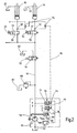
- the circuit arrangements shown each comprise a motor-operated hydraulic variable displacement pump 60, which can be adjusted via a pivotable adjusting element 58 and conveys hydraulic oil from a tank 62 into a feed line 64.
- the adjusting member 58 is adjustable via two actuating cylinders 66,68, one of which is spring-supported, continuously between two end positions corresponding to a minimum and a maximum flow rate V ⁇ min and V ⁇ max .
- the control of the actuating cylinder 66, 68 via a flow controller 70 and a parallel to this pressure regulator 72, which are each formed as a spring-centered 2/2-way valves 71,73.
- the directional control valves 71, 73 are acted upon on their one pilot control side by the pressure p at the pressure outlet of the variable displacement pump 60 and piloted on the opposite pilot control side by a respective adjusting spring 74, 76.
- the adjusting spring 74 of the flow control valve 70 is set to 18 bar, for example, while the compression spring 76 of the pressure regulator is set to 350 bar by way of example.
- On the spring side of the flow control valve 70 also a pilot line 78 is connected, which is acted upon in the operating state via the tap 92 with the highest load pressure p LS at the inputs of the loads 34,35, ....
- load-sensing regulator which tunes the displacement volume of the variable displacement pump 60 to the quantity required by the consumers 34, 35,...
- load-sensing controller is described below in the description of the operating state in connection with Fig. 2 and 3d explained in more detail.
- the feed line 64 is also the above-mentioned, designed as an optional mode valve reversing valve 54, which locks the feed line 64 in the stand-by state to the loads 34,35, ... and connects to the tank 62 and in the operating state to the Consumers 34,35, ... Deutschen tokent.
- Each consumer 34,35, ... is associated with a connected to the feed line 64 in parallel proportional valve 56 which, like the reversing valve 54 is controlled at its electromagnetic input 52,53 via the remote control device.
- the taps 92 for the load pressure signals are located respectively on the consumer side of the proportional valves 56.
- the shuttle valve chain 94 ensures that only the highest load pressure signal p LS is turned on to the pilot control line 78.
- variable displacement pump 60 In stand-by mode, the variable displacement pump 60 is always set to maximum flow rate via the delivery flow controller 70 in the absence of load pressure p LS and largely unpressurized state in the feed line 64.
- the guided over the reversing valve 54 to the tank 62 hydraulic oil is used in this case for system cooling. Nevertheless, it is considered disadvantageous that the variable displacement pump 60 is subject to a not inconsiderable power requirement for the circulation of the hydraulic oil in stand-by mode, which requires a correspondingly high fuel requirement.
- pilot control line 78 is guided via a shuttle valve 96 which is acted on the one hand via the Last réelleabgriffe 92 and the shuttle valve chain 94 with the currently highest load pressure p LS and on the other side via a switching valve 100th is connected to a pressure tap 102 in the feed line.
- the switching valve 100 is acted upon on the one hand via a prestressed spring 104 with a setting pressure of for example 100 bar, which is compared via the pilot control input 106 with the instantaneous load pressure p LS .
- the input module includes a switching valve 84, which controls in particular in the stand-by state between the feed line 64 and tank 62 and is otherwise locked.
- the switching valve 84 has a control input 86 acted upon via the tap 85 with the pressure p in the feed line 64 and an opposite pilot side 90 acted upon by a spring 88 and connected to the outlet of the throttle 80.
- the switching valve 84 in stand-by mode when the valves 54 and 56 are locked, ensures that the adjusting member 58 of the variable displacement pump 60 in a position with a minimum flow V ⁇ min is pivoted back. This is the case when the pressure built up via the spring 88 is greater than the pressure set via the adjusting spring 74 of the delivery flow regulator 70.
- the bias of the spring 88 can also be any intermediate positions of the flow to adjust the variable displacement 60 in the stand-by position. With these measures, the fuel consumption of the drive motor of the variable displacement pump 60 can be reduced in stand-by mode.
- the switching valve 100 ensures rapid pressure build-up on the selected consumers 34, 35, ....
- Fig. 3b shows the switching position, in which although the reversing valve 54 controlled by but no proportional valve 56 is still driven.
- the operating pressure p builds up very quickly behind the reversing valve 54, which is controlled via the pressure tap 102 and the switching valve 100 via the throttle 106 to an input of the shuttle valve 96. Since there is no load pressure p LS on the other side of the shuttle valve 96, the instantaneous pump pressure becomes p controlled by the flow regulator 70.
- variable displacement pump 60 initially operates as a pressure-controlled pump, so that prior to the proportional valve 56, a pressure up to that in the control group 107 via the pressure limiting valve 108 set pressure of 250 bar, for example.
- the switching valve 100 enters its closed position, so that the shuttle valve 96 is opened via the load pressure p LS in the line 98.
- the flow controller 70 is load pressure. This means that the delivery flow of the variable displacement pump 60 is dependent on the orifice 57 of the proportional valve 56 connected between the variable displacement pump 60 and the consumer 34, 35,.
- the additionally present pressure regulator 72 is superimposed on the delivery flow regulator 70, ie, below the set pressure setpoint at the pressure regulator 72 (eg 350 bar), the adjustment process in the variable displacement pump 60 is load pressure controlled.
- Another pressure limiting valve 110 ensures that the system pressure p in the feed line 64 does not exceed a predetermined maximum value of, for example, 380 bar.
- the circuit arrangement shown differs from the circuit arrangement Fig. 3a to d in that the switching valve 100 has an electromagnetic pilot input 106 ', which is actuated via a pressure switch 112 or pressure sensor 114 responding to the load pressure p LS .
- the pressure switch 112 or the pressure transducer 114 responds when the load pressure p LS a certain minimum pressure, z. B. 100 bar, exceeds.
- the spring 104 'on the switching valve 100 is in this case only a holding function.
- the invention relates to a hydraulic circuit arrangement, in particular for the drive of concrete distributor masts.
- the circuit arrangement comprises at least one on the input side via a feed line 64 to the pressure output of a hydraulic variable displacement pump 60 hydraulic consumers 34,35, ... and at least one arranged in the feed line 64, one of the consumers associated proportional valve 56, the feed line 64 in its rest position locks and forms an orifice 57 with a variable opening cross-section in an operating position.
- Next is in the feed line 64 in the stand-by state with the tank 62 and in the operating position with the at least one consumer 34,35, ... connected Um Tavernmaschine 82 is provided.
- the variable displacement pump 60 has an adjusting member 58, which is controlled via a flow divider 70 arranged in a pump branch 111, which comprises a directional control valve 71 whose one pilot control input is acted upon by the pump pressure p prevailing at the output of the variable displacement pump 60 and whose opposite pilot control input is defined Spring biased biasing force and in addition to the prevailing behind the orifice 57 load pressure p LS is acted upon.
- a responsive to the load pressure p LS control group 107 is provided with a switching valve 100 which below a predetermined minimum value of the load pressure p LS the adjusting member 58 of the variable 60 in its position for maximum Flow brings.
Landscapes
- Engineering & Computer Science (AREA)
- Mechanical Engineering (AREA)
- Physics & Mathematics (AREA)
- Fluid Mechanics (AREA)
- General Engineering & Computer Science (AREA)
- Architecture (AREA)
- Civil Engineering (AREA)
- Structural Engineering (AREA)
- Fluid-Pressure Circuits (AREA)
Claims (17)
- Circuit hydraulique, en particulier pour l'entraînement de mâts distributeurs de béton (14), avec au moins un consommateur hydraulique (34, 35, ...) relié côté entrée à la sortie de pression d'une pompe hydraulique à débit variable (60) par une conduite d'alimentation (64), avec au moins une vanne proportionnelle (56) disposée dans la conduite d'alimentation (64), associée chaque fois à un des consommateurs, qui ferme la conduite d'alimentation (64) dans sa position de repos et forme un orifice d'étranglement (57) à section d'ouverture variable dans sa position de fonctionnement, avec un groupe d'inversion (82) disposé dans la conduite d'alimentation (64), relié à un réservoir (62) dans la position de repos et audit au moins un consommateur (34, 35, ...) dans la position de fonctionnement, avec un organe de réglage (58) disposé dans la pompe à débit variable (60), qui est commandé par un régulateur de débit (70) disposé dans une branche de pompe, le régulateur de débit (70) comprenant un distributeur (71) dont une entrée de pilotage est soumise à la pression de pompe (p) régnant à la sortie de pression de la pompe à débit variable (60) et dont l'entrée de pilotage opposée est chargée par ressort à une force de précontrainte définie et en outre soumise à la pression de charge (pLS) régnant derrière l'orifice d'étranglement (57), caractérisé par un groupe de commande (107) réagissant à la pression de charge (pLS) qui, au-dessous d'une valeur minimale prédéfinie de la pression de charge, rend le distributeur (71) passant depuis le côté ressort et déplace ce faisant l'organe de réglage (58) de la pompe à débit variable (60) dans sa position permettant un débit maximal (Vmax).
- Circuit selon la revendication 1, caractérisé en ce que le groupe de commande (107) comporte une soupape de commutation (100) qui est précontrainte contre la pression d'un ressort de réglage (104) sous l'action de la pression de charge (pLS) et qui, lorsque la pression de charge (PLS) devient inférieure à la valeur minimale, fait passer la pression de pompe (p) du côté ressort du distributeur (71) du régulateur de débit (70).
- Circuit selon la revendication 2, caractérisé en ce que la soupape de commutation (100) est soumise directement à la pression de charge (PLS) à son entrée de pilotage opposée au ressort de réglage (104) et que la pression résultante réglée par le ressort de réglage (104) correspond à la valeur minimale de la pression de charge.
- Circuit selon la revendication 2, caractérisé en ce qu'un interrupteur à pression (112) ou un capteur de pression (114) soumis à la pression de charge (pLS), réagissant à la valeur minimale de la pression de charge, est prévu, et que l'entrée de pilotage de la soupape de commutation (100) opposée au ressort de réglage (104') est disposée dans le circuit de l'interrupteur à pression (112) ou du capteur de pression (114) et peut être actionnée électriquement et/ou magnétiquement par celui-ci.
- Circuit selon une des revendications 1 à 4, caractérisé en ce que le groupe de commande (107) est relié par un étranglement côté sortie (106) à l'entrée d'une soupape à deux voies (96) dont la deuxième entrée est soumise à la pression de charge (pLS) et dont la sortie est reliée au côté ressort du distributeur (71) du régulateur de débit (70).
- Circuit selon une des revendications 1 à 5, caractérisé en ce qu'une soupape de limitation de pression (108) disposée côté sortie, reliée au réservoir (62), est raccordée au groupe de commande (107).
- Circuit selon une des revendications 1 à 6, caractérisé en ce qu'une soupape de limitation de pression (110) reliée au réservoir (62) est disposée dans la conduite d'alimentation (64).
- Circuit selon une des revendications 1 à 7, caractérisé en ce qu'un régulateur de pression (72) placé en aval du régulateur de débit (70) et servant à commander l'organe de réglage (58) de la pompe à débit variable (60) est disposé en plus dans la branche de pompe (111).
- Circuit selon une des revendications 1 à 8, caractérisé en ce que l'organe de réglage (58) de la pompe à débit variable (60) est couplé à au moins un cylindre de réglage (66, 68) actionné par le régulateur de débit (70) et/ou le régulateur de pression (72).
- Circuit selon la revendication 9, caractérisé en ce que ledit au moins un cylindre de réglage est de préférence chargé par ressort dans la direction d'ouverture de l'organe de réglage (58).
- Circuit selon une des revendications 1 à 10, caractérisé en ce que plusieurs consommateurs (34, 35, ...) sont prévus, à chacun desquels est associée une vanne proportionnelle (56), et que les branches de charge des différents consommateurs (34, 35, ...) sont reliées au groupe de commande (107) et à sa soupape de commutation (100) par une chaîne de soupapes à deux voies (94) laissant passer le signal de pression de charge (PLS) le plus élevé.
- Circuit selon une des revendications 1 à 11, caractérisé en ce que le groupe d'inversion (82) comporte une soupape d'inversion (54) reliée par la conduite d'alimentation (64) au choix au consommateur (34, 35, ...) ou au réservoir (62), et qu'un étranglement (80) est disposé dans la conduite qui mène au réservoir (62).
- Circuit selon la revendication 12, caractérisé en ce que le groupe d'inversion (82) comporte un module d'entrée avec une soupape de commutation (84) assistée par ressort, qui est raccordée côté entrée à la conduite d'alimentation (64) et côté sortie au réservoir (62) et qui est pilotée de son côté ressort par la sortie de l'étranglement (80) et soumise du côté de pilotage opposé au ressort (88) à la pression de pompe (p).
- Circuit selon la revendication 13, caractérisé en ce que la pression hydraulique résultant de la force de ressort du ressort réglable (88) du module d'entrée est égale ou supérieure à la pression hydraulique résultant de la force de ressort du ressort de réglage (74) du régulateur de débit (70), de sorte que l'organe de réglage (58) de la pompe à débit variable (60) prend sa plus petite position d'ouverture (Vmin) ou sa position de fermeture dans la position d'attente du groupe d'inversion (82).
- Circuit selon la revendication 13, caractérisé en ce que la pression hydraulique résultant de la force de ressort du ressort réglable (88) du module d'entrée est plus petite que la pression hydraulique résultant de la force de ressort du ressort de réglage (74) du régulateur de débit (70) et dimensionnée de façon que l'organe de réglage (58) de la pompe à débit variable (60) prenne dans la position d'attente du groupe d'inversion (82) une position intermédiaire prédéfinie entre sa position d'ouverture la plus petite et la plus grande possible.
- Circuit hydraulique, en particulier pour l'entraînement de mâts distributeurs de béton (14), avec au moins un consommateur hydraulique (34, 35, ...) relié côté entrée à la sortie de pression d'une pompe hydraulique à débit variable (60) par une conduite d'alimentation (64), avec au moins une vanne proportionnelle (56) disposée dans la conduite d'alimentation (64), associée chaque fois à un des consommateurs (34, 35, ...), qui ferme la conduite d'alimentation (64) dans sa position de repos et forme un orifice d'étranglement (57) à section d'ouverture variable dans sa position de fonctionnement, avec un groupe d'inversion (82) disposé dans la conduite d'alimentation (64), relié à un réservoir (62) dans la position de repos et audit au moins un consommateur dans la position de fonctionnement, avec un organe de réglage (58) disposé dans la pompe à débit variable (60), qui est commandé par un régulateur de débit (70) disposé dans une branche de pompe, le régulateur de débit (70) comprenant un distributeur (71) dont une entrée de pilotage est soumise à la pression de pompe (p) régnant à la sortie de pression de la pompe à débit variable (60) et dont l'entrée de pilotage opposée est chargée par ressort à une force de précontrainte définie et en outre soumise à la pression de charge (PLS) régnant derrière l'orifice d'étranglement (57), caractérisé en ce que le groupe d'inversion (82) comporte une soupape de commutation (54) reliée par la conduite d'alimentation (64) au choix au consommateur (34, 35, ...) ou au réservoir (62), qu'un étranglement (80) est disposé dans la conduite menant au réservoir (62), que le groupe d'inversion (82) comporte un module d'entrée avec une soupape de commutation (84) assistée par ressort qui est raccordée côté entrée à la conduite d'alimentation (64) et côté sortie au réservoir (62) et qui est pilotée de son côté ressort par la sortie de l'étranglement (80) et soumise du côté de pilotage opposé au ressort (88) à la pression de pompe (p), et que la pression hydraulique résultant de la force de ressort du ressort réglable (88) du module d'entrée est égale ou supérieure à la pression hydraulique résultant de la force de ressort du ressort de réglage (74) du régulateur de débit (70), de sorte que l'organe de réglage (58) de la pompe à débit variable (60) prend sa plus petite position d'ouverture ou sa position de fermeture dans la position d'attente du groupe d'inversion (82).
- Circuit hydraulique, en particulier pour l'entraînement de mâts distributeurs de béton (14), avec au moins un consommateur hydraulique (34, 35, ...) relié côté entrée à la sortie de pression d'une pompe hydraulique à débit variable (60) par une conduite d'alimentation (64), avec au moins une vanne proportionnelle (56) disposée dans la conduite d'alimentation (64), associée chaque fois à un des consommateurs (34, 35, ...), qui ferme la conduite d'alimentation (64) dans sa position de repos et forme un orifice d'étranglement (52) à section d'ouverture variable dans sa position de fonctionnement, avec un groupe d'inversion (54, 82) disposé dans la conduite d'alimentation (64), relié à un réservoir (62) dans la position de repos et audit au moins un consommateur dans la position de fonctionnement, avec un organe de réglage (58) disposé dans la pompe à débit variable (60), qui est commandé par un régulateur de débit (70) disposé dans une branche de pompe, le régulateur de débit (70) comprenant un distributeur (71) dont une entrée de pilotage est soumise à la pression de pompe (p) régnant à la sortie de pression de la pompe à débit variable (60) et dont l'entrée de pilotage opposée est chargée par ressort à une force de précontrainte définie et en outre soumise à la pression de charge (PLS) régnant derrière l'orifice d'étranglement (57), caractérisé en ce que le groupe d'inversion (82) comporte une soupape de commutation (54) reliée par la conduite d'alimentation (64) au choix au consommateur (34, 35, ...) ou au réservoir (62), qu'un étranglement (80) est disposé dans la conduite menant au réservoir (62), que le groupe d'inversion (82) comporte un module d'entrée avec une soupape de commutation (84) assistée par ressort qui est raccordée côté entrée à la conduite d'alimentation (64) et côté sortie au réservoir (62) et qui est pilotée de son côté ressort par la sortie de l'étranglement (80) et soumise du côté de pilotage opposé au ressort (88) à la pression de pompe (p), et que la pression hydraulique résultant de la force de ressort du ressort réglable (88) du module d'entrée est plus petite que la pression hydraulique résultant de la force de ressort du ressort de réglage (74) du régulateur de débit (70) et dimensionnée de façon que l'organe de réglage (58) de la pompe à débit variable (60) prenne dans la position d'attente du groupe d'inversion (82) une position intermédiaire prédéfinie entre sa position d'ouverture la plus petite et la plus grande possible (Vmin, Vmax).
Applications Claiming Priority (2)
| Application Number | Priority Date | Filing Date | Title |
|---|---|---|---|
| DE102005035981A DE102005035981A1 (de) | 2005-07-28 | 2005-07-28 | Hydraulische Schaltungsanordnung, insbesondere für den Antrieb von Betonverteilermasten |
| PCT/EP2006/005043 WO2007012361A1 (fr) | 2005-07-28 | 2006-05-26 | Circuit hydraulique, en particulier pour l'entrainement de mats de distributeurs de beton |
Publications (2)
| Publication Number | Publication Date |
|---|---|
| EP1907706A1 EP1907706A1 (fr) | 2008-04-09 |
| EP1907706B1 true EP1907706B1 (fr) | 2014-04-30 |
Family
ID=37075820
Family Applications (1)
| Application Number | Title | Priority Date | Filing Date |
|---|---|---|---|
| EP06743070.2A Active EP1907706B1 (fr) | 2005-07-28 | 2006-05-26 | Circuit hydraulique, en particulier pour l'entraînement de mâts de distributeurs de béton |
Country Status (7)
| Country | Link |
|---|---|
| US (1) | US20080016862A1 (fr) |
| EP (1) | EP1907706B1 (fr) |
| JP (1) | JP2009503383A (fr) |
| KR (1) | KR20080038079A (fr) |
| CN (1) | CN101069018A (fr) |
| DE (1) | DE102005035981A1 (fr) |
| WO (1) | WO2007012361A1 (fr) |
Cited By (1)
| Publication number | Priority date | Publication date | Assignee | Title |
|---|---|---|---|---|
| EP3093505A1 (fr) | 2015-05-11 | 2016-11-16 | HAWE Hydraulik SE | Dispositif de commande hydraulique et sélecteur |
Families Citing this family (14)
| Publication number | Priority date | Publication date | Assignee | Title |
|---|---|---|---|---|
| DE102007055377A1 (de) * | 2007-11-19 | 2009-05-20 | Robert Bosch Gmbh | Hydraulische Steueranordnung und Wegeventilsektion |
| DE102011083874A1 (de) * | 2011-09-30 | 2013-04-04 | Putzmeister Engineering Gmbh | Hydrauliksystem mit Saug-Rücklauffilter |
| DE102012001369B4 (de) * | 2012-01-25 | 2021-12-16 | Robert Bosch Gmbh | Verstellbare Hydropumpe |
| DE102012207422A1 (de) * | 2012-05-04 | 2013-11-07 | Robert Bosch Gmbh | Hydraulische Steueranordnung mit Lastdruckminderungund hydraulischer Ventilblock dafür |
| DE102012209142A1 (de) | 2012-05-31 | 2013-12-05 | Putzmeister Engineering Gmbh | Hydrauliksystem |
| EP2679833B1 (fr) * | 2012-06-29 | 2018-03-21 | Fluid-System (Sarl) | Système hydraulique pour véhicule à détection de charge |
| DE102012216242A1 (de) * | 2012-09-13 | 2014-03-13 | Putzmeister Engineering Gmbh | Vorrichtung zur Antriebssteuerung einer Zweizylinder-Dickstoffpumpe |
| CN103031957B (zh) * | 2012-12-13 | 2014-02-19 | 北汽福田汽车股份有限公司 | 一种用于混凝土机械的控制系统及方法 |
| US20170328382A1 (en) * | 2016-05-13 | 2017-11-16 | Robert Bosch Gmbh | Hydraulic system for controlling an implement |
| DE102016122392A1 (de) * | 2016-11-21 | 2018-05-24 | Schwing Gmbh | Dickstoffpumpe mit einstellbarer Begrenzung des Förderdrucks |
| DE102018206271A1 (de) | 2018-04-24 | 2019-10-24 | Putzmeister Engineering Gmbh | Verfahren zur Bewegungssteuerung eines Masts und Arbeitsmaschine |
| DE102018109789A1 (de) | 2018-04-24 | 2019-10-24 | Putzmeister Engineering Gmbh | Verfahren und System zur hydraulischen Steuerung eines Betonverteilermasts |
| DE102018214965A1 (de) * | 2018-09-04 | 2020-03-05 | Putzmeister Engineering Gmbh | Autobetonpumpe |
| CN110118209B (zh) * | 2019-05-23 | 2023-10-20 | 福州大学 | 保证hb砼泵机稳定工作的换向控制回路系统 |
Family Cites Families (13)
| Publication number | Priority date | Publication date | Assignee | Title |
|---|---|---|---|---|
| US3973399A (en) * | 1975-12-29 | 1976-08-10 | Deere & Company | Demand compensated hydraulic system with pilot line dither |
| JPS5969505A (ja) * | 1982-10-14 | 1984-04-19 | Daikin Ind Ltd | キヤビテ−シヨン防止回路 |
| DE3340332C2 (de) * | 1983-11-08 | 1988-11-10 | Hydromatik GmbH, 7915 Elchingen | Leistungs-Regelvorrichtung für einen hydrostatischen Antrieb mit Fördermengeneinstellung |
| DE3607138C2 (de) * | 1986-03-05 | 1994-05-26 | Bosch Gmbh Robert | Hydraulikanlage mit einer Steuereinrichtung |
| US4798126A (en) * | 1987-03-23 | 1989-01-17 | Caterpillar Inc. | Load responsive system using load responsive pump control of a bypass type |
| DE3805287C2 (de) * | 1988-02-19 | 1995-02-09 | Rexroth Mannesmann Gmbh | Ventilanordnung für mindestens einen von einer Pumpe mit veränderlichem Fördervolumen gespeisten hydraulischen Verbraucher |
| DE3812753C2 (de) * | 1988-04-16 | 1994-05-26 | Rexroth Mannesmann Gmbh | Ventilanordnung für eine verstellbare Pumpe |
| DE4141492C2 (de) * | 1991-12-16 | 2000-08-10 | Mannesmann Rexroth Ag | Hydraulische Anordnung für Arbeitsmaschinen |
| DE4330137A1 (de) * | 1993-09-07 | 1995-03-09 | Putzmeister Maschf | Hydraulisches Druckversorgungs- und Steueraggregat für eine Autobetonpumpe |
| DE19517974A1 (de) * | 1995-05-16 | 1996-11-21 | Brueninghaus Hydromatik Gmbh | Verschiebbare hydraulische Leistungs- bzw. Momentenregeleinrichtung |
| DE10107107A1 (de) | 2001-02-14 | 2002-08-29 | Putzmeister Ag | Vorrichtung zur Betätigung eines Knickmasts eines Großmanipulators sowie Großmanipulator mit einer solchen Vorrichtung |
| DE10219850B3 (de) * | 2002-05-03 | 2004-02-05 | Brueninghaus Hydromatik Gmbh | Regeleinrichtung mit Grenzwertregelventil |
| US6874318B1 (en) * | 2003-09-18 | 2005-04-05 | Sauer-Danfoss, Inc. | Automatic remote pressure compensation in an open circuit pump |
-
2005
- 2005-07-28 DE DE102005035981A patent/DE102005035981A1/de not_active Withdrawn
-
2006
- 2006-05-26 EP EP06743070.2A patent/EP1907706B1/fr active Active
- 2006-05-26 KR KR1020077011574A patent/KR20080038079A/ko not_active Application Discontinuation
- 2006-05-26 CN CNA2006800012657A patent/CN101069018A/zh active Pending
- 2006-05-26 US US11/664,628 patent/US20080016862A1/en not_active Abandoned
- 2006-05-26 WO PCT/EP2006/005043 patent/WO2007012361A1/fr active Application Filing
- 2006-05-26 JP JP2008523144A patent/JP2009503383A/ja active Pending
Cited By (1)
| Publication number | Priority date | Publication date | Assignee | Title |
|---|---|---|---|---|
| EP3093505A1 (fr) | 2015-05-11 | 2016-11-16 | HAWE Hydraulik SE | Dispositif de commande hydraulique et sélecteur |
Also Published As
| Publication number | Publication date |
|---|---|
| CN101069018A (zh) | 2007-11-07 |
| WO2007012361A1 (fr) | 2007-02-01 |
| JP2009503383A (ja) | 2009-01-29 |
| KR20080038079A (ko) | 2008-05-02 |
| DE102005035981A1 (de) | 2007-02-01 |
| US20080016862A1 (en) | 2008-01-24 |
| EP1907706A1 (fr) | 2008-04-09 |
Similar Documents
| Publication | Publication Date | Title |
|---|---|---|
| EP1907706B1 (fr) | Circuit hydraulique, en particulier pour l'entraînement de mâts de distributeurs de béton | |
| EP1851445B1 (fr) | Entrainement hydraulique, notamment pour pompes a liquides epais a deux cylindres | |
| EP1915538B1 (fr) | Montage pour commander un cylindre d'entrainement hydraulique a double effet | |
| EP1355065B1 (fr) | Commande hydraulique | |
| EP2855945B2 (fr) | Méthode pour l'opération d'un système hydraulique | |
| WO2000000747A1 (fr) | Circuit hydraulique | |
| EP2895743B1 (fr) | Dispositif permettant de commander l'entraînement d'une pompe pour matières épaisses pourvue de deux cylindres | |
| WO1995032364A1 (fr) | Systeme de commande pour au moins deux consommateurs hydrauliques | |
| EP0670946A1 (fr) | Systeme hydraulique de commande et d'alimentation en pression pour pompe a beton pour chantier autoroutier | |
| EP0402390B1 (fr) | Agencement de commande de pompes a double cylindre pour liquides epais | |
| WO2008116451A1 (fr) | Ensemble de commande hydraulique | |
| EP2016818B1 (fr) | Dispositif de levage et procédé de commande d'un tel dispositif de levage | |
| EP2016817B1 (fr) | Procédé de commande d'un dispositif de levage et dispositif de levage | |
| DE3844405C2 (de) | Ventilanordnung für ein hydraulisches System | |
| DE19646427A1 (de) | Ventilanordnung | |
| DE19548943A1 (de) | Ventilanordnung | |
| WO1997028374A1 (fr) | Dispositif de commande hydraulique pour l'alimentation de plusieurs consommateurs hydrauliques en milieu de pression | |
| DE2800814A1 (de) | Hydraulische steuereinrichtung | |
| DE19719745B4 (de) | Druckschaltventilanordnung mit Überlastsicherungsfunktion für einen hydraulischen Verbraucher | |
| EP2674626B1 (fr) | Circuit hydraulique | |
| DE19749639A1 (de) | Hydraulische Schaltung | |
| EP2220383B1 (fr) | Dispositif de commande hydraulique | |
| DE102006060335B3 (de) | Hydraulische Ventilanordnung | |
| WO2002025118A2 (fr) | Procede et ensemble de commande pour commander des consommateurs hydrauliques | |
| DE3503374A1 (de) | Hydraulische ueberlastungsschutzvorrichtung fuer ein hebezeug |
Legal Events
| Date | Code | Title | Description |
|---|---|---|---|
| PUAI | Public reference made under article 153(3) epc to a published international application that has entered the european phase |
Free format text: ORIGINAL CODE: 0009012 |
|
| 17P | Request for examination filed |
Effective date: 20070216 |
|
| AK | Designated contracting states |
Kind code of ref document: A1 Designated state(s): AT BE BG CH CY CZ DE DK EE ES FI FR GB GR HU IE IS IT LI LT LU LV MC NL PL PT RO SE SI SK TR |
|
| RAP1 | Party data changed (applicant data changed or rights of an application transferred) |
Owner name: PUTZMEISTER ENGINEERING GMBH |
|
| DAX | Request for extension of the european patent (deleted) | ||
| RIC1 | Information provided on ipc code assigned before grant |
Ipc: F15B 11/16 20060101AFI20130925BHEP Ipc: F15B 11/05 20060101ALI20130925BHEP |
|
| GRAP | Despatch of communication of intention to grant a patent |
Free format text: ORIGINAL CODE: EPIDOSNIGR1 |
|
| INTG | Intention to grant announced |
Effective date: 20131213 |
|
| GRAS | Grant fee paid |
Free format text: ORIGINAL CODE: EPIDOSNIGR3 |
|
| GRAA | (expected) grant |
Free format text: ORIGINAL CODE: 0009210 |
|
| AK | Designated contracting states |
Kind code of ref document: B1 Designated state(s): AT BE BG CH CY CZ DE DK EE ES FI FR GB GR HU IE IS IT LI LT LU LV MC NL PL PT RO SE SI SK TR |
|
| REG | Reference to a national code |
Ref country code: GB Ref legal event code: FG4D Free format text: NOT ENGLISH Ref country code: CH Ref legal event code: EP |
|
| REG | Reference to a national code |
Ref country code: AT Ref legal event code: REF Ref document number: 665342 Country of ref document: AT Kind code of ref document: T Effective date: 20140515 |
|
| REG | Reference to a national code |
Ref country code: IE Ref legal event code: FG4D Free format text: LANGUAGE OF EP DOCUMENT: GERMAN |
|
| REG | Reference to a national code |
Ref country code: DE Ref legal event code: R096 Ref document number: 502006013701 Country of ref document: DE Effective date: 20140612 |
|
| REG | Reference to a national code |
Ref country code: LT Ref legal event code: MG4D |
|
| REG | Reference to a national code |
Ref country code: NL Ref legal event code: VDEP Effective date: 20140430 |
|
| PG25 | Lapsed in a contracting state [announced via postgrant information from national office to epo] |
Ref country code: FI Free format text: LAPSE BECAUSE OF FAILURE TO SUBMIT A TRANSLATION OF THE DESCRIPTION OR TO PAY THE FEE WITHIN THE PRESCRIBED TIME-LIMIT Effective date: 20140430 Ref country code: BG Free format text: LAPSE BECAUSE OF FAILURE TO SUBMIT A TRANSLATION OF THE DESCRIPTION OR TO PAY THE FEE WITHIN THE PRESCRIBED TIME-LIMIT Effective date: 20140730 Ref country code: LT Free format text: LAPSE BECAUSE OF FAILURE TO SUBMIT A TRANSLATION OF THE DESCRIPTION OR TO PAY THE FEE WITHIN THE PRESCRIBED TIME-LIMIT Effective date: 20140430 Ref country code: CY Free format text: LAPSE BECAUSE OF FAILURE TO SUBMIT A TRANSLATION OF THE DESCRIPTION OR TO PAY THE FEE WITHIN THE PRESCRIBED TIME-LIMIT Effective date: 20140430 Ref country code: NL Free format text: LAPSE BECAUSE OF FAILURE TO SUBMIT A TRANSLATION OF THE DESCRIPTION OR TO PAY THE FEE WITHIN THE PRESCRIBED TIME-LIMIT Effective date: 20140430 Ref country code: GR Free format text: LAPSE BECAUSE OF FAILURE TO SUBMIT A TRANSLATION OF THE DESCRIPTION OR TO PAY THE FEE WITHIN THE PRESCRIBED TIME-LIMIT Effective date: 20140731 Ref country code: IS Free format text: LAPSE BECAUSE OF FAILURE TO SUBMIT A TRANSLATION OF THE DESCRIPTION OR TO PAY THE FEE WITHIN THE PRESCRIBED TIME-LIMIT Effective date: 20140830 |
|
| PG25 | Lapsed in a contracting state [announced via postgrant information from national office to epo] |
Ref country code: PL Free format text: LAPSE BECAUSE OF FAILURE TO SUBMIT A TRANSLATION OF THE DESCRIPTION OR TO PAY THE FEE WITHIN THE PRESCRIBED TIME-LIMIT Effective date: 20140430 Ref country code: LV Free format text: LAPSE BECAUSE OF FAILURE TO SUBMIT A TRANSLATION OF THE DESCRIPTION OR TO PAY THE FEE WITHIN THE PRESCRIBED TIME-LIMIT Effective date: 20140430 Ref country code: ES Free format text: LAPSE BECAUSE OF FAILURE TO SUBMIT A TRANSLATION OF THE DESCRIPTION OR TO PAY THE FEE WITHIN THE PRESCRIBED TIME-LIMIT Effective date: 20140430 Ref country code: SE Free format text: LAPSE BECAUSE OF FAILURE TO SUBMIT A TRANSLATION OF THE DESCRIPTION OR TO PAY THE FEE WITHIN THE PRESCRIBED TIME-LIMIT Effective date: 20140430 |
|
| PG25 | Lapsed in a contracting state [announced via postgrant information from national office to epo] |
Ref country code: PT Free format text: LAPSE BECAUSE OF FAILURE TO SUBMIT A TRANSLATION OF THE DESCRIPTION OR TO PAY THE FEE WITHIN THE PRESCRIBED TIME-LIMIT Effective date: 20140901 |
|
| REG | Reference to a national code |
Ref country code: CH Ref legal event code: PL |
|
| PG25 | Lapsed in a contracting state [announced via postgrant information from national office to epo] |
Ref country code: RO Free format text: LAPSE BECAUSE OF FAILURE TO SUBMIT A TRANSLATION OF THE DESCRIPTION OR TO PAY THE FEE WITHIN THE PRESCRIBED TIME-LIMIT Effective date: 20140430 Ref country code: LI Free format text: LAPSE BECAUSE OF NON-PAYMENT OF DUE FEES Effective date: 20140531 Ref country code: DK Free format text: LAPSE BECAUSE OF FAILURE TO SUBMIT A TRANSLATION OF THE DESCRIPTION OR TO PAY THE FEE WITHIN THE PRESCRIBED TIME-LIMIT Effective date: 20140430 Ref country code: EE Free format text: LAPSE BECAUSE OF FAILURE TO SUBMIT A TRANSLATION OF THE DESCRIPTION OR TO PAY THE FEE WITHIN THE PRESCRIBED TIME-LIMIT Effective date: 20140430 Ref country code: SK Free format text: LAPSE BECAUSE OF FAILURE TO SUBMIT A TRANSLATION OF THE DESCRIPTION OR TO PAY THE FEE WITHIN THE PRESCRIBED TIME-LIMIT Effective date: 20140430 Ref country code: CZ Free format text: LAPSE BECAUSE OF FAILURE TO SUBMIT A TRANSLATION OF THE DESCRIPTION OR TO PAY THE FEE WITHIN THE PRESCRIBED TIME-LIMIT Effective date: 20140430 Ref country code: CH Free format text: LAPSE BECAUSE OF NON-PAYMENT OF DUE FEES Effective date: 20140531 Ref country code: MC Free format text: LAPSE BECAUSE OF FAILURE TO SUBMIT A TRANSLATION OF THE DESCRIPTION OR TO PAY THE FEE WITHIN THE PRESCRIBED TIME-LIMIT Effective date: 20140430 |
|
| REG | Reference to a national code |
Ref country code: DE Ref legal event code: R097 Ref document number: 502006013701 Country of ref document: DE |
|
| REG | Reference to a national code |
Ref country code: IE Ref legal event code: MM4A |
|
| PLBE | No opposition filed within time limit |
Free format text: ORIGINAL CODE: 0009261 |
|
| STAA | Information on the status of an ep patent application or granted ep patent |
Free format text: STATUS: NO OPPOSITION FILED WITHIN TIME LIMIT |
|
| GBPC | Gb: european patent ceased through non-payment of renewal fee |
Effective date: 20140730 |
|
| REG | Reference to a national code |
Ref country code: FR Ref legal event code: ST Effective date: 20150302 |
|
| 26N | No opposition filed |
Effective date: 20150202 |
|
| PG25 | Lapsed in a contracting state [announced via postgrant information from national office to epo] |
Ref country code: IE Free format text: LAPSE BECAUSE OF NON-PAYMENT OF DUE FEES Effective date: 20140526 |
|
| REG | Reference to a national code |
Ref country code: DE Ref legal event code: R097 Ref document number: 502006013701 Country of ref document: DE Effective date: 20150202 |
|
| PG25 | Lapsed in a contracting state [announced via postgrant information from national office to epo] |
Ref country code: FR Free format text: LAPSE BECAUSE OF NON-PAYMENT OF DUE FEES Effective date: 20140630 Ref country code: GB Free format text: LAPSE BECAUSE OF NON-PAYMENT OF DUE FEES Effective date: 20140730 |
|
| REG | Reference to a national code |
Ref country code: AT Ref legal event code: MM01 Ref document number: 665342 Country of ref document: AT Kind code of ref document: T Effective date: 20140526 |
|
| PG25 | Lapsed in a contracting state [announced via postgrant information from national office to epo] |
Ref country code: SI Free format text: LAPSE BECAUSE OF FAILURE TO SUBMIT A TRANSLATION OF THE DESCRIPTION OR TO PAY THE FEE WITHIN THE PRESCRIBED TIME-LIMIT Effective date: 20140430 |
|
| PG25 | Lapsed in a contracting state [announced via postgrant information from national office to epo] |
Ref country code: AT Free format text: LAPSE BECAUSE OF NON-PAYMENT OF DUE FEES Effective date: 20140526 |
|
| PG25 | Lapsed in a contracting state [announced via postgrant information from national office to epo] |
Ref country code: BE Free format text: LAPSE BECAUSE OF FAILURE TO SUBMIT A TRANSLATION OF THE DESCRIPTION OR TO PAY THE FEE WITHIN THE PRESCRIBED TIME-LIMIT Effective date: 20140531 Ref country code: HU Free format text: LAPSE BECAUSE OF FAILURE TO SUBMIT A TRANSLATION OF THE DESCRIPTION OR TO PAY THE FEE WITHIN THE PRESCRIBED TIME-LIMIT; INVALID AB INITIO Effective date: 20060526 Ref country code: LU Free format text: LAPSE BECAUSE OF NON-PAYMENT OF DUE FEES Effective date: 20140526 |
|
| PGFP | Annual fee paid to national office [announced via postgrant information from national office to epo] |
Ref country code: DE Payment date: 20210522 Year of fee payment: 16 Ref country code: IT Payment date: 20210524 Year of fee payment: 16 |
|
| PGFP | Annual fee paid to national office [announced via postgrant information from national office to epo] |
Ref country code: TR Payment date: 20210521 Year of fee payment: 16 |
|
| REG | Reference to a national code |
Ref country code: DE Ref legal event code: R119 Ref document number: 502006013701 Country of ref document: DE |
|
| PG25 | Lapsed in a contracting state [announced via postgrant information from national office to epo] |
Ref country code: DE Free format text: LAPSE BECAUSE OF NON-PAYMENT OF DUE FEES Effective date: 20221201 |
|
| PG25 | Lapsed in a contracting state [announced via postgrant information from national office to epo] |
Ref country code: IT Free format text: LAPSE BECAUSE OF NON-PAYMENT OF DUE FEES Effective date: 20220526 |