EP1906554A2 - Drahtlose Kommunikationsvorrichtung - Google Patents
Drahtlose Kommunikationsvorrichtung Download PDFInfo
- Publication number
- EP1906554A2 EP1906554A2 EP07101451A EP07101451A EP1906554A2 EP 1906554 A2 EP1906554 A2 EP 1906554A2 EP 07101451 A EP07101451 A EP 07101451A EP 07101451 A EP07101451 A EP 07101451A EP 1906554 A2 EP1906554 A2 EP 1906554A2
- Authority
- EP
- European Patent Office
- Prior art keywords
- phase difference
- wireless communication
- antennas
- phase
- communication device
- Prior art date
- Legal status (The legal status is an assumption and is not a legal conclusion. Google has not performed a legal analysis and makes no representation as to the accuracy of the status listed.)
- Granted
Links
Images




Classifications
-
- H—ELECTRICITY
- H04—ELECTRIC COMMUNICATION TECHNIQUE
- H04B—TRANSMISSION
- H04B7/00—Radio transmission systems, i.e. using radiation field
- H04B7/02—Diversity systems; Multi-antenna system, i.e. transmission or reception using multiple antennas
- H04B7/04—Diversity systems; Multi-antenna system, i.e. transmission or reception using multiple antennas using two or more spaced independent antennas
- H04B7/08—Diversity systems; Multi-antenna system, i.e. transmission or reception using multiple antennas using two or more spaced independent antennas at the receiving station
- H04B7/0837—Diversity systems; Multi-antenna system, i.e. transmission or reception using multiple antennas using two or more spaced independent antennas at the receiving station using pre-detection combining
- H04B7/0842—Weighted combining
- H04B7/086—Weighted combining using weights depending on external parameters, e.g. direction of arrival [DOA], predetermined weights or beamforming
-
- G—PHYSICS
- G01—MEASURING; TESTING
- G01S—RADIO DIRECTION-FINDING; RADIO NAVIGATION; DETERMINING DISTANCE OR VELOCITY BY USE OF RADIO WAVES; LOCATING OR PRESENCE-DETECTING BY USE OF THE REFLECTION OR RERADIATION OF RADIO WAVES; ANALOGOUS ARRANGEMENTS USING OTHER WAVES
- G01S3/00—Direction-finders for determining the direction from which infrasonic, sonic, ultrasonic or electromagnetic waves, or particle emission, not having a directional significance, are being received
- G01S3/02—Direction-finders for determining the direction from which infrasonic, sonic, ultrasonic or electromagnetic waves, or particle emission, not having a directional significance, are being received using radio waves
- G01S3/14—Systems for determining direction or deviation from predetermined direction
- G01S3/46—Systems for determining direction or deviation from predetermined direction using antennas spaced apart and measuring phase or time difference between signals therefrom, i.e. path-difference systems
-
- H—ELECTRICITY
- H01—ELECTRIC ELEMENTS
- H01Q—ANTENNAS, i.e. RADIO AERIALS
- H01Q3/00—Arrangements for changing or varying the orientation or the shape of the directional pattern of the waves radiated from an antenna or antenna system
- H01Q3/26—Arrangements for changing or varying the orientation or the shape of the directional pattern of the waves radiated from an antenna or antenna system varying the relative phase or relative amplitude of energisation between two or more active radiating elements; varying the distribution of energy across a radiating aperture
- H01Q3/267—Phased-array testing or checking devices
-
- H—ELECTRICITY
- H04—ELECTRIC COMMUNICATION TECHNIQUE
- H04B—TRANSMISSION
- H04B17/00—Monitoring; Testing
- H04B17/20—Monitoring; Testing of receivers
- H04B17/21—Monitoring; Testing of receivers for calibration; for correcting measurements
- H04B17/22—Monitoring; Testing of receivers for calibration; for correcting measurements for calibration of the receiver components
- H04B17/221—Monitoring; Testing of receivers for calibration; for correcting measurements for calibration of the receiver components of receiver antennas, e.g. as to amplitude or phase
Definitions
- the present invention relates to wireless communication devices, and more particularly, to a wireless communication device using an adaptive array antenna to perform wireless communication.
- an adaptive array antenna system has been introduced in anticipation of increase in the subscriber capacity or expansion of the cell radius.
- the adaptive array antenna system is a system wherein a plurality of antennas are arrayed so that their directivities can be dynamically varied in response to changes in the electromagnetic environment.
- FIG. 7 illustrates a schematic configuration of an adaptive array antenna system.
- the illustrated adaptive array antenna system is a model showing a basic receiving operation thereof and only the elements necessary for explaining the system are shown in the figure.
- the adaptive array antenna system 10 includes antenna branches 10-1 to 10-4 and a data demodulator 1c.
- the antenna branches 10-1 to 10-4 respectively comprise antennas 1-1 to 1-4, analog amplifiers 10b-1 to 10b-4, and A/D converters 10c-1 to 10c-4.
- the data demodulator 1c comprises multipliers 11-1 to 11-4, an adder 12, and a weighting factor setting unit 1c-1.
- the antennas 1-1 to 1-4 receive radio signals, which are then amplified by the analog amplifiers 10b-1 to 10b-4, respectively, and the A/D converters 10c-1 to 10c-4 convert the respective amplified analog signals to digital signals d1 to d4 (other elements in the individual branches, such as frequency converters, are omitted from the figure).
- the weighting factor setting unit 1c-1 determines weighting factors in accordance with setting information A, and the multipliers 11-1 to 11-4 respectively multiply the output signals d1 to d4 from the A/D converters 10c-1 to 10c-4 by the weighting factors W1 to W4 set by the weighting factor setting unit 1c-1.
- the adder 12 adds up the four weighted signals and outputs the resulting signal.
- the antennas 1-1 to 1-4 receive a radio signal with an arrival angle ⁇ .
- the antennas 1-2 to 1-4 receive the radio signal with phase differences ⁇ , 2 ⁇ , and 3 ⁇ , respectively, because of path differences (the phase difference between adjacent antennas is ⁇ ).
- the weighting factor setting unit 1c-1 For the multiplier 11-2 connected to the antenna 1-2, the weighting factor setting unit 1c-1 generates a weighting factor W2 for rotating the phase by ⁇ and sends the factor W2 to the multiplier 11-2, so that the multiplier 11-2 multiplies the signal d2 by the weighting factor W2 to correct the phase difference ⁇ . Also, for the multiplier 11-3 connected to the antenna 1-3, the weighting factor setting unit 1c-1 generates a weighting factor W3 for rotating the phase by 2 ⁇ and sends the factor W3 to the multiplier 11-3. Thus, the multiplier 11-3 multiplies the signal d3 by the weighting factor W3 to correct the phase difference 2 ⁇ .
- the weighting factor setting unit 1c-1 generates a weighting factor W4 for rotating the phase by 3 ⁇ and sends the factor W4 to the multiplier 11-4, whereupon the multiplier 11-4 multiplies the signal d4 by the weighting factor W4 to correct the phase difference 3 ⁇ .
- the multiplications using the respective weighting factors make it possible to cancel out all phase differences ⁇ between the antennas 1-1 to 1-4, allowing the multipliers 11-1 to 11-4 to output signals which are in phase with each other.
- the adder 12 adds up the in-phase signals, so that signal reception with high gain can be performed.
- the radio signal After reaching the antennas 1-1 to 1-4, the radio signal is subjected to analog amplification, A/D conversion, etc., as mentioned above.
- Nonlinear circuit elements for performing these functions have individually different characteristics, and the characteristics also vary in response to changes in temperature or other environmental conditions as well as with the lapse of time. Therefore, the phase characteristics (phase rotations) of the antenna branches 10-1 to 10-4 are not exactly the same but differ from one to another.
- the antenna branches 10-1 to 10-4 involve their own phase shifts, and if these phase shifts are not removed, the phase differences cannot be completely canceled out, making it impossible to perform the in-phase addition with accuracy.
- calibrator corrects the phase shifts of the individual antenna branches, whereby the antenna outputs can be weighted with accuracy in the data demodulator 1c.
- beamforming is carried out with the beam directivity of the array antenna adaptively controlled such that a narrow beam is directed to a desired station for communication.
- the base station When signal is transmitted from a base station equipped with an adaptive array antenna to a terminal, the base station carries out DL (Down Link) beamforming in such a manner that the beam directivity is highest in the DoA (Direction of Arrival) which is estimated from the UL (Up Link) signal transmitted from the terminal.
- DL Down Link
- a circuit for estimating the arrival direction (arrival angle) at the time of DL beamforming is called adaptive array searcher.
- adaptive array antenna systems are provided with the calibrator function and the adaptive array searcher function.
- the calibrator circuit and the adaptive array searcher circuit are mounted separately, though they include equivalent functional blocks that can be shared, and the equivalent circuit elements are operated at the same time, giving rise to the problem that the scale of the circuitry as well as the power consumption increase.
- the present invention was created in view of the above circumstances, and an object thereof is to provide a wireless communication device in which functional blocks common to both of a calibrator and an adaptive array searcher are shared by the two, thus permitting reduction in the scale of circuitry as well as in the power consumption.
- a wireless communication device using an adaptive array antenna to perform wireless communication comprises an array of antennas, and an adaptive array searcher for detecting a phase difference between the antennas and estimating a direction of arrival of received radio waves, wherein the adaptive array searcher shares part of circuitry with a calibrator which performs calibration by correcting a phase difference caused between antenna channels in the wireless communication device.
- FIG. 1 illustrates the principle of a wireless communication device.
- the wireless communication device 1 comprises an array of antennas 1-1 to 1-n, an adaptive array searcher 1a, and a data demodulator 1c.
- the adaptive array searcher 1a detects the phase difference between the antennas 1-1 to 1-n and estimates the direction of arrival of received radio waves.
- the data demodulator 1c includes a weighting factor setting unit 1c-1.
- the weighting factor setting unit 1c-1 sets weighting factors for weighting the outputs of the respective antennas 1-1 to 1-n so that the data demodulator 1c can demodulate received data (user data) received by the antennas 1-1 to 1-n.
- the adaptive array searcher 1a shares part of circuitry with a calibrator 1b which performs calibration by correcting the phase difference caused between antenna channels (identical in meaning to the aforementioned antenna branches) in the wireless communication device.
- the adaptive array searcher 1a has a calibration function incorporated therein (details of the circuit configuration will be described later with reference to FIG. 4).
- FIG. 2 shows the circuit configuration of the calibrator and its peripheral elements.
- the calibrator 3 is connected with a reference signal coupler 20 through receivers 23-1 to 23-4.
- the reference signal coupler 20 comprises a reference signal distributor (power divider) 21 and directional couplers 22-1 to 22-4.
- the calibrator 3 comprises a reference signal generator 31, multipliers 32-1 to 32-4, matched filters 33a to 33d, a combiner 34, multipliers 35a to 35c, a calibration timing calculator 36, a synchronization timing determiner 37, a buffer 38, and an averaging unit 39.
- the reference signal generator 31 outputs a reference signal which is used as a basis for performing calibration.
- a spread signal PN (Pseudo Noise) code
- the reference signal distributor 21 divides the power of the received reference signal into four reference signals, which are sent to the respective directional couplers 22-1 to 22-4.
- the directional coupler 22-1 allows the reference signal to be introduced to a line L1 connected to the antenna 1-1 and outputs the reference signal to the receiver 23-1.
- the directional couplers 22-2 to 22-4 allow the reference signals to enter lines L2 to L4 connected to the antennas 1-2 to 1-4, respectively, and output the reference signals to the respective receivers 23-2 to 23-4.
- the reference signal input to each of the directional couplers 22-1 to 22-4 is a spread signal and, therefore, is only a very small noise for the radio signal received by the antennas 1-1 to 1-4. Accordingly, the reference signal, if coupled with the radio signal from the antennas 1-1 to 1-4 by the directional couplers 22-1 to 22-4, does not affect the subsequent process, permitting calibration to be performed during the operation.
- the receivers 23-1 to 23-4 receive the reference signals and send the received signals to the respective multipliers 32-1 to 32-4.
- the output signal from each of the multipliers 32-1 to 32-4 is split into two, one being sent to the adaptive array searcher shown in FIG. 3 and the other to a corresponding one of the matched filters 33a to 33d.
- the matched filters 33a to 33d acquire synchronization between the reference signals of the respective antenna channels and the known reference signal pattern, and output demodulated signals (reference signal delay profiles) a1 to a4, respectively.
- the combiner 34 combines the demodulated signals a1 to a4 and provides a composite signal as its output.
- the calibration timing calculator 36 calculates a timing (corresponding to despreading timing for the reference signal) at which the power of the composite signal is highest (at its peak) within a fixed interval.
- the synchronization timing determiner 37 When supplied with the timing calculated by the calibration timing calculator 36, the synchronization timing determiner 37 generates a calibration timing signal tc for determining the reference signal with a timing that has the highest peak among the reference signal delay profiles, and sends the signal tc to the matched filters 33a to 33d for the purpose of symbol synchronization of the reference signals.
- the multiplier 35a multiplies the demodulated signals a1 and a2 together to obtain a product signal m2 indicative of a phase difference between the phase characteristics of the channels of the antennas 1-1 and 1-2, and sends the signal m2 to the buffer 38.
- the multiplier 35b multiplies the demodulated signals a2 and a3 together to obtain a product signal m3 indicative of a phase difference between the phase characteristics of the channels of the antennas 1-2 and 1-3, and sends the signal m3 to the buffer 38.
- the multiplier 35c multiplies the demodulated signals a3 and a4 together to obtain a product signal m4 indicative of a phase difference between the phase characteristics of the channels of the antennas 1-3 and 1-4, and sends the signal m4 to the buffer 38.
- the averaging unit 39 averages the product signals m2 to m4 supplied thereto via the buffer 38, and generates weighting factors wc2 to wc4 for calibration.
- the weighting factors wc2, wc3 and wc4 are sent to the multipliers 32-2, 32-3 and 32-4, respectively.
- the multiplier 32-2 multiplies the user data by the weighting factor wc2, to correct the phase difference caused by the circuit elements in the channel of the antenna 1-2.
- the multiplier 32-3 multiplies the user data by the weighting factor wc3, to correct the phase difference caused by the circuit elements in the channel of the antenna 1-3.
- the multiplier 32-4 multiplies the user data by the weighting factor wc4, to correct the phase difference caused by the circuit elements in the channel of the antenna 1-4.
- the phase of the antenna channel 1-1 is used as a reference phase. Specifically, the phases of the antennas 1-2 to 1-4 are made to coincide with that of the antenna 1-1, to thereby remove the phase difference between the antenna channels. Accordingly, the multiplier 32-1 is not applied with a weighting factor wc1 for phase difference correction (no phase rotation is given with respect to the antenna 1-1).
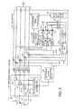
- FIG. 3 shows the circuit configuration of the adaptive array searcher.
- the adaptive array searcher 4 comprises matched filters 4-1 to 4-4, a timing calculation controller 40, a DoA (Direction of Arrival) calculator 50, and a demodulator interface 60.
- DoA Direction of Arrival
- the timing calculation controller 40 includes a buffer 41, multipliers 42-1 to 42-4, an in-phase combiner 43, and a timing calculator 44.
- the DoA calculator 50 includes multipliers 51a to 51c, an in-phase combiner 52, a DoA information generator 53, a DoA profile memory 54, a DoA/weighting factor converter 55, and a DoA information selector 56.
- the adaptive array searcher 4 is supplied with the user data of which the phase difference between the antenna channels has been canceled out by the preceding calibrator 3; therefore, the adaptive array searcher 4 may simply estimate the DoA based on the phase difference actually caused between the antennas.
- the phase difference between the antennas has only to be detected (in FIG. 7, for example, detecting the phase difference ⁇ between the antennas is equivalent to estimating the arrival direction (arrival angle ⁇ )).
- the matched filters 4-1 to 4-4 calculate instantaneous values of user data delay profiles, to generate user data-demodulated signals b1 to b4.
- the demodulated signals b1 to b4 are each split into two, one being sent to the buffer 41 in the timing calculation controller 40 and the other being sent to a corresponding one of the multipliers 51a to 51c in the DoA calculator 50.
- the multiplier 51a multiplies the demodulated signals b1 and b2 together and outputs the phase difference ⁇ 1 between the antennas 1-1 and 1-2.
- the multiplier 51b multiplies the demodulated signals b2 and b3 together and outputs the phase difference ⁇ 2 between the antennas 1-2 and 1-3.
- the multiplier 51c multiplies the demodulated signals b3 and b4 together and outputs the phase difference ⁇ 3 between the antennas 1-3 and 1-4.
- the in-phase combiner 52 combines the phase differences ⁇ 1 to ⁇ 3 in phase with each other and outputs a single phase difference signal.
- the three phase differences ⁇ 1 to ⁇ 3 between adjacent antennas ideally assume the same value ⁇ . In practice, however, the phase differences involve error because of noise or the like, and therefore, the phase differences are combined by the in-phase combiner 52 into a single phase difference signal.
- the DoA information generator 53 averages n phase difference signals ( ⁇ 1 to ⁇ n ) derived in one symbol interval, to generate DoA information corresponding to one symbol of the received data.
- the DoA profile memory 54 stores the DoA information.
- the DoA/weighting factor converter 55 converts the DoA information to weighting factors.
- the buffer 41 stores the demodulated signals b1 to b4 demodulated by the matched filters 4-1 to 4-4.
- the demodulated signals b1 to b4 are read from the buffer 41 after the DoA information corresponding to the demodulated signals b1 to b4 is created and then stored in the DoA profile memory 54.
- the multipliers 42-1 to 42-4 respectively multiply the signals output from the buffer 41 by the weighting factors received from the DoA/weighting factor converter 55 and output the resulting product signals.
- the in-phase combiner 43 combines the product signals in phase with each other and outputs a composite signal.
- the timing calculator 44 detects the timing (corresponding to despreading timing for the user data) at which the power of the composite signal is at its peak, and supplies the resulting user data timing signal td to the demodulator interface 60 and the DoA information selector 56.
- the DoA information selector 56 selects DoA information matching the timing of the user data timing signal td, from among the DoA information received from the DoA profile memory 54, and sends the selected DoA information D1 to the demodulator interface 60.
- the demodulator interface 60 On receiving the user data timing signal td and the selected DoA information D1 (more specifically, information showing the phase difference ⁇ between the antennas), the demodulator interface 60 sends the signal td and the information D1 to the succeeding data demodulator 1c shown in FIG. 1. Since the user data timing signal td shows the despreading timing for the user data, the data demodulator 1c can demodulate the received user data at that timing. Also, the weighting factor setting unit 1c-1 can calculate weighting factors based on the selected DoA information D1 ( ⁇ ).
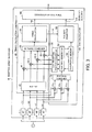
- FIG. 4 shows the circuit configuration of the wireless communication device 1.
- the wireless communication device 1 includes antennas 1-1 to 1-4, a reference signal coupler 20, receivers 23-1 to 23-4, an adaptive array searcher 1a, and a data demodulator 1c.
- the adaptive array searcher 1a comprises a reference signal generator 31, matched filters c0-1 to c0-4, multipliers 32-1 to 32-4, a timing calculation controller 40, a DoA calculator 50, a demodulator interface 60, a selector 70, a synchronization controller 71, and a calibration controller 1b-1.
- the timing calculation controller 40 is made up of a buffer 41, multipliers 42-1 to 42-4, an in-phase combiner c2, and a timing calculator c3.
- the DoA calculator 50 is constituted by multipliers c1-1 to c1-3, an in-phase combiner 52, a DoA information generator 53, a DoA profile memory 54, a DoA/weighting factor converter 55, and a DoA information selector 56.
- the calibration controller 1b-1 comprises a calibration weight information generator 3a, a buffer 38, and an averaging unit 39.
- Main circuit blocks that are shared by the calibrator 3 shown in FIG. 2 and the adaptive array searcher 4 shown in FIG. 3 are the matched filters c0-1 to c0-4, the multipliers c1-1 to c1-3 (phase difference detector), the in-phase combiner c2, and the timing calculator c3.
- the reference signal generator 31 outputs a reference signal (spread signal) which is used as a basis for performing the calibration.
- the reference signal coupler 20 divides the power of the received reference signal into four reference signals corresponding in number to the antennas 1-1 to 1-4, and causes the reference signals to enter respective lines L1 to L4 by means of directional couplers included therein.
- the receivers 23-1 to 23-4 receive the reference signals and send the received signals to the matched filters c0-1 to c0-4, respectively.
- the matched filters c0-1 to c0-4 acquire synchronization between the reference signals of the respective antenna channels and the known reference signal pattern, to generate demodulated reference signals (reference signal delay profiles), which are sent to the respective multipliers 32-1 to 32-4.
- the output signals from the multipliers 32-1 to 32-4 are each split into two, one being sent to the buffer 41 of the timing calculation controller 40 and the other being sent to a corresponding one of the multipliers c1-1 to c1-3 in the DoA calculator 50.
- the signals output to the buffer 41 from the multipliers 32-1 to 32-4 are then sent via the multipliers 42-1 to 42-4 to the in-phase combiner c2.
- the in-phase combiner c2 combines the demodulated reference signals and outputs the resulting composite signal.
- the timing calculator c3 When supplied with the composite signal, the timing calculator c3 calculates the timing (corresponding to despreading timing for the reference signal) at which the power of the composite signal is highest (at its peak) in a fixed interval, and sends the resulting reference timing signal tc to the calibration weight information generator 3a.
- the multiplier c1-1 multiplies the demodulated reference signals output from the multipliers 32-1 and 32-2, and sends the resulting product signal, which indicates the phase difference between the phase characteristic of the channels of the antennas 1-1 and 1-2, to the buffer 38.
- the multiplier c1-2 multiplies the demodulated reference signals output from the multipliers 32-2 and 32-3, and sends the resulting product signal, which indicates the phase difference between the phase characteristics of the channels of the antennas 1-2 and 1-3, to the buffer 38.
- the multiplier c1-3 multiplies the demodulated reference signals output from the multipliers 32-3 and 32-4, and sends the resulting product signal, which indicates the phase difference between the phase characteristics of the channels of the antennas 1-3 and 1-4, to the buffer 38.
- the calibration weight information generator 3a In response to the reference timing signal tc output from the timing calculator c3, the calibration weight information generator 3a generates calibration weight information (calibration weighting factor Wc) on the basis of the received product signals, and sends the generated information to the DoA information selector 56. Also, in response to the reference timing signal tc, the calibration weight information generator 3a sends the product signals received from the buffer 38 to the averaging unit 39.
- the averaging unit 39 averages the product signals and generates calibration weighting factors wc2 to wc4.
- the weighting factor wc2 is sent to the multiplier 32-2, the weighting factor wc3 to the multiplier 32-3, and the weighting factor wc4 to the multiplier 32-4.
- the multiplier 32-2 multiplies the user data by the weighting factor wc2 to correct the phase difference caused by the circuit elements in the channel of the antenna 1-2.
- the multiplier 32-3 multiplies the user data by the weighting factor wc3 to correct the phase difference caused by the circuit elements in the channel of the antenna 1-3.
- the multiplier 32-4 multiplies the user data by the weighting factor wc4 to correct the phase difference caused by the circuit elements in the channel of the antenna 1-4.
- the phase of the antenna channel 1-1 is used as a reference phase. Specifically, the phases of the antenna channels 1-2 to 1-4 are made to coincide with that of the antenna channel 1-1, to thereby remove the phase difference between the antenna channels. Accordingly, the multiplier 32-1 is not applied with a weighting factor for phase difference correction.
- the receivers 23-1 to 23-4 subject the radio signals received by the antennas 1-1 to 1-4 to amplification, down-conversion, etc., and supply the resulting signals to the respective matched filters c0-1 to c0-4 as user data.
- the matched filters c0-1 to c0-4 calculate instantaneous values of user data delay profiles, to generate user data-demodulated signals (demodulated user signals):
- the demodulated user signals are sent to the respective multipliers 32-1 to 32-4 and are each split into two at the output stage of same, one being sent to the buffer 41 in the timing calculation controller 40 and the other being sent to a corresponding one of the multipliers c1-1 to c1-3 in the DoA calculator 50.
- the multiplier c1-1 multiplies the demodulated user signals output from the multipliers 32-1 and 32-2, and outputs the phase difference ⁇ 1 between the antennas 1-1 and 1-2.
- the multiplier c1-2 multiplies the demodulated user signals output from the multipliers 32-2 and 32-3, and outputs the phase difference ⁇ 2 between the antennas 1-2 and 1-3.
- the multiplier c1-3 multiplies the demodulated user signals output from the multipliers 32-3 and 32-4, and outputs the phase difference ⁇ 3 between the antennas 1-3 and 1-4.
- the in-phase combiner 52 combines the phase differences ⁇ 1 to ⁇ 3 in phase with each other and outputs a single phase difference signal.
- the three phase differences ⁇ 1 to ⁇ 3 ideally assume the same value ⁇ . In practice, however, the phase differences involve error because of noise or the like, and therefore, the phase differences are combined by the in-phase combiner 52 into a single phase difference signal.
- the DoA information generator 53 averages the phase difference signals derived in one symbol interval and generates multiple items of DoA information corresponding to one symbol interval of the received data.
- the DoA profile memory 54 stores the DoA information.
- the DoA/weighting factor converter 55 converts the DoA information to weighting factors.
- the buffer 41 stores the demodulated user signals demodulated by the matched filters c0-1 to c0-4.
- the demodulated user signals are output from the buffer 41 after the DoA information corresponding to the demodulated user signals is generated and then stored in the DoA profile memory 54.
- the synchronization controller 71 (which may be implemented by the synchronization timing determiner 37 of the calibrator 3) generates, in response to an external signal, not shown, transmitted thereto from a host, a synchronization timing signal t1 for switching operation between the calibration and the DoA estimation, and sends the generated signal t1 to the selector 70.
- the selector 70 On receiving the synchronization timing signal t1 from the synchronization controller 71, the selector 70 sends the weighting factors, received from the DoA/weighting factor converter 55, to the multipliers 42-1 to 42-4.
- the multipliers 42-1 to 42-4 respectively multiply the signals output from the buffer 41 by the weighting factors received from the DoA/weighting factor converter 55 via the selector 70, and output the resulting product signals.
- the in-phase combiner c2 combines the product signals in phase with each other and outputs a composite signal.
- the timing calculator c3 detects the timing (corresponding to despreading timing for the user data) at which the power of the composite signal is at its peak, and supplies the detected timing, as the user data timing signal td, to the demodulator interface 60 and the DoA information selector 56.
- the DoA information selector 56 selects DoA information matching the timing of the user data timing signal td, from among the DoA information received from the DoA profile memory 54, and sends the selected DoA information D1 to the demodulator interface 60.
- the demodulator interface 60 On receiving the user data timing signal td and the selected DoA information D1 (more specifically, information showing the phase difference ⁇ between the antennas), the demodulator interface 60 generates setting information A (the contents of the setting information A will be described later with reference to FIGS. 5 and 6), and sends the generated information A to the data demodulator 1c. Since the user data timing signal td shows the despreading timing for the user data, the data demodulator 1c can demodulate the received user data at that timing. Also, the weighting factor setting unit 1c-1 can calculate weighting factors based on the selected DoA information D1 ( ⁇ ).
- the data demodulator 1c also receives the user data (corresponding to the signals d1 to d4 in FIG. 7) output from the receivers 23-1 to 23-4.
- the weighting factor setting unit 1c-1 in the data demodulator 1c weights the user data, namely, the antenna outputs.
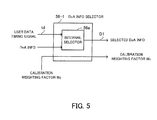
- the DoA information selector 56-1 includes an internal selector 56a.
- the internal selector 56a receives the user data timing signal (despreading timing information for the user data) td output from the timing calculator c3 as well as the DoA information output from the DoA profile memory 54, and sends the DoA information matching the timing of the user data timing signal td to the demodulator interface 60 as the selected DoA information D1.
- the DoA information selector receives the calibration weighting factor Wc output from the calibration weight information generator 3a and passes same through to the demodulator interface 60.
- the weighting factor setting unit 1c-1 in the data demodulator 1c calculates weighting factors W1 to W4 for correcting the phase difference between the antennas 1-1 to 1-4, as shown in FIG. 7, and sends the weighting factors W1 to W4 to the respective multipliers 11-1 to 11-4 to correct the phase difference between the antennas.
- FIG. 6 shows the configuration of another DoA information selector.
- the DoA information selector 56-2 includes an internal selector 56a and a multiplier 56b.
- the internal selector 56a receives the user data timing signal (despreading timing information for the user data) td output from the timing calculator c3 as well as the DoA information output from the DoA profile memory 54, and outputs, as the selected DoA information D1, the DoA information matching the timing of the user data timing signal.
- the multiplier 56b multiplies the selected DoA information D1 by the calibration weighting factor Wc output from the calibration weight information generator 3a to generate weighting factors W1 to W4 for correcting the post-calibration phase difference between the antennas, and sends the calculated weighting factors to the demodulator interface 60.
- the weighting factor setting unit 1c-1 in the data demodulator 1c sends the weighting factors W1 to W4 to the respective multipliers 11-1 to 11-4, as shown in FIG. 7, to correct the phase difference between the antennas 1-1 to 1-4.
- the wireless communication device may be configured such that up to the calculation of the weighting factors for correcting the phase difference between the antennas 1-1 to 1-4 is performed by the adaptive array searcher 1a and that only the calculation results are sent to the data demodulator 1c.
- the adaptive array searcher for estimating the direction of arrival of received radio waves shares part of circuitry with the calibrator for correcting the phase difference caused between the antenna channels in the wireless communication device and thus has a calibration function incorporated therein. Since the calibrator and the adaptive array searcher share equivalent functional blocks, the scale of the circuitry as well as the power consumption can be cut down.
Landscapes
- Engineering & Computer Science (AREA)
- Physics & Mathematics (AREA)
- Computer Networks & Wireless Communication (AREA)
- Signal Processing (AREA)
- Electromagnetism (AREA)
- General Physics & Mathematics (AREA)
- Radar, Positioning & Navigation (AREA)
- Remote Sensing (AREA)
- Radio Transmission System (AREA)
- Variable-Direction Aerials And Aerial Arrays (AREA)
- Mobile Radio Communication Systems (AREA)
Applications Claiming Priority (1)
| Application Number | Priority Date | Filing Date | Title |
|---|---|---|---|
| JP2006266178A JP5186748B2 (ja) | 2006-09-29 | 2006-09-29 | 無線通信装置および無線通信方法 |
Publications (3)
| Publication Number | Publication Date |
|---|---|
| EP1906554A2 true EP1906554A2 (de) | 2008-04-02 |
| EP1906554A3 EP1906554A3 (de) | 2009-06-17 |
| EP1906554B1 EP1906554B1 (de) | 2010-10-20 |
Family
ID=38736029
Family Applications (1)
| Application Number | Title | Priority Date | Filing Date |
|---|---|---|---|
| EP20070101451 Ceased EP1906554B1 (de) | 2006-09-29 | 2007-01-30 | Drahtlose Kommunikationsvorrichtung |
Country Status (5)
| Country | Link |
|---|---|
| US (1) | US8019285B2 (de) |
| EP (1) | EP1906554B1 (de) |
| JP (1) | JP5186748B2 (de) |
| CN (1) | CN101154979B (de) |
| DE (1) | DE602007009913D1 (de) |
Cited By (5)
| Publication number | Priority date | Publication date | Assignee | Title |
|---|---|---|---|---|
| EP2372929A3 (de) * | 2010-03-31 | 2012-05-23 | Ubidyne, Inc. | Aktive Antennenanordnung und Verfahren zur Kalibrierung von Empfangswegen in besagter Anordnung |
| US8311166B2 (en) | 2010-03-31 | 2012-11-13 | Ubidyne, Inc. | Active antenna array and method for calibration of the active antenna array |
| US8340612B2 (en) | 2010-03-31 | 2012-12-25 | Ubidyne, Inc. | Active antenna array and method for calibration of the active antenna array |
| CN101639533B (zh) * | 2008-07-28 | 2013-01-09 | 株式会社电装 | 具有非均匀间隔天线阵列的雷达 |
| EP3145093A4 (de) * | 2014-05-12 | 2017-12-20 | Mitsubishi Electric Corporation | Kalibrierungsvorrichtung |
Families Citing this family (24)
| Publication number | Priority date | Publication date | Assignee | Title |
|---|---|---|---|---|
| US7876864B2 (en) * | 2007-05-03 | 2011-01-25 | Motorola, Inc. | Method and device for enhancing signal detection in a frequency selective fading channel |
| KR20110091596A (ko) * | 2007-11-28 | 2011-08-11 | 한양대학교 산학협력단 | 에스디알 시스템을 위한 다중 안테나 시스템 |
| JP5146138B2 (ja) * | 2008-06-19 | 2013-02-20 | 富士通株式会社 | 無線通信装置および送信ビーム制御方法 |
| US8358716B2 (en) * | 2009-03-06 | 2013-01-22 | Massachusetts Institute Of Technology | Method and apparatus for synchronizing a wireless communication system |
| US8264406B2 (en) * | 2010-04-14 | 2012-09-11 | Motorola Mobility Llc | Manifold calibration for a communication system |
| WO2012047050A2 (ko) | 2010-10-06 | 2012-04-12 | 한양대학교 산학협력단 | 스마트안테나 소프트웨어 정의 라디오 단말 장치 및 소프트웨어 정의 라디오 단말 어플리케이션의 배포 및 설치 방법 |
| SG189297A1 (en) * | 2010-10-21 | 2013-05-31 | Locata Corp | Method and apparatus for forming a remote beam |
| JP5736545B2 (ja) * | 2011-08-02 | 2015-06-17 | パナソニックIpマネジメント株式会社 | フェイズドアレーアンテナのブランチ間補正装置及びフェイズドアレーアンテナのブランチ間補正方法 |
| CN103477570B (zh) | 2011-08-02 | 2016-04-27 | 松下电器产业株式会社 | 相控阵发送装置 |
| WO2013032452A1 (en) * | 2011-08-30 | 2013-03-07 | Intel Corporation | Device, system and method of combining received wireless communication signals |
| WO2014032235A1 (zh) * | 2012-08-29 | 2014-03-06 | 华为技术有限公司 | 模块化天线装置及其配置方法 |
| US8994581B1 (en) | 2012-09-25 | 2015-03-31 | Adam Brown | Direction of arrival (DOA) estimation using multiple offset receive channels |
| RU2540126C1 (ru) * | 2013-09-25 | 2015-02-10 | Федеральное государственное казенное военное образовательное учреждение высшего профессионального образования "Военный учебно-научный центр Военно-воздушных сил "Военно-воздушная академия имени профессора Н.Е. Жуковского и Ю.А. Гагарина" (г. Воронеж) Министерства обороны Российской Федерации | Способ пространственного мониторинга источников электромагнитного излучения |
| EP3066762B1 (de) * | 2013-11-08 | 2018-02-21 | Telefonaktiebolaget LM Ericsson (publ) | Funkeinheit mit interner paralleler antennenkalibrierung |
| RU2551355C1 (ru) * | 2013-12-30 | 2015-05-20 | Федеральное государственное бюджетное образовательное учреждение высшего профессионального образования "Московский государственный технический университет имени Н.Э. Баумана" (МГТУ им. Н.Э. Баумана) | Способ определения координат источника радиоизлучения |
| US10056685B2 (en) * | 2014-03-06 | 2018-08-21 | Samsung Electronics Co., Ltd. | Antenna array self-calibration |
| JP6264204B2 (ja) * | 2014-06-17 | 2018-01-24 | 富士通株式会社 | 通信装置及び位相調整方法 |
| CN107258074A (zh) * | 2014-12-19 | 2017-10-17 | 中兴通讯股份有限公司 | 高效输出功率合成的数字微波无线电系统 |
| JP2016167781A (ja) * | 2015-03-10 | 2016-09-15 | 富士通株式会社 | 無線通信装置及び無線通信装置の制御方法 |
| JP2017212594A (ja) * | 2016-05-25 | 2017-11-30 | 富士通株式会社 | 無線通信装置及びキャリブレーション方法 |
| US10775510B2 (en) * | 2016-06-06 | 2020-09-15 | Brian G. Agee | Blind despreading of civil GNSS signals for resilient PNT applications |
| US10914829B2 (en) * | 2017-01-27 | 2021-02-09 | Panasonic Intellectual Property Management Co., Ltd. | Positioning sensor, sensor, and method |
| WO2019046822A1 (en) * | 2017-08-31 | 2019-03-07 | Chaos Prime, Inc. | IMPLICIT TRANSFER CORRELATION TECHNIQUES FOR ARBITRATED WAVEFORM SPECTRUM WAVEFORMS |
| KR20220103559A (ko) | 2021-01-15 | 2022-07-22 | 삼성전자주식회사 | 무선 통신 시스템에서 오차를 보상하기 위한 장치 및 방법 |
Family Cites Families (33)
| Publication number | Priority date | Publication date | Assignee | Title |
|---|---|---|---|---|
| IL100213A (en) * | 1990-12-07 | 1995-03-30 | Qualcomm Inc | CDMA microcellular telephone system and distributed antenna system therefor |
| FI105515B (fi) * | 1995-05-24 | 2000-08-31 | Nokia Networks Oy | Menetelmä kanavanvaihdon nopeuttamiseksi sekä solukkoradiojärjestelmä |
| US6275543B1 (en) * | 1996-10-11 | 2001-08-14 | Arraycomm, Inc. | Method for reference signal generation in the presence of frequency offsets in a communications station with spatial processing |
| US20030186725A1 (en) * | 1997-03-18 | 2003-10-02 | Matsushita Electric Industrial Co., Ltd. | Calibration apparatus for array antenna radio receiving apparatus |
| EP0938204A4 (de) * | 1997-03-18 | 2005-01-26 | Matsushita Electric Industrial Co Ltd | Kalibrierungseinrichtung für gruppenantenne eines drahtlosen empfängers |
| JP3369466B2 (ja) * | 1997-03-18 | 2003-01-20 | 松下電器産業株式会社 | アレーアンテナ無線受信装置のキャリブレーション装置 |
| JPH10336149A (ja) * | 1997-05-28 | 1998-12-18 | Matsushita Electric Ind Co Ltd | アレーアンテナ無線cdma通信装置 |
| BR9812816A (pt) * | 1997-09-15 | 2000-08-08 | Adaptive Telecom Inc | Processos para comunicação sem fio, e para eficientemente determinar na estação base um canal espacial da unidade móvel em um sistema de comunicação sem fio, e, estação base de cdma |
| US6037898A (en) * | 1997-10-10 | 2000-03-14 | Arraycomm, Inc. | Method and apparatus for calibrating radio frequency base stations using antenna arrays |
| JPH11251959A (ja) * | 1998-03-05 | 1999-09-17 | Fujitsu Ltd | 干渉キャンセラ装置及び無線通信装置 |
| JP3406831B2 (ja) * | 1998-03-19 | 2003-05-19 | 富士通株式会社 | 無線基地局のアレーアンテナシステム |
| KR100381812B1 (ko) * | 1998-11-19 | 2003-04-30 | 니폰 덴신 덴와 가부시끼가이샤 | 적응 어레이 안테나 장치 |
| JP2000295152A (ja) * | 1999-04-01 | 2000-10-20 | Matsushita Electric Ind Co Ltd | アレーアンテナ無線通信装置 |
| JP3251261B2 (ja) * | 1999-04-21 | 2002-01-28 | エヌイーシーモバイリング株式会社 | Cdma受信装置 |
| US6236839B1 (en) * | 1999-09-10 | 2001-05-22 | Utstarcom, Inc. | Method and apparatus for calibrating a smart antenna array |
| GB2354403B (en) * | 1999-09-16 | 2004-02-11 | Ericsson Telefon Ab L M | Communication systems |
| US6370182B2 (en) * | 2000-02-10 | 2002-04-09 | Itt Manufacturing Enterprises, Inc. | Integrated beamforming/rake/mud CDMA receiver architecture |
| WO2001067627A1 (en) * | 2000-03-06 | 2001-09-13 | Fujitsu Limited | Cdma receiver and searcher of the cdma receiver |
| JP3520026B2 (ja) * | 2000-04-03 | 2004-04-19 | 三洋電機株式会社 | 無線基地局、その制御方法およびプログラム記録媒体 |
| JP3424659B2 (ja) * | 2000-06-02 | 2003-07-07 | 日本電気株式会社 | マルチビーム受信装置 |
| JP3580495B2 (ja) * | 2000-08-25 | 2004-10-20 | 日本電気株式会社 | 適応アンテナ受信装置 |
| US7062294B1 (en) * | 2000-09-29 | 2006-06-13 | Arraycomm, Llc. | Downlink transmission in a wireless data communication system having a base station with a smart antenna system |
| US7006797B1 (en) * | 2001-05-21 | 2006-02-28 | Counter Technologies, Llc | Coherence frequency determining system and associated radio apparatus |
| JP2003218621A (ja) * | 2002-01-21 | 2003-07-31 | Nec Corp | アレーアンテナの校正装置及び校正方法 |
| JP4086574B2 (ja) * | 2002-04-12 | 2008-05-14 | 松下電器産業株式会社 | パスサーチ回路、無線受信装置及び無線送信装置 |
| JP3895228B2 (ja) * | 2002-05-07 | 2007-03-22 | 松下電器産業株式会社 | 無線通信装置および到来方向推定方法 |
| JP3856126B2 (ja) * | 2002-05-21 | 2006-12-13 | 日本電気株式会社 | パスタイミング検出方法、パスタイミング検出装置及び適応アレーアンテナシステム |
| JP2003338804A (ja) * | 2002-05-22 | 2003-11-28 | Nec Corp | パスサーチ装置及び方法並びにそれを用いたアレイアンテナ受信装置 |
| US7558350B2 (en) * | 2003-03-04 | 2009-07-07 | Nec Corporation | Adaptive antenna reception device having excellent initial directional beam reception quality |
| US7308286B2 (en) * | 2003-11-20 | 2007-12-11 | Telefonaktiebolaget Lm Ericsson (Publ) | Multi-dimensional joint searcher and channel estimators |
| JP4329594B2 (ja) * | 2004-03-30 | 2009-09-09 | 富士通株式会社 | アレーアンテナ無線通信装置およびそのパスタイミング検出方法 |
| JP4524147B2 (ja) * | 2004-06-30 | 2010-08-11 | 京セラ株式会社 | 通信装置、キャリブレーション方法及びプログラム |
| JP4528208B2 (ja) * | 2005-06-10 | 2010-08-18 | 富士通株式会社 | アレイアンテナの校正装置及び校正方法 |
-
2006
- 2006-09-29 JP JP2006266178A patent/JP5186748B2/ja not_active Expired - Fee Related
-
2007
- 2007-01-30 EP EP20070101451 patent/EP1906554B1/de not_active Ceased
- 2007-01-30 DE DE200760009913 patent/DE602007009913D1/de active Active
- 2007-02-13 CN CN2007100791188A patent/CN101154979B/zh not_active Expired - Fee Related
- 2007-02-22 US US11/709,250 patent/US8019285B2/en not_active Expired - Fee Related
Cited By (6)
| Publication number | Priority date | Publication date | Assignee | Title |
|---|---|---|---|---|
| CN101639533B (zh) * | 2008-07-28 | 2013-01-09 | 株式会社电装 | 具有非均匀间隔天线阵列的雷达 |
| EP2372929A3 (de) * | 2010-03-31 | 2012-05-23 | Ubidyne, Inc. | Aktive Antennenanordnung und Verfahren zur Kalibrierung von Empfangswegen in besagter Anordnung |
| US8311166B2 (en) | 2010-03-31 | 2012-11-13 | Ubidyne, Inc. | Active antenna array and method for calibration of the active antenna array |
| US8340612B2 (en) | 2010-03-31 | 2012-12-25 | Ubidyne, Inc. | Active antenna array and method for calibration of the active antenna array |
| US8441966B2 (en) | 2010-03-31 | 2013-05-14 | Ubidyne Inc. | Active antenna array and method for calibration of receive paths in said array |
| EP3145093A4 (de) * | 2014-05-12 | 2017-12-20 | Mitsubishi Electric Corporation | Kalibrierungsvorrichtung |
Also Published As
| Publication number | Publication date |
|---|---|
| CN101154979A (zh) | 2008-04-02 |
| US20080079634A1 (en) | 2008-04-03 |
| CN101154979B (zh) | 2011-06-15 |
| DE602007009913D1 (de) | 2010-12-02 |
| EP1906554B1 (de) | 2010-10-20 |
| JP2008085926A (ja) | 2008-04-10 |
| JP5186748B2 (ja) | 2013-04-24 |
| EP1906554A3 (de) | 2009-06-17 |
| US8019285B2 (en) | 2011-09-13 |
Similar Documents
| Publication | Publication Date | Title |
|---|---|---|
| EP1906554A2 (de) | Drahtlose Kommunikationsvorrichtung | |
| CN100459469C (zh) | 具有自适应更新权重的自适应天线接收装置 | |
| US7340248B2 (en) | Calibration apparatus | |
| EP1361678B1 (de) | Dispositif de recherche de voie, récepteur et emetteur radio utilisant un dispositif d'antenne à faisceau directionnel | |
| US6064338A (en) | Array antenna system of wireless base station | |
| US6249251B1 (en) | Hardware-efficient demodulator for CDMA adaptive antenna array systems | |
| CA2398617C (en) | Integrated beamforming/rake/mud cdma receiver architecture | |
| CN1168251C (zh) | 多射束接收装置 | |
| JP3595493B2 (ja) | 無線受信装置 | |
| JP3369466B2 (ja) | アレーアンテナ無線受信装置のキャリブレーション装置 | |
| US6509872B2 (en) | Adaptive antenna receiving apparatus | |
| EP1227542A1 (de) | Änderungskompensator | |
| CN1802771B (zh) | 自适应天线接收方法和自适应天线接收机 | |
| JP2002176384A (ja) | 受信機 | |
| EP1615361B1 (de) | Funksignalempfangsvorrichtung, Funksignalsendevorrichtung und Kalibrationsverfahren | |
| JP4744965B2 (ja) | 無線通信装置 | |
| US6944208B2 (en) | Interference signal canceling apparatus and interference signal canceling method | |
| US20050185703A1 (en) | Receiving apparatus | |
| WO2000060698A1 (en) | Radio transmitter and transmission directivity adjusting method | |
| KR100296053B1 (ko) | 시디엠에이 적응배열 안테나 시스템의 레이크 수신기 | |
| KR100350386B1 (ko) | 이동통신 시스템에서 입사각 추정을 이용한 빔 형성 장치및 그 방법 | |
| KR20000045985A (ko) | 씨디엠에이 통신방식을 이용하는 스마트 안테나 시스템용레이크 수신기 | |
| JP2002359587A (ja) | 適応受信機 | |
| JP2004357315A (ja) | アダプティブアレイアンテナ指向性制御システム | |
| JP2002111561A (ja) | 無線受信システム |
Legal Events
| Date | Code | Title | Description |
|---|---|---|---|
| PUAI | Public reference made under article 153(3) epc to a published international application that has entered the european phase |
Free format text: ORIGINAL CODE: 0009012 |
|
| AK | Designated contracting states |
Kind code of ref document: A2 Designated state(s): AT BE BG CH CY CZ DE DK EE ES FI FR GB GR HU IE IS IT LI LT LU LV MC NL PL PT RO SE SI SK TR |
|
| AX | Request for extension of the european patent |
Extension state: AL BA HR MK YU |
|
| PUAL | Search report despatched |
Free format text: ORIGINAL CODE: 0009013 |
|
| AK | Designated contracting states |
Kind code of ref document: A3 Designated state(s): AT BE BG CH CY CZ DE DK EE ES FI FR GB GR HU IE IS IT LI LT LU LV MC NL PL PT RO SE SI SK TR |
|
| AX | Request for extension of the european patent |
Extension state: AL BA HR MK RS |
|
| RIC1 | Information provided on ipc code assigned before grant |
Ipc: H01Q 3/26 20060101ALI20090514BHEP Ipc: G01S 3/46 20060101ALI20090514BHEP Ipc: H04B 17/00 20060101ALI20090514BHEP Ipc: H04B 7/08 20060101AFI20071204BHEP |
|
| 17P | Request for examination filed |
Effective date: 20091214 |
|
| AKX | Designation fees paid |
Designated state(s): DE FR GB IT |
|
| GRAP | Despatch of communication of intention to grant a patent |
Free format text: ORIGINAL CODE: EPIDOSNIGR1 |
|
| GRAS | Grant fee paid |
Free format text: ORIGINAL CODE: EPIDOSNIGR3 |
|
| GRAA | (expected) grant |
Free format text: ORIGINAL CODE: 0009210 |
|
| AK | Designated contracting states |
Kind code of ref document: B1 Designated state(s): DE FR GB IT |
|
| REG | Reference to a national code |
Ref country code: GB Ref legal event code: FG4D |
|
| REF | Corresponds to: |
Ref document number: 602007009913 Country of ref document: DE Date of ref document: 20101202 Kind code of ref document: P |
|
| PLBE | No opposition filed within time limit |
Free format text: ORIGINAL CODE: 0009261 |
|
| STAA | Information on the status of an ep patent application or granted ep patent |
Free format text: STATUS: NO OPPOSITION FILED WITHIN TIME LIMIT |
|
| 26N | No opposition filed |
Effective date: 20110721 |
|
| REG | Reference to a national code |
Ref country code: DE Ref legal event code: R097 Ref document number: 602007009913 Country of ref document: DE Effective date: 20110721 |
|
| PG25 | Lapsed in a contracting state [announced via postgrant information from national office to epo] |
Ref country code: IT Free format text: LAPSE BECAUSE OF FAILURE TO SUBMIT A TRANSLATION OF THE DESCRIPTION OR TO PAY THE FEE WITHIN THE PRESCRIBED TIME-LIMIT Effective date: 20101020 |
|
| REG | Reference to a national code |
Ref country code: FR Ref legal event code: PLFP Year of fee payment: 10 |
|
| REG | Reference to a national code |
Ref country code: FR Ref legal event code: PLFP Year of fee payment: 11 |
|
| REG | Reference to a national code |
Ref country code: FR Ref legal event code: PLFP Year of fee payment: 12 |
|
| PGFP | Annual fee paid to national office [announced via postgrant information from national office to epo] |
Ref country code: FR Payment date: 20171211 Year of fee payment: 12 |
|
| PGFP | Annual fee paid to national office [announced via postgrant information from national office to epo] |
Ref country code: GB Payment date: 20180124 Year of fee payment: 12 Ref country code: DE Payment date: 20180117 Year of fee payment: 12 |
|
| REG | Reference to a national code |
Ref country code: DE Ref legal event code: R119 Ref document number: 602007009913 Country of ref document: DE |
|
| GBPC | Gb: european patent ceased through non-payment of renewal fee |
Effective date: 20190130 |
|
| PG25 | Lapsed in a contracting state [announced via postgrant information from national office to epo] |
Ref country code: DE Free format text: LAPSE BECAUSE OF NON-PAYMENT OF DUE FEES Effective date: 20190801 Ref country code: FR Free format text: LAPSE BECAUSE OF NON-PAYMENT OF DUE FEES Effective date: 20190131 |
|
| PG25 | Lapsed in a contracting state [announced via postgrant information from national office to epo] |
Ref country code: GB Free format text: LAPSE BECAUSE OF NON-PAYMENT OF DUE FEES Effective date: 20190130 |