US8994581B1 - Direction of arrival (DOA) estimation using multiple offset receive channels - Google Patents
Direction of arrival (DOA) estimation using multiple offset receive channels Download PDFInfo
- Publication number
- US8994581B1 US8994581B1 US13/626,647 US201213626647A US8994581B1 US 8994581 B1 US8994581 B1 US 8994581B1 US 201213626647 A US201213626647 A US 201213626647A US 8994581 B1 US8994581 B1 US 8994581B1
- Authority
- US
- United States
- Prior art keywords
- antenna
- vehicle
- array
- antennas
- radar
- Prior art date
- Legal status (The legal status is an assumption and is not a legal conclusion. Google has not performed a legal analysis and makes no representation as to the accuracy of the status listed.)
- Active, expires
Links
Images


Classifications
-
- G—PHYSICS
- G01—MEASURING; TESTING
- G01S—RADIO DIRECTION-FINDING; RADIO NAVIGATION; DETERMINING DISTANCE OR VELOCITY BY USE OF RADIO WAVES; LOCATING OR PRESENCE-DETECTING BY USE OF THE REFLECTION OR RERADIATION OF RADIO WAVES; ANALOGOUS ARRANGEMENTS USING OTHER WAVES
- G01S13/00—Systems using the reflection or reradiation of radio waves, e.g. radar systems; Analogous systems using reflection or reradiation of waves whose nature or wavelength is irrelevant or unspecified
- G01S13/02—Systems using reflection of radio waves, e.g. primary radar systems; Analogous systems
- G01S13/06—Systems determining position data of a target
- G01S13/42—Simultaneous measurement of distance and other co-ordinates
- G01S13/44—Monopulse radar, i.e. simultaneous lobing
- G01S13/4463—Monopulse radar, i.e. simultaneous lobing using phased arrays
-
- G—PHYSICS
- G01—MEASURING; TESTING
- G01S—RADIO DIRECTION-FINDING; RADIO NAVIGATION; DETERMINING DISTANCE OR VELOCITY BY USE OF RADIO WAVES; LOCATING OR PRESENCE-DETECTING BY USE OF THE REFLECTION OR RERADIATION OF RADIO WAVES; ANALOGOUS ARRANGEMENTS USING OTHER WAVES
- G01S13/00—Systems using the reflection or reradiation of radio waves, e.g. radar systems; Analogous systems using reflection or reradiation of waves whose nature or wavelength is irrelevant or unspecified
- G01S13/88—Radar or analogous systems specially adapted for specific applications
- G01S13/93—Radar or analogous systems specially adapted for specific applications for anti-collision purposes
- G01S13/931—Radar or analogous systems specially adapted for specific applications for anti-collision purposes of land vehicles
-
- G—PHYSICS
- G01—MEASURING; TESTING
- G01S—RADIO DIRECTION-FINDING; RADIO NAVIGATION; DETERMINING DISTANCE OR VELOCITY BY USE OF RADIO WAVES; LOCATING OR PRESENCE-DETECTING BY USE OF THE REFLECTION OR RERADIATION OF RADIO WAVES; ANALOGOUS ARRANGEMENTS USING OTHER WAVES
- G01S13/00—Systems using the reflection or reradiation of radio waves, e.g. radar systems; Analogous systems using reflection or reradiation of waves whose nature or wavelength is irrelevant or unspecified
- G01S13/02—Systems using reflection of radio waves, e.g. primary radar systems; Analogous systems
- G01S13/06—Systems determining position data of a target
- G01S13/42—Simultaneous measurement of distance and other co-ordinates
-
- G—PHYSICS
- G01—MEASURING; TESTING
- G01S—RADIO DIRECTION-FINDING; RADIO NAVIGATION; DETERMINING DISTANCE OR VELOCITY BY USE OF RADIO WAVES; LOCATING OR PRESENCE-DETECTING BY USE OF THE REFLECTION OR RERADIATION OF RADIO WAVES; ANALOGOUS ARRANGEMENTS USING OTHER WAVES
- G01S13/00—Systems using the reflection or reradiation of radio waves, e.g. radar systems; Analogous systems using reflection or reradiation of waves whose nature or wavelength is irrelevant or unspecified
- G01S13/86—Combinations of radar systems with non-radar systems, e.g. sonar, direction finder
- G01S13/865—Combination of radar systems with lidar systems
-
- G—PHYSICS
- G01—MEASURING; TESTING
- G01S—RADIO DIRECTION-FINDING; RADIO NAVIGATION; DETERMINING DISTANCE OR VELOCITY BY USE OF RADIO WAVES; LOCATING OR PRESENCE-DETECTING BY USE OF THE REFLECTION OR RERADIATION OF RADIO WAVES; ANALOGOUS ARRANGEMENTS USING OTHER WAVES
- G01S13/00—Systems using the reflection or reradiation of radio waves, e.g. radar systems; Analogous systems using reflection or reradiation of waves whose nature or wavelength is irrelevant or unspecified
- G01S13/86—Combinations of radar systems with non-radar systems, e.g. sonar, direction finder
- G01S13/867—Combination of radar systems with cameras
-
- G—PHYSICS
- G01—MEASURING; TESTING
- G01S—RADIO DIRECTION-FINDING; RADIO NAVIGATION; DETERMINING DISTANCE OR VELOCITY BY USE OF RADIO WAVES; LOCATING OR PRESENCE-DETECTING BY USE OF THE REFLECTION OR RERADIATION OF RADIO WAVES; ANALOGOUS ARRANGEMENTS USING OTHER WAVES
- G01S13/00—Systems using the reflection or reradiation of radio waves, e.g. radar systems; Analogous systems using reflection or reradiation of waves whose nature or wavelength is irrelevant or unspecified
- G01S13/88—Radar or analogous systems specially adapted for specific applications
- G01S13/93—Radar or analogous systems specially adapted for specific applications for anti-collision purposes
- G01S13/931—Radar or analogous systems specially adapted for specific applications for anti-collision purposes of land vehicles
- G01S2013/932—Radar or analogous systems specially adapted for specific applications for anti-collision purposes of land vehicles using own vehicle data, e.g. ground speed, steering wheel direction
-
- G—PHYSICS
- G01—MEASURING; TESTING
- G01S—RADIO DIRECTION-FINDING; RADIO NAVIGATION; DETERMINING DISTANCE OR VELOCITY BY USE OF RADIO WAVES; LOCATING OR PRESENCE-DETECTING BY USE OF THE REFLECTION OR RERADIATION OF RADIO WAVES; ANALOGOUS ARRANGEMENTS USING OTHER WAVES
- G01S13/00—Systems using the reflection or reradiation of radio waves, e.g. radar systems; Analogous systems using reflection or reradiation of waves whose nature or wavelength is irrelevant or unspecified
- G01S13/88—Radar or analogous systems specially adapted for specific applications
- G01S13/93—Radar or analogous systems specially adapted for specific applications for anti-collision purposes
- G01S13/931—Radar or analogous systems specially adapted for specific applications for anti-collision purposes of land vehicles
- G01S2013/9327—Sensor installation details
- G01S2013/93273—Sensor installation details on the top of the vehicles
Definitions
- a vehicle could be any wheeled, powered vehicle and may include a car, truck, motorcycle, bus, etc. Vehicles can be utilized for various tasks such as transportation of people and goods, as well as many other uses.
- Some vehicles may be partially or fully autonomous. For instance, when a vehicle is in an autonomous mode, some or all of the driving aspects of vehicle operation can be handled by a vehicle control system.
- computing devices located onboard and/or in a server network could be operable to carry out functions such as planning a driving route, sensing aspects of the vehicle, sensing the environment of the vehicle, and controlling drive components such as steering, throttle, and brake.
- autonomous vehicles may reduce or eliminate the need for human interaction in various aspects of vehicle operation.
- an apparatus in a first aspect, includes a vehicle configured with a radar system.
- the method includes an array of antennas plurality of antennas configured to receive a radar signal.
- the array of antennas has a respective spacing between the given antenna and an adjacent antenna; however, the plurality of spacings includes at least two different spacings.
- a portion of the method may be performed by a processor configured to calculate a detection channel, based on a difference between differential phases associated with two antenna pairs in the array.
- the processor may also calculate an unambiguous angle based on the detection channel and the plurality of antenna spacings. Additionally, the processor may control the radar unit based on the calculated unambiguous angle.
- a method in a second aspect, includes receiving a radar signal at a radar unit featuring an array of antennas. Each given antenna in the array of antennas has a respective spacing between the given antenna and each adjacent antenna. Further, the array also has a plurality of antenna spacing spacings. The plurality of antenna spacings includes at least two different spacings. The method also includes calculating a detection channel, based on a difference between a first differential phase in a first antenna pair in the array and a second differential phase in a second antenna pair in the array. Additionally, the method features calculating an unambiguous angle based on the detection channel and the plurality of spacings. The method also includes controlling the radar unit based on the unambiguous angle.
- an article of manufacture including a tangible non-transitory computer-readable medium having stored instructions.
- the instructions are executable by a computer system to cause the computer system to perform functions.
- the functions include receiving a radar signal at a radar unit featuring an array of antennas. Each given antenna in the array of antennas has a respective spacing between the given antenna and each adjacent antenna. Further, the array also has a plurality of antenna spacing spacings. The plurality of antenna spacings includes at least two different spacings.
- the instructions also include calculating a detection channel, based on a difference between a first differential phase in a first antenna pair in the array and a second differential phase in a second antenna pair in the array. Additionally, the instructions feature calculating an unambiguous angle based on the detection channel and the plurality of spacings. Finally, the instructions control the radar unit based on the unambiguous angle.
- an antenna system for use in a radar may be designed based on the disclosed methods. For example, based on the specifications for a given radar system, such as an frequency of operation and a required unambiguous angle, the maximum antenna spacing to ensure a specified unambiguous angle can be calculated. If the antenna spacing is equal to the required spacing, than the system will have an unambiguous angle at least equal to the specified unambiguous angle.
- FIG. 1 is a functional block diagram illustrating a vehicle, according to an example embodiment.
- FIG. 2 shows a vehicle, according to an example embodiment.
- FIG. 3A is a top view of an autonomous vehicle operating scenario, according to an example embodiment.
- FIG. 3B is a top view of an autonomous vehicle operating scenario, according to an example embodiment.
- FIG. 4 shows a method, according to an example embodiment.
- FIG. 5 is a schematic diagram of a computer program product, according to an example embodiment.
- Example methods and systems are described herein. Any example embodiment or feature described herein is not necessarily to be construed as preferred or advantageous over other embodiments or features.
- the example embodiments described herein are not meant to be limiting. It will be readily understood that certain aspects of the disclosed systems and methods can be arranged and combined in a wide variety of different configurations, all of which are contemplated herein.
- Example embodiments disclosed herein relate to a radar system including direction of arrival (DOA) estimation in an autonomous vehicle. Further, the embodiments disclosed herein may also be used to optimize the radar system based on a specified maximum unambiguous angle.
- DOA direction of arrival
- the radar system of the autonomous vehicle may feature a plurality of antennas.
- Each antenna may be configured to (i) transmit electromagnetic signals, (ii) receive electromagnetic signals, or (iii) both transmit and receive electromagnetic signals.
- the antennas may form an array of antenna elements.
- the array may be able to steer a beam formed by the transmitted electromagnetic signals. Additionally, the array may aid in detecting the direction from which electromagnetic signals are received.
- the radar system can provide increased confidence in the detection for simple DOA systems by reducing measurement noise.
- increasing the number of receive antennas by itself may not increase the maximum unambiguous angle.
- the system may be optimized to provide a specified maximum unambiguous angle.
- an increase in the unambiguous angle can be achieved.
- a new measurement is created that is effectively a differential of two differentials.
- a radar system can be designed with an increased unambiguous angle.
- the vehicle could be operable in various modes of operation.
- modes of operation could include manual, semi-autonomous, and autonomous modes.
- the autonomous mode may provide driving operation with little or no user interaction.
- Manual and semi-autonomous modes of operation could provide for driving operations with a greater degree of user interaction.
- the vehicle could be operated in a safety mode.
- the safety mode could represent an autonomous, semi-autonomous, or manual mode in which the vehicle may be controlled to operate in a safe fashion.
- Such safety modes of operation could include the vehicle autonomously pulling over to the side of a road and/or the vehicle returning some or all operational control of the vehicle to a driver or another control system.
- the vehicle may feature a radar system.
- the radar system may be used for several different purposes.
- the navigation system of the vehicle may use the radar to locate objects in the path of the vehicle. Additionally, the radar may be used to locate and/or help identify other objects near the vehicle.
- At least one antenna in the radar system will transmit a radio signal.
- the transmitted radio signal propagates away from the antenna and may be reflected by various objects.
- the reflected radio signals may be received by at least one antenna in the radar system.
- the radar system may further have a processing unit configured to process the received reflected radio signals. Based on the received reflected radio signals, the processing unit may be able to locate the objects that caused the reflections. The processing unit may be able to calculate an angle and a distance to each object that reflected the radio signal.
- the radar may be configured with multiple antennas. By having multiple antennas, the radar system may be able to more accurately locate objects.
- a plurality of antennas may be arranged in an array.
- the antenna elements in the array may have an even spacing between elements (i.e. the distance between each element is the same) or the antenna may have a non-even spacing.
- the array may be a linear array, a two dimensional array, three dimensional array, conformal array, or other array configuration.
- the radar system may also include a computer processor.
- the processor may be configured to calculate some parameters of the radar system either before the operation of the radar or during the operation of the radar.
- the processor is configured to calculate the direction of arrival of an incoming signal.
- the direction of arrival may correspond to an angle at which a reflected radio signal return to the antennas.
- the radar system may be configured to calculate an unambiguous angle associated with the radar system.
- the unambiguous angle is a measurement of a region where angle estimations have a high confidence. For example, a target may be located at an angle of 65 degrees in front of the vehicle. However, the unambiguous angle may be 40 degrees. Thus, the measured angle is outside the unambiguous angle region and therefore it may not be accurate. However, if the target is located at an angle of 30 degrees in front of the vehicle, it is within the unambiguous region.
- the calculation of the unambiguous angle may occur during the operation of the radar by a processor located within the vehicle. For example, during the operation of the radar system some parameters of the radar system may change. The radar system may change operation frequency or antenna configuration (e.g. some antennas may be switched on or off). The associated unambiguous angle may change when parameters of the radar system change. Thus, calculating the unambiguous angle during the operation of the radar may be desirable.
- a server or computer may receive an indication of an operation mode of the radar system.
- Such indications could include any current parameters of the antenna system (e.g., operation frequency, reflected signal information, the on/off state of each antenna).
- the server may already know (or receive) information related to the antenna position. Such information could include positions and orientation of the various antenna elements. Further, the server may also know (or be able to calculate) the relative spacing between the various antenna elements.
- Indication of an operation mode of the radar system could be used to calculate the unambiguous angle during the operation of the radar.
- the calculated direction of arrival and unambiguous angle may be used in further calculations. These further calculations may include, but are not limited to, calculation of motion parameters for the vehicle, calculation of the position of objects in the field of view of the vehicle, etc.
- Non-transitory computer readable media with stored instructions.
- the instructions could be executable by a computing device to cause the computing device to perform functions similar to those described in the aforementioned methods.
- An example system may be implemented in or may take the form of an automobile.
- an example system may also be implemented in or take the form of other vehicles, such as cars, trucks, motorcycles, buses, boats, airplanes, helicopters, lawn mowers, earth movers, boats, snowmobiles, aircraft, recreational vehicles, amusement park vehicles, farm equipment, construction equipment, trams, golf carts, trains, and trolleys.
- Other vehicles are possible as well.
- FIG. 1 is a functional block diagram illustrating a vehicle 100 , according to an example embodiment.
- the vehicle 100 could be configured to operate fully or partially in an autonomous mode.
- a computer system could control the vehicle 100 while in the autonomous mode, and may be operable to transmit a radio signal, receive reflected radio signals with at least one antenna in the radar system, process the received reflected radio signals, locate the objects that caused the reflections, calculate an angle and a distance to each object that reflected the radio signal, and calculate an unambiguous angle associated with the angle.
- the vehicle 100 While in autonomous mode, the vehicle 100 may be configured to operate without human interaction.
- the vehicle 100 could include various subsystems such as a propulsion system 102 , a sensor system 104 , a control system 106 , one or more peripherals 108 , as well as a power supply 110 , a computer system 112 , a data storage 114 , and a user interface 116 .
- the vehicle 100 may include more or fewer subsystems and each subsystem could include multiple elements. Further, each of the subsystems and elements of vehicle 100 could be interconnected. Thus, one or more of the described functions of the vehicle 100 may be divided up into additional functional or physical components, or combined into fewer functional or physical components. In some further examples, additional functional and/or physical components may be added to the examples illustrated by FIG. 1 .
- the propulsion system 102 may include components operable to provide powered motion for the vehicle 100 .
- the propulsion system 102 could include an engine/motor 118 , an energy source 119 , a transmission 120 , and wheels/tires 121 .
- the engine/motor 118 could be any combination of an internal combustion engine, an electric motor, steam engine, Stirling engine. Other motors and/or engines are possible.
- the engine/motor 118 may be configured to convert energy source 119 into mechanical energy.
- the propulsion system 102 could include multiple types of engines and/or motors. For instance, a gas-electric hybrid car could include a gasoline engine and an electric motor. Other examples are possible.
- the energy source 119 could represent a source of energy that may, in full or in part, power the engine/motor 118 .
- Examples of energy sources 119 contemplated within the scope of the present disclosure include gasoline, diesel, other petroleum-based fuels, propane, other compressed gas-based fuels, ethanol, solar panels, batteries, and other sources of electrical power.
- the energy source(s) 119 could additionally or alternatively include any combination of fuel tanks, batteries, capacitors, and/or flywheels.
- the energy source 118 could also provide energy for other systems of the vehicle 100 .
- the transmission 120 could include elements that are operable to transmit mechanical power from the engine/motor 118 to the wheels/tires 121 .
- the transmission 120 could include a gearbox, a clutch, a differential, and a drive shaft. Other components of transmission 120 are possible.
- the drive shafts could include one or more axles that could be coupled to the one or more wheels/tires 121 .
- the wheels/tires 121 of vehicle 100 could be configured in various formats, including a unicycle, bicycle/motorcycle, tricycle, or car/truck four-wheel format. Other wheel/tire geometries are possible, such as those including six or more wheels. Any combination of the wheels/tires 121 of vehicle 100 may be operable to rotate differentially with respect to other wheels/tires 121 .
- the wheels/tires 121 could represent at least one wheel that is fixedly attached to the transmission 120 and at least one tire coupled to a rim of the wheel that could make contact with the driving surface.
- the wheels/tires 121 could include any combination of metal and rubber. Other materials are possible.
- the sensor system 104 may include several elements such as a Global Positioning System (GPS) 122 , an inertial measurement unit (IMU) 124 , a radar 126 , a laser rangefinder/LIDAR 128 , a camera 130 , a steering sensor 123 , and a throttle/brake sensor 125 .
- GPS Global Positioning System
- IMU inertial measurement unit
- the sensor system 104 could also include other sensors, such as those that may monitor internal systems of the vehicle 100 (e.g., O 2 monitor, fuel gauge, engine oil temperature, brake wear).
- the GPS 122 could include a transceiver operable to provide information regarding the position of the vehicle 100 with respect to the Earth.
- the IMU 124 could include a combination of accelerometers and gyroscopes and could represent any number of systems that sense position and orientation changes of a body based on inertial acceleration. Additionally, the IMU 124 may be able to detect a pitch and yaw of the vehicle 100 . The pitch and yaw may be detected while the vehicle is stationary or in motion.
- the radar 126 may represent a system that utilizes radio signals to sense objects, and in some cases their speed and heading, within the local environment of the vehicle 100 . Additionally, the radar 126 may have a plurality of antennas configured to transmit and receive radio signals.
- the laser rangefinder/LIDAR 128 could include one or more laser sources, a laser scanner, and one or more detectors, among other system components. The laser rangefinder/LIDAR 128 could be configured to operate in a coherent mode (e.g., using heterodyne detection) or in an incoherent detection mode.
- the camera 130 could include one or more devices configured to capture a plurality of images of the environment of the vehicle 100 . The camera 130 could be a still camera or a video camera.
- the steering sensor 123 may represent a system that senses the steering angle of the vehicle 100 .
- the steering sensor 123 may measure the angle of the steering wheel itself.
- the steering sensor 123 may measure an electrical signal representative of the angle of the steering wheel.
- the steering sensor 123 may measure an angle of the wheels of the vehicle 100 . For instance, an angle of the wheels with respect to a forward axis of the vehicle 100 could be sensed.
- the steering sensor 123 may measure a combination (or a subset) of the angle of the steering wheel, electrical signal representing the angle of the steering wheel, and the angle of the wheels of vehicle 100 .
- the throttle/brake sensor 125 may represent a system that senses the position of either the throttle position or brake position of the vehicle 100 . In some embodiments, separate sensors may measure the throttle position and brake position. In some embodiments, the throttle/brake sensor 125 may measure the angle of both the gas pedal (throttle) and brake pedal. In other embodiments, the throttle/brake sensor 125 may measure an electrical signal that could represent, for instance, an angle of a gas pedal (throttle) and/or an angle of a brake pedal. Still, in further embodiments, the throttle/brake sensor 125 may measure an angle of a throttle body of the vehicle 100 .
- the throttle body may include part of the physical mechanism that provides modulation of the energy source 119 to the engine/motor 118 (e.g., a butterfly valve or carburetor). Additionally, the throttle/brake sensor 125 may measure a pressure of one or more brake pads on a rotor of vehicle 100 . In yet further embodiments, the throttle/brake sensor 125 may measure a combination (or a subset) of the angle of the gas pedal (throttle) and brake pedal, electrical signal representing the angle of the gas pedal (throttle) and brake pedal, the angle of the throttle body, and the pressure that at least one brake pad is applying to a rotor of vehicle 100 . In other embodiments, the throttle/brake sensor 125 could be configured to measure a pressure applied to a pedal of the vehicle, such as a throttle or brake pedal.
- the control system 106 could include various elements include steering unit 132 , throttle 134 , brake unit 136 , a sensor fusion algorithm 138 , a computer vision system 140 , a navigation/pathing system 142 , and an obstacle avoidance system 144 .
- the steering unit 132 could represent any combination of mechanisms that may be operable to adjust the heading of vehicle 100 .
- the throttle 134 could control, for instance, the operating speed of the engine/motor 118 and thus control the speed of the vehicle 100 .
- the brake unit 136 could be operable to decelerate the vehicle 100 .
- the brake unit 136 could use friction to slow the wheels/tires 121 . In other embodiments, the brake unit 136 could convert the kinetic energy of the wheels/tires 121 to electric current.
- a sensor fusion algorithm 138 could include, for instance, a Kalman filter, Bayesian network, or other algorithm that may accept data from sensor system 104 as input.
- the sensor fusion algorithm 138 could provide various assessments based on the sensor data. Depending upon the embodiment, the assessments could include evaluations of individual objects and/or features, evaluation of a particular situation, and/or evaluate possible impacts based on the particular situation. Other assessments are possible.
- the computer vision system 140 could include hardware and software operable to process and analyze images in an effort to determine objects, important environmental features (e.g., stop lights, road way boundaries, etc.), and obstacles.
- the computer vision system 140 could use object recognition, Structure From Motion (SFM), video tracking, and other algorithms used in computer vision, for instance, to recognize objects, map an environment, track objects, estimate the speed of objects, etc.
- SFM Structure From Motion
- the navigation/pathing system 142 could be configured to determine a driving path for the vehicle 100 .
- the navigation/pathing system 142 may additionally update the driving path dynamically while the vehicle 100 is in operation.
- the navigation/pathing system 142 could incorporate data from the sensor fusion algorithm 138 , the GPS 122 , and known maps so as to determine the driving path for vehicle 100 .
- the obstacle avoidance system 144 could represent a control system configured to evaluate potential obstacles based on sensor data and control the vehicle 100 to avoid or otherwise negotiate the potential obstacles.
- peripherals 108 could be included in vehicle 100 .
- peripherals 108 could include a wireless communication system 146 , a touchscreen 148 , a microphone 150 , and/or a speaker 152 .
- the peripherals 108 could provide, for instance, means for a user of the vehicle 100 to interact with the user interface 116 .
- the touchscreen 148 could provide information to a user of vehicle 100 .
- the user interface 116 could also be operable to accept input from the user via the touchscreen 148 .
- the peripherals 108 may provide means for the vehicle 100 to communicate with devices within its environment.
- the wireless communication system 146 could be configured to wirelessly communicate with one or more devices directly or via a communication network.
- wireless communication system 146 could use 3G cellular communication, such as CDMA, EVDO, GSM/GPRS, or 4 G cellular communication, such as WiMAX or LTE.
- wireless communication system 146 could communicate with a wireless local area network (WLAN), for example, using WiFi.
- WLAN wireless local area network
- wireless communication system 146 could communicate directly with a device, for example, using an infrared link, Bluetooth, or ZigBee.
- Other wireless protocols, such as various vehicular communication systems, are possible within the context of the disclosure.
- the wireless communication system 146 could include one or more dedicated short range communications (DSRC) devices that could include public and/or private data communications between vehicles and/or roadside stations.
- DSRC dedicated short range communications
- the power supply 110 may provide power to various components of vehicle 100 and could represent, for example, a rechargeable lithium-ion or lead-acid battery. In an example embodiment, one or more banks of such batteries could be configured to provide electrical power. Other power supply materials and types are possible. Depending upon the embodiment, the power supply 110 , and energy source 119 could be integrated into a single energy source, such as in some all-electric cars.
- Computer system 112 may include at least one processor 113 (which could include at least one microprocessor) that executes instructions 115 stored in a non-transitory computer readable medium, such as the data storage 114 .
- the computer system 112 may also represent a plurality of computing devices that may serve to control individual components or subsystems of the vehicle 100 in a distributed fashion.
- data storage 114 may contain instructions 115 (e.g., program logic) executable by the processor 113 to execute various functions of vehicle 100 , including those described above in connection with FIG. 1 .
- Data storage 114 may contain additional instructions as well, including instructions to transmit data to, receive data from, interact with, and/or control one or more of the propulsion system 102 , the sensor system 104 , the control system 106 , and the peripherals 108 .
- the data storage 114 may store data such as roadway maps, path information, among other information. Such information may be used by vehicle 100 and computer system 112 during the operation of the vehicle 100 in the autonomous, semi-autonomous, and/or manual modes.
- the vehicle 100 may include a user interface 116 for providing information to or receiving input from a user of vehicle 100 .
- the user interface 116 could control or enable control of content and/or the layout of interactive images that could be displayed on the touchscreen 148 .
- the user interface 116 could include one or more input/output devices within the set of peripherals 108 , such as the wireless communication system 146 , the touchscreen 148 , the microphone 150 , and the speaker 152 .
- the computer system 112 may control the function of the vehicle 100 based on inputs received from various subsystems (e.g., propulsion system 102 , sensor system 104 , and control system 106 ), as well as from the user interface 116 .
- the computer system 112 may utilize input from the sensor system 104 in order to estimate the output produced by the propulsion system 102 and the control system 106 .
- the computer system 112 could be operable to monitor many aspects of the vehicle 100 and its subsystems.
- the computer system 112 may disable some or all functions of the vehicle 100 based on signals received from sensor system 104 .
- the components of vehicle 100 could be configured to work in an interconnected fashion with other components within or outside their respective systems.
- the camera 130 could capture a plurality of images that could represent information about a state of an environment of the vehicle 100 operating in an autonomous mode.
- the state of the environment could include parameters of the road on which the vehicle is operating.
- the computer vision system 140 may be able to recognize the slope (grade) or other features based on the plurality of images of a roadway.
- the combination of Global Positioning System 122 and the features recognized by the computer vision system 140 may be used with map data stored in the data storage 114 to determine specific road parameters.
- the radar unit 126 may also provide information about the surroundings of the vehicle.
- a combination of various sensors (which could be termed input-indication and output-indication sensors) and the computer system 112 could interact to provide an indication of an input provided to control a vehicle or an indication of the surroundings of a vehicle.
- the computer system 112 could carry out several determinations based on the indications received from the input- and output-indication sensors. For example, the computer system 112 could calculate the direction (e.g. angle) to different items than are reflecting radar signals back to the radar unit 126 . Additionally, the computer system 112 could calculate the unambiguous angle with respect to the target. The unambiguous angle is a measurement of a region where angle estimations have a high confidence (i.e. the angle prediction is highly accurate). Both the calculated direction (e.g. angle) and the unambiguous angle value could be based on several factors including radar operation frequency, reflected signal information, the on/off state of each antenna.
- the radar unit 126 may be designed based on a pre-determined frequency of operation and a pre-determined unambiguous angle limit. Because the angle to at least a subset of the various reflected signals, the unambiguous angle for each of the reflected signals, the spacing of the antenna elements, and the frequency of operation are all related based on mathematical formulas, the radar unit 126 may be designed with specific operation values in mind. For example, a given radar system may have a 75 Gigahertz (GHz) operation frequency and a desired unambiguous angle limit of 30 degrees. Thus, the radar spacing may be designed based on these criteria. In this specific embodiment, the maximum spacing of antenna elements may be 8 millimeters. The specifics of the unambiguous angle calculation is disclosed herein.
- the radar unit 126 may be transmitting radio waves to interrogate the environment surrounding the vehicle.
- the computer system 112 may calculate an angle to at least a subset of the various reflected signals. Further, the radar may calculate an unambiguous angle for each of the reflected signals for which the angle was calculated.
- the radar unit 126 may vary the frequency of operation of the radar. Because both the angle to at least a subset of the various reflected signals and the unambiguous angle for each of the reflected signals is dependent on the frequency of operation, the computer system 112 may revise both calculations.
- the radar unit 126 may vary which antennas in the radar unit 126 are operational. Because both the angle to at least a subset of the various reflected signals and the unambiguous angle for each of the reflected signals may be dependent the spacing of the antenna elements, the computer system 112 may revise both calculations.
- FIG. 1 shows various components of vehicle 100 , i.e., wireless communication system 146 , computer system 112 , data storage 114 , and user interface 116 , as being integrated into the vehicle 100
- one or more of these components could be mounted or associated separately from the vehicle 100 .
- data storage 114 could, in part or in full, exist separate from the vehicle 100 .
- the vehicle 100 could be provided in the form of device elements that may be located separately or together.
- the device elements that make up vehicle 100 could be communicatively coupled together in a wired and/or wireless fashion.
- FIG. 2 shows a vehicle 200 that could be similar or identical to vehicle 100 described in reference to FIG. 1 .
- vehicle 200 could include a sensor unit 202 , a wireless communication system 204 , a radar 206 , a laser rangefinder 208 , and a camera 210 .
- the elements of vehicle 200 could include some or all of the elements described for FIG. 1 .
- vehicle 200 is illustrated in FIG. 2 as a car, other embodiments are possible.
- the vehicle 200 could represent a truck, a van, a semi-trailer truck, a motorcycle, a golf cart, an off-road vehicle, or a farm vehicle, among other examples.
- the sensor unit 202 could include one or more different sensors configured to capture information about an environment of the vehicle 200 .
- sensor unit 202 could include any combination of cameras, radars, LIDARs, range finders, and acoustic sensors. Other types of sensors are possible.
- the sensor unit 202 could include one or more movable mounts that could be operable to adjust the orientation of one or more sensors in the sensor unit 202 .
- the movable mount could include a rotating platform that could scan sensors so as to obtain information from each direction around the vehicle 200 .
- the movable mount of the sensor unit 202 could be moveable in a scanning fashion within a particular range of angles and/or azimuths.
- the sensor unit 202 could be mounted atop the roof of a car, for instance, however other mounting locations are possible. Additionally, the sensors of sensor unit 202 could be distributed in different locations and need not be collocated in a single location. Some possible sensor types and mounting locations include radar 206 and laser rangefinder 208 .
- the wireless communication system 204 could be located as depicted in FIG. 2 . Alternatively, the wireless communication system 204 could be located, fully or in part, elsewhere.
- the wireless communication system 204 may include wireless transmitters and receivers that could be configured to communicate with devices external or internal to the vehicle 200 .
- the wireless communication system 204 could include transceivers configured to communicate with other vehicles and/or computing devices, for instance, in a vehicular communication system or a roadway station. Examples of such vehicular communication systems include dedicated short range communications (DSRC), radio frequency identification (RFID), and other proposed communication standards directed towards intelligent transport systems.
- DSRC dedicated short range communications
- RFID radio frequency identification
- the camera 210 could be mounted inside a front windshield of the vehicle 200 .
- the camera 210 could be configured to capture a plurality of images of the environment of the vehicle 200 . Specifically, as illustrated, the camera 210 could capture images from a forward-looking view with respect to the vehicle 200 . Other mounting locations and viewing angles of camera 210 are possible.
- the camera 210 could represent one or more visible light cameras. Alternatively or additionally, camera 210 could include infrared sensing capabilities.
- the camera 210 could have associated optics that could be operable to provide an adjustable field of view. Further, the camera 210 could be mounted to vehicle 200 with a movable mount that could be operable to vary a pointing angle of the camera 210 .
- FIG. 3A illustrates a scenario 300 involving a vehicle 302 traveling down a roadway 304 .
- Vehicle 302 could be operating in an autonomous mode.
- the vehicle 302 may be configured with a radar unit 310 .
- the radar unit 301 may have an associated unambiguous angle 306 .
- a first target 312 may be within the unambiguous angle 306 of the radar unit 310 .
- the second target 314 may be outside the unambiguous angle 306 of the radar unit 310 .
- the radar unit 310 may be able to provide an accurate estimation of the angle to the first target 312 .
- accurate estimation of the angle may not be possible.
- FIG. 3B illustrates a scenario 350 involving a vehicle 302 traveling down a roadway 304 .
- Vehicle 302 could be operating in an autonomous mode.
- the vehicle 302 may be configured with a radar unit 310 .
- the radar unit 301 may be configured with a plurality of antenna elements.
- the radar unit 310 may include four antennas.
- FIG. 3 shows an exploded view of radar unit 310 including antennas CH1, CH2, CH3 and CH4 on the right hand side of the Figure. Additionally, antenna CH1 and CH2 may be spaced apart by a distance S, antennas CH2 and CH3 may be spaced apart by a distance S+ ⁇ S1, and antennas CH3 and CH4 may be spaced apart by a distance S+ ⁇ S2.
- the direction of arrival from a reflected signal to the antenna array is given by the angle ⁇ .
- the angle ⁇ may be assumed to be the same for each element of the antenna array due to the relatively narrow antenna spacing compared to the distance to the reflection target(s).
- each respective antenna has a distance from the antenna to the target that has reflected the radio signal.
- the distance from antenna CH1 to the target may be given by R 1 .
- each antenna may receive a reflected radar signal.
- This received signal may be known as a Video Phase History (VPH).
- VPH Video Phase History
- A(R) represents attenuation due to the total distance traveled by the radar pulse (i.e. the distance from the transmitter, to the reflector, and back).
- the function A(R) could be more explicitly shown as A(R T +R X ), where X corresponds to a given channel. Therefore, for channel 1, the expression would be A(R T +R 1 ).
- R T is not necessarily the same as the value R X as R T defines the length of the vector that points from the transmitting antenna phase center to the reflecting surface phase center.
- R X defines the length of the vector that points from the reflecting surface phase center to the receive channel antenna phase center.
- the small (sub-wavelength) variations in range is related directly to the angle of the received radar pulse.
- These sub-wavelength variations are typically much less than the radar range resolution, and as such will have many possible numbers of wavelengths that could be traversed in one typical radar range bin.
- variations may be less than 4 millimeters (mm) while the radar range resolution may be 0.2 to 1 meters (M).
- M millimeters
- the range resolution is 0.2 M
- 50 wavelengths can correspond to the same range bin.
- An assumption can be made that the reflected signal captured by each receive antenna contains the same number of integer wavelengths as each other receive antenna. When this assumption is invalid, a new unambiguous angle boundary occurs. By using non uniform phase center spacing these new ambiguous angle boundaries can be reduced or eliminated.
- the detection channel gain may be set to the lowest required level when the required unambiguous angle is designed to cause the detection channel to output 2 ⁇ (a complete radian cycle). Thus, small errors in phase measurements have minimal impact on the accuracy of the detection channel.
- each VPH is based on the distance from each respective antenna to the target that is reflecting the radar signal.
- c represents the speed of light
- ⁇ represents the frequency of the radar signal (measured in radians per second)
- i represents the square root of ⁇ 1.
- the VPH at each antenna of a 4 channel DOA determination radar system can be defined as:
- VPH 1 ⁇ ( R 1 ) A ⁇ ( R ) ⁇ e i ⁇ ⁇ R T + R 1 c
- Range VPH 2 ⁇ ( R 2 ) A ⁇ ( R ) ⁇ e i ⁇ ⁇ ⁇ ⁇ R T + R 2 c
- R 2 R 1 + S ⁇ sin ⁇ ⁇ ( ⁇ )
- VPH 3 ⁇ ( R 3 ) A ⁇ ( R ) ⁇ e i ⁇ ⁇ ⁇ R T + R 3 c
- R 3 R 2 + ( S + ⁇ ⁇ ⁇ S 1 ) ⁇ sin ⁇ ⁇ ( ⁇ )
- VPH 4 ⁇ ( R 4 ) A ⁇ ( R ) ⁇ e i ⁇ ⁇ ⁇ R T + R 4 c
- R 4 R 3 + ( S + ⁇ ⁇ ⁇ S 2 ) ⁇ sin ⁇ ⁇ ( ⁇ )
- Each VPH has an associated phase component, ⁇ .
- Each phase component for the example embodiment is given below.
- the following expressions describe the phase component.
- the raw phase term is given and the second column contains the phase term with the associated substitution for the range from each respective antenna to the target that is reflecting the radar signal.
- phase component associated with each VPH may be simplified further, as shown below.
- a differential channel phase term ⁇ can be calculated.
- the differential channel phase is the phase difference between two antennas.
- differential channel phases are calculated for adjacent antennas in the system.
- the following differential receive channel phases may be calculated.
- the expression for the unambiguous angle is given below.
- ⁇ asin ⁇ ( ⁇ S ) .
- the wavelength ( ⁇ ) may be 4 millimeters (mm) and the spacing (S) may be 26 mm.
- the unambiguous angle is 8.8 degrees. This may be too small for some practical applications.
- the detection channel ⁇
- the ⁇ 1223 direction channel is the differential between the differential of channels 1 and 2 and between channels 2 and 3.
- this ⁇ 1223 direction channel is referred to as a single wide detection channel.
- the expression for each of the detection channels associated with the current example are is defined as:
- ⁇ 1234 is the difference between the phase differential between antennas 1 and 2 and the differential between antennas 3 and 4. Because this detection channel measures the differential across two separate differential receive channels, it is called a double wide detection channel.
- the expression for ⁇ 1234 one example double wide detection channel, is given below.
- a new unambiguous angle can be calculated.
- the expression for the unambiguous angle is where the detection channel equals 2 ⁇ . Due the new detection channel calculation, the unambiguous angle becomes a function of ⁇ S 1 , the adjusted (or uneven) spacing between antenna elements.
- the unambiguous angle is equal to 30 degrees.
- the unambiguous angle was increased from about 8 degrees in the first example using differential receive channel to 30 degrees in the current example when using detection channels.
- the above calculation is one example of the calculation of an unambiguous angle.
- Each detection channel in a system may have an associated unambiguous angle calculate similar to the calculation above.
- a different single wide detection channel can be used to calculate an unambiguous angle.
- the expression for the double wide detection channel is set equal to 2 ⁇ .
- the double wide detection channel can be used to calculate an unambiguous angle.
- the expression for the double wide detection channel is set equal to 2 ⁇ .
- the parameters of wavelength, antenna spacing, and unambiguous angle can be calculated. For instance, in one radar system, there may be specific requirements for the unambiguous angle and the operation frequency, thus the required antenna spacing can be determined based on the above equations. Additionally, in some embodiments, various parameters of the radar system may be dynamically altered. For example, the radar system may be able to change the frequency of operation, or antenna spacing. Thus, the unambiguous angle would responsively change.
- the various of parameters of the radar system may be designed based on target criteria.
- a given radar system may have a 75 Gigahertz (GHz) operation frequency and a desired unambiguous angle limit of 30 degrees.
- GHz Gigahertz
- an antenna spacing may be calculated to ensure a predetermined unambiguous angle limit for the radar during its operation.
- the above example is only one way to design a radar system. Based on a required set of parameters, the disclosed methods can be used to determine the other parameters required for the system's operation.
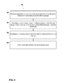
- a method 400 is provided for receiving an incoming signal with a set of antennas, calculating a detection channel, and returning an estimated unambiguous angle based on the detection channel.
- the method could be performed using any of the apparatus shown in FIGS. 1-3 and described above; however, other configurations could be used.
- FIG. 4 illustrates the steps in an example method, however, it is understood that in other embodiments, the steps may appear in different order and steps could be added, subtracted, or modified. Additionally, the steps may be performed in a linear manner (as shown) or may be performed in a parallel manner (not shown).
- Step 402 includes the vehicle receiving a radar signal at a radar unit with an array of antennas.
- the vehicle described in this method could be the vehicle 100 and/or vehicle 200 as illustrated and described in reference to FIGS. 1 and 2 , respectively.
- Receiving the radar signal could include receiving radio signals that are reflected from objects in the field of view of the radar system.
- a processor in the radar system may convert the received radar signals into data to relay for further processing. For example, the radar system may transmit a signal and receive a set of reflected signals back. The radar system may further identify distance and direction information to each object that causes reflections back to the vehicle.
- the reflected signals may be processed fully or in part by a server and communicated to the vehicle.
- Each antenna in the array has a respective phase associated with the antenna.
- Each pair of antennas in the antenna array has both a separation distance and a differential channel phase with each other respective antenna in the array.
- the array may be a non-linear array. Thus, for a non-linear array, the spacing between adjacent antenna elements is not constant.
- the system may alter which antennas in the set of antennas are turned on. Thus, the calculation of the unambiguous angle may be revised based on the set of antennas that are currently active. In further embodiments, the system may alter the frequency of operation. Upon the frequency of operation changing, the unambiguous angle may be revised.
- Step 404 includes calculating a detection channel.
- the detection channel is the difference between two different differential channel phases.
- the detection channel is the same as the detection channel described with respect to ⁇ above.
- For a single-wide detection channel one antenna element is in common in the each differential channel phase used to calculate the detection channel.
- For a double-wide detection channel no antenna elements are in common in the each differential channel phase used to calculate the detection channel.
- Step 406 includes calculating an estimated unambiguous angle based on the detection channel and the plurality of antenna spacings.
- the unambiguous angle is calculated based on setting the detection channel equal to 2 ⁇ , as discussed previously. Solving the expression, the unambiguous angle may be defined in terms of parameters of the radar system.
- the unambiguous angle is a function of the operation frequency of the radar and the antenna element spacing.
- the unambiguous angle is a function of the operation frequency of the radar and the difference between antenna element spacing between two different pairs of antennas.
- the spacing between antenna 1 and antenna 2 may be S and the spacing between antenna 2 and antenna 3 may be S+a.
- the unambiguous angle is a function of the operation frequency of the radar and the value a.
- Step 408 includes controlling the radar unit based on the unambiguous angle.
- the radar unit may include a DOA calculation.
- the DOA calculation may use the unambiguous angle to assist in the calculation of the DOA.
- the radar unit may calculate a confidence level associated with the DOA calculation based on the unambiguous angle.
- the radar unit may return the unambiguous angle to further processing systems of the vehicle. Further, the radar unit may have other calculations in which it may use the calculated unambiguous angle.
- the radar system may be designed based on set of design parameters.
- the disclosed methods can calculate the required antenna spacing.
- only the operation frequency is unknown.
- the antenna spacing and the desired unambiguous angle may define an appropriate operation frequency.
- the calculation of the unambiguous angle results in an equation with multiple variables. Depending on the specific design criteria, various different parameters of the system may be calculated.
- FIG. 5 is a schematic illustrating a conceptual partial view of an example computer program product that includes a computer program for executing a computer process on a computing device, arranged according to at least some embodiments presented herein.
- the example computer program product 500 is provided using a signal bearing medium 502 .
- the signal bearing medium 502 may include one or more programming instructions 504 that, when executed by one or more processors may provide functionality or portions of the functionality described above with respect to FIGS. 1-4 .
- the signal bearing medium 502 may encompass a computer-readable medium 506 , such as, but not limited to, a hard disk drive, a Compact Disc (CD), a Digital Video Disk (DVD), a digital tape, memory, etc.
- the signal bearing medium 502 may encompass a computer recordable medium 508 , such as, but not limited to, memory, read/write (R/W) CDs, R/W DVDs, etc.
- the signal bearing medium 502 may encompass a communications medium 510 , such as, but not limited to, a digital and/or an analog communication medium (e.g., a fiber optic cable, a waveguide, a wired communications link, a wireless communication link, etc.).
- a communications medium 510 such as, but not limited to, a digital and/or an analog communication medium (e.g., a fiber optic cable, a waveguide, a wired communications link, a wireless communication link, etc.).
- the signal bearing medium 502 may be conveyed by a wireless form of the communications medium 510 .
- the one or more programming instructions 504 may be, for example, computer executable and/or logic implemented instructions.
- a computing device such as the computer system 112 of FIG. 1 may be configured to provide various operations, functions, or actions in response to the programming instructions 504 conveyed to the computer system 112 by one or more of the computer readable medium 506 , the computer recordable medium 508 , and/or the communications medium 510 .
- the non-transitory computer readable medium could also be distributed among multiple data storage elements, which could be remotely located from each other.
- the computing device that executes some or all of the stored instructions could be a vehicle, such as the vehicle 200 illustrated in FIG. 2 .
- the computing device that executes some or all of the stored instructions could be another computing device, such as a server.
Landscapes
- Engineering & Computer Science (AREA)
- Radar, Positioning & Navigation (AREA)
- Remote Sensing (AREA)
- Physics & Mathematics (AREA)
- Computer Networks & Wireless Communication (AREA)
- General Physics & Mathematics (AREA)
- Electromagnetism (AREA)
- Traffic Control Systems (AREA)
- Radar Systems Or Details Thereof (AREA)
Abstract
Description
This substitution expression indicates that the ratio of the frequency of the radar signal (ω) divided by the speed of light (c) is equal to two pi (2π) divided by the wavelength (λ) of the radar signal.
In one example, the wavelength (λ) may be 4 millimeters (mm) and the spacing (S) may be 26 mm. Thus, when the values are used in the above equation, the unambiguous angle is 8.8 degrees. This may be too small for some practical applications.
Claims (20)
Priority Applications (1)
| Application Number | Priority Date | Filing Date | Title |
|---|---|---|---|
| US13/626,647 US8994581B1 (en) | 2012-09-25 | 2012-09-25 | Direction of arrival (DOA) estimation using multiple offset receive channels |
Applications Claiming Priority (1)
| Application Number | Priority Date | Filing Date | Title |
|---|---|---|---|
| US13/626,647 US8994581B1 (en) | 2012-09-25 | 2012-09-25 | Direction of arrival (DOA) estimation using multiple offset receive channels |
Publications (1)
| Publication Number | Publication Date |
|---|---|
| US8994581B1 true US8994581B1 (en) | 2015-03-31 |
Family
ID=52707851
Family Applications (1)
| Application Number | Title | Priority Date | Filing Date |
|---|---|---|---|
| US13/626,647 Active 2033-08-07 US8994581B1 (en) | 2012-09-25 | 2012-09-25 | Direction of arrival (DOA) estimation using multiple offset receive channels |
Country Status (1)
| Country | Link |
|---|---|
| US (1) | US8994581B1 (en) |
Cited By (43)
| Publication number | Priority date | Publication date | Assignee | Title |
|---|---|---|---|---|
| JP2014169922A (en) * | 2013-03-04 | 2014-09-18 | Denso Corp | Object recognition device |
| US20150217765A1 (en) * | 2014-02-05 | 2015-08-06 | Toyota Jidosha Kabushiki Kaisha | Collision prevention control apparatus |
| CN106249195A (en) * | 2015-06-12 | 2016-12-21 | 联想(北京)有限公司 | A kind of information processing method and electronic equipment |
| US20170102453A1 (en) * | 2015-10-07 | 2017-04-13 | Mando Corporation | Radar device for vehicle and method for estimating angle of target using same |
| US9746545B1 (en) * | 2014-12-16 | 2017-08-29 | L3 Technologies, Inc. | Monopulse arbitrary phase detection and removal |
| WO2017146824A1 (en) * | 2016-02-26 | 2017-08-31 | X Development Llc | Radar mounting estimation with unstructured data |
| US20170293024A1 (en) * | 2016-04-07 | 2017-10-12 | GM Global Technology Operations LLC | Cognitive transmission switching |
| CN108037481A (en) * | 2017-12-01 | 2018-05-15 | 天津大学 | The gradable thinned array frequency of robustness and DOA estimation method and device |
| WO2018104468A1 (en) | 2016-12-08 | 2018-06-14 | Iee International Electronics & Engineering S.A. | Direction of arrival estimation for automotive spread radar systems |
| WO2018115372A1 (en) | 2016-12-23 | 2018-06-28 | Iee International Electronics & Engineering S.A. | High-resolution 3d radar wave imaging device |
| WO2018140897A1 (en) * | 2017-01-27 | 2018-08-02 | Massachusetts Institute Of Technology | Extending footprint for localization using surface penetrating radar (spr) |
| CN108414967A (en) * | 2018-04-11 | 2018-08-17 | 华南理工大学 | Based on L gusts of underwater two-dimension Wave arrival direction estimating method and device of angle adjustable double |
| CN109188348A (en) * | 2018-10-11 | 2019-01-11 | 北京遥感设备研究所 | A kind of angle estimating method based on conformal array antenna and Bayesian network |
| US10215853B2 (en) | 2016-04-07 | 2019-02-26 | Uhnder, Inc. | Adaptive transmission and interference cancellation for MIMO radar |
| US10261179B2 (en) * | 2016-04-07 | 2019-04-16 | Uhnder, Inc. | Software defined automotive radar |
| US10281923B2 (en) | 2016-03-03 | 2019-05-07 | Uber Technologies, Inc. | Planar-beam, light detection and ranging system |
| US10324165B2 (en) | 2016-04-25 | 2019-06-18 | Uhnder, Inc. | PMCW—PMCW interference mitigation |
| US10338225B2 (en) * | 2015-12-15 | 2019-07-02 | Uber Technologies, Inc. | Dynamic LIDAR sensor controller |
| US10412368B2 (en) | 2013-03-15 | 2019-09-10 | Uber Technologies, Inc. | Methods, systems, and apparatus for multi-sensory stereo vision for robotics |
| US20190293798A1 (en) * | 2018-03-23 | 2019-09-26 | Veoneer Us Inc. | Localization by light sensors |
| US10479376B2 (en) | 2017-03-23 | 2019-11-19 | Uatc, Llc | Dynamic sensor selection for self-driving vehicles |
| US10536529B2 (en) | 2016-04-25 | 2020-01-14 | Uhnder Inc. | Vehicle radar system with a shared radar and communication system |
| US10620310B2 (en) * | 2016-11-29 | 2020-04-14 | Waymo Llc | Rotating radar platform |
| US10718856B2 (en) | 2016-05-27 | 2020-07-21 | Uatc, Llc | Vehicle sensor calibration system |
| US10746858B2 (en) | 2017-08-17 | 2020-08-18 | Uatc, Llc | Calibration for an autonomous vehicle LIDAR module |
| US10775488B2 (en) | 2017-08-17 | 2020-09-15 | Uatc, Llc | Calibration for an autonomous vehicle LIDAR module |
| CN111856414A (en) * | 2019-04-08 | 2020-10-30 | 是德科技股份有限公司 | Dynamic echo signal simulation for automotive radar sensor configuration |
| US10877149B2 (en) * | 2014-09-25 | 2020-12-29 | Audi Ag | Method for operating a multiplicity of radar sensors in a motor vehicle and motor vehicle |
| US10914820B2 (en) | 2018-01-31 | 2021-02-09 | Uatc, Llc | Sensor assembly for vehicles |
| CN112385154A (en) * | 2018-06-20 | 2021-02-19 | 电装国际美国公司 | Circularly polarized arrival angle measuring system |
| US10935633B2 (en) | 2017-02-10 | 2021-03-02 | Uhnder, Inc. | Programmable code generation for radar sensing systems |
| US11086010B2 (en) | 2016-04-07 | 2021-08-10 | Uhnder, Inc. | Software defined automotive radar systems |
| US11105890B2 (en) | 2017-12-14 | 2021-08-31 | Uhnder, Inc. | Frequency modulated signal cancellation in variable power mode for radar applications |
| US20210293949A1 (en) * | 2020-03-17 | 2021-09-23 | HELLA GmbH & Co. KGaA | Method for determining direction information |
| US11194016B2 (en) | 2016-04-25 | 2021-12-07 | Uhnder, Inc. | Digital frequency modulated continuous wave radar using handcrafted constant envelope modulation |
| EP4053592A1 (en) * | 2021-03-02 | 2022-09-07 | Nxp B.V. | Method and system for single target direction of arrival estimation for sparse array radar systems |
| US11454697B2 (en) | 2017-02-10 | 2022-09-27 | Uhnder, Inc. | Increasing performance of a receive pipeline of a radar with memory optimization |
| US11474225B2 (en) | 2018-11-09 | 2022-10-18 | Uhnder, Inc. | Pulse digital mimo radar system |
| US11681017B2 (en) | 2019-03-12 | 2023-06-20 | Uhnder, Inc. | Method and apparatus for mitigation of low frequency noise in radar systems |
| EP4220223A1 (en) * | 2022-01-26 | 2023-08-02 | Aptiv Technologies Limited | Radar device |
| US11740323B2 (en) | 2016-06-20 | 2023-08-29 | Uhnder, Inc. | Power control for improved near-far performance of radar systems |
| US11846696B2 (en) | 2017-02-10 | 2023-12-19 | Uhnder, Inc. | Reduced complexity FFT-based correlation for automotive radar |
| US11899126B2 (en) | 2020-01-13 | 2024-02-13 | Uhnder, Inc. | Method and system for multi-chip operation of radar systems |
Citations (13)
| Publication number | Priority date | Publication date | Assignee | Title |
|---|---|---|---|---|
| US4467328A (en) * | 1981-10-26 | 1984-08-21 | Westinghouse Electric Corp. | Radar jammer with an antenna array of pseudo-randomly spaced radiating elements |
| US4780722A (en) * | 1986-04-18 | 1988-10-25 | U.S. Philips Corporation | Radio direction-finding |
| US5812091A (en) * | 1996-02-01 | 1998-09-22 | Robinson; Stephen J. | Radio interferometric antenna for angle coding |
| US6313794B1 (en) * | 2000-01-19 | 2001-11-06 | Litton Systems, Inc. | Method of detection and determining an angular location of frequency agile emitters |
| US20070285315A1 (en) * | 2004-01-13 | 2007-12-13 | Davis Dennis W | Phase arrays exploiting geometry phase and methods of creating such arrays |
| US20080291088A1 (en) * | 2006-01-23 | 2008-11-27 | Murata Manufacturing, Co., Ltd. | Radar Apparatus |
| US7477192B1 (en) | 2007-02-22 | 2009-01-13 | L-3 Communications Titan Corporation | Direction finding system and method |
| US7613482B2 (en) | 2005-12-08 | 2009-11-03 | Accton Technology Corporation | Method and system for steering antenna beam |
| US20100225523A1 (en) * | 2009-03-04 | 2010-09-09 | Denso Corporation | Radar apparatus configured to suppress effectes of grating lobes upon detection of direction of target based on phase difference between received reflected waves |
| US8019285B2 (en) | 2006-09-29 | 2011-09-13 | Fujitsu Limited | Wireless communication device |
| US20110298676A1 (en) * | 2009-10-22 | 2011-12-08 | Toyota Motor Europe Nv/Sa | Antenna having sparsely populated array of elements |
| US20110304508A1 (en) | 2010-06-10 | 2011-12-15 | Jacob Remez | Direction finding antenna system and method |
| WO2011158056A1 (en) | 2010-06-19 | 2011-12-22 | Nokia Corporation | Method and apparatus for estimating direction of arrival |
-
2012
- 2012-09-25 US US13/626,647 patent/US8994581B1/en active Active
Patent Citations (13)
| Publication number | Priority date | Publication date | Assignee | Title |
|---|---|---|---|---|
| US4467328A (en) * | 1981-10-26 | 1984-08-21 | Westinghouse Electric Corp. | Radar jammer with an antenna array of pseudo-randomly spaced radiating elements |
| US4780722A (en) * | 1986-04-18 | 1988-10-25 | U.S. Philips Corporation | Radio direction-finding |
| US5812091A (en) * | 1996-02-01 | 1998-09-22 | Robinson; Stephen J. | Radio interferometric antenna for angle coding |
| US6313794B1 (en) * | 2000-01-19 | 2001-11-06 | Litton Systems, Inc. | Method of detection and determining an angular location of frequency agile emitters |
| US20070285315A1 (en) * | 2004-01-13 | 2007-12-13 | Davis Dennis W | Phase arrays exploiting geometry phase and methods of creating such arrays |
| US7613482B2 (en) | 2005-12-08 | 2009-11-03 | Accton Technology Corporation | Method and system for steering antenna beam |
| US20080291088A1 (en) * | 2006-01-23 | 2008-11-27 | Murata Manufacturing, Co., Ltd. | Radar Apparatus |
| US8019285B2 (en) | 2006-09-29 | 2011-09-13 | Fujitsu Limited | Wireless communication device |
| US7477192B1 (en) | 2007-02-22 | 2009-01-13 | L-3 Communications Titan Corporation | Direction finding system and method |
| US20100225523A1 (en) * | 2009-03-04 | 2010-09-09 | Denso Corporation | Radar apparatus configured to suppress effectes of grating lobes upon detection of direction of target based on phase difference between received reflected waves |
| US20110298676A1 (en) * | 2009-10-22 | 2011-12-08 | Toyota Motor Europe Nv/Sa | Antenna having sparsely populated array of elements |
| US20110304508A1 (en) | 2010-06-10 | 2011-12-15 | Jacob Remez | Direction finding antenna system and method |
| WO2011158056A1 (en) | 2010-06-19 | 2011-12-22 | Nokia Corporation | Method and apparatus for estimating direction of arrival |
Non-Patent Citations (2)
| Title |
|---|
| Buckley, E., "Ambiguity suppression in a multiple beam radar," RADAR 2002 , vol., no., pp. 492,496, Oct. 15-17, 2002. * |
| Haowen Chen; Xiang Li; Weidong Jiang; Zhaowen Zhuang, "MIMO Radar Sensitivity Analysis of Antenna Position for Direction Finding," Signal Processing, IEEE Transactions on , vol. 60, No. 10, pp. 5201,5216, Oct. 2012. * |
Cited By (75)
| Publication number | Priority date | Publication date | Assignee | Title |
|---|---|---|---|---|
| JP2014169922A (en) * | 2013-03-04 | 2014-09-18 | Denso Corp | Object recognition device |
| US10412368B2 (en) | 2013-03-15 | 2019-09-10 | Uber Technologies, Inc. | Methods, systems, and apparatus for multi-sensory stereo vision for robotics |
| US20150217765A1 (en) * | 2014-02-05 | 2015-08-06 | Toyota Jidosha Kabushiki Kaisha | Collision prevention control apparatus |
| US9481365B2 (en) * | 2014-02-05 | 2016-11-01 | Toyota Jidosha Kabushiki Kaisha | Collision prevention control apparatus |
| US10877149B2 (en) * | 2014-09-25 | 2020-12-29 | Audi Ag | Method for operating a multiplicity of radar sensors in a motor vehicle and motor vehicle |
| US9746545B1 (en) * | 2014-12-16 | 2017-08-29 | L3 Technologies, Inc. | Monopulse arbitrary phase detection and removal |
| CN106249195A (en) * | 2015-06-12 | 2016-12-21 | 联想(北京)有限公司 | A kind of information processing method and electronic equipment |
| US20170102453A1 (en) * | 2015-10-07 | 2017-04-13 | Mando Corporation | Radar device for vehicle and method for estimating angle of target using same |
| US10732273B2 (en) * | 2015-10-07 | 2020-08-04 | Mando Corporation | Radar device for vehicle and method for estimating angle of target using same |
| US10677925B2 (en) * | 2015-12-15 | 2020-06-09 | Uatc, Llc | Adjustable beam pattern for lidar sensor |
| US11740355B2 (en) | 2015-12-15 | 2023-08-29 | Uatc, Llc | Adjustable beam pattern for LIDAR sensor |
| US10338225B2 (en) * | 2015-12-15 | 2019-07-02 | Uber Technologies, Inc. | Dynamic LIDAR sensor controller |
| US11016174B2 (en) | 2016-02-26 | 2021-05-25 | Waymo Llc | Radar mounting estimation with unstructured data |
| WO2017146824A1 (en) * | 2016-02-26 | 2017-08-31 | X Development Llc | Radar mounting estimation with unstructured data |
| US10191144B2 (en) | 2016-02-26 | 2019-01-29 | Waymo Llc | Radar mounting estimation with unstructured data |
| CN109313262A (en) * | 2016-02-26 | 2019-02-05 | 伟摩有限责任公司 | Radar installation estimation is carried out using unstructured data |
| US10281923B2 (en) | 2016-03-03 | 2019-05-07 | Uber Technologies, Inc. | Planar-beam, light detection and ranging system |
| US11604475B2 (en) | 2016-03-03 | 2023-03-14 | Uatc, Llc | Planar-beam, light detection and ranging system |
| US10942524B2 (en) | 2016-03-03 | 2021-03-09 | Uatc, Llc | Planar-beam, light detection and ranging system |
| US10261179B2 (en) * | 2016-04-07 | 2019-04-16 | Uhnder, Inc. | Software defined automotive radar |
| US10215853B2 (en) | 2016-04-07 | 2019-02-26 | Uhnder, Inc. | Adaptive transmission and interference cancellation for MIMO radar |
| US20170293024A1 (en) * | 2016-04-07 | 2017-10-12 | GM Global Technology Operations LLC | Cognitive transmission switching |
| US11614538B2 (en) | 2016-04-07 | 2023-03-28 | Uhnder, Inc. | Software defined automotive radar |
| US11262448B2 (en) * | 2016-04-07 | 2022-03-01 | Uhnder, Inc. | Software defined automotive radar |
| US11906620B2 (en) | 2016-04-07 | 2024-02-20 | Uhnder, Inc. | Software defined automotive radar systems |
| US11086010B2 (en) | 2016-04-07 | 2021-08-10 | Uhnder, Inc. | Software defined automotive radar systems |
| US11821981B2 (en) * | 2016-04-07 | 2023-11-21 | Uhnder, Inc. | Software defined automotive radar |
| US11175377B2 (en) | 2016-04-25 | 2021-11-16 | Uhnder, Inc. | PMCW-PMCW interference mitigation |
| US11194016B2 (en) | 2016-04-25 | 2021-12-07 | Uhnder, Inc. | Digital frequency modulated continuous wave radar using handcrafted constant envelope modulation |
| US10536529B2 (en) | 2016-04-25 | 2020-01-14 | Uhnder Inc. | Vehicle radar system with a shared radar and communication system |
| US11582305B2 (en) | 2016-04-25 | 2023-02-14 | Uhnder, Inc. | Vehicle radar system with a shared radar and communication system |
| US10324165B2 (en) | 2016-04-25 | 2019-06-18 | Uhnder, Inc. | PMCW—PMCW interference mitigation |
| US10718856B2 (en) | 2016-05-27 | 2020-07-21 | Uatc, Llc | Vehicle sensor calibration system |
| US11009594B2 (en) | 2016-05-27 | 2021-05-18 | Uatc, Llc | Vehicle sensor calibration system |
| US11740323B2 (en) | 2016-06-20 | 2023-08-29 | Uhnder, Inc. | Power control for improved near-far performance of radar systems |
| US10620310B2 (en) * | 2016-11-29 | 2020-04-14 | Waymo Llc | Rotating radar platform |
| US10884113B2 (en) | 2016-12-08 | 2021-01-05 | Iee International Electronics & Engineering S.A. | Direction of arrival estimation for automotive spread radar systems |
| WO2018104468A1 (en) | 2016-12-08 | 2018-06-14 | Iee International Electronics & Engineering S.A. | Direction of arrival estimation for automotive spread radar systems |
| US11675070B2 (en) | 2016-12-23 | 2023-06-13 | Iee International Electronics & Engineering S.A. | High-resolution 3D radar wave imaging device |
| WO2018115372A1 (en) | 2016-12-23 | 2018-06-28 | Iee International Electronics & Engineering S.A. | High-resolution 3d radar wave imaging device |
| WO2018140897A1 (en) * | 2017-01-27 | 2018-08-02 | Massachusetts Institute Of Technology | Extending footprint for localization using surface penetrating radar (spr) |
| US11402493B2 (en) | 2017-01-27 | 2022-08-02 | Massachusetts Institute Of Technology | Determining surface characteristics |
| US10663579B2 (en) | 2017-01-27 | 2020-05-26 | Massachusetts Institute Of Technology | Extending footprint for localization using surface penetrating radar (SPR) |
| US10746867B2 (en) | 2017-01-27 | 2020-08-18 | Massachusetts Institute Of Technology | Determining surface characteristics |
| US10725171B2 (en) | 2017-01-27 | 2020-07-28 | Massachusetts Institute Of Technology | Method and system for localization of a vehicle using surface penetrating radar |
| US10935633B2 (en) | 2017-02-10 | 2021-03-02 | Uhnder, Inc. | Programmable code generation for radar sensing systems |
| US11726172B2 (en) | 2017-02-10 | 2023-08-15 | Uhnder, Inc | Programmable code generation for radar sensing systems |
| US11454697B2 (en) | 2017-02-10 | 2022-09-27 | Uhnder, Inc. | Increasing performance of a receive pipeline of a radar with memory optimization |
| US11846696B2 (en) | 2017-02-10 | 2023-12-19 | Uhnder, Inc. | Reduced complexity FFT-based correlation for automotive radar |
| US10479376B2 (en) | 2017-03-23 | 2019-11-19 | Uatc, Llc | Dynamic sensor selection for self-driving vehicles |
| US10746858B2 (en) | 2017-08-17 | 2020-08-18 | Uatc, Llc | Calibration for an autonomous vehicle LIDAR module |
| US10775488B2 (en) | 2017-08-17 | 2020-09-15 | Uatc, Llc | Calibration for an autonomous vehicle LIDAR module |
| CN108037481A (en) * | 2017-12-01 | 2018-05-15 | 天津大学 | The gradable thinned array frequency of robustness and DOA estimation method and device |
| US11867828B2 (en) | 2017-12-14 | 2024-01-09 | Uhnder, Inc. | Frequency modulated signal cancellation in variable power mode for radar applications |
| US11105890B2 (en) | 2017-12-14 | 2021-08-31 | Uhnder, Inc. | Frequency modulated signal cancellation in variable power mode for radar applications |
| US10914820B2 (en) | 2018-01-31 | 2021-02-09 | Uatc, Llc | Sensor assembly for vehicles |
| US11747448B2 (en) | 2018-01-31 | 2023-09-05 | Uatc, Llc | Sensor assembly for vehicles |
| US10877156B2 (en) * | 2018-03-23 | 2020-12-29 | Veoneer Us Inc. | Localization by light sensors |
| US20190293798A1 (en) * | 2018-03-23 | 2019-09-26 | Veoneer Us Inc. | Localization by light sensors |
| CN108414967A (en) * | 2018-04-11 | 2018-08-17 | 华南理工大学 | Based on L gusts of underwater two-dimension Wave arrival direction estimating method and device of angle adjustable double |
| CN112385154A (en) * | 2018-06-20 | 2021-02-19 | 电装国际美国公司 | Circularly polarized arrival angle measuring system |
| CN109188348A (en) * | 2018-10-11 | 2019-01-11 | 北京遥感设备研究所 | A kind of angle estimating method based on conformal array antenna and Bayesian network |
| US11474225B2 (en) | 2018-11-09 | 2022-10-18 | Uhnder, Inc. | Pulse digital mimo radar system |
| US11681017B2 (en) | 2019-03-12 | 2023-06-20 | Uhnder, Inc. | Method and apparatus for mitigation of low frequency noise in radar systems |
| US11977178B2 (en) | 2019-03-12 | 2024-05-07 | Uhnder, Inc. | Multi-chip synchronization for digital radars |
| CN111856414A (en) * | 2019-04-08 | 2020-10-30 | 是德科技股份有限公司 | Dynamic echo signal simulation for automotive radar sensor configuration |
| US11899126B2 (en) | 2020-01-13 | 2024-02-13 | Uhnder, Inc. | Method and system for multi-chip operation of radar systems |
| US12078748B2 (en) | 2020-01-13 | 2024-09-03 | Uhnder, Inc. | Method and system for intefrence management for digital radars |
| US11953615B2 (en) | 2020-01-13 | 2024-04-09 | Uhnder Inc. | Method and system for antenna array calibration for cross-coupling and gain/phase variations in radar systems |
| US20210293949A1 (en) * | 2020-03-17 | 2021-09-23 | HELLA GmbH & Co. KGaA | Method for determining direction information |
| US11921188B2 (en) * | 2020-03-17 | 2024-03-05 | HELLA GmbH & Co. KGaA | Method for determining direction information |
| US11573312B2 (en) * | 2021-03-02 | 2023-02-07 | Nxp B.V. | Method and system for single target direction of arrival estimation for sparse array radar systems |
| US20220283283A1 (en) * | 2021-03-02 | 2022-09-08 | Nxp B.V. | Method and System for Single Target Direction of Arrival Estimation for Sparse Array Radar Systems |
| EP4053592A1 (en) * | 2021-03-02 | 2022-09-07 | Nxp B.V. | Method and system for single target direction of arrival estimation for sparse array radar systems |
| EP4220223A1 (en) * | 2022-01-26 | 2023-08-02 | Aptiv Technologies Limited | Radar device |
Similar Documents
| Publication | Publication Date | Title |
|---|---|---|
| US8994581B1 (en) | Direction of arrival (DOA) estimation using multiple offset receive channels | |
| US11531353B2 (en) | Calculating velocity of an autonomous vehicle using radar technology | |
| US10473780B1 (en) | Use of motion data in the processing of automotive radar image processing | |
| US11802953B2 (en) | Adaptive algorithms for interrogating the viewable scene of an automotive radar | |
| US11835624B2 (en) | Radar based mapping and localization for autonomous vehicles | |
| CN109844562B (en) | Radar generated occupancy grid for autonomous vehicle awareness and planning | |
| US9261590B1 (en) | Adaptive algorithms for interrogating the viewable scene of an automotive radar | |
| KR102307220B1 (en) | Motion detection of autonomous vehicles using radar technology | |
| EP3186659B1 (en) | Methods and systems for vehicle radar coordinaton and interference reduction | |
| US8676427B1 (en) | Controlling autonomous vehicle using audio data | |
| US10923829B2 (en) | Vehicle-mounted radar deflectors | |
| US10691135B2 (en) | Detecting motion of an autonomous vehicle using radar technology | |
| US10967856B2 (en) | Detection of pedestrian using radio devices | |
| US9178258B1 (en) | Split-block construction of waveguide channels for radar frontend | |
| US10490900B1 (en) | Free-space matched waveguide flange | |
| CN113049846A (en) | System and method for measuring trailer wheel speed |
Legal Events
| Date | Code | Title | Description |
|---|---|---|---|
| AS | Assignment |
Owner name: GOOGLE INC., CALIFORNIA Free format text: ASSIGNMENT OF ASSIGNORS INTEREST;ASSIGNOR:BROWN, ADAM;REEL/FRAME:029023/0108 Effective date: 20120925 |
|
| STCF | Information on status: patent grant |
Free format text: PATENTED CASE |
|
| AS | Assignment |
Owner name: WAYMO HOLDING INC., CALIFORNIA Free format text: ASSIGNMENT OF ASSIGNORS INTEREST;ASSIGNOR:GOOGLE INC.;REEL/FRAME:042084/0741 Effective date: 20170321 Owner name: WAYMO LLC, CALIFORNIA Free format text: ASSIGNMENT OF ASSIGNORS INTEREST;ASSIGNOR:WAYMO HOLDING INC.;REEL/FRAME:042085/0001 Effective date: 20170322 |
|
| MAFP | Maintenance fee payment |
Free format text: PAYMENT OF MAINTENANCE FEE, 4TH YEAR, LARGE ENTITY (ORIGINAL EVENT CODE: M1551); ENTITY STATUS OF PATENT OWNER: LARGE ENTITY Year of fee payment: 4 |
|
| MAFP | Maintenance fee payment |
Free format text: PAYMENT OF MAINTENANCE FEE, 8TH YEAR, LARGE ENTITY (ORIGINAL EVENT CODE: M1552); ENTITY STATUS OF PATENT OWNER: LARGE ENTITY Year of fee payment: 8 |