EP1903314B1 - Procédé de détection d'origine pour codeur optique - Google Patents
Procédé de détection d'origine pour codeur optique Download PDFInfo
- Publication number
- EP1903314B1 EP1903314B1 EP07018090.6A EP07018090A EP1903314B1 EP 1903314 B1 EP1903314 B1 EP 1903314B1 EP 07018090 A EP07018090 A EP 07018090A EP 1903314 B1 EP1903314 B1 EP 1903314B1
- Authority
- EP
- European Patent Office
- Prior art keywords
- scale
- light receiving
- receiving means
- output signal
- signal
- Prior art date
- Legal status (The legal status is an assumption and is not a legal conclusion. Google has not performed a legal analysis and makes no representation as to the accuracy of the status listed.)
- Not-in-force
Links
- 230000003287 optical effect Effects 0.000 title claims description 19
- 238000001514 detection method Methods 0.000 title description 13
- 238000004364 calculation method Methods 0.000 claims description 16
- 239000011295 pitch Substances 0.000 claims description 11
- 238000012545 processing Methods 0.000 description 10
- 230000007423 decrease Effects 0.000 description 8
- 238000002834 transmittance Methods 0.000 description 7
- 230000003247 decreasing effect Effects 0.000 description 5
- 230000000630 rising effect Effects 0.000 description 5
- 230000002950 deficient Effects 0.000 description 2
- 238000010586 diagram Methods 0.000 description 2
- 238000005259 measurement Methods 0.000 description 2
- 230000002441 reversible effect Effects 0.000 description 2
- 238000005070 sampling Methods 0.000 description 2
- 238000007796 conventional method Methods 0.000 description 1
- 238000011161 development Methods 0.000 description 1
- 230000018109 developmental process Effects 0.000 description 1
- 230000004069 differentiation Effects 0.000 description 1
- 230000005693 optoelectronics Effects 0.000 description 1
- 230000001360 synchronised effect Effects 0.000 description 1
Images


Classifications
-
- G—PHYSICS
- G01—MEASURING; TESTING
- G01D—MEASURING NOT SPECIALLY ADAPTED FOR A SPECIFIC VARIABLE; ARRANGEMENTS FOR MEASURING TWO OR MORE VARIABLES NOT COVERED IN A SINGLE OTHER SUBCLASS; TARIFF METERING APPARATUS; MEASURING OR TESTING NOT OTHERWISE PROVIDED FOR
- G01D5/00—Mechanical means for transferring the output of a sensing member; Means for converting the output of a sensing member to another variable where the form or nature of the sensing member does not constrain the means for converting; Transducers not specially adapted for a specific variable
- G01D5/26—Mechanical means for transferring the output of a sensing member; Means for converting the output of a sensing member to another variable where the form or nature of the sensing member does not constrain the means for converting; Transducers not specially adapted for a specific variable characterised by optical transfer means, i.e. using infrared, visible, or ultraviolet light
- G01D5/32—Mechanical means for transferring the output of a sensing member; Means for converting the output of a sensing member to another variable where the form or nature of the sensing member does not constrain the means for converting; Transducers not specially adapted for a specific variable characterised by optical transfer means, i.e. using infrared, visible, or ultraviolet light with attenuation or whole or partial obturation of beams of light
- G01D5/34—Mechanical means for transferring the output of a sensing member; Means for converting the output of a sensing member to another variable where the form or nature of the sensing member does not constrain the means for converting; Transducers not specially adapted for a specific variable characterised by optical transfer means, i.e. using infrared, visible, or ultraviolet light with attenuation or whole or partial obturation of beams of light the beams of light being detected by photocells
- G01D5/347—Mechanical means for transferring the output of a sensing member; Means for converting the output of a sensing member to another variable where the form or nature of the sensing member does not constrain the means for converting; Transducers not specially adapted for a specific variable characterised by optical transfer means, i.e. using infrared, visible, or ultraviolet light with attenuation or whole or partial obturation of beams of light the beams of light being detected by photocells using displacement encoding scales
- G01D5/34707—Scales; Discs, e.g. fixation, fabrication, compensation
-
- G—PHYSICS
- G01—MEASURING; TESTING
- G01D—MEASURING NOT SPECIALLY ADAPTED FOR A SPECIFIC VARIABLE; ARRANGEMENTS FOR MEASURING TWO OR MORE VARIABLES NOT COVERED IN A SINGLE OTHER SUBCLASS; TARIFF METERING APPARATUS; MEASURING OR TESTING NOT OTHERWISE PROVIDED FOR
- G01D5/00—Mechanical means for transferring the output of a sensing member; Means for converting the output of a sensing member to another variable where the form or nature of the sensing member does not constrain the means for converting; Transducers not specially adapted for a specific variable
- G01D5/12—Mechanical means for transferring the output of a sensing member; Means for converting the output of a sensing member to another variable where the form or nature of the sensing member does not constrain the means for converting; Transducers not specially adapted for a specific variable using electric or magnetic means
- G01D5/244—Mechanical means for transferring the output of a sensing member; Means for converting the output of a sensing member to another variable where the form or nature of the sensing member does not constrain the means for converting; Transducers not specially adapted for a specific variable using electric or magnetic means influencing characteristics of pulses or pulse trains; generating pulses or pulse trains
- G01D5/245—Mechanical means for transferring the output of a sensing member; Means for converting the output of a sensing member to another variable where the form or nature of the sensing member does not constrain the means for converting; Transducers not specially adapted for a specific variable using electric or magnetic means influencing characteristics of pulses or pulse trains; generating pulses or pulse trains using a variable number of pulses in a train
- G01D5/2454—Encoders incorporating incremental and absolute signals
- G01D5/2455—Encoders incorporating incremental and absolute signals with incremental and absolute tracks on the same encoder
- G01D5/2457—Incremental encoders having reference marks
Definitions
- the present invention relates to an origin detection method for an optical encoder that is used in displace measurement or angle measurement.
- a photoelectric encoder has a main scale on which a first optical grating is provided and an index scale opposed thereto on which a second optical grating is provided.
- the photoelectric encoder further has a light source that illuminates the main scale with light and a light receiving element that receives light having been transmitted through or reflected by the optical grating of the main scale and transmitted through the optical grating of the index scale.
- Japanese Patent Publication No. H06-056304 teaches use of a light receiving element array that also functions as an index scale in a photoelectric encoder of the above described type.
- the inventors of the present invention have also filed patent applications, e.g. Japanese Patent Application Laid-Open No. 2003-161645 , on inventions concerning encoders of the above described type, see also US 2005/0274880 .
- EP 1 691 172 discloses an optical position measuring system with an optoelectronic detector arrangement suitable for detecting a reference pulse signal from a reference marking integrated in an incremental gradation track of a scale.
- the encoder having the above described structure is called an incremental type encoder.
- This type of encoder detects the movement amount of a scale by counting the number of output pulses generated by movement of the scale.
- a problem encountered with the incremental type encoder is that the absolute position in the rotational angle cannot be determined, and it is required, in some cases, to provide an additional separate sensor to detect the absolute position.
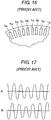
- FIG. 16 shows a scale disclosed in Japanese Patent Application Laid-Open No. H10-318790 , in which the transmittance of the pattern on the scale 1 is varied to enable to detect the absolute position in an incremental type encoder.
- mark la has a transmittance of 1, and transmittances of marks 1b, 1c, 1d ... gradually decrease.
- FIG. 17 shows changes in signals that occur when a portion of the scale 1 in which the transmittance varies passes by a sensor in an encoder having this scale 1.
- Signals A and B are analogue two phase signals obtained from the sensor.
- the amplitude of the signals decreases with a gradual decrease in the transmittance of the mark of the scale 1, and the absolute position can be detected by detecting this change in the signal amplitude.
- an absolute position detection unit used in the above described conventional encoder, in order to detect the signal amplitude, it is required to sample signals at intervals significantly shorter than a cycle of the encoder signals obtained.
- An object of the present invention is to provide an origin detection method for an optical encoder that enables origin detection with a simple structure by performing computation according to changes in the sensor signal with movement of a scale.
- an optical encoder as defined in claim 1.
- the other claims relate to further developments.
- the origin position in detecting the absolute position, can be determined by detecting a point of change in an analogue middle voltage based on a relationship between the number of units of the light receiving portion and the discontinuous portion of the scale.
- an encoder signal and an origin signal are synchronous signals obtained from the same scale, a highly accurate origin signal can be produced. Furthermore, no additional parts are needed to detect the origin, and accordingly, encoders having an origin position detection function can be manufactured at low cost.
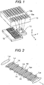
- FIG. 1 schematically shows the structure of an encoder that uses a micro roof mirror array as a reflective scale.
- the encoder has a light emitting portion 11, a light receiving portion 12 and a scale 13 as a moving member. Light emitted from the light emitting portion 11 is reflected by the scale 13 that has a reflexive portion 13a and an irreflexive portion 13b, so that a light-and-shade distribution pattern is formed on an array of photodiodes 14 serving as light receiving elements in the light receiving portion 12 shown in FIG. 2 .
- FIG. 1 shows only a part of the scale 13.
- the scale 13 is long in its moving direction and has a region 13a in which reflexive portions and irreflexive portions are arranged at a certain cycle and a partial region 13b in which a reflexive portion is absent.
- the scale 13 is not necessarily required to have micro roof mirror array, but it may be a simple structure having reflexive portions and irreflexive portions.
- the light receiving portion 12 shown in FIG. 2 has a plurality of units, each of which includes four photodiodes 14.
- the length of the unit including four photodiodes 14 corresponds to the length of one light-and-shade cycle of the scale 13.
- the light receiving portion 12 shown in FIG. 2 has six units. By performing computation based on signals obtained from the four photodiodes 14, two phase sinusoidal signals having a phase difference of 90 degrees can be obtained.
- High intensity portions La of the light incident on the light receiving portion 12 from the scale 13 are distributed in a specific relation with respect to the scale pitch. Thus, there is a high light intensity portion La in one unit in the light receiving portion 12. In this embodiment, since the irreflexive portion 13b is provided on the scale 13, a low light intensity portion Lb is generated among the high light intensity portions La.
- the light receiving portion 12 is adapted to receive six high light intensity portions La, and one of the six high light intensity portions is absent. Therefore, a light quantity equal to five sixths of the normal light quantity is obtained.
- Corresponding photodiodes in the respective units may be interconnected so that an added-up signal is output, or a circuit that adds up the signals output from those photodiodes may be provided.
- FIG. 3 is a circuit diagram of a processing circuit in this embodiment.
- the processing circuit has current-to-voltage converters provided downstream of the four photodiodes 14a to 14d in one unit respectively.
- the photodiodes 14a to 14d output signals having phase differences of 90 degrees from one another.
- Signals from photodiodes 14a and 14c and signals from photodiodes 14b and 14d have phase differences of 180 degrees respectively. These signals are input to analogue amplifiers 21a to 21d. The outputs of the analogue amplifiers 21a to 21d are input to the plus and minus terminals of comparators 22a and 22b so as to be binarized. Thus, an A-phase digital signal DA and a B-phase digital signal DB are output.
- the outputs of the analogue amplifiers 21a to 21d are connected to differential amplifiers 23a and 23b, and a voltage Vref2 is applied to the differential amplifiers 23a and 23b. Therefore, an A-phase analogue signal A and a B-phase analogue signal B in which the voltage Vref2 is the central voltage in the analogue signals A and B are output.
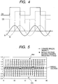
- FIG. 4 shows waveforms of signals obtained from this circuit. Since the digital signals DA, DB are generated at zero crossing points of the analogue signals A, B, and the phases of the analogue signals A and B are different from each other by 90 degrees, rising edges and trailing edges of the B-phase digital signal DB coincide with times at which the A-phase analogue signal A becomes maximum and minimum.
- the maximum value and the minimum value of the A-phase analogue signal A in one cycle thereof can be obtained.
- FIG. 5 shows a detection signal of the value of the A-phase analogue signal A obtained by using the light receiving portion 12 in FIG. 2 at timings of rising and trailing edges of the digital signals DA, DB in a case where the width of the irreflexive portion 13b on the scale 13 is equal to the width of one slit.
- the amplitude (Amax - Amin) is relatively small over 6 cycles.
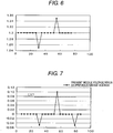
- FIG. 6 shows the middle voltage in an enlarged manner.
- the middle voltage increases or decreases at a moment when the irreflexive portion 13b of the scale 13 passes by the light receiving portion 12.
- the irreflexive portion 13b passes from analogue-signal-A side (passes from the photodiode 14a toward the photodiode 14d in FIG. 3 )
- a decrease in the middle voltage occurs.
- an increase in the middle voltage occurs.
- such signal characteristics can change depending on the wiring of the photodiodes 14, and the above described signal characteristics are not always the case.
- FIG. 7 is a graph showing the difference between the middle voltage data shown in FIG. 6 and the sixth-previous middle voltage data.
- the increased portion and the decreased portion in the middle voltage appear at an interval of six (that is, the number of units), and accordingly, the aforementioned difference can show the position at which the signal changes in an exaggerated manner.
- the origin position can be determined by specifying a point as the origin through a signal processing when the difference between the middle voltage data obtained and the sixth-previous middle voltage data exceeds a certain threshold level (LV1).
- LV1 threshold level
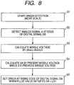
- FIG. 8 is a flow chart of the algorithm according to this detection method.
- Step S1 Origin detection is started. The scale 13 is moved, and signals are generated.
- Step S2 The maximum values Amax and the minimum values Amin of the A-phase analogue signal A are detected by detecting the value of the A-phase analogue signal A at timings of rising edges and trailing edges of the B-phase digital signal DB.
- Step S3 The middle voltage of the A-phase analogue signal A is calculated as (Amax + Amin)/2.
- Step S4 Value SA is calculated as the current middle voltage data minus the sixth-previous middle voltage data.
- Step S5 The origin is set at the rising edge of the A-phase digital signal DA at the time when the pulse value satisfies the condition "SA > threshold level LV1".
- the origin position can be determined with high accuracy.
- the origin position can be determined in a simple manner with reliability.
- FIG. 9 schematically shows the structure of an encoder according to a second embodiment of the present invention.
- the scale 13 in the first embodiment shown in FIG. 1 is provided with one irreflexive portion or slit 13b, the scale 13 of the second embodiment is provided with two irreflexive portions 13b, 13b' arranged continuously.
- FIG. 10 shows a signal waveform of the A-phase analogue signal A retrieved at pulse edges of the digital signals DA, DB and the middle voltage between the minimum value Amin and the maximum value Amax when the analogue signal A changes from the minimum value Amin to the maximum value Amax in the case where the scale is provided with two irreflexive portions 13b, 13b'.
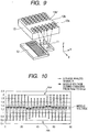
- FIG. 11 shows the middle voltage of the A-phase analogue signal in an enlarged manner. What is different in this graph from the corresponding graph in the first embodiment is that two successive decreased portions and two successive increased portions occur in the middle voltage. As will be seen from FIG. 11 , the increased portion and the decreased portion in the middle voltage level appear at an interval of six (that is, the number of units), and the portion in which the reflexive portion is absent includes two sections. Therefore, the difference between the current data and the sixth-previous data shows a peak portion that includes two detection points.
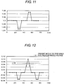
- FIG. 12 is a graph showing the difference between the current data and the fifth-previous data.
- the difference between the current data and the fifth-previous data is calculated.
- the peak portion of the resultant detection signal includes one detection point, and the origin position can be determined.
- the origin position can be determined by signal processing as a point at which the difference between the middle voltage data obtained and the fifth-previous middle voltage data exceeds a certain threshold level (LV2).
- the calculation circuit In the case where the difference between the current data and the n-th-previous data is calculated, it is necessary for the calculation circuit to store n data. Therefore, the larger the number n is, the larger storage capacity the calculation circuit is required to have. In the second embodiment, the required storage capacity can be reduced by providing two irreflexive portions 13b, 13b', and the calculation circuit can be made simpler.
- the origin position can be determined from the difference between data with an interval equal to "(the number of units) + (the number of irreflexive portions) - 1".
- the middle voltage is calculated as (Amin + Amax)/2 based on data in the section in which the A-phase analogue signal A changes from the minimum value Amin to the maximum value Amax.
- the third embodiment is intended to eliminate the above descried problem.
- the value (Amin + Amax) /2 is calculated from both of data in sections in which the A-phase analogue signal changes from the minimum value Amin to the maximum value Amax and data in sections in which the A-phase analogue signal changes from the maximum value Amax to the minimum value Amin, and the values (Amin + Amax)/2 calculated from both types of data are used as input data.
- the difference between the current data and the twelfth-previous data is calculated, in contrast to the first embodiment where the difference between the current data and the sixth-previous data is calculated.
- FIG. 14 is a graph showing the middle voltage calculated based on data in both sections in which the A-phase analogue signal A changes from the minimum value Amin to the maximum value Amax and sections in which the A-phase analogue signal A changes from the maximum value Amax to the minimum value Amin.
- FIG. 15 is a graph showing the difference between the current data and the twelfth-previous data calculated based on the series of data shown in FIG. 14 .
- the calculated difference becomes large at the origin.
- the origin position is determined by the processing circuit as a point at which the difference between the current data and the twelfth-previous data exceeds a certain threshold level (LV1).
Landscapes
- Physics & Mathematics (AREA)
- General Physics & Mathematics (AREA)
- Optical Transform (AREA)
Claims (6)
- Codeur optique muni d'une unité de détection d'origine, comprenant :une échelle (13) ayant une partie formant réseau de diffraction optique (13a) munie d'une partie optiquement discontinue (13b) ;un moyen de réception de lumière (12) pour recevoir un faisceau lumineux réfléchi par l'échelle, conçu pour comprendre une pluralité d'unités d'éléments de réception de lumière (14), chacune des unités des éléments de réception de lumière (14) ayant le même nombre d'éléments de réception de lumière (14a-14d) et ayant une longueur qui correspond à une longueur d'un cycle clair-obscur de l'échelle (13) qui est formée sur le moyen de réception de lumière (12) lorsque ledit faisceau lumineux est réfléchi par l'échelle (13) et est incident sur le moyen de réception de lumière (12), le moyen de réception de lumière (12) étant fourni en association avec un pas du réseau optique de diffraction, mobile par rapport à l'échelle (13) et configuré pour fournir un signal de sortie (figure 4 : A) représentatif d'une quantité de lumière reçue ; etun moyen de calcul conçu pour détecter une variation du signal de sortie provenant du moyen de réception de lumière (12) qui se produit lorsque ledit faisceau lumineux éclaire la partie discontinue (13b) de l'échelle (13), est réfléchi sur celle-ci et est incident sur le moyen de réception de lumière (12), pour effectuer un calcul sur la base de la variation et pour détecter une position initiale de l'échelle sur la base du résultat du calcul ;caractérisé en ce que :ledit moyen de calcul est apte à :obtenir un signal de tension moyenne (figures 6, 11, 14) à partir dudit signal de sortie en calculant, chaque fois que l'échelle (13) se déplace d'un pas, des tensions moyennes à partir des valeurs maximales (Amax) et des valeurs minimales (Amin) dudit signal de sortie,pour obtenir un signal de différence (figures 7, 12, 15) à partir du signal de tension moyenne sur la base de tensions moyennes ayant un intervalle prédéterminé entre celles-ci, qui est déterminé sur la base d'un nombre d'unités des éléments de réception de lumière (14) dans le moyen de réception de lumière (12) et d'une taille de la partie discontinue (13b) de l'échelle (13), etpour régler la position initiale de l'échelle en tant que position à laquelle la valeur du signal de différence se situe à l'intérieur d'une gamme cible (LV1, LV2).
- Codeur optique selon la revendication 1, dans lequel lesdites tensions moyennes comprennent des tensions moyennes dont chacune est calculée à partir d'une valeur maximale et d'une valeur minimale du signal de sortie obtenu à partir du moyen de réception de lumière (12) au cours d'un cycle.
- Codeur optique selon la revendication 2, dans lequel la position initiale de l'échelle est détectée sur la base de deux données (figure 14) comportant deux tensions moyennes respectivement obtenues à partir de deux sections d'une partie du signal de sortie correspondant à un mouvement de l'échelle (13) d'un pas, dans lequel, pendant une section, le signal de sortie passe d'une valeur minimale à une valeur maximale, et pendant l'autre section, le signal de sortie passe d'une valeur maximale à une valeur minimale.
- Codeur optique selon la revendication 2 ou 3, dans lequel le moyen de calcul est apte à obtenir le signal de différence sur la base de tensions moyennes espacées l'une de l'autre d'un intervalle correspondant à "(un nombre d'unités dans le moyen de réception de lumière (12)) - n + 1" pas, dans lequel n représente ladite taille de la partie discontinue (13b) en nombre de pas sur l'échelle.
- Codeur optique selon la revendication 2 ou 3, dans lequel le moyen de calcul est apte à obtenir le signal de différence sur la base de tensions moyennes espacées l'une de l'autre d'un intervalle correspondant à "(un nombre d'unités dans le moyen de réception de lumière (12)) + n - 1" pas, dans lequel n représente ladite taille de la partie discontinue (13b) en nombre de pas sur l'échelle.
- Codeur optique selon la revendication 4 ou 5, dans lequel la partie optiquement discontinue (13b, 13b') est agencée de façon que n soit égal à 2.
Applications Claiming Priority (1)
| Application Number | Priority Date | Filing Date | Title |
|---|---|---|---|
| JP2006257199A JP4928206B2 (ja) | 2006-09-22 | 2006-09-22 | エンコーダ |
Publications (3)
| Publication Number | Publication Date |
|---|---|
| EP1903314A2 EP1903314A2 (fr) | 2008-03-26 |
| EP1903314A3 EP1903314A3 (fr) | 2013-04-17 |
| EP1903314B1 true EP1903314B1 (fr) | 2017-01-04 |
Family
ID=38799358
Family Applications (1)
| Application Number | Title | Priority Date | Filing Date |
|---|---|---|---|
| EP07018090.6A Not-in-force EP1903314B1 (fr) | 2006-09-22 | 2007-09-14 | Procédé de détection d'origine pour codeur optique |
Country Status (3)
| Country | Link |
|---|---|
| US (2) | US7425697B2 (fr) |
| EP (1) | EP1903314B1 (fr) |
| JP (1) | JP4928206B2 (fr) |
Families Citing this family (10)
| Publication number | Priority date | Publication date | Assignee | Title |
|---|---|---|---|---|
| US9440812B2 (en) * | 2007-01-11 | 2016-09-13 | 3M Innovative Properties Company | Web longitudinal position sensor |
| KR101493115B1 (ko) * | 2007-06-19 | 2015-02-12 | 쓰리엠 이노베이티브 프로퍼티즈 컴파니 | 웨브의 위치를 나타내는 시스템 및 방법 |
| JP2010530543A (ja) * | 2007-06-19 | 2010-09-09 | スリーエム イノベイティブ プロパティズ カンパニー | 変位スケールを製作するシステム及び方法 |
| KR20100049540A (ko) * | 2007-06-19 | 2010-05-12 | 쓰리엠 이노베이티브 프로퍼티즈 컴파니 | 내부 전반사 변위 스케일 |
| EP2380067B1 (fr) | 2008-12-29 | 2019-06-26 | 3M Innovative Properties Company | Procédé et système pour déterminer une position longitudinale d'une bande |
| US8992104B2 (en) | 2008-12-30 | 2015-03-31 | 3M Innovative Properties Company | Apparatus and method for making fiducials on a substrate |
| JP2010256081A (ja) * | 2009-04-22 | 2010-11-11 | Fujifilm Corp | 光学式位置検出器及び光学装置 |
| JP6004626B2 (ja) | 2011-10-12 | 2016-10-12 | キヤノン株式会社 | エンコーダシステム、位置検出機能付き装置、および、複写機 |
| JP2014098666A (ja) * | 2012-11-15 | 2014-05-29 | Canon Inc | インクリメンタルエンコーダ |
| JP5822008B1 (ja) * | 2014-08-08 | 2015-11-24 | 日本精工株式会社 | 角度検出装置、この角度検出装置を備えるモータ、トルクセンサ、電動パワーステアリング装置及び自動車 |
Family Cites Families (12)
| Publication number | Priority date | Publication date | Assignee | Title |
|---|---|---|---|---|
| JP3254737B2 (ja) | 1992-06-17 | 2002-02-12 | キヤノン株式会社 | エンコーダー |
| JP3227206B2 (ja) | 1992-06-30 | 2001-11-12 | キヤノン株式会社 | 光学式エンコーダ |
| JPH0656304A (ja) | 1992-07-03 | 1994-03-01 | Nec Eng Ltd | 記録紙残量表示機構 |
| JP3170902B2 (ja) | 1992-09-30 | 2001-05-28 | キヤノン株式会社 | 信号処理方法及びそれを用いたエンコーダ |
| US5929789A (en) | 1997-04-09 | 1999-07-27 | Hewlett-Packrd Company | Single channel incremental position encorder with incorporated reference mark |
| EP1045227B2 (fr) * | 1999-04-16 | 2012-04-18 | Canon Kabushiki Kaisha | Codeur |
| JP4428781B2 (ja) | 1999-12-28 | 2010-03-10 | キヤノン株式会社 | 光学式ロータリエンコーダ及びモータ制御装置 |
| JP4726168B2 (ja) | 2000-04-17 | 2011-07-20 | キヤノン株式会社 | 光学スケール及び光学式エンコーダ |
| JP2003161645A (ja) | 2001-11-28 | 2003-06-06 | Canon Inc | 光学式エンコーダ |
| JP4498024B2 (ja) * | 2004-06-15 | 2010-07-07 | キヤノン株式会社 | 光学式エンコーダ |
| JP4908764B2 (ja) | 2005-02-04 | 2012-04-04 | キヤノン株式会社 | 光学式エンコーダ |
| DE102005006247A1 (de) | 2005-02-11 | 2006-08-17 | Dr. Johannes Heidenhain Gmbh | Positionsmesseinrichtung |
-
2006
- 2006-09-22 JP JP2006257199A patent/JP4928206B2/ja not_active Expired - Fee Related
-
2007
- 2007-09-13 US US11/854,941 patent/US7425697B2/en not_active Expired - Fee Related
- 2007-09-14 EP EP07018090.6A patent/EP1903314B1/fr not_active Not-in-force
-
2008
- 2008-08-18 US US12/193,208 patent/US7732757B2/en not_active Expired - Fee Related
Non-Patent Citations (1)
| Title |
|---|
| None * |
Also Published As
| Publication number | Publication date |
|---|---|
| US7732757B2 (en) | 2010-06-08 |
| US7425697B2 (en) | 2008-09-16 |
| JP4928206B2 (ja) | 2012-05-09 |
| US20090050794A1 (en) | 2009-02-26 |
| US20080073493A1 (en) | 2008-03-27 |
| EP1903314A3 (fr) | 2013-04-17 |
| EP1903314A2 (fr) | 2008-03-26 |
| JP2008076284A (ja) | 2008-04-03 |
Similar Documents
| Publication | Publication Date | Title |
|---|---|---|
| EP1903314B1 (fr) | Procédé de détection d'origine pour codeur optique | |
| US7348544B2 (en) | Optical encoder with discontinuous optical grating | |
| EP2416126B1 (fr) | Codeur absolu | |
| KR100738495B1 (ko) | 광학식 엔코더 | |
| EP2581712B1 (fr) | Codeur et appareil équipé de celui-ci | |
| EP1688711B1 (fr) | Codeur optique | |
| EP2439498B1 (fr) | Codeur | |
| EP2365291B1 (fr) | Codeur photoélectrique | |
| EP2199752B1 (fr) | Codeur de position absolue | |
| EP2369304B1 (fr) | Codeur photoélectrique | |
| EP2963393B1 (fr) | Codeur absolu | |
| JP2005337843A (ja) | 光学式エンコーダ | |
| EP3663724A1 (fr) | Codeur angulaire en valeur absolue et dispositif | |
| JP4474188B2 (ja) | 光学式エンコーダ | |
| EP2738523A2 (fr) | Codeur absolu et procédé d'obtention de position absolue | |
| EP2733469B1 (fr) | Appareil de mesure, procédé de mesure et codeur absolu | |
| WO2014132631A1 (fr) | Codeur absolu | |
| EP3015828B1 (fr) | Dispositif optoélectronique et procédé associé | |
| WO2016171931A1 (fr) | Codeur optique indexé | |
| JP2004347358A (ja) | 変位測定装置 |
Legal Events
| Date | Code | Title | Description |
|---|---|---|---|
| PUAI | Public reference made under article 153(3) epc to a published international application that has entered the european phase |
Free format text: ORIGINAL CODE: 0009012 |
|
| AK | Designated contracting states |
Kind code of ref document: A2 Designated state(s): AT BE BG CH CY CZ DE DK EE ES FI FR GB GR HU IE IS IT LI LT LU LV MC MT NL PL PT RO SE SI SK TR |
|
| AX | Request for extension of the european patent |
Extension state: AL BA HR MK YU |
|
| PUAL | Search report despatched |
Free format text: ORIGINAL CODE: 0009013 |
|
| AK | Designated contracting states |
Kind code of ref document: A3 Designated state(s): AT BE BG CH CY CZ DE DK EE ES FI FR GB GR HU IE IS IT LI LT LU LV MC MT NL PL PT RO SE SI SK TR |
|
| AX | Request for extension of the european patent |
Extension state: AL BA HR MK RS |
|
| RIC1 | Information provided on ipc code assigned before grant |
Ipc: G01D 5/245 20060101AFI20130312BHEP Ipc: G01D 5/347 20060101ALI20130312BHEP |
|
| 17P | Request for examination filed |
Effective date: 20131017 |
|
| RBV | Designated contracting states (corrected) |
Designated state(s): AT BE BG CH CY CZ DE DK EE ES FI FR GB GR HU IE IS IT LI LT LU LV MC MT NL PL PT RO SE SI SK TR |
|
| AKX | Designation fees paid |
Designated state(s): AT BE BG CH CY CZ DE DK EE ES FI FR GB GR HU IE IS IT LI LT LU LV MC MT NL PL PT RO SE SI SK TR |
|
| GRAP | Despatch of communication of intention to grant a patent |
Free format text: ORIGINAL CODE: EPIDOSNIGR1 |
|
| INTG | Intention to grant announced |
Effective date: 20160719 |
|
| GRAS | Grant fee paid |
Free format text: ORIGINAL CODE: EPIDOSNIGR3 |
|
| GRAA | (expected) grant |
Free format text: ORIGINAL CODE: 0009210 |
|
| AK | Designated contracting states |
Kind code of ref document: B1 Designated state(s): AT BE BG CH CY CZ DE DK EE ES FI FR GB GR HU IE IS IT LI LT LU LV MC MT NL PL PT RO SE SI SK TR |
|
| REG | Reference to a national code |
Ref country code: GB Ref legal event code: FG4D |
|
| REG | Reference to a national code |
Ref country code: CH Ref legal event code: EP |
|
| REG | Reference to a national code |
Ref country code: AT Ref legal event code: REF Ref document number: 859693 Country of ref document: AT Kind code of ref document: T Effective date: 20170115 |
|
| REG | Reference to a national code |
Ref country code: IE Ref legal event code: FG4D |
|
| REG | Reference to a national code |
Ref country code: DE Ref legal event code: R096 Ref document number: 602007049372 Country of ref document: DE |
|
| REG | Reference to a national code |
Ref country code: LT Ref legal event code: MG4D Ref country code: NL Ref legal event code: MP Effective date: 20170104 |
|
| REG | Reference to a national code |
Ref country code: AT Ref legal event code: MK05 Ref document number: 859693 Country of ref document: AT Kind code of ref document: T Effective date: 20170104 |
|
| PG25 | Lapsed in a contracting state [announced via postgrant information from national office to epo] |
Ref country code: NL Free format text: LAPSE BECAUSE OF FAILURE TO SUBMIT A TRANSLATION OF THE DESCRIPTION OR TO PAY THE FEE WITHIN THE PRESCRIBED TIME-LIMIT Effective date: 20170104 |
|
| PG25 | Lapsed in a contracting state [announced via postgrant information from national office to epo] |
Ref country code: GR Free format text: LAPSE BECAUSE OF FAILURE TO SUBMIT A TRANSLATION OF THE DESCRIPTION OR TO PAY THE FEE WITHIN THE PRESCRIBED TIME-LIMIT Effective date: 20170405 Ref country code: LT Free format text: LAPSE BECAUSE OF FAILURE TO SUBMIT A TRANSLATION OF THE DESCRIPTION OR TO PAY THE FEE WITHIN THE PRESCRIBED TIME-LIMIT Effective date: 20170104 Ref country code: FI Free format text: LAPSE BECAUSE OF FAILURE TO SUBMIT A TRANSLATION OF THE DESCRIPTION OR TO PAY THE FEE WITHIN THE PRESCRIBED TIME-LIMIT Effective date: 20170104 Ref country code: IS Free format text: LAPSE BECAUSE OF FAILURE TO SUBMIT A TRANSLATION OF THE DESCRIPTION OR TO PAY THE FEE WITHIN THE PRESCRIBED TIME-LIMIT Effective date: 20170504 |
|
| PG25 | Lapsed in a contracting state [announced via postgrant information from national office to epo] |
Ref country code: PT Free format text: LAPSE BECAUSE OF FAILURE TO SUBMIT A TRANSLATION OF THE DESCRIPTION OR TO PAY THE FEE WITHIN THE PRESCRIBED TIME-LIMIT Effective date: 20170504 Ref country code: LV Free format text: LAPSE BECAUSE OF FAILURE TO SUBMIT A TRANSLATION OF THE DESCRIPTION OR TO PAY THE FEE WITHIN THE PRESCRIBED TIME-LIMIT Effective date: 20170104 Ref country code: SE Free format text: LAPSE BECAUSE OF FAILURE TO SUBMIT A TRANSLATION OF THE DESCRIPTION OR TO PAY THE FEE WITHIN THE PRESCRIBED TIME-LIMIT Effective date: 20170104 Ref country code: PL Free format text: LAPSE BECAUSE OF FAILURE TO SUBMIT A TRANSLATION OF THE DESCRIPTION OR TO PAY THE FEE WITHIN THE PRESCRIBED TIME-LIMIT Effective date: 20170104 Ref country code: AT Free format text: LAPSE BECAUSE OF FAILURE TO SUBMIT A TRANSLATION OF THE DESCRIPTION OR TO PAY THE FEE WITHIN THE PRESCRIBED TIME-LIMIT Effective date: 20170104 Ref country code: ES Free format text: LAPSE BECAUSE OF FAILURE TO SUBMIT A TRANSLATION OF THE DESCRIPTION OR TO PAY THE FEE WITHIN THE PRESCRIBED TIME-LIMIT Effective date: 20170104 Ref country code: BG Free format text: LAPSE BECAUSE OF FAILURE TO SUBMIT A TRANSLATION OF THE DESCRIPTION OR TO PAY THE FEE WITHIN THE PRESCRIBED TIME-LIMIT Effective date: 20170404 |
|
| REG | Reference to a national code |
Ref country code: DE Ref legal event code: R097 Ref document number: 602007049372 Country of ref document: DE |
|
| PG25 | Lapsed in a contracting state [announced via postgrant information from national office to epo] |
Ref country code: IT Free format text: LAPSE BECAUSE OF FAILURE TO SUBMIT A TRANSLATION OF THE DESCRIPTION OR TO PAY THE FEE WITHIN THE PRESCRIBED TIME-LIMIT Effective date: 20170104 Ref country code: EE Free format text: LAPSE BECAUSE OF FAILURE TO SUBMIT A TRANSLATION OF THE DESCRIPTION OR TO PAY THE FEE WITHIN THE PRESCRIBED TIME-LIMIT Effective date: 20170104 Ref country code: SK Free format text: LAPSE BECAUSE OF FAILURE TO SUBMIT A TRANSLATION OF THE DESCRIPTION OR TO PAY THE FEE WITHIN THE PRESCRIBED TIME-LIMIT Effective date: 20170104 Ref country code: CZ Free format text: LAPSE BECAUSE OF FAILURE TO SUBMIT A TRANSLATION OF THE DESCRIPTION OR TO PAY THE FEE WITHIN THE PRESCRIBED TIME-LIMIT Effective date: 20170104 Ref country code: RO Free format text: LAPSE BECAUSE OF FAILURE TO SUBMIT A TRANSLATION OF THE DESCRIPTION OR TO PAY THE FEE WITHIN THE PRESCRIBED TIME-LIMIT Effective date: 20170104 |
|
| PLBE | No opposition filed within time limit |
Free format text: ORIGINAL CODE: 0009261 |
|
| STAA | Information on the status of an ep patent application or granted ep patent |
Free format text: STATUS: NO OPPOSITION FILED WITHIN TIME LIMIT |
|
| PG25 | Lapsed in a contracting state [announced via postgrant information from national office to epo] |
Ref country code: DK Free format text: LAPSE BECAUSE OF FAILURE TO SUBMIT A TRANSLATION OF THE DESCRIPTION OR TO PAY THE FEE WITHIN THE PRESCRIBED TIME-LIMIT Effective date: 20170104 |
|
| 26N | No opposition filed |
Effective date: 20171005 |
|
| PGFP | Annual fee paid to national office [announced via postgrant information from national office to epo] |
Ref country code: DE Payment date: 20171130 Year of fee payment: 11 |
|
| PG25 | Lapsed in a contracting state [announced via postgrant information from national office to epo] |
Ref country code: SI Free format text: LAPSE BECAUSE OF FAILURE TO SUBMIT A TRANSLATION OF THE DESCRIPTION OR TO PAY THE FEE WITHIN THE PRESCRIBED TIME-LIMIT Effective date: 20170104 |
|
| REG | Reference to a national code |
Ref country code: CH Ref legal event code: PL |
|
| GBPC | Gb: european patent ceased through non-payment of renewal fee |
Effective date: 20170914 |
|
| PG25 | Lapsed in a contracting state [announced via postgrant information from national office to epo] |
Ref country code: MC Free format text: LAPSE BECAUSE OF FAILURE TO SUBMIT A TRANSLATION OF THE DESCRIPTION OR TO PAY THE FEE WITHIN THE PRESCRIBED TIME-LIMIT Effective date: 20170104 |
|
| REG | Reference to a national code |
Ref country code: IE Ref legal event code: MM4A |
|
| REG | Reference to a national code |
Ref country code: BE Ref legal event code: MM Effective date: 20170930 |
|
| PG25 | Lapsed in a contracting state [announced via postgrant information from national office to epo] |
Ref country code: LU Free format text: LAPSE BECAUSE OF NON-PAYMENT OF DUE FEES Effective date: 20170914 |
|
| REG | Reference to a national code |
Ref country code: FR Ref legal event code: ST Effective date: 20180531 |
|
| PG25 | Lapsed in a contracting state [announced via postgrant information from national office to epo] |
Ref country code: GB Free format text: LAPSE BECAUSE OF NON-PAYMENT OF DUE FEES Effective date: 20170914 Ref country code: LI Free format text: LAPSE BECAUSE OF NON-PAYMENT OF DUE FEES Effective date: 20170930 Ref country code: CH Free format text: LAPSE BECAUSE OF NON-PAYMENT OF DUE FEES Effective date: 20170930 Ref country code: IE Free format text: LAPSE BECAUSE OF NON-PAYMENT OF DUE FEES Effective date: 20170914 |
|
| PG25 | Lapsed in a contracting state [announced via postgrant information from national office to epo] |
Ref country code: BE Free format text: LAPSE BECAUSE OF NON-PAYMENT OF DUE FEES Effective date: 20170930 Ref country code: FR Free format text: LAPSE BECAUSE OF NON-PAYMENT OF DUE FEES Effective date: 20171002 |
|
| PG25 | Lapsed in a contracting state [announced via postgrant information from national office to epo] |
Ref country code: MT Free format text: LAPSE BECAUSE OF NON-PAYMENT OF DUE FEES Effective date: 20170914 |
|
| REG | Reference to a national code |
Ref country code: DE Ref legal event code: R119 Ref document number: 602007049372 Country of ref document: DE |
|
| PG25 | Lapsed in a contracting state [announced via postgrant information from national office to epo] |
Ref country code: HU Free format text: LAPSE BECAUSE OF FAILURE TO SUBMIT A TRANSLATION OF THE DESCRIPTION OR TO PAY THE FEE WITHIN THE PRESCRIBED TIME-LIMIT; INVALID AB INITIO Effective date: 20070914 |
|
| PG25 | Lapsed in a contracting state [announced via postgrant information from national office to epo] |
Ref country code: DE Free format text: LAPSE BECAUSE OF NON-PAYMENT OF DUE FEES Effective date: 20190402 |
|
| PG25 | Lapsed in a contracting state [announced via postgrant information from national office to epo] |
Ref country code: CY Free format text: LAPSE BECAUSE OF NON-PAYMENT OF DUE FEES Effective date: 20170104 |
|
| PG25 | Lapsed in a contracting state [announced via postgrant information from national office to epo] |
Ref country code: TR Free format text: LAPSE BECAUSE OF FAILURE TO SUBMIT A TRANSLATION OF THE DESCRIPTION OR TO PAY THE FEE WITHIN THE PRESCRIBED TIME-LIMIT Effective date: 20170104 |