EP1900980B1 - Dichtung - Google Patents
Dichtung Download PDFInfo
- Publication number
- EP1900980B1 EP1900980B1 EP06767905.0A EP06767905A EP1900980B1 EP 1900980 B1 EP1900980 B1 EP 1900980B1 EP 06767905 A EP06767905 A EP 06767905A EP 1900980 B1 EP1900980 B1 EP 1900980B1
- Authority
- EP
- European Patent Office
- Prior art keywords
- gasket
- installation groove
- meandering
- cross sectional
- groove
- Prior art date
- Legal status (The legal status is an assumption and is not a legal conclusion. Google has not performed a legal analysis and makes no representation as to the accuracy of the status listed.)
- Ceased
Links
- 238000009434 installation Methods 0.000 claims description 50
- 239000011347 resin Substances 0.000 description 11
- 229920005989 resin Polymers 0.000 description 11
- 230000003405 preventing effect Effects 0.000 description 4
- 238000005452 bending Methods 0.000 description 2
- 230000015572 biosynthetic process Effects 0.000 description 2
- 230000006835 compression Effects 0.000 description 2
- 238000007906 compression Methods 0.000 description 2
- 230000000694 effects Effects 0.000 description 2
- 238000001746 injection moulding Methods 0.000 description 2
- 239000000463 material Substances 0.000 description 2
- 238000007789 sealing Methods 0.000 description 2
- 230000006866 deterioration Effects 0.000 description 1
- 238000000034 method Methods 0.000 description 1
- 238000000465 moulding Methods 0.000 description 1
- 230000002093 peripheral effect Effects 0.000 description 1
Images



Classifications
-
- F—MECHANICAL ENGINEERING; LIGHTING; HEATING; WEAPONS; BLASTING
- F16—ENGINEERING ELEMENTS AND UNITS; GENERAL MEASURES FOR PRODUCING AND MAINTAINING EFFECTIVE FUNCTIONING OF MACHINES OR INSTALLATIONS; THERMAL INSULATION IN GENERAL
- F16J—PISTONS; CYLINDERS; SEALINGS
- F16J15/00—Sealings
- F16J15/02—Sealings between relatively-stationary surfaces
- F16J15/06—Sealings between relatively-stationary surfaces with solid packing compressed between sealing surfaces
- F16J15/061—Sealings between relatively-stationary surfaces with solid packing compressed between sealing surfaces with positioning means
-
- F—MECHANICAL ENGINEERING; LIGHTING; HEATING; WEAPONS; BLASTING
- F16—ENGINEERING ELEMENTS AND UNITS; GENERAL MEASURES FOR PRODUCING AND MAINTAINING EFFECTIVE FUNCTIONING OF MACHINES OR INSTALLATIONS; THERMAL INSULATION IN GENERAL
- F16J—PISTONS; CYLINDERS; SEALINGS
- F16J15/00—Sealings
- F16J15/02—Sealings between relatively-stationary surfaces
- F16J15/06—Sealings between relatively-stationary surfaces with solid packing compressed between sealing surfaces
- F16J15/10—Sealings between relatively-stationary surfaces with solid packing compressed between sealing surfaces with non-metallic packing
- F16J15/104—Sealings between relatively-stationary surfaces with solid packing compressed between sealing surfaces with non-metallic packing characterised by structure
- F16J15/106—Sealings between relatively-stationary surfaces with solid packing compressed between sealing surfaces with non-metallic packing characterised by structure homogeneous
Definitions
- the present invention relates to a gasket, and more particularly to a gasket preferably used in a resin housing.
- projections 202 for preventing the slant are provided in some positions on an inner periphery or an outer periphery of the gasket 201.
- the gasket is downsized and a product volume is small, there is after all a risk of the slant ( FIG. 10 ) since a rigidity of the projection is inferior.
- the projection volume is set such as to sufficiently support the slant, a filling factor gets over 100%, and there is generated a risk of squeezing out.
- a gasket 301 which is formed in a square cross sectional shape, is chamfered in an end portion and is provided with a protruding portion having a collapsing margin with respect to the other member (refer to the Japanese Utility Model Application Laid-Open No. 6-65662 ).
- FIG. 12 in order to prevent the slant or the buckling of the gasket, as shown in FIG. 12 , there has been invented a structure in which a gasket 401 is formed in a shape having a self-repairing performance (refer to Japanese Patent No. 3346099 ).
- gasket according to the preamble of claim 1 is known from JP 2005016621 .
- the present invention is made by taking the background art mentioned above into consideration and further developing the background art, and an object of the present invention is to provide a gasket which prevents a slant and a buckling of the gasket having a vertically long cross sectional shape.
- the present invention can prevent the slant and the buckling of the gasket having the vertically long cross sectional shape.
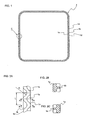
- FIG. 1 is a plan view showing a gasket in accordance with the embodiment.
- FIG. 2A is a top elevational view enlarging a portion C of the gasket shown in FIG. 1
- FIG. 2B is a cross sectional view along a line A-A
- FIG. 2C is a cross sectional view along a line B-B.
- FIG. 3A is a top elevational view of a installation groove to which a gasket in accordance with an embodiment 1 is attached
- FIG. 3B is a cross sectional view along a line D-D.
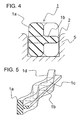
- FIG. 4 is a cross sectional view at a time of installing the gasket in accordance with the embodiment to the installation groove.
- FIG. 5 is a perspective view of a main portion of the gasket in accordance with the embodiment.
- a gasket 1 in accordance with the present embodiment is explained by exemplifying a structure used in a state of arranging two opposite surfaces comprising a surface of a resin housing in which a installation groove 2 as shown in FIG. 3 is formed, and an opposite surface of a member (not shown) opposing to the resin housing surface.
- the resin housing is formed in accordance with an injection molding, and is not worked thereafter. Accordingly, the installation groove 2 is also formed at a time of the injection molding, however, a groove flatness is bad and a tolerance is large. Further, a groove width is limited in accordance with a downsizing requirement in recent years.
- the gasket in accordance with the present invention can achieve an effect by being used in the two opposite surfaces mentioned above, however, it is not limited to such two opposite surfaces, and can be appropriately used between two opposite surface in accordance with various combinations.
- the gasket can be preferably used in a case that a installation groove is provided in the resin housing.
- the gasket 1 installed to the installation groove 2 is provided with a meandering portion 1a having a vertically long cross sectional shape in which a height is increased so as to secure a collapsing rate for absorbing a deterioration of the groove flatness and a large tolerance, a width of the gasket 1 is narrowed in correspondence to the groove width limit of the installation groove 2, and the height is larger than the width.
- the gasket is provided with the meandering portion 1a having a chamfered rectangular cross sectional shape in which a long axis is set to a direction (a groove depth direction) sandwiched by a bottom surface of the installation groove 2 provided in an opponent member 5 and an opposite surface opposing to an opponent member 5 (refer to FIGS. 2 and 4 ) .
- a cross section of the rectangular shape of the gasket 1 is formed in a symmetrical shape on the basis of a center portion in a direction of being sandwiched by the bottom surface of the installation groove 2 and the opposite surface so as to be reversibly installed.
- the gasket 1 is provided with a rib 1b provided in an inner periphery 1c and an outer periphery 1d, in a center portion in a vertical direction of a vertically long cross section of the meandering portion 1a in such a manner as to alternately protrude in the groove width direction.
- the rib 1b is provided alternately in the inner periphery 1c and the outer periphery 1d of the meandering portion 1a in such a manner that the rib 1b protrudes from the concave portion of the meandering portion 1a in a diametrical direction (the groove width direction of the gasket 1 (refer to FIGS. 2 and 5 ).
- the rib 1b is not necessarily provided in both of the inner periphery 1c and the outer periphery 1d, but may be provided in one of the inner periphery 1c and the outer periphery 1d.
- the portion protruding toward the wall surface of the installation groove 2 in the inner periphery 1c or the outer periphery 1d of the meandering portion 1a since the portion is brought into contact with the wall surface, it is possible to prevent the slant to the wall surface side.
- the portion which does not protrude toward the wall surface of the installation groove 2 in the inner periphery 1c or the outer periphery 1d of the meandering portion 1a since the corner is continuously provided, a rigidity is increased, and the gasket is hard to be collapsed. In other words, since the gasket 1 is hard to be bent in the width direction and the groove depth direction of the installation groove 2, it is possible to suppress the slant and a torsion. Further, the rigidity is increased by setting the rib 1b, and it is possible to suppress the slant and the torsion of the meandering portion 1a to the concave portion side.
- the gasket 1 in accordance with the present embodiment since it is possible to presume a buckling direction of the gasket 1, it is possible to effectively suppress the generation of the torsion of the gasket 1 at a time of compressing.
- a gasket a straight type gasket
- a cross sectional shape of the gasket is axially symmetrical, it is hard to presume which direction of an inner side or an outer side of the gasket the buckling is generated (a buckling direction).
- the gasket having the axially asymmetrical cross sectional shape it is easy to presume the buckling direction, and it is possible to increase the rigidity of the portion by setting the rib in the portion which does not protrude toward the installation groove as in the present invention so as to inhibit the buckling from being generated in the portion, whereby it is possible to inhibit the torsion from being generated.
- the cross sectional shape of the gasket 1 is formed in the chamfered rectangular cross section shown in FIG. 2 , however, is not limited to this.
- the cross sectional shape is not particularly limited as far as a vertically long cross sectional shape sandwiched by the bottom surface of the installation groove 2 and the surface opposite thereof, in addition to an oval cross section.
- the cross sectional shape is constituted by a symmetrical shape on the basis of the center portion in a direction of being sandwiched by the bottom surface of the installation groove 2 and the surface opposite thereof in such a manner as to be reversibly installed.
- the meandering shape of the gasket 1 is formed at a time of molding the gasket 1, and the gasket 1 meanders even before being installed to the installation groove 2.
- a meandering width at which the gasket 1 meanders is approximately equal to a groove width of the installation groove 2, and the present embodiment is structured such that a groove width MIN (a minimum groove width) is slightly wider than a meandering width MAX (a maximum meandering width).
- a groove width MIN a minimum groove width
- MAX a maximum meandering width
- the gasket in accordance with the present invention is not limited to the structure in which the groove width MIN (the minimum groove width) of the installation groove is slightly wider than the meandering width MAX (the maximum meandering width), but may be structured such that the groove width MIN (the minimum groove width) is equal to or slightly narrower than the meandering width MAX (the maximum meandering width). In this case, it is possible to make it hard to prevent the gasket from coming off from the installation groove.
- the gasket 1 is formed in an annular shape as a whole as shown in FIG. 1 , and has a sealed space in an inner peripheral side in a used state.
- the gasket 1 is fitted to the installation groove 2 formed in the resin housing, as shown in FIG. 2 . Further, at a time of arranging the resin housing surface to which the installation groove 2 of the resin housing is open, and the opposite surface (not shown) opposing thereto in abutting state, the protruding end portion side of the gasket 1 protruding from the installation groove 2 is compressed by the opposite surface of the member opposing to the housing surface so as to seal.
- FIGS. 2B and 2C show cross sections at different positions of the meandering portion of the gasket 1.
- FIG. 2B is a cross sectional view at a position along a line A-A in FIG. 2A , and shows a case that a left side surface of the gasket 1 is brought into contact with the installation groove 2
- FIG. 2C is a cross sectional view at a position along a line B-B in FIG. 2A .
- the gasket 1 is structured such that the cross sectional states of FIGS. 2B and 2C are formed at intervals of a predetermined distance in a circumference direction of the gasket 1, and oppose to the installation groove 2 approximately at a uniform interval one by one alternately with both side surfaces of the gasket 1.
- the gasket 1 Since the gasket 1 is meandered in the area where in which the installation groove 2 extends linearly, it is possible to arrange the gasket 1 so as to be bent within the linear installation groove 2. Accordingly, a compression resistance is improved, and it is possible to prevent the gasket 1 from falling and buckling.
- a slant preventing effect is improved by making a pitch (L in FIG. 2A) of the meandering and a magnitude of a round (R in FIG. 2A ) smaller.
- a circumference length of the gasket 1 is increased, a volume filling factor of the gasket 1 into the installation groove 2 is increased, so that it is necessary to set the volume filling factor within 100 % at the maximum.
- the meandering of the gasket 1 is formed in such a manner as to draw the circular arc, however, is not limited to this, but may be formed by bending with an angle such as a saw tooth in addition to the bending such as the circular arc.
- the kind of the meandering is not particularly limited as far as the meandering portion of the gasket 1 is formed so as to be oscillated and wind in a groove width direction of the installation groove 2.
- the gasket 1 meanders in the groove width direction in the range where the installation groove 2 extends linearly, it is possible to arrange so as to bend the gasket 1 within the linearly extending installation groove 2, it is possible to improve the compression resistance of the gasket 1, and it is possible to prevent the gasket 1 having the vertically long cross sectional shape from falling over and buckling.
Landscapes
- Engineering & Computer Science (AREA)
- General Engineering & Computer Science (AREA)
- Mechanical Engineering (AREA)
- Gasket Seals (AREA)
Claims (2)
- Dichtung (1), die in einer Installationsnut (2), die in einer von zwei gegenüberliegenden Flächen ausgebildet ist, installiert ist, und die in einer Richtung der Tiefe der Nut in einer vertikal langen Querschnittsform ausgebildet ist, mit:einem mäandernden Abschnitt (1a), der in einer Richtung der Breite der Nut mit Bezug auf die Installationsnut mäandert, wobei der mäandernde Abschnitt (1a) mäandert, bevor er in der Installationsnut (2) installiert wird, und konkave Abschnitte an einem Innenumfang (1c) und einem Außenumfang (1d) der Dichtung (1) ausbildet, gekennzeichnet durcheine Rippe (1b), die in dem Innenumfang (1c) und/oder dem Außenumfang (1d) in einem Zentralabschnitt in einer Vertikalrichtung eines vertikal langen Querschnitts des mäandernden Abschnitts (1a) vorgesehen ist, sodass sie von den konkaven Abschnitten des mäandernden Abschnitts (1a) in der Richtung der Breite der Nut vorragt.
- Dichtung (1) gemäß Anspruch 1, wobei der mäandernde Abschnitt mäandert, bevor er in der Installationsnut (2) installiert wird, und konkave Abschnitte an einem Innenumfang (1c) und einem Außenumfang (1d) der Dichtung (1) bildet, und wobei die Rippe (1b) so vorgesehen ist, dass sie von den konkaven Abschnitt an dem Innenumfang (1c) und/oder dem Außenumfang (1d) in einer Art vorragt, dass sie sich entlang der gesamten Länge der entsprechenden konkaven Abschnitte erstreckt.
Applications Claiming Priority (2)
| Application Number | Priority Date | Filing Date | Title |
|---|---|---|---|
| JP2005198669 | 2005-07-07 | ||
| PCT/JP2006/313399 WO2007007611A1 (ja) | 2005-07-07 | 2006-07-05 | ガスケット |
Publications (3)
| Publication Number | Publication Date |
|---|---|
| EP1900980A1 EP1900980A1 (de) | 2008-03-19 |
| EP1900980A4 EP1900980A4 (de) | 2012-03-14 |
| EP1900980B1 true EP1900980B1 (de) | 2013-05-01 |
Family
ID=37637005
Family Applications (1)
| Application Number | Title | Priority Date | Filing Date |
|---|---|---|---|
| EP06767905.0A Ceased EP1900980B1 (de) | 2005-07-07 | 2006-07-05 | Dichtung |
Country Status (5)
| Country | Link |
|---|---|
| US (1) | US7823888B2 (de) |
| EP (1) | EP1900980B1 (de) |
| JP (1) | JP4780108B2 (de) |
| CN (1) | CN101213390B (de) |
| WO (1) | WO2007007611A1 (de) |
Families Citing this family (15)
| Publication number | Priority date | Publication date | Assignee | Title |
|---|---|---|---|---|
| GB2460912B (en) * | 2008-06-19 | 2010-12-22 | Crane Ltd | An annular gasket |
| DE102009011413A1 (de) * | 2009-03-03 | 2010-09-16 | Neoperl Gmbh | Strahlregler |
| JP5177690B2 (ja) * | 2009-06-12 | 2013-04-03 | 日本メクトロン株式会社 | 小型電子機器用防水ガスケット |
| US20110169228A1 (en) * | 2010-01-13 | 2011-07-14 | Gm Global Technology Operations, Inc. | Sealing gasket |
| US20110298184A1 (en) * | 2010-05-07 | 2011-12-08 | Lynn Aurelius | O-Ring Apparatus With Integrated Tab and Method of Manufacturing Thereof |
| JP5660440B2 (ja) * | 2010-09-14 | 2015-01-28 | 豊和工業株式会社 | ロッドレスシリンダのシリンダガスケット |
| AT512134B1 (de) * | 2011-11-07 | 2013-08-15 | Bernecker & Rainer Ind Elektronik Gmbh | Hygienegerechtes anzeige- und bediengerät |
| JP2016052729A (ja) * | 2014-09-03 | 2016-04-14 | 小島プレス工業株式会社 | カウルルーバおよびシール材をアウトサート成形する金型 |
| FR3029257B1 (fr) * | 2014-12-02 | 2017-01-06 | Freudenberg Carl Kg | Joint d'etancheite comprenant une forme continuellement variable et des barrettes laterales de maintien |
| JP6555901B2 (ja) * | 2015-02-24 | 2019-08-07 | Nok株式会社 | 金属ガスケット |
| JP7125057B2 (ja) * | 2018-10-05 | 2022-08-24 | 内山工業株式会社 | ガスケット |
| JP7045309B2 (ja) * | 2018-12-27 | 2022-03-31 | 株式会社豊田自動織機 | 流体機械 |
| CN110159760A (zh) * | 2019-04-29 | 2019-08-23 | 海洋王照明科技股份有限公司 | 密封件、端面密封结构及灯具 |
| US11668395B2 (en) * | 2019-10-30 | 2023-06-06 | Federal-Mogul Motorparts Llc | Gasket including channel-retention features |
| JP7635472B1 (ja) * | 2023-05-19 | 2025-02-25 | Nok株式会社 | 密封構造 |
Family Cites Families (24)
| Publication number | Priority date | Publication date | Assignee | Title |
|---|---|---|---|---|
| US3163431A (en) * | 1960-06-06 | 1964-12-29 | Charles L Tanner | Seal ring means |
| US3671046A (en) * | 1970-03-03 | 1972-06-20 | Foster M Hagmann | Ring seal with special groove configuration |
| US3746348A (en) * | 1971-01-15 | 1973-07-17 | Parker Hannifin Corp | Sealing ring with retaining means |
| JPS5550362U (de) * | 1978-09-29 | 1980-04-02 | ||
| DE3225361C2 (de) * | 1982-07-07 | 1984-04-26 | Leybold-Heraeus GmbH, 5000 Köln | Verfahren zur Herstellung einer Metalldichtung für Flanschverbindungen |
| DE3703788A1 (de) * | 1987-02-07 | 1988-08-18 | Philips Patentverwaltung | Elektromagnetische dichtungsanordnung |
| FR2644217A1 (fr) * | 1989-03-07 | 1990-09-14 | Procal | Joint d'etancheite statique |
| US5076557A (en) * | 1989-11-30 | 1991-12-31 | Blackstone Corporation | Twist indicator gasket |
| JP2607441Y2 (ja) * | 1993-02-22 | 2001-09-04 | エヌオーケー株式会社 | ガスケット |
| JP3346099B2 (ja) | 1995-04-28 | 2002-11-18 | いすゞ自動車株式会社 | ガスケット |
| US5551705A (en) * | 1995-07-12 | 1996-09-03 | Fel-Pro Incorporated | Double beaded spaghetti seal with stiffness increasing deformation behavior |
| JPH09112697A (ja) * | 1995-10-17 | 1997-05-02 | Mitsubishi Electric Corp | シールリング |
| US6322087B1 (en) * | 1998-08-28 | 2001-11-27 | Perkinelmer, Inc. | Metallic seal for low load conditions |
| US6354601B1 (en) * | 1999-01-06 | 2002-03-12 | Fluoroware, Inc. | Seal for wafer containers |
| JP3349132B2 (ja) * | 1999-04-12 | 2002-11-20 | 三菱電線工業株式会社 | 低荷重シール |
| US6460859B1 (en) * | 2000-04-12 | 2002-10-08 | Parker-Hannifin Corporation | Resilient elastomer and metal retainer gasket for sealing between curved surfaces |
| US6561521B2 (en) * | 2001-03-27 | 2003-05-13 | Fmc Technologies, Inc. | Metal-to-metal seal with soft metal insert |
| US7004478B2 (en) * | 2001-12-07 | 2006-02-28 | Perkinelmer Inc. | Shallow metallic s-seal |
| CN2625659Y (zh) * | 2002-06-17 | 2004-07-14 | 樊庆铎 | 一种橡塑密封垫圈 |
| US6722660B2 (en) * | 2002-06-27 | 2004-04-20 | Federal-Mogul World Wide, Inc. | Molded gasket |
| JPWO2004007937A1 (ja) * | 2002-07-12 | 2005-11-10 | 内山工業株式会社 | ガスケット |
| JP4453279B2 (ja) * | 2003-06-26 | 2010-04-21 | Nok株式会社 | ガスケット |
| JP4577813B2 (ja) * | 2003-08-20 | 2010-11-10 | イーグル・エンジニアリング・エアロスペース株式会社 | シール装置 |
| US7316402B2 (en) * | 2006-03-09 | 2008-01-08 | United Technologies Corporation | Segmented component seal |
-
2006
- 2006-07-05 EP EP06767905.0A patent/EP1900980B1/de not_active Ceased
- 2006-07-05 US US11/988,483 patent/US7823888B2/en not_active Expired - Fee Related
- 2006-07-05 CN CN2006800236484A patent/CN101213390B/zh not_active Expired - Fee Related
- 2006-07-05 WO PCT/JP2006/313399 patent/WO2007007611A1/ja not_active Ceased
- 2006-07-05 JP JP2007524594A patent/JP4780108B2/ja not_active Expired - Fee Related
Also Published As
| Publication number | Publication date |
|---|---|
| US7823888B2 (en) | 2010-11-02 |
| CN101213390A (zh) | 2008-07-02 |
| WO2007007611A1 (ja) | 2007-01-18 |
| JPWO2007007611A1 (ja) | 2009-01-29 |
| EP1900980A1 (de) | 2008-03-19 |
| CN101213390B (zh) | 2012-05-16 |
| JP4780108B2 (ja) | 2011-09-28 |
| US20090085306A1 (en) | 2009-04-02 |
| EP1900980A4 (de) | 2012-03-14 |
Similar Documents
| Publication | Publication Date | Title |
|---|---|---|
| US7823888B2 (en) | Gasket | |
| JP5151241B2 (ja) | 密封構造 | |
| JP6255097B2 (ja) | ガスケット | |
| JP4834657B2 (ja) | ガスケットによる密封構造 | |
| EP2441987A1 (de) | Dichtung für eine kleine elektronikanwendung | |
| JP2009030773A (ja) | 密封構造 | |
| JP2006029364A (ja) | ガスケット | |
| EP3527355B1 (de) | Schweissrippenstruktur | |
| JP2009210049A (ja) | ガスケット | |
| CN203570455U (zh) | 气缸盖罩密封条 | |
| US10741816B2 (en) | Battery module | |
| US20150136575A1 (en) | Rotary Knob | |
| JP4453279B2 (ja) | ガスケット | |
| WO1998023821A1 (en) | Concrete block having cover plate | |
| JP4573021B2 (ja) | 燃料電池用ガスケット | |
| JP4760619B2 (ja) | カバー部材の構造 | |
| US7608955B2 (en) | Motor | |
| JP3184486B2 (ja) | 蓋板を備えたコンクリートブロック | |
| JP2006200649A (ja) | 密封構造及びガスケット用装着溝 | |
| CN219421247U (zh) | 卡扣结构及智能面板 | |
| JP2003240122A (ja) | ガスケット取付構造 | |
| JP5056724B2 (ja) | ガスケット | |
| JP4989426B2 (ja) | 空調用ダクト | |
| WO2024166978A1 (ja) | ガスケットおよび密封構造 | |
| JP3146298B2 (ja) | プレート式熱交換器用ガスケット |
Legal Events
| Date | Code | Title | Description |
|---|---|---|---|
| PUAI | Public reference made under article 153(3) epc to a published international application that has entered the european phase |
Free format text: ORIGINAL CODE: 0009012 |
|
| 17P | Request for examination filed |
Effective date: 20071206 |
|
| AK | Designated contracting states |
Kind code of ref document: A1 Designated state(s): DE GB |
|
| DAX | Request for extension of the european patent (deleted) | ||
| RBV | Designated contracting states (corrected) |
Designated state(s): DE GB |
|
| A4 | Supplementary search report drawn up and despatched |
Effective date: 20120215 |
|
| RIC1 | Information provided on ipc code assigned before grant |
Ipc: F16J 15/10 20060101AFI20120209BHEP |
|
| 17Q | First examination report despatched |
Effective date: 20120509 |
|
| DAX | Request for extension of the european patent (deleted) | ||
| GRAP | Despatch of communication of intention to grant a patent |
Free format text: ORIGINAL CODE: EPIDOSNIGR1 |
|
| RIN1 | Information on inventor provided before grant (corrected) |
Inventor name: HAYASHI, EIZO C/O NOK CORPORATION 609, |
|
| GRAS | Grant fee paid |
Free format text: ORIGINAL CODE: EPIDOSNIGR3 |
|
| GRAA | (expected) grant |
Free format text: ORIGINAL CODE: 0009210 |
|
| AK | Designated contracting states |
Kind code of ref document: B1 Designated state(s): DE GB |
|
| REG | Reference to a national code |
Ref country code: GB Ref legal event code: FG4D |
|
| REG | Reference to a national code |
Ref country code: DE Ref legal event code: R096 Ref document number: 602006036049 Country of ref document: DE Effective date: 20130627 |
|
| PLBE | No opposition filed within time limit |
Free format text: ORIGINAL CODE: 0009261 |
|
| STAA | Information on the status of an ep patent application or granted ep patent |
Free format text: STATUS: NO OPPOSITION FILED WITHIN TIME LIMIT |
|
| 26N | No opposition filed |
Effective date: 20140204 |
|
| REG | Reference to a national code |
Ref country code: DE Ref legal event code: R097 Ref document number: 602006036049 Country of ref document: DE Effective date: 20140204 |
|
| PGFP | Annual fee paid to national office [announced via postgrant information from national office to epo] |
Ref country code: GB Payment date: 20200624 Year of fee payment: 15 |
|
| PGFP | Annual fee paid to national office [announced via postgrant information from national office to epo] |
Ref country code: DE Payment date: 20200624 Year of fee payment: 15 |
|
| REG | Reference to a national code |
Ref country code: DE Ref legal event code: R119 Ref document number: 602006036049 Country of ref document: DE |
|
| GBPC | Gb: european patent ceased through non-payment of renewal fee |
Effective date: 20210705 |
|
| PG25 | Lapsed in a contracting state [announced via postgrant information from national office to epo] |
Ref country code: GB Free format text: LAPSE BECAUSE OF NON-PAYMENT OF DUE FEES Effective date: 20210705 Ref country code: DE Free format text: LAPSE BECAUSE OF NON-PAYMENT OF DUE FEES Effective date: 20220201 |