EP1898172A2 - Grosskalibriges Marine-Geschütz - Google Patents
Grosskalibriges Marine-Geschütz Download PDFInfo
- Publication number
- EP1898172A2 EP1898172A2 EP07016692A EP07016692A EP1898172A2 EP 1898172 A2 EP1898172 A2 EP 1898172A2 EP 07016692 A EP07016692 A EP 07016692A EP 07016692 A EP07016692 A EP 07016692A EP 1898172 A2 EP1898172 A2 EP 1898172A2
- Authority
- EP
- European Patent Office
- Prior art keywords
- projectile
- magazine
- tower
- basket area
- gun according
- Prior art date
- Legal status (The legal status is an assumption and is not a legal conclusion. Google has not performed a legal analysis and makes no representation as to the accuracy of the status listed.)
- Granted
Links
Images

Classifications
-
- F—MECHANICAL ENGINEERING; LIGHTING; HEATING; WEAPONS; BLASTING
- F41—WEAPONS
- F41A—FUNCTIONAL FEATURES OR DETAILS COMMON TO BOTH SMALLARMS AND ORDNANCE, e.g. CANNONS; MOUNTINGS FOR SMALLARMS OR ORDNANCE
- F41A23/00—Gun mountings, e.g. on vehicles; Disposition of guns on vehicles
- F41A23/24—Turret gun mountings
-
- B—PERFORMING OPERATIONS; TRANSPORTING
- B63—SHIPS OR OTHER WATERBORNE VESSELS; RELATED EQUIPMENT
- B63B—SHIPS OR OTHER WATERBORNE VESSELS; EQUIPMENT FOR SHIPPING
- B63B3/00—Hulls characterised by their structure or component parts
- B63B3/14—Hull parts
- B63B3/70—Reinforcements for carrying localised loads, e.g. propulsion plant, guns
-
- B—PERFORMING OPERATIONS; TRANSPORTING
- B63—SHIPS OR OTHER WATERBORNE VESSELS; RELATED EQUIPMENT
- B63G—OFFENSIVE OR DEFENSIVE ARRANGEMENTS ON VESSELS; MINE-LAYING; MINE-SWEEPING; SUBMARINES; AIRCRAFT CARRIERS
- B63G3/00—Arrangements of ammunition stores or handlers; Vessels characterised thereby
- B63G3/04—Arrangements of ammunition stores or handlers; Vessels characterised thereby for missiles
-
- F—MECHANICAL ENGINEERING; LIGHTING; HEATING; WEAPONS; BLASTING
- F41—WEAPONS
- F41A—FUNCTIONAL FEATURES OR DETAILS COMMON TO BOTH SMALLARMS AND ORDNANCE, e.g. CANNONS; MOUNTINGS FOR SMALLARMS OR ORDNANCE
- F41A9/00—Feeding or loading of ammunition; Magazines; Guiding means for the extracting of cartridges
- F41A9/01—Feeding of unbelted ammunition
- F41A9/04—Feeding of unbelted ammunition using endless-chain belts carrying a plurality of ammunition
-
- F—MECHANICAL ENGINEERING; LIGHTING; HEATING; WEAPONS; BLASTING
- F41—WEAPONS
- F41A—FUNCTIONAL FEATURES OR DETAILS COMMON TO BOTH SMALLARMS AND ORDNANCE, e.g. CANNONS; MOUNTINGS FOR SMALLARMS OR ORDNANCE
- F41A9/00—Feeding or loading of ammunition; Magazines; Guiding means for the extracting of cartridges
- F41A9/61—Magazines
- F41A9/64—Magazines for unbelted ammunition
- F41A9/76—Magazines having an endless-chain conveyor
Definitions
- the invention relates to an integrated into a military ship, large caliber gun, which is constructed with the tower and the weapon system of a Panzerhaubitze, with the features of the preamble of claim 1.
- the invention has the object of providing a built-in military ship, large-caliber gun with the features of the preamble of claim 1 so that a fully automatic transport of bullets from a bullet magazine to the area behind the weapon is possible, the arrangement should be constructed as space-saving and a rapid and smooth Munitionsfluß should be achieved.
- a basic idea of the invention is to adopt a number of features which are known from the above-referenced howitzer, even in a gun integrated into a military ship, but to supplement it with further features and to adapt them overall so that one for the application on a ship optimized total solution is obtained.
- the projectile magazine is placed much lower than is the case with the known Panzerhaubitze, namely below the tower basket area.
- the projectile feeding device known Panzerhaubitze namely the pivotable about a horizontal axis ready shell, in which the projectiles are inserted from the projectile transporter and from which they are transferred directly into the loading tray of the projectile transfer arm.
- the projectiles are rather from the projectile transporter Projectile hoist fed by which they are conveyed from the lower floor projectile magazine in the tower basket area and there introduced directly into the loading tray of the lowered Geschoßübergabearms.
- the entire projectile transport from the bullet magazine to the loading position can be done automatically, controlled by known electronic control devices.
- the position coordinates of the projectiles in the projectile magazine and further projectile data can be stored in an ammunition flow logic, so that the positions of predefined projectiles can already be selected when the projectile transporter is actuated.
- Fig. 1 shows a highly schematic representation of a part of the hull FR of a military ship, such as a frigate, with a ship's deck D, integrated into the hull, large caliber gun GT, which is constructed with the tower and the weapon system of a tank howitzer, and Other facilities such as a Artillerieraketenabschußvorraum AR and a tracking device RA.
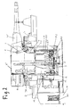
- Fig. 2 shows the integrated into the hull gun in a more detailed representation.
- the turret GT of the gun On the upper deck D of the hull the turret GT of the gun is arranged and connected via a shock-absorbing storage L with the hull.
- This known storage L is not closer in the following explained and reference is made to the cited references.
- the tower GT which can be directed in elevation weapon W is arranged on the trunnion 1 in a known manner a projectile transfer arm 2 is pivotally mounted, at the free end of a charging tray 3 is arranged.
- the arrangement is such that, in a manner not shown raised Geschoßübergabearm 2, the charging tray 3 is aligned with the Rohrselelenachse of the weapon, while in the lowered state of the Geschoßübergabearms 2, as shown in Fig. 2, the charging tray 3 perpendicular to the ground of the arranged below the tower GT tower basket area TK is aligned.
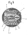
- a projectile magazine 4 is arranged, in which generally projected reference numeral 5 projectiles are arranged vertically standing to the magazine floor in such a way that, as shown in FIG. 4, between the aligned in substantially radial rows 5 a passage space 4.1 is released.
- a projectile transporter 6 is arranged, which has a at least about a vertical axis pivotable transport arm 6.1, at the end of a pivotable gripping device is arranged 6.2.
- Such a projectile transporter is known per se and, for example, in EP 0 331 980 A1 described.
- a projectile lift 7 is present, starting in the direction perpendicular to the magazine floor from the projectile magazine 4, in the tower basket area TK hineinerstreckt.
- This projectile hoisting elevator 7 has a conveying element 7.1 designed as a back-rigid chain, on which a lifting plate is arranged, which is designated by 7.2 in FIG.
- the lifting plate 7.2 is moved by means of the driven by a drive motor 7.3 conveying element 7.1 in a direction perpendicular to the magazine floor upwards and back again.
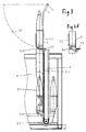
- FIGs 3 and 3 A The more precise operation of the projectile lift 7 can be seen in Figures 3 and 3 A.
- Figures 3 and 3 A different phases in the operation of the floor conveyor elevator 7 in conjunction with the charging tray 3 of the projectile transfer arm 2 are shown simultaneously.
- the lifting plate is 7.2 7.2 in Fig. 3 in its lower position within the projectile magazine 4 with 7.21, while it is designated in its upper position within the tower basket area TK with 7.22.
- the lifting plate 7.21 In the lower position of the lifting plate 7.21 is placed on this a projectile 5.1, which is conveyed by means of the projectile hoist elevator upwards and inserted into the charging tray 3 of the projectile transfer arm 2. In the upper position, in which the lifting plate is denoted by 7.22, the projectile carries the reference number 5.2.
- the charging tray 3 is arranged in alignment with the direction of movement of the lifting plate 7.21 or 7.22.
- the lifting plate 7.21 or 7.22 of the projectile lift 7 is designed as a first half-plate on which the projectile 5.1 or 5.2 is supported with a portion of the basement floor.
- the charging tray 3 has as a projectile holding device a substantially complementary to the designed as a first half disc hub plate formed second half plate 3.1, which is pivotable about a parallel to the longitudinal axis of the loading tray pivot axis from an open position shown in Fig. 3 A in a closed position shown in FIG , In the open position, the projectile 5.2 is supported only by the lifting plate 7.22 at its bottom. In this position, the projectile 5.2 can be freely introduced into the charging cradle 3 in the course of its upward movement.
- the half-plate 3.1 pivots the projectile holding device from the open position (Fig. 3 A) in the closed position (Fig. 3).
- the projectile 5.2 is supported both by the lifting plate 7.22, as well as by the half-plate 3.1 of the projectile holding device on the ground.
- the lifting plate can now be moved back down while the projectile 5.2 is held in the charging tray 3.
- the projectile transfer arm 2 can be pivoted about the trunnion axis 1 in the direction of 1.1 upwards into the position, not shown, behind the weapon, in which the longitudinal axis of the charging cradle 3 is aligned with the tube axis of the weapon W.
- the feeding of the projectile 5.1 which is located in the lower position Hubteller 7.2, takes place in a conventional manner by the Projectile transporter 6 (FIG. 4) grips one of the projectiles 5 from the projectile magazine 4 by means of the gripping device 6.2, moves it in the direction of the projectile-conveying elevator 7 and places it on the lifting plate 7.21 in the lower position.
- amaschineladungsföder worn 8 is further provided, which extends parallel to the projectile hoist elevator 7 in the direction perpendicular to the magazine floor from the projectile magazine 4, starting in the tower basket area TK inside. Through them, propellant charges arranged in an additional propellant charge magazine arranged below the tower basket area can be conveyed into the tower basket area.
- propellant charges can be stored in a propellant charge magazine 10 arranged on the tower GT.
- a loading device 9 is additionally arranged, fed by means of the projectiles from the side of the projectile magazine 4, or can be discharged from it.
- the bullets 4 to be supplied to the projectile magazine 4 are conveyed from an ammunition bunker (not shown) arranged on a lower level of the ship to the level of the projectile magazine 4 by means of an ammunition elevator 11 (FIG. 2). They are arranged on a carriage 11.1, which is zubewegbar on a guideway 11.2 on the projectile magazine 4.
- the projectiles are then removed by an operator from the carriage 11.1 by means of a projectile gripper 13, which is arranged on a process device with lifting device 12 and by means of the latter in the direction of arrow P of the loading device 9, from which they are removed by means of the projectile transporter 6 and their parking spaces in the projectile magazine 4 are supplied.
- a discharge of the projectile magazine 4 is possible in reverse order of operations.
- the traversing device is provided with lifting device 12 with a brake lever 12.1, by which they and the projectile are held instantaneously when about the operator B releases the manually operable projectile gripper device 13 as a result of a ship movement.
Landscapes
- Engineering & Computer Science (AREA)
- General Engineering & Computer Science (AREA)
- Aviation & Aerospace Engineering (AREA)
- Chemical & Material Sciences (AREA)
- Combustion & Propulsion (AREA)
- Mechanical Engineering (AREA)
- Ocean & Marine Engineering (AREA)
- Aiming, Guidance, Guns With A Light Source, Armor, Camouflage, And Targets (AREA)
- Ship Loading And Unloading (AREA)
- Warehouses Or Storage Devices (AREA)
- Toys (AREA)
- Vibration Dampers (AREA)
- Fittings On The Vehicle Exterior For Carrying Loads, And Devices For Holding Or Mounting Articles (AREA)
- Intermediate Stations On Conveyors (AREA)
Abstract
Description
- Die Erfindung betrifft ein in ein militärisches Schiff integriertes, großkalibriges Geschütz, das mit dem Turm und der Waffenanlage einer Panzerhaubitze aufgebaut ist, mit den Merkmalen aus dem Oberbegriff des Patentanspruchs 1.
- Eine derartige Anordnung ist bekannt und beispielsweise in
DE 10 254 786 A1 undWO 2004/048878 A1 beschrieben.
Eine bekannte Panzerhaubitze ist inEP 0 331 980 A1 beschrieben. - Der Erfindung liegt die Aufgabe zugrunde, ein in ein militärisches Schiff integriertes, großkalibriges Geschütz mit den Merkmalen aus dem Oberbegriff des Patentanspruchs 1 so weiterzubilden, dass ein vollautomatischer Transport der Geschosse aus einem Geschoßmagazin bis in den Bereich hinter der Waffe möglich ist, wobei die Anordnung möglichst platzsparend aufgebaut sein und ein möglichst rascher und reibungsloser Munitionsfluß erreicht werden sollte.
- Die Lösung dieser Aufgabe geschieht erfindungsgemäß mit der Merkmalskombination aus dem kennzeichnenden Teil von Patentanspruch 1. Vorteilhafte Weiterbildungen der Erfindung sind in den abhängigen Ansprüchen beschrieben.
- Ein Grundgedanke der Erfindung besteht darin, eine Reihe von Merkmalen, die aus der oben zitierten Panzerhaubitze bekannt sind, auch bei einem in ein militärisches Schiff integriertem Geschütz zu übernehmen, sie aber durch weitere Merkmale zu ergänzen und insgesamt so anzupassen, dass eine für die Anwendung auf einem Schiff optimalisierte Gesamtlösung erhalten wird.
- Aus Gründen der besonderen Raumverhältnisse auf einem Schiff wird das Geschoßmagazin wesentlich tiefer angeordnet, als dies bei der bekannten Panzerhaubitze der Fall ist, nämlich unterhalb des Turmkorbbereiches. Aus diesem Grunde entfallen auch einige Merkmale der Geschoßzuführungsvorrichtung der bekannten Panzerhaubitze, nämlich die um eine horizontale Achse hochschwenkbare Bereitschaftsschale, in welche die Geschosse vom Geschoßtransporter eingelegt werden und von der aus sie direkt in die Ladeschale des Geschoßübergabearms überführt werden. Bei der erfindungsgemäßen Lösung werden die Geschosse vielmehr vom Geschoßtransporter einem Geschoßförderaufzug zugeführt, durch den sie von dem tiefer liegenden Geschoßmagazin in den Turmkorbbereich hineinbefördert und dort direkt in die Ladeschale des herabgeschwenkten Geschoßübergabearms eingeführt werden. Auf diese Weise läßt sich ein sehr rascher und reibungsloser, vollautomatischer Transport der Geschosse vom Geschoßmagazin in den Bereich hinter der Waffe erreichen. Der gesamte Geschoßtransport aus dem Geschoßmagazin bis in die Ladeposition kann automatisch erfolgen, gesteuert von an sich bekannten elektronischen Steuereinrichtungen. In an sich bekannter Weise können hierbei beispielsweise die Lagekoordinaten der Geschosse im Geschoßmagazin und weitere Geschoßdaten in einer Munitionsfluß-Logik abgespeichert sein, so dass bereits bei Betätigung des Geschoßtransporters die Positionen vorgegebener Geschosse angewählt werden können.
- Im folgenden wird anhand der beigefügten Zeichnungen ein Ausführungsbeispiel für ein in ein militärisches Schiff integriertes, großkalibriges Geschütz nach der Erfindung und der Ablauf der Zuführung der Geschosse aus dem Geschoßmagazin in die Ladeposition näher erläutert.
- In den Zeichnungen zeigen:
- Fig. 1
- in einer stark schematisierten Darstellung einen Teil eines militärischen Schiffes im Längsschnitt mit einem in das Schiff integrierten, großkalibrigen Geschütz;
- Fig. 2
- im gegenüber Fig. 1 vergrößerten Längsschnitt das Geschütz nach Fig. 1;
- Fig. 3
- in gegenüber Fig. 2 noch einmal vergrößerter Teildarstellung die Ladeschale und den Geschoßförderaufzug des Geschützes nach Fig. 2;
- Fig. 3 A
- in einer Darstellung analog Fig. 3 einen Teil der Ladeschale und des Geschoßförderaufzuges in einer gegenüber Fig. 3 veränderten Phase des Geschoßzuführungsvorgangs;
- Fig. 4
- in Aufsicht auf das Geschoßmagazin des Geschützes nach Fig. 2.
- Fig. 1 zeigt in einer stark schematisierten Darstellung einen Teil des Schiffskörpers FR eines militärischen Schiffes, beispielsweise einer Fregatte, mit einem Schiffsdeck D, einem in den Schiffskörper integrierten, großkalibrigen Geschütz GT, das mit dem Turm und der Waffenanlage einer Panzerhaubitze aufgebaut ist, sowie weiteren Einrichtungen wie beispielsweise einer Artillerieraketenabschußvorrichtung AR und einem Ortungsgerät RA.
- Fig. 2 zeigt das in den Schiffskörper integrierte Geschütz in einer detaillierteren Darstellung.
Auf dem Oberdeck D des Schiffskörpers ist der Turm GT des Geschützes angeordnet und über eine stoßdämpfende Lagerung L mit dem Schiffskörper verbunden. Diese an sich bekannte Lagerung L wird im folgenden nicht näher erläutert und es wird hierzu auf die eingangs zitierten Druckschriften verwiesen. Im Turm GT ist die in Elevation richtbare Waffe W angeordnet, an deren Schildzapfen 1 in bekannter Weise ein Geschoßübergabearm 2 schwenkbar gelagert ist, an dessen freiem Ende eine Ladeschale 3 angeordnet ist. Die Anordnung ist derart, dass sich, bei in nicht dargestellter Weise angehobenem Geschoßübergabearm 2, die Ladeschale 3 fluchtend zur Rohrseelenachse der Waffe steht, während im herabgeschwenkten Zustand des Geschoßübergabearms 2, wie er in Fig. 2 dargestellt ist, die Ladeschale 3 senkrecht zum Boden des unterhalb des Turmes GT angeordneten Turmkorbbereiches TK ausgerichtet ist. - Unterhalb des Turmkorbbereiches TK ist ein Geschoßmagazin 4 angeordnet, in welchem allgemein mit Bezugsziffer 5 versehene Geschosse senkrecht zum Magazinboden stehend angeordnet sind und zwar so, dass, wie Fig. 4 zu entnehmen, zwischen den in im wesentlichen radialen Reihen ausgerichteten Geschossen 5 ein Durchgangsraum 4.1 freigelassen ist.
In diesem Durchgangsraum 4.1 ist ein Geschoßtransporter 6 angeordnet, der einen mindestens um eine Vertikalachse schwenkbaren Transportarm 6.1 aufweist, an dessen Ende eine schwenkbare Greifvorrichtung 6.2 angeordnet ist. Ein derartiger Geschoßtransporter ist an sich bekannt und beispielsweise inEP 0 331 980 A1 beschrieben. - Um einen reibungslosen Munitionsfluß von diesem tiefer gelegten Geschoßmagazin 4 in den Bereich hinter der Waffe W zu ermöglichen, ist ein Geschoßförderaufzug 7 vorhanden, der sich in senkrechter Richtung zum Magazinboden vom Geschoßmagazin 4 ausgehend, in den Turmkorbbereich
TK hineinerstreckt. Dieser Geschoßförderaufzug 7 besitzt ein als rückensteife Kette ausgebildetes Förderelement 7.1, an dem ein Hubteller angeordnet ist, der in Fig. 2 mit 7.2 bezeichnet ist. Der Hubteller 7.2 ist mittels des von einem Antriebsmotor 7.3 angetriebenen Förderelementes 7.1 in einer Richtung senkrecht zum Magazinboden nach oben und wieder zurück bewegbar. - Die genauere Funktionsweise des Geschoßförderaufzugs 7 ist den Figuren 3 und 3 A zu entnehmen. In den Figuren 3 und 3 A sind verschiedene Phasen in der Funktionsweise des Geschoßförderaufzugs 7 in Verbindung mit der Ladeschale 3 des Geschoßübergabearms 2 gleichzeitig dargestellt. So ist der Hubteller 7.2 in Fig. 3 in seiner unteren Stellung innerhalb des Geschoßmagazins 4 mit 7.21 bezeichnet, während er in seiner oberen Stellung innerhalb des Turmkorbbereiches TK mit 7.22 bezeichnet ist.
- In der unteren Stellung des Hubtellers 7.21 ist auf diesen ein Geschoß 5.1 aufgesetzt, das mittels des Geschoßförderaufzuges nach oben gefördert und in die Ladeschale 3 des Geschoßübergabearms 2 eingeführt wird. In der oberen Position, in welcher der Hubteller mit 7.22 bezeichnet ist, trägt das Geschoß die Bezugsziffer 5.2.
- In der herabgeschwenkten Stellung des Geschoßübergabearms 2 ist die Ladeschale 3 fluchtend zur Bewegungsrichtung des Hubtellers 7.21 beziehungsweise 7.22 angeordnet.
- Im folgenden wird die genauere Ausbildung der Ladeschale 3 und des Hubtellers 7.21 beziehungsweise 7.22 beschrieben, durch welche die Förderung des Geschosses in die Ladeschale 3 und das Festhalten des Geschosses in der Ladeschale 3 zum weiteren Hochschwenken in den Bereich hinter der Waffe ermöglicht wird.
- Der Hubteller 7.21 beziehungsweise 7.22 des Geschoßförderaufzugs 7 ist als ein erster Halbteller ausgebildet, auf dem sich das Geschoß 5.1 beziehungsweise 5.2 mit einem Teil des Geschoßbodens abstützt. Die Ladeschale 3 besitzt als Geschoßhaltevorrichtung einen im wesentlichen komplementär zum als erster Halbteller gestalteten Hubteller ausgebildeten zweiten Halbteller 3.1, der um eine parallel zur Längsachse der Ladeschale verlaufende Schwenkachse aus einer in Fig. 3 A dargestellten Offenstellung in eine in Fig. 3 dargestellte Geschlossenstellung verschwenkbar ist. In der Offenstellung ist das Geschoß 5.2 lediglich vom Hubteller 7.22 an seinem Boden abgestützt. In dieser Stellung kann das Geschoß 5.2 im Zuge seiner Aufwärtsbewegung unbehindert in die Ladeschale 3 eingeführt werden. Sobald sich das Geschoß 5.2 in der Ladeschale 3 befindet, schwenkt der Halbteller 3.1 der Geschoßhaltevorrichtung aus der Offenstellung (Fig. 3 A) in die Geschlossenstellung (Fig. 3). In dieser Stellung ist das Geschoß 5.2 sowohl durch den Hubteller 7.22, als auch durch den Halbteller 3.1 der Geschoßhaltevorrichtung am Boden abgestützt. Der Hubteller kann nunmehr nach unten zurückgefahren werden, während das Geschoß 5.2 in der Ladeschale 3 festgehalten wird. Nun kann der Geschoßübergabearm 2 um die Schildzapfenachse 1 in Richtung 1.1 nach oben geschwenkt werden in die nicht dargestellte Position hinter der Waffe, in welcher die Längsachse der Ladeschale 3 fluchtend zur Rohrseelenachse der Waffe W steht.
- Die Zuführung des Geschosses 5.1, zu dem sich in der unteren Stellung befindenden Hubteller 7.2, erfolgt in an sich bekannter Weise, indem der Geschoßtransporter 6 (Fig. 4) mittels der Greifvorrichtung 6.2 eines der Geschosse 5 aus dem Geschoßmagazin 4 ergreift, es in Richtung auf den Geschoßförderaufzug 7 bewegt und auf den Hubteller 7.21 in der unteren Position aufsetzt.
- Im dargestellten Ausführungsbeispiel ist weiterhin eine Treibladungsfödereinrichtung 8 vorgesehen, die sich parallel zum Geschoßförderaufzug 7 in senkrechter Richtung zum Magazinboden vom Geschoßmagazin 4 ausgehend in den Turmkorbbereich TK hinein erstreckt. Durch sie können in einem unterhalb des Turmkorbbereiches angeordneten zusätzlichen Treibladungsmagazin angeordnete Treibladungen in den Turmkorbbereich gefördert werden.
- Weiterhin können Treibladungen in einem am Turm GT angeordneten Treibladungsmagazin 10 gelagert sein.
- Im Geschoßmagazin 4 ist zusätzlich eine Beladeeinrichtung 9 angeordnet, mittels der Geschosse von der Seite her dem Geschoßmagazin 4 zugeführt, oder vom ihm abgeführt werden können.
- Die dem Geschoßmagazin 4 zuzuführenden Geschosse werden aus einem nicht dargestellten, auf einer tieferen Ebene des Schiffes angeordneten Munitionsbunker mittels eines Munitionsaufzugs 11 (Fig. 2) auf die Ebene des Geschoßmagazins 4 befördert. Sie sind auf einem Wagen 11.1 angeordnet, der auf einer Führungsbahn 11.2 auf das Geschoßmagazin 4 zubewegbar ist. Die Geschosse werden dann von einer Bedienungsperson vom Wagen 11.1 mittels einer Geschoßgreifvorrichtung 13 abgenommen, die an einer Verfahrenseinrichtung mit Hubeinrichtung 12 angeordnet ist und mittels letzterer in Pfeilrichtung P der Beladeeinrichtung 9 zugeführt, von der sie mittels des Geschoßtransporters 6 abgenommen und ihren Abstellplätzen im Geschoßmagazin 4 zugeführt werden. Ein Entladen des Geschoßmagazins 4 ist in umgekehrter Reihenfolge der Vorgänge möglich.
Da bei allen Greif- und Umladungsvorgängen unvorhergesehene Bewegungen des Schiffes auftreten können, muß dafür gesorgt werden, dass insbesondere die ein hohes Gewicht aufweisenden Geschosse nicht in eine unkontrollierte Bewegung geraten können. Aus diesem Grunde ist die Verfahreinrichtung mit Hubeinrichtung 12 mit einem Bremshebel 12.1 versehen, durch welche sie und das Geschoß augenblicklich festgehalten werden, wenn etwa die Bedienungsperson B infolge einer Schiffsbewegung die manuell betätigbare Geschoßgreifvorrichtung 13 losläßt.
Claims (7)
- In ein militärisches Schiff integriertes, großkalibriges Geschütz, das mit dem Turm und der Waffenanlage einer Panzerhaubitze aufgebaut ist, wobei der in Azimut schwenbare Turm, in dem die in Elevation richtbare Waffe angeordnet ist, über eine stoßdämpfende Lagerung mit dem Schiffskörper verbunden ist und unter dem Turm ein Turmkorbbereich angeordnet ist, in welchen ein am Schildzapfen der Waffe schwenkbar gelagerter Geschoßübergabearm herabschwenkbar ist, an dessen freiem Ende eine Ladeschale derart angeordnet ist, dass sie in der angehobenen Stellung des Geschoßübergabearms fluchtend zur Rohrseelenachse der Waffe steht, gekennzeichnet durch folgende Merkmale:a)
Unterhalb des Turmkorbbereiches (TK) ist ein Geschoßmagazin (4) angeordnet, in welchem die Geschosse (5) senkrecht zum Magazinboden stehend unter Freilassung eines Durchgangsraums (4.1) gelagert sind;b)
in dem Durchgangsraum (4.1) ist ein Geschoßtransporter (6) angeordnet, der einen mindestens um eine Vertikalachse schwenkbaren Transportarm (6.1) aufweist, an dessen Ende eine schwenkbare Greifvorrichtung (6.2) angeordnet ist;c)
es ist ein Geschoßförderaufzug (7) vorhanden, der sich in senkrechter Richtung zum Magazinboden vom Geschoßmagazin (4) ausgehend in den Turmkorbbereich (TK) hinein erstreckt und mindestens einen an einem motorisch angetriebenen Förderelement (7.1) angeordneten, senkrecht zum Magazinboden bewegbaren Hubteller (7.2) zur Aufnahme eines vom Geschoßtransporter (6) herangeführten Geschosses (5.1) aufweist;d)
Geschoßübergabearm (2) und Geschoßförderaufzug (7) sind so zueinander angeordnet, dass bei in den Turmkorbbereich (TK) herabgeschwenktern Geschoßübergabearm (2) die Ladeschale (3) fluchtend zur Bewegungsrichtung des Hubtellers (7.21-7.22) des Geschoßförderaufzugs (7) angeordnet ist derart, dass ein auf dem Hubteller (7.22) angeordnetes Geschoß (5.2) unmittelbar in die mit einer Geschoßhaltevorrichtung (3.1) versehene Ladeschale (3) einführbar ist;e)
es sind Antriebs- und Steuereinrichtungen zur Bewegung des Geschoßtransporters (6) des Geschoßförderaufzugs (7) und des Geschoßübergabearms (2) vorhanden. - Geschütz nach Anspruch 1, dadurch gekennzeichnet, dass das Förderelement (7.1) als rückensteife Kette ausgebildet ist.
- Geschütz nach Anspruch 1 oder 2, dadurch gekennzeichnet, dass der Hubteller (7.21-7.22) des Geschoßförderaufzugs (7) als erster Halbteller ausgebildet ist und die Ladeschale (3) am hinteren Ende als Geschoßhaltevorrichtung (3.1) einen im wesentlichen komplementär zum ersten Halbteller ausgebildeten zweiten Halbteller aufweist, der aus einer Offenstellung (Fig. 3 A), in der das Geschoß (5.2) in die Ladeschale (3) einführbar ist, in eine Geschlossenstellung (Fig. 3) verschwenkbar ist, in der er hinter den Boden des Geschosses (5.2) in den vom Hubteller (7.22) freigelassenen Bereich einschwenkt.
- Geschütz nach Anspruch 3, dadurch gekennzeichnet, dass der zweite Halbteller der Geschoßhaltevorrichtung (3.1) um eine parallel zur Längsachse der Ladeschale (3) verlaufende Schwenkachse aus der Offenstellung in die Geschlossenstellung verschwenkbar ist.
- Geschütz nach einem der Ansprüche 1 bis 4, dadurch gekennzeichnet, dass an der Ladeschale (3) eine Geschoßansetzvorrichtung angeordnet ist.
- Geschütz nach einem der Ansprüche 1 bis 5, dadurch gekennzeichnet, dass unterhalb des Turmkorbbereiches (TK) zusätzlich ein Treibladungsmagazin angeordnet ist und eine Treibladungsfördereinrichtung (8) vorgesehen ist, die sich in senkrechter Richtung zum Magazinboden vom Geschoßmagazin (4) ausgehend in den Turmkorbbereich (TK) hinein erstreckt.
- Geschütz nach einem der Ansprüche 1 bis 6, dadurch gekennzeichnet, dass innerhalb des Geschoßmagazins (4) eine Beladeeinrichtung (9) für das Geschoßmagazin angeordnet ist.
Applications Claiming Priority (1)
| Application Number | Priority Date | Filing Date | Title |
|---|---|---|---|
| DE102006041602A DE102006041602B8 (de) | 2006-09-05 | 2006-09-05 | In ein militärisches Schiff integriertes, großkalibriges Geschütz |
Publications (3)
| Publication Number | Publication Date |
|---|---|
| EP1898172A2 true EP1898172A2 (de) | 2008-03-12 |
| EP1898172A3 EP1898172A3 (de) | 2010-06-09 |
| EP1898172B1 EP1898172B1 (de) | 2011-10-19 |
Family
ID=38477372
Family Applications (1)
| Application Number | Title | Priority Date | Filing Date |
|---|---|---|---|
| EP07016692A Not-in-force EP1898172B1 (de) | 2006-09-05 | 2007-08-25 | Grosskalibriges Marine-Geschütz |
Country Status (5)
| Country | Link |
|---|---|
| US (1) | US7849782B2 (de) |
| EP (1) | EP1898172B1 (de) |
| AT (1) | ATE529718T1 (de) |
| DE (1) | DE102006041602B8 (de) |
| ES (1) | ES2374575T3 (de) |
Cited By (2)
| Publication number | Priority date | Publication date | Assignee | Title |
|---|---|---|---|---|
| ITTO20100370A1 (it) * | 2010-05-03 | 2011-11-04 | Oto Melara Spa | Sistema di movimentazione per oggetti in un magazzino. |
| WO2012097806A1 (de) | 2011-01-20 | 2012-07-26 | Krauss-Maffei Wegmann Gmbh & Co. Kg | Munitionslift zum aufmunitionieren eines waffenturms, waffenturm sowie verfahren zum aufmunitionieren eines waffenturms |
Families Citing this family (4)
| Publication number | Priority date | Publication date | Assignee | Title |
|---|---|---|---|---|
| FR2933373B1 (fr) * | 2008-07-03 | 2010-08-20 | Dcns | Principe d'integration, contre menaces asymetriques, de systemes d'armes missiles sur rampe fixe pour batiment de surface furtifs |
| US8701561B2 (en) * | 2010-09-13 | 2014-04-22 | Raytheon Company | Projectile that includes a sensor to obtain environmental data during launch from a cannon |
| KR102405425B1 (ko) | 2015-12-17 | 2022-06-08 | 한화디펜스 주식회사 | 포탄 및 장약을 위한 복합장전장치 및 복합장전방법 |
| SE541259C2 (sv) | 2016-06-21 | 2019-05-21 | Bae Systems Bofors Ab | System och förfarande för påfyllning av ammunition till ett primärmagasin i en automatkanon |
Citations (2)
| Publication number | Priority date | Publication date | Assignee | Title |
|---|---|---|---|---|
| EP0331980A1 (de) | 1988-03-08 | 1989-09-13 | Wegmann & Co. GmbH | Kampffahrzeug, insbesondere Panzerhaubitze |
| DE10254786A1 (de) | 2002-11-22 | 2004-06-03 | Rheinmetall W & M Gmbh | Integration eines grosskalibrigen Geschützes auf einem Schiff |
Family Cites Families (14)
| Publication number | Priority date | Publication date | Assignee | Title |
|---|---|---|---|---|
| GB535716A (en) * | 1939-11-07 | 1941-04-18 | Woodfield Hoisting & Mfg Compa | Improvements relating to apparatus for conveying ammunition |
| GB628772A (en) * | 1947-10-01 | 1949-09-05 | Vickers Armstrongs Ltd | Improvements in hoists for conveying loads to moving platforms |
| US3136214A (en) * | 1952-08-27 | 1964-06-09 | Philias H Girouard | Gun mount with shield means |
| DE3168783D1 (en) * | 1980-08-27 | 1985-03-21 | Fmc Corp | Automatic large caliber ammunition loading system |
| US4777863A (en) * | 1983-11-04 | 1988-10-18 | Ares, Inc. | Shell feeding apparatus for guns |
| DE3612208C2 (de) * | 1986-04-11 | 1998-02-05 | Kuka Wehrtechnik Gmbh | Vorrichtung zum Laden einer Panzerwaffe |
| DE3627042A1 (de) * | 1986-08-09 | 1988-02-11 | Kuka Wehrtechnik Gmbh | Vorrichtung zum laden von geschuetzen, insbesondere panzerhaubitzen |
| ATE101260T1 (de) * | 1990-04-04 | 1994-02-15 | Kuka Wehrtechnik Gmbh | Vorrichtung zum laden von rohrwaffen, insbesondere von panzerhaubitzen. |
| SE503841C2 (sv) * | 1994-09-07 | 1996-09-16 | Bofors Ab | Laddsystem |
| FR2823176B1 (fr) * | 2001-04-06 | 2003-07-04 | Giat Ind Sa | Procede et systeme de chargement automatique d'une arme montee sur un navire |
| SE520361C2 (sv) * | 2001-12-05 | 2003-07-01 | Alvis Haegglunds Ab | Anordning för överföring av grovkalibrig ammunition från ett ammunitionsmagasin till ett laddläge vid ett grovkalibrigt vapen |
| US6679159B1 (en) * | 2002-10-31 | 2004-01-20 | United Defense, L.P. | Ammunition transfer system |
| US6752063B2 (en) * | 2002-10-31 | 2004-06-22 | United Defense, L.P. | Multiple cell ammunition cradle |
| DE10258263B4 (de) * | 2002-12-13 | 2006-01-19 | Krauss-Maffei Wegmann Gmbh & Co. Kg | Schießmodul |
-
2006
- 2006-09-05 DE DE102006041602A patent/DE102006041602B8/de not_active Expired - Fee Related
-
2007
- 2007-08-25 ES ES07016692T patent/ES2374575T3/es active Active
- 2007-08-25 AT AT07016692T patent/ATE529718T1/de active
- 2007-08-25 EP EP07016692A patent/EP1898172B1/de not_active Not-in-force
- 2007-09-05 US US11/850,203 patent/US7849782B2/en not_active Expired - Fee Related
Patent Citations (3)
| Publication number | Priority date | Publication date | Assignee | Title |
|---|---|---|---|---|
| EP0331980A1 (de) | 1988-03-08 | 1989-09-13 | Wegmann & Co. GmbH | Kampffahrzeug, insbesondere Panzerhaubitze |
| DE10254786A1 (de) | 2002-11-22 | 2004-06-03 | Rheinmetall W & M Gmbh | Integration eines grosskalibrigen Geschützes auf einem Schiff |
| WO2004048878A1 (de) | 2002-11-22 | 2004-06-10 | Rheinmetall Waffe Munition Gmbh | Integration eines grosskalibrigen geschützes auf einem schiff |
Cited By (6)
| Publication number | Priority date | Publication date | Assignee | Title |
|---|---|---|---|---|
| ITTO20100370A1 (it) * | 2010-05-03 | 2011-11-04 | Oto Melara Spa | Sistema di movimentazione per oggetti in un magazzino. |
| EP2385012A1 (de) * | 2010-05-03 | 2011-11-09 | Oto Melara S.p.A. | System zum Transport von Elementen in einem Lager |
| US8864434B2 (en) | 2010-05-03 | 2014-10-21 | Oto Melara S.P.A. | System for moving objects in a storehouse |
| WO2012097806A1 (de) | 2011-01-20 | 2012-07-26 | Krauss-Maffei Wegmann Gmbh & Co. Kg | Munitionslift zum aufmunitionieren eines waffenturms, waffenturm sowie verfahren zum aufmunitionieren eines waffenturms |
| DE102011000237A1 (de) | 2011-01-20 | 2012-07-26 | Krauss-Maffei Wegmann Gmbh & Co. Kg | Munitionslift zum Aufmunitionieren eines Waffenturms, Waffenturm sowie Verfahren zum Aufmunitionieren eines Waffenturms |
| DE102011000237B4 (de) * | 2011-01-20 | 2012-09-13 | Krauss-Maffei Wegmann Gmbh & Co. Kg | Munitionslift zum Aufmunitionieren eines Waffenturms, Waffenturm sowie Verfahren zum Aufmunitionieren eines Waffenturms |
Also Published As
| Publication number | Publication date |
|---|---|
| EP1898172B1 (de) | 2011-10-19 |
| EP1898172A3 (de) | 2010-06-09 |
| DE102006041602B3 (de) | 2008-02-21 |
| DE102006041602B8 (de) | 2008-05-29 |
| US7849782B2 (en) | 2010-12-14 |
| ES2374575T3 (es) | 2012-02-20 |
| US20100263526A1 (en) | 2010-10-21 |
| ATE529718T1 (de) | 2011-11-15 |
Similar Documents
| Publication | Publication Date | Title |
|---|---|---|
| EP0331980B1 (de) | Kampffahrzeug, insbesondere Panzerhaubitze | |
| DE2826136C3 (de) | Vorrichtung für den Munitionstransport aus einem gepanzerten Fahrzeug zu einem auf einer Plattform fest angeordneten scheitellafettierten Geschütz | |
| EP0178484B1 (de) | Ladeeinrichtung für Geschütze | |
| EP0022286B1 (de) | Ladeautomat für ein Panzerfahrzeug | |
| EP1898172B1 (de) | Grosskalibriges Marine-Geschütz | |
| EP1483544B1 (de) | Schiessmodul | |
| CH645714A5 (de) | Kampffahrzeug. | |
| DE3642920C2 (de) | Ladevorrichtung für ein Kampffahrzeug, insbesondere eine Panzerhaubitze | |
| DE69916498T2 (de) | Ladungssystem | |
| EP4107464B1 (de) | Haltevorrichtung für munitionskörper | |
| DE4115283C2 (de) | Redundante Munitionsflußvorrichtung | |
| EP0301259A1 (de) | Kampffahrzeug | |
| DE2257679C3 (de) | Ladehilfe für Panzerkanonen | |
| DE3020482A1 (de) | Einrichtung zum automatischen ueberfuehren von geschossen | |
| DE3517056A1 (de) | Vorrichtung zum ummunitionieren von patronierter munition aus einem wannen- in ein turmmagazin | |
| DE60200660T2 (de) | Verfahren und Vorrichtung zur Munitionsladung für eine in einem Schiff angeordnete Rohrwaffe | |
| DE1264296B (de) | Ladevorrichtung fuer Waffen, wie Maschinengewehre und Kanonen | |
| DE1578069A1 (de) | Zubringvorrichtung fuer eine Abschussvorrichtung fuer fernlenkbare Flugkoerper mit Rueckstossantrieb,insbesondere zum Einbau in gepanzerte Fahrzeuge | |
| EP0640805B1 (de) | Geschosszuführungsvorrichtung für eine Panzerhaubitze | |
| EP3267141A1 (de) | Waffensystem | |
| EP0635695B1 (de) | Kampffahrzeug, insbesondere Panzerhaubitze, mit Munitionsmagazinen | |
| DE60201769T2 (de) | Automatische Munitionsladevorrichtung für eine in einem Panzerturm angeordnete Rohrwaffe | |
| DE4134603B4 (de) | Geschützturm | |
| DE102020104466B4 (de) | Geschosslift | |
| DE102020104465B3 (de) | Magazin |
Legal Events
| Date | Code | Title | Description |
|---|---|---|---|
| PUAI | Public reference made under article 153(3) epc to a published international application that has entered the european phase |
Free format text: ORIGINAL CODE: 0009012 |
|
| AK | Designated contracting states |
Kind code of ref document: A2 Designated state(s): AT BE BG CH CY CZ DE DK EE ES FI FR GB GR HU IE IS IT LI LT LU LV MC MT NL PL PT RO SE SI SK TR |
|
| AX | Request for extension of the european patent |
Extension state: AL BA HR MK YU |
|
| PUAL | Search report despatched |
Free format text: ORIGINAL CODE: 0009013 |
|
| AK | Designated contracting states |
Kind code of ref document: A3 Designated state(s): AT BE BG CH CY CZ DE DK EE ES FI FR GB GR HU IE IS IT LI LT LU LV MC MT NL PL PT RO SE SI SK TR |
|
| AX | Request for extension of the european patent |
Extension state: AL BA HR MK RS |
|
| 17P | Request for examination filed |
Effective date: 20101130 |
|
| AKX | Designation fees paid |
Designated state(s): AT BE BG CH CY CZ DE DK EE ES FI FR GB GR HU IE IS IT LI LT LU LV MC MT NL PL PT RO SE SI SK TR |
|
| GRAP | Despatch of communication of intention to grant a patent |
Free format text: ORIGINAL CODE: EPIDOSNIGR1 |
|
| RIC1 | Information provided on ipc code assigned before grant |
Ipc: F41A 23/24 20060101ALN20110520BHEP Ipc: F41A 9/76 20060101ALI20110520BHEP Ipc: F41A 9/04 20060101AFI20110520BHEP |
|
| GRAS | Grant fee paid |
Free format text: ORIGINAL CODE: EPIDOSNIGR3 |
|
| GRAA | (expected) grant |
Free format text: ORIGINAL CODE: 0009210 |
|
| AK | Designated contracting states |
Kind code of ref document: B1 Designated state(s): AT BE BG CH CY CZ DE DK EE ES FI FR GB GR HU IE IS IT LI LT LU LV MC MT NL PL PT RO SE SI SK TR |
|
| REG | Reference to a national code |
Ref country code: GB Ref legal event code: FG4D Free format text: NOT ENGLISH |
|
| REG | Reference to a national code |
Ref country code: CH Ref legal event code: EP |
|
| REG | Reference to a national code |
Ref country code: IE Ref legal event code: FG4D |
|
| REG | Reference to a national code |
Ref country code: DE Ref legal event code: R096 Ref document number: 502007008409 Country of ref document: DE Effective date: 20111215 |
|
| REG | Reference to a national code |
Ref country code: SE Ref legal event code: TRGR |
|
| REG | Reference to a national code |
Ref country code: NL Ref legal event code: VDEP Effective date: 20111019 |
|
| REG | Reference to a national code |
Ref country code: ES Ref legal event code: FG2A Ref document number: 2374575 Country of ref document: ES Kind code of ref document: T3 Effective date: 20120220 |
|
| LTIE | Lt: invalidation of european patent or patent extension |
Effective date: 20111019 |
|
| PG25 | Lapsed in a contracting state [announced via postgrant information from national office to epo] |
Ref country code: IS Free format text: LAPSE BECAUSE OF FAILURE TO SUBMIT A TRANSLATION OF THE DESCRIPTION OR TO PAY THE FEE WITHIN THE PRESCRIBED TIME-LIMIT Effective date: 20120219 Ref country code: LT Free format text: LAPSE BECAUSE OF FAILURE TO SUBMIT A TRANSLATION OF THE DESCRIPTION OR TO PAY THE FEE WITHIN THE PRESCRIBED TIME-LIMIT Effective date: 20111019 |
|
| REG | Reference to a national code |
Ref country code: IE Ref legal event code: FD4D |
|
| PG25 | Lapsed in a contracting state [announced via postgrant information from national office to epo] |
Ref country code: LV Free format text: LAPSE BECAUSE OF FAILURE TO SUBMIT A TRANSLATION OF THE DESCRIPTION OR TO PAY THE FEE WITHIN THE PRESCRIBED TIME-LIMIT Effective date: 20111019 Ref country code: GR Free format text: LAPSE BECAUSE OF FAILURE TO SUBMIT A TRANSLATION OF THE DESCRIPTION OR TO PAY THE FEE WITHIN THE PRESCRIBED TIME-LIMIT Effective date: 20120120 Ref country code: PT Free format text: LAPSE BECAUSE OF FAILURE TO SUBMIT A TRANSLATION OF THE DESCRIPTION OR TO PAY THE FEE WITHIN THE PRESCRIBED TIME-LIMIT Effective date: 20120220 Ref country code: SI Free format text: LAPSE BECAUSE OF FAILURE TO SUBMIT A TRANSLATION OF THE DESCRIPTION OR TO PAY THE FEE WITHIN THE PRESCRIBED TIME-LIMIT Effective date: 20111019 Ref country code: NL Free format text: LAPSE BECAUSE OF FAILURE TO SUBMIT A TRANSLATION OF THE DESCRIPTION OR TO PAY THE FEE WITHIN THE PRESCRIBED TIME-LIMIT Effective date: 20111019 |
|
| PG25 | Lapsed in a contracting state [announced via postgrant information from national office to epo] |
Ref country code: CY Free format text: LAPSE BECAUSE OF FAILURE TO SUBMIT A TRANSLATION OF THE DESCRIPTION OR TO PAY THE FEE WITHIN THE PRESCRIBED TIME-LIMIT Effective date: 20111019 |
|
| PG25 | Lapsed in a contracting state [announced via postgrant information from national office to epo] |
Ref country code: BG Free format text: LAPSE BECAUSE OF FAILURE TO SUBMIT A TRANSLATION OF THE DESCRIPTION OR TO PAY THE FEE WITHIN THE PRESCRIBED TIME-LIMIT Effective date: 20120119 Ref country code: EE Free format text: LAPSE BECAUSE OF FAILURE TO SUBMIT A TRANSLATION OF THE DESCRIPTION OR TO PAY THE FEE WITHIN THE PRESCRIBED TIME-LIMIT Effective date: 20111019 Ref country code: DK Free format text: LAPSE BECAUSE OF FAILURE TO SUBMIT A TRANSLATION OF THE DESCRIPTION OR TO PAY THE FEE WITHIN THE PRESCRIBED TIME-LIMIT Effective date: 20111019 Ref country code: CZ Free format text: LAPSE BECAUSE OF FAILURE TO SUBMIT A TRANSLATION OF THE DESCRIPTION OR TO PAY THE FEE WITHIN THE PRESCRIBED TIME-LIMIT Effective date: 20111019 Ref country code: IE Free format text: LAPSE BECAUSE OF FAILURE TO SUBMIT A TRANSLATION OF THE DESCRIPTION OR TO PAY THE FEE WITHIN THE PRESCRIBED TIME-LIMIT Effective date: 20111019 Ref country code: SK Free format text: LAPSE BECAUSE OF FAILURE TO SUBMIT A TRANSLATION OF THE DESCRIPTION OR TO PAY THE FEE WITHIN THE PRESCRIBED TIME-LIMIT Effective date: 20111019 |
|
| PLBE | No opposition filed within time limit |
Free format text: ORIGINAL CODE: 0009261 |
|
| STAA | Information on the status of an ep patent application or granted ep patent |
Free format text: STATUS: NO OPPOSITION FILED WITHIN TIME LIMIT |
|
| PG25 | Lapsed in a contracting state [announced via postgrant information from national office to epo] |
Ref country code: PL Free format text: LAPSE BECAUSE OF FAILURE TO SUBMIT A TRANSLATION OF THE DESCRIPTION OR TO PAY THE FEE WITHIN THE PRESCRIBED TIME-LIMIT Effective date: 20111019 Ref country code: RO Free format text: LAPSE BECAUSE OF FAILURE TO SUBMIT A TRANSLATION OF THE DESCRIPTION OR TO PAY THE FEE WITHIN THE PRESCRIBED TIME-LIMIT Effective date: 20111019 |
|
| 26N | No opposition filed |
Effective date: 20120720 |
|
| REG | Reference to a national code |
Ref country code: DE Ref legal event code: R097 Ref document number: 502007008409 Country of ref document: DE Effective date: 20120720 |
|
| BERE | Be: lapsed |
Owner name: KRAUSS-MAFFEI WEGMANN G.M.B.H. & CO. KG Effective date: 20120831 |
|
| REG | Reference to a national code |
Ref country code: CH Ref legal event code: PL |
|
| PG25 | Lapsed in a contracting state [announced via postgrant information from national office to epo] |
Ref country code: MC Free format text: LAPSE BECAUSE OF NON-PAYMENT OF DUE FEES Effective date: 20120831 |
|
| PG25 | Lapsed in a contracting state [announced via postgrant information from national office to epo] |
Ref country code: CH Free format text: LAPSE BECAUSE OF NON-PAYMENT OF DUE FEES Effective date: 20120831 Ref country code: LI Free format text: LAPSE BECAUSE OF NON-PAYMENT OF DUE FEES Effective date: 20120831 |
|
| PG25 | Lapsed in a contracting state [announced via postgrant information from national office to epo] |
Ref country code: BE Free format text: LAPSE BECAUSE OF NON-PAYMENT OF DUE FEES Effective date: 20120831 |
|
| PG25 | Lapsed in a contracting state [announced via postgrant information from national office to epo] |
Ref country code: FI Free format text: LAPSE BECAUSE OF FAILURE TO SUBMIT A TRANSLATION OF THE DESCRIPTION OR TO PAY THE FEE WITHIN THE PRESCRIBED TIME-LIMIT Effective date: 20111019 |
|
| REG | Reference to a national code |
Ref country code: AT Ref legal event code: MM01 Ref document number: 529718 Country of ref document: AT Kind code of ref document: T Effective date: 20120831 |
|
| PG25 | Lapsed in a contracting state [announced via postgrant information from national office to epo] |
Ref country code: AT Free format text: LAPSE BECAUSE OF NON-PAYMENT OF DUE FEES Effective date: 20120831 |
|
| PG25 | Lapsed in a contracting state [announced via postgrant information from national office to epo] |
Ref country code: MT Free format text: LAPSE BECAUSE OF FAILURE TO SUBMIT A TRANSLATION OF THE DESCRIPTION OR TO PAY THE FEE WITHIN THE PRESCRIBED TIME-LIMIT Effective date: 20111019 |
|
| PG25 | Lapsed in a contracting state [announced via postgrant information from national office to epo] |
Ref country code: TR Free format text: LAPSE BECAUSE OF FAILURE TO SUBMIT A TRANSLATION OF THE DESCRIPTION OR TO PAY THE FEE WITHIN THE PRESCRIBED TIME-LIMIT Effective date: 20111019 |
|
| PG25 | Lapsed in a contracting state [announced via postgrant information from national office to epo] |
Ref country code: LU Free format text: LAPSE BECAUSE OF NON-PAYMENT OF DUE FEES Effective date: 20120825 |
|
| PG25 | Lapsed in a contracting state [announced via postgrant information from national office to epo] |
Ref country code: HU Free format text: LAPSE BECAUSE OF FAILURE TO SUBMIT A TRANSLATION OF THE DESCRIPTION OR TO PAY THE FEE WITHIN THE PRESCRIBED TIME-LIMIT Effective date: 20070825 |
|
| REG | Reference to a national code |
Ref country code: FR Ref legal event code: PLFP Year of fee payment: 10 |
|
| REG | Reference to a national code |
Ref country code: FR Ref legal event code: PLFP Year of fee payment: 11 |
|
| PGFP | Annual fee paid to national office [announced via postgrant information from national office to epo] |
Ref country code: FR Payment date: 20170823 Year of fee payment: 11 Ref country code: ES Payment date: 20170901 Year of fee payment: 11 Ref country code: GB Payment date: 20170824 Year of fee payment: 11 Ref country code: DE Payment date: 20170831 Year of fee payment: 11 Ref country code: IT Payment date: 20170824 Year of fee payment: 11 |
|
| PGFP | Annual fee paid to national office [announced via postgrant information from national office to epo] |
Ref country code: SE Payment date: 20170830 Year of fee payment: 11 |
|
| REG | Reference to a national code |
Ref country code: DE Ref legal event code: R119 Ref document number: 502007008409 Country of ref document: DE |
|
| REG | Reference to a national code |
Ref country code: SE Ref legal event code: EUG |
|
| GBPC | Gb: european patent ceased through non-payment of renewal fee |
Effective date: 20180825 |
|
| PG25 | Lapsed in a contracting state [announced via postgrant information from national office to epo] |
Ref country code: SE Free format text: LAPSE BECAUSE OF NON-PAYMENT OF DUE FEES Effective date: 20180826 |
|
| PG25 | Lapsed in a contracting state [announced via postgrant information from national office to epo] |
Ref country code: DE Free format text: LAPSE BECAUSE OF NON-PAYMENT OF DUE FEES Effective date: 20190301 Ref country code: IT Free format text: LAPSE BECAUSE OF NON-PAYMENT OF DUE FEES Effective date: 20180825 |
|
| PG25 | Lapsed in a contracting state [announced via postgrant information from national office to epo] |
Ref country code: FR Free format text: LAPSE BECAUSE OF NON-PAYMENT OF DUE FEES Effective date: 20180831 |
|
| REG | Reference to a national code |
Ref country code: ES Ref legal event code: FD2A Effective date: 20190918 |
|
| PG25 | Lapsed in a contracting state [announced via postgrant information from national office to epo] |
Ref country code: GB Free format text: LAPSE BECAUSE OF NON-PAYMENT OF DUE FEES Effective date: 20180825 Ref country code: ES Free format text: LAPSE BECAUSE OF NON-PAYMENT OF DUE FEES Effective date: 20180826 |