EP1897630B1 - Verfahren zur Ausrichtung eines Fahrzeugs und Ausgleichsbankanordnung - Google Patents
Verfahren zur Ausrichtung eines Fahrzeugs und Ausgleichsbankanordnung Download PDFInfo
- Publication number
- EP1897630B1 EP1897630B1 EP07445032A EP07445032A EP1897630B1 EP 1897630 B1 EP1897630 B1 EP 1897630B1 EP 07445032 A EP07445032 A EP 07445032A EP 07445032 A EP07445032 A EP 07445032A EP 1897630 B1 EP1897630 B1 EP 1897630B1
- Authority
- EP
- European Patent Office
- Prior art keywords
- beams
- levelling bench
- arrangement
- vehicle
- fixture devices
- Prior art date
- Legal status (The legal status is an assumption and is not a legal conclusion. Google has not performed a legal analysis and makes no representation as to the accuracy of the status listed.)
- Active
Links
Images


Classifications
-
- B—PERFORMING OPERATIONS; TRANSPORTING
- B60—VEHICLES IN GENERAL
- B60S—SERVICING, CLEANING, REPAIRING, SUPPORTING, LIFTING, OR MANOEUVRING OF VEHICLES, NOT OTHERWISE PROVIDED FOR
- B60S5/00—Servicing, maintaining, repairing, or refitting of vehicles
-
- B—PERFORMING OPERATIONS; TRANSPORTING
- B21—MECHANICAL METAL-WORKING WITHOUT ESSENTIALLY REMOVING MATERIAL; PUNCHING METAL
- B21D—WORKING OR PROCESSING OF SHEET METAL OR METAL TUBES, RODS OR PROFILES WITHOUT ESSENTIALLY REMOVING MATERIAL; PUNCHING METAL
- B21D1/00—Straightening, restoring form or removing local distortions of sheet metal or specific articles made therefrom; Stretching sheet metal combined with rolling
- B21D1/14—Straightening frame structures
-
- G—PHYSICS
- G01—MEASURING; TESTING
- G01B—MEASURING LENGTH, THICKNESS OR SIMILAR LINEAR DIMENSIONS; MEASURING ANGLES; MEASURING AREAS; MEASURING IRREGULARITIES OF SURFACES OR CONTOURS
- G01B5/00—Measuring arrangements characterised by the use of mechanical techniques
- G01B5/24—Measuring arrangements characterised by the use of mechanical techniques for measuring angles or tapers; for testing the alignment of axes
- G01B5/25—Measuring arrangements characterised by the use of mechanical techniques for measuring angles or tapers; for testing the alignment of axes for testing the alignment of axes
-
- G—PHYSICS
- G01—MEASURING; TESTING
- G01C—MEASURING DISTANCES, LEVELS OR BEARINGS; SURVEYING; NAVIGATION; GYROSCOPIC INSTRUMENTS; PHOTOGRAMMETRY OR VIDEOGRAMMETRY
- G01C9/00—Measuring inclination, e.g. by clinometers, by levels
- G01C9/02—Details
Definitions
- the present invention relates generally to alignment and inspection of vehicles and their parts, for instance vehicle bodies, which have been damaged at traffic accidents.
- the invention relates particularly to a method for alignment of a vehicle and to a levelling bench arrangement, according to the preambles of claims 1 and 14 respectively.
- US 4,781,045 discloses a vehicle repair system for locating and defining predetermined points of the parts of a vehicle in order to ensure coincidence with vehicle specifications.
- the system uses a common base part comprising columns, at which exchangeable heads are releasably mountable, in order to make it possible to use the base part of the system in order to inspect and verify the position of different vehicle parts for each of a large number of vehicle models.
- Each of the exchangeable heads is specifically configured for use with a particular vehicle model and for localizing a part of a vehicle of the particular vehicle model.
- the vehicle In order to inspect and verify the position of different vehicle parts of a vehicle, the vehicle is attached to a levelling bench by means of several support or holding devices, which are mounted at a longitudinal beam of the levelling bench. In order to secure a correct positioning of the heads, the vehicle has to be aligned in relation to the heads or the columns, at which the heads are releasably mounted, before the repair work can be started.
- EP0419383 discloses a device comprising a combination of: two pairs of supports (6, 12) arranged on either side of the surface plate (2), each of which is adjustable lengthwise and in height with respect to the surface plate, and the upper ends of which form top plates, two tubular crossbars (13) each of which is fixed on the top plates (12) of the support arranged on either side of the surface plate, four sliding blocks (14) two of which are mounted on one of the crossbars, the two others being mounted on the other crossbar, a clamping means for looking each sliding block (14) in the desired position on the crossbar, each sliding block carrying an upward-opening squeezing device (20, 25) pivotably mounted around a vertical axis (17) and lockable in a desired angular position.
- the support arrangement is elongated and is locked to the levelling bench so that the elongated support arrangement is oriented in a direction essentially parallel with a longitudinal direction of the vehicle.
- One of the problems with the known art is that it is relatively difficult to align the vehicle in relation to the heads/columns. Either the vehicle has to be fine adjusted in relation to the levelling bench or the levelling bench has to be fine adjusted in relation to the vehicle. In both cases fine adjustment of a very heavy device is required.
- An object of the present invention is therefore to provide a method for alignment of a vehicle and a levelling bench arrangement in relation to one another, which is easier, faster and less costly in comparison to such alignment methods according to the prior art.
- a method for alignment of a vehicle and a levelling bench arrangement in relation to one other wherein the levelling bench arrangement comprises a levelling bench, a support arrangement, and a plurality of fixture devices.
- the support arrangement is arranged on top of the levelling bench, the fixture devices are releasably or removably mounted at the support arrangement, a vehicle which is to be repaired or inspected, is arranged in a position above the levelling bench, the fixture devices are aligned with respect to the vehicle by means of continuously or steplessly moving the support arrangement as a single unit in the horizontal plane so that the fixture devices will define certain specific reference points of the vehicle and the supportarrangement is releasably attached to the levelling bench, thereby locking the the support arrangement to the levelling bench in an aligned position.
- a levelling bench arrangement is provided in order to make implementation of the alignment method according to the first aspect of the invention possible.
- An advantage of the invention is that complicated, time consuming and expensive alignment of vehicle and a levelling bench arrangement in relation to one another, which is the case by the known art, is entirely avoided. Neither a heavy vehicle nor a relatively heavy levelling bench is required to be moved, but only a considerably lighter arrangement comprising a support structure, a few beams and some fixture devices are moved during the alignment procedure.
- a levelling bench arrangement which is shown in Fig. 1 , comprises a levelling bench 1, an elongated support structure 3, several beams 5, and a plurality of fixture devices 7.
- the levelling bench 1 is arranged on top of a scissor lift or another lifting device, which is used partly as a support for the levelling bench, partly for lifting the vehicle, which is to be repaired.
- the elongated support structure comprises a plurality of slots 3a or similar, which can be brought into engagement with taps 5a or similar of the beams so that the beams 5 can be locked to the elongated support structure 3 in the horizontal plane (xy-plane) simply by placing the beams 5 on the elongated support structure 3 perpendicular (x-direction) to the extension (y-direction) of the support structure, thereby bringing the taps 5a of the beams into engagement with slots 3a of the elongated support structure 3.
- the beams 5 are released simply by lifting them out of the slots 3a of the elongated support structure 3.
- Other means for releasable attachment or locking can certainly be used instead.
- these beams 5 may comprise locking devices for locking them also to the elongated support structure 3 in the vertical direction (z-direction).
- the elongated support structure is illustrated as a plate. It may of course be exchanged for another detail having different structure, for instance a frame structure having slots, grooves or similar, which fulfils a similar function.
- the slots 3a are preferably arranged with a desirable pitch in the direction of the extension of the elongated support structure.
- the supports are capable of being locked to the elongated support structure at a finite number of selectable fixed positions.
- each of the beams 5 is releasably attachable to the levelling bench 1 by means of screws or bolts, clamping means, or similar (not explicitly illustrated).
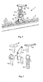
- each of the beams 5 comprises groups of four screw holes 23 arranged along the beams, which can be seen in Fig. 2 , which shows one of the fixture devices 7 as mounted at one of the beams 5.
- a group of four screw holes 23 receives four screws 22 of the fixture device 7 while the fixture device 7 is mounted at the beam 5.
- the groups of four screw holes 23 are preferably arranged with a desirable pitch in the longitudinal direction of the beams.
- the fixture devices 7 are mountable along the beams 5 at a finite number of selectable fixed positions.
- each group of four screw holes 23 may be arranged in the corners of an imaginary square so that each fixture device 7 can be releasably attachable to the beams 5 in four fixed rotational positions, which are mutually separated by 90 degrees.
- Each fixture device 7 comprises according to one aspect of the invention a column 21, an adapter 24, and a head 27 as being illustrated in Fig. 2 .
- Each column 21 comprises screws 22 and is releasably mountable to the beams 5.
- each column comprises a bore, in which each adapter 24 can be inserted, and a locking mechanism 25 in order to lock the respective adapter 24 in a desired position.
- the bore of each column can be symmetrically or asymmetrically located with respect to the rotation of the column in the horizontal plane.
- Each adapter 24 comprises a number of teeth, grooves, slots or similar in its lower portion, which are inserted in a respective column 21 during mounting.
- the adapters can be inserted in the column in only one fixed rotational position.
- the adapter 24 can be stepwise moved upwards and downwards in the column 21 and be fastened at a desired position.
- the adapters 24 are releasably mountable at the columns 21 at a finite number of selectable vertical positions in order to obtain mounted fixture devices of a finite number of selectable fixed heights.
- each adapter 24 comprises a recess, into which each head 27 can be inserted, and a locking mechanism 28 in order to lock respective head 27 in a desired position.
- FIG. 3 an adapter 24 and a number of different heads 27 are shown.
- the heads have a lower portion 31, which fits into the recess of each adapter in two different rotational positions, which are turned 180 degrees in relation to one another in the horizontal plane.
- the heads 27 can thus be releasably mountable at the adapters 24 in a finite number of selectable fixed orientations.
- the parts of the fixture devices column, adapter and head can have different appearances, engagement and locking mechanism than the above shown as long as they comprise these three parts which are releasably attachable to one another and where at least one part can be mounted in several different positions in order to adjust the height of the mounted fixture devices.
- Figs. 4a-b show an example of an alternative embodiment of an adapter 24'.
- a head is fastened between two clamping washers 42 on each side of respective position, which clamping washers 42 are mounted at the adapter 24' by means of screws 43.
- a head is fastened by screws in screw holes 44 intended therefore.
- a version of this adapter has a further clamping washer in the third position 41c, which clamping washer is fastened to the adapter by a screw.
- four identical positions are created, at which heads can be mounted, where the positions are separated by 90 degrees from one another.
- the columns 21 and the adapters 24 are preferably universal and can be used for all vehicles, which are to be repaired or inspected.
- the columns 21 can be provided in different heights.
- a levelling bench may need 20-25 columns in for instance six different heights.
- the adapters 24 can also be provided in different heights or lengths, for instance a levelling bench may require about 20 adapters in three different heights. This set of columns 21 and adapters 24 can be used for a large number of vehicle models.
- the adapters can be provided in two versions, for instance in the version shown in Fig. 4 and in the version described above.
- the heads 27 are tailored for a particular vehicle model so that when they are mounted they define certain specific reference points of the vehicle, which is to be repaired or inspected. Certainly similar heads 27 may be used for more than one model but typically the heads 27 are manufactured and marketed in a set, which is intended for a particular vehicle model. A set may consist of for instance about 20-30 heads. For such a set a data sheet is provided, which shows the columns and adapters, which shall be used with the heads, as well as where and how the columns, adapters, and heads shall be mounted for the vehicle model in question.
- a repair shop has not a complete set of heads for all the vehicle models occurring on the market - it will be far to expensive.
- a shop has a few number of sets for the most common models or possibly no sets at all. They are instead ordered when required. Typically, they are rented during a limited time, during which the repair of the vehicle is performed. Thus, transportation of heads occurs to a considerable extent.
- An advantage of the heads according to a preferred embodiment of the present invention is that they are small and of light weight.
- a set of heads is neither bulky nor particularly heavy and can be transported simply and to a low cost - unlike the heads which are used according to the known art.
- the heads which are disclosed in for instance US 4,781,045 , correspond to both the heads and the adapters according to the present invention and have thus also the function of adjusting the height of the fixture devices. Hereby they will be much more bulky and heavy.
- the heads according to the invention are also simpler and cheaper to manufacture.
- a set of adapters are used for all car models which are to be repaired or inspected and these have thus not to be ordered for each new car model which is to be handled.
- a further advantage of the fixture device divided into three pieces according to a preferred embodiment of the invention is that the columns and the adapters can be combined in more than one manner in order to reach a desired height of the fixture device.
- a column of medium height and an adapter of medium height reach a certain height, but the same height can be reached by a lower column and a higher adapter or by a higher column and a lower adapter.
- a larger flexibility is reached and a less number of columns would be required for a certain number of vehicle models than what would be required by the solution according to the known art.
- the levelling bench arrangement of the present invention can alternatively be arranged for variable or continuous adjustment.
- the beams can be lockable to the elongated support structure 3 at continuously adjustable positions
- the fixture devices 7 can be mountable at the beams at continuously adjustable positions
- the adapters 24 can be releasably mountable at the columns 21 in order to obtain mounted fixture devices of continuously adjustable heights
- the heads 27 can be releasably mountable at the adapters 24 in continuously adjustable rotations. In such instances different scales on the different parts would facilitate mounting and adjustment of the levelling bench arrangement.
- FIG. 5-7 show in perspective views the levelling bench arrangement of Fig. 1 at different stages of a method for alignment of columns, adapters, and heads in relation to a vehicle, this aspect of the present invention will be further described.
- the method starts from an empty frame or levelling bench 1 which is shown in Fig. 5 .
- the levelling bench 1 can be mounted on a scissor lift or other lifting device.
- a vehicle which is to be repaired on inspected, is arranged (for instance by means of the lifting device and a number of holding devices) at a height above the levelling bench 1 which makes simple access possible for mounting of the levelling bench arrangement, after which the elongated support structure 3 is loosely arranged on the levelling bench 1.
- the elongated support structure 3 is arranged in a direction essentially parallel (y-direction) with a longitudinal direction (y-direction) of the vehicle.
- the number of beams 5 has to be at least two and can at maximum be equal to the number, which is to be used. Preferably two to three or two to four beams are used. The result is shown in Fig. 6 .
- Next fixture devices 7 are releasably mounted at the beams 5.
- the number of fixture devices 7, which are used for the alignment shall preferably be at least two. Typically, four to six fixture devices are used. The result is shown in Fig. 7 .
- the beams 5 shall be locked to the elongated support structure 3 and the fixture devices 7 should be mounted at the beams 5 at positions, which correspond to the model of the vehicle in question.
- the vehicle is then lowered to the position it shall have during the repair or the inspection and the fixture devices 7 are aligned with respect to the vehicle by means of continuously moving the beams 5 and the elongated support structure 3 as a single unit in the horizontal plane and at least two of the beams 5 are releasably attached to the levelling bench 1, thereby locking the beams 5 and the elongated support structure 3 to the levelling bench 1. In the illustrated case there are only two beams and these are then attached to the levelling bench 1. Alternatively, instead of lowering the vehicle the levelling bench can be raised by means of the lifting device.
- the vertical movement of the vehicle relative to the levelling bench arrangement and the horizontal movement (alignment) of the beams 5 and the elongated support structure 3 as a single unit can be performed in stages with a finer and finer adjustment of the beams 5 and the elongated support structure 3 the closer the vehicle is relative to the levelling bench arrangement in the vertical direction.
- the beams 5 and the elongated support structure 3 are resting on the levelling bench 1 and they are moved as a single unit by means of pushing and/or drawing the single unit over the levelling bench 1 by a force which exceeds the friction force between the levelling bench 1/the beams 5 and the elongated support structure 3.
- the vehicle may rest with part of its weight on at least some of the fixture devices 7. Possibly, also other none shown holding devices or fastening devices may be provided.
- the above described alignment method can be used for other fixture devices than those being described with reference to Figs. 2-4 .
- the method can be used for fixture devices in two pieces, each comprising a column releasably mountable to a support and a head releasably mountable to the column, which is described in the above-mentioned US 4,781,045 .
- the method can also be used with fixture devices, each of which being made in one piece in accordance with older art.
- the elongated support structure 3 and the beams 5 can be exchanged for a thicker support structure, frame structure or structure, wherein the fixture devices are mounted directly to this structure.
- a thicker support structure, frame structure or structure wherein the fixture devices are mounted directly to this structure.
- Such structure can be in one piece or be assembled. If the above described alignment method is applied, it is this thicker support structure, frame structure or structure, which with at least few fixture devices mounted thereon is moved in the horizontal plane above the levelling bench 1 during the alignment.
Landscapes
- Engineering & Computer Science (AREA)
- Mechanical Engineering (AREA)
- Physics & Mathematics (AREA)
- General Physics & Mathematics (AREA)
- Radar, Positioning & Navigation (AREA)
- Remote Sensing (AREA)
- Vehicle Cleaning, Maintenance, Repair, Refitting, And Outriggers (AREA)
- Body Structure For Vehicles (AREA)
- Preparation Of Compounds By Using Micro-Organisms (AREA)
- Fittings On The Vehicle Exterior For Carrying Loads, And Devices For Holding Or Mounting Articles (AREA)
- Workshop Equipment, Work Benches, Supports, Or Storage Means (AREA)
- Load-Engaging Elements For Cranes (AREA)
Claims (22)
- Verfahren zur Ausrichtung eines Fahrzeugs und eine Ausgleichsbankanordnung in Bezug aufeinander, wobei die Ausgleichsbankanordnung eine Ausgleichsbank (1), eine Unterstützungsanordnung (3, 5) und eine Vielzahl von Befestigungsvorrichtungen (7) umfasst, wobei das Verfahren die folgenden Schritte umfasst:- Anordnung der Unterstützungsanordnung (3, 5) auf der Ausgleichsbank,- lösbare Befestigung der Befestigungsvorrichtungen (7) an der Unterstützungsanordnung,- Anordnung eines Fahrzeugs, welches repariert oder untersucht werden soll in einer ersten Position über der Ausgleichsbank,- Ausrichtung der Befestigungsvorrichtungen (7) in Bezug auf das Fahrzeug mittels kontinuierlichem Bewegen der Unterstützungsanordnungen (3, 5) in einer horizontalen Ebene, so dass die Befestigungsvorrichtungen bestimmte, spezifische Referenzpunkte des Fahrzeugs definieren, und- lösbare Befestigung der Unterstützungsanordnung (3, 5) an der Ausgleichsbank, wobei die Unterstützungsanordnung mit der Ausgleichsbank in der ausgerichteten Position verriegelt wird, dadurch gekennzeichnet, dass- die Unterstützungsanordnung (3, 5) gestreckt ist, und mit der Ausgleichsbank (1) verriegelt ist, so dass die gestreckte Unterstützungsanordnung in einer Richtung orientiert ist, die im Wesentlichen parallel (y) mit einer längsgerichteten Richtung (y) des Fahrzeugs ist.
- Verfahren nach Anspruch 1, wobei:- die Unterstützungsanordnung (3, 5) eine gestreckte Unterstützungsstruktur (3) und eine Vielzahl von Trägem (5) einschließt,- die Anordnung der Unterstützungsanordnung (3, 5) auf der Ausgleichsbank ein Anordnen der Unterstützungsstruktur auf der Ausgleichsbank und ein Verriegeln der Träger mit der Unterstützungsstruktur zumindest in einer horizontalen Ebene einschließt,- die lösbare Befestigung der Befestigungsvorrichtungen (7) an der Unterstützungsanordnung ein lösbares Befestigen der Befestigungsvorrichtungen an den Trägem einschließt, und- die Ausrichtung der Befestigungsvorrichtungen (7) in Bezug auf das Fahrzeug ein kontinuierliches Bewegen der Träger und der Unterstützungsstruktur als eine einzige Einheit in der horizontalen Ebene einschließt, so dass die Befestigungsvorrichtungen bestimmte spezifische Referenzpunke des Fahrzeugs definieren.
- Verfahren nach Anspruch 2, wobei- das zu reparierende oder zu untersuchende Fahrzeug in einer zweiten Position über der Ausgleichsbank (1) angeordnet ist, bevor die Befestigungsvorrichtungen an den Trägern befestigt sind, wobei die zweite Position höher als die erste Position ist, und- das Fahrzeug in der ersten Position durch Absenken des Fahrzeugs angeordnet ist.
- Verfahren nach Anspruch 2 oder 3, wobei die Ausgleichsbankanordnung weitere Träger (5) umfasst, wobei die weiteren Träger mit der Unterstützungsstruktur (3) zumindest in der horizontalen Ebene verriegelt sind, nachdem zumindest einer der Träger oder die Unterstützungsstruktur an der Ausgleichsbank befestigt wurden.
- Verfahren nach Anspruch 2 oder 3, wobei die Ausgleichsbankanordnung weitere Befestigungsvorrichtungen (7) umfasst, wobei die weiteren Befestigungsvorrichtungen an weiteren Trägem befestigt sind.
- Verfahren nach Anspruch 5, wobei die Träger an der gestreckten Unterstützungsstruktur senkrecht (x) zu der Ausdehnung (y) davon verriegelt sind.
- Verfahren nach irgendeinem der Ansprüche 2 bis 6, wobei die Träger (5) an der Unterstützungsstruktur (3) an ausgewählten Positionen einer endlichen Anzahl von auswählbaren Positionen entlang der Ausdehnung der Unterstützungsstruktur verriegelt sind.
- Verfahren nach irgendeinem der Ansprüche 2 bis 7, wobei die Befestigungsvorrichtungen (7) an den Trägern an ausgewählten Positionen einer endlichen Anzahl von auswählbaren Positionen (23) entlang der Ausdehnung der Träger befestigt sind.
- Verfahren nach irgendeinem der Ansprüche 2 bis 8, wobei jede der Befestigungsvorrichtungen (7) eine Säule umfasst, die lösbar an den Trägern befestigbar ist, und einen Kopf umfasst, der lösbar an der Säule befestigbar ist, wobei der Schritt des Befestigens der Befestigungsvorrichtungen an den Trägern die Schritte des Befestigens der Säule an den Trägern und des Befestigens der Köpfe an den Säulen umfasst.
- Verfahren nach Anspruch 9, wobei die Köpfe an den Säulen in einer ausgewählten vertikalen Position aus einer endlichen Anzahl von auswählbaren vertikalen Positionen befestigt sind, um befestigte Befestigungsvorrichtungen einer ausgewählten Höhe aus einer endlichen Anzahl von auswählbaren Höhen zu erhalten.
- Verfahren nach irgendeinem der Ansprüche 2 bis 8, wobei jede der Befestigungsvorrichtungen eine Säule (21) umfasst, die lösbar an den Trägern befestigbar ist, einen Adapter (24), der lösbar an der Säule befestigbar ist, und einen Kopf (27), der lösbar an einem Adapter befestigbar ist, wobei der Schritt des Befestigens der Befestigungsvorrichtungen an den Trägern die Schritte des Befestigens der Säulen an den Trägem, des Befestigens der Adapter an den Säulen, und des Befestigens der Köpfe an den Adaptern umfasst.
- Verfahren nach Anspruch 11, wobei die Adapter (24) an den Säulen (21) in einer ausgewählten vertikalen Position aus einer endlichen Anzahl von auswählbaren vertikalen Positionen befestigt sind, um befestigte Befestigungsvorrichtungen einer ausgewählten Höhe aus einer endlichen Anzahl von auswählbaren Höhen zu erhalten.
- Verfahren nach Anspruch 11 oder 12, wobei die Köpfe (27) an den Adaptern (24) in ausgewählten Orientierungen aus einer endlichen Anzahl von auswählbaren Orientierungen befestigt sind.
- Ausgleichsbankanordnung, umfassend eine Ausgleichsbank (1), eine Unterstützungsanordnung (3, 5) und eine Vielzahl von Befestigungsvorrichtungen (7), wobei- die Vielzahl von Befestigungsvorrichtungen (7) lösbar an der Unterstützungsanordnung befestigbar sind,- die Unterstützungsanordnung kontinuierlich in einer horizontalen Ebene auf der Ausgleichsbank mit den Befestigungsvorrichtungen (7) beweglich ist, die auf der Unterstützungsanordnung (3, 5) befestigt sind, und dabei eine Ausrichtung der Befestigungsvorrichtungen in Bezug auf ein Fahrzeug erreichen, welches repariert oder untersucht werden soll, und welches daher über der Ausgleichsbank angeordnet ist, möglicherweise, wobei die Befestigungsvorrichtungen bestimmte, spezifische Referenzpunkte des Fahrzeugs in einer ausgerichteten Position definieren, und- die Unterstützungsanordnung (3, 5) lösbar an der Ausgleichsbank befestigbar ist, und dabei ein Verriegeln der Unterstützungsanordnung an der Ausgleichsbank in einer ausgerichteten Position in Bezug auf das Fahrzeug ermöglicht, dadurch gekennzeichnet, dass- die Unterstützungsanordnung (3, 5) gestreckt ist, und in einer Richtung (y) im Wesentlichen parallel zu einer längsgerichteten Richtung (y) des Fahrzeugs orientiert ist, wenn sie an der Ausgleichsbank (1) verriegelt ist.
- Ausgleichsbankanordnung nach Anspruch 14, wobei- die Unterstützungsanordnung (3, 5) eine gestreckte Unterstützungsstruktur (3) und eine Vielzahl von Trägem (5) einschließt,- die Träger (5) an der gestreckten Unterstützungsstruktur zumindest in einer horizontalen Ebene verriegelbar sind,- die Unterstützungsanordnung (3, 5) kontinuierlich in einer horizontalen Ebene auf der Ausgleichsbank beweglich ist, mittels der Träger und der Unterstützungsstruktur, die als einstückige Einheit kontinuierlich in der horizontalen Ebene auf der Ausgleichsbank beweglich sind, und- die Unterstützungsanordnung (3, 5) lösbar an der Ausgleichsbank befestigbar ist, mittels zumindest der gestreckten Unterstützungsstruktur oder einigen der Trägem, die lösbar an der Ausgleichsbank befestigbar sind.
- Ausgleichsbankanordnung nach Anspruch 15, wobei die Träger (5) an der gestreckten Unterstützungsstruktur (3) senkrecht (x) zu der Ausdehnung (y) davon verriegelbar sind.
- Ausgleichsbankanordnung nach Anspruch 15 oder 16, wobei die Träger (5) an der gestreckten Unterstützungsstruktur (3) an einer endlichen Anzahl von auswählbaren Positionen entlang der Ausdehnung der gestreckten Unterstützungsstruktur verriegelbar sind.
- Ausgleichsbankanordnung nach irgendeinem der Ansprüche 15 bis 17, wobei die Befestigungsvorrichtungen (7) lösbar an den Trägem (5) in ausgewählten Positionen aus einer endlichen Anzahl von auswählbaren Positionen (23) entlang der Ausdehnung der Träger befestigbar sind.
- Ausgleichsbankanordnung nach irgendeinem der Ansprüche 15 bis 18, wobei jede der Befestigungsvorrichtungen (7) eine Säule umfassen, die lösbar an den Trägem befestigbar ist, und einen Kopf, der lösbar an der Säule befestigbar ist.
- Ausgleichsbankanordnung nach irgendeinem der Ansprüche 15 bis 19, wobei jede der Befestigungsvorrichtungen (7) eine Säule (21) umfasst, die lösbar an den Trägem befestigbar ist, einen Adapter (24), der lösbar an der Säule befestigbar ist, und einen Kopf (27), der lösbar an dem Adapter befestigbar ist.
- Ausgleichsbankanordnung nach Anspruch 20, wobei die Adapter (24) lösbar an den Säulen (21) in einer endlichen Anzahl von auswählbaren vertikalen Positionen befestigbar sind, um befestigte Befestigungsvorrichtungen in einer endlichen Anzahl von auswählbaren Höhen zu erhalten.
- Ausgleichsbankanordnung nach Anspruch 20 oder 21, wobei die Köpfe (27) lösbar an den Adaptern (24) in einer endlichen Anzahl von auswählbaren Orientierungen befestigbar sind.
Applications Claiming Priority (1)
| Application Number | Priority Date | Filing Date | Title |
|---|---|---|---|
| SE0601847A SE0601847L (sv) | 2006-09-07 | 2006-09-07 | Förfarande för riktning av ett fordon samt riktbänksarrangemang |
Publications (2)
| Publication Number | Publication Date |
|---|---|
| EP1897630A1 EP1897630A1 (de) | 2008-03-12 |
| EP1897630B1 true EP1897630B1 (de) | 2009-05-06 |
Family
ID=38007657
Family Applications (1)
| Application Number | Title | Priority Date | Filing Date |
|---|---|---|---|
| EP07445032A Active EP1897630B1 (de) | 2006-09-07 | 2007-08-31 | Verfahren zur Ausrichtung eines Fahrzeugs und Ausgleichsbankanordnung |
Country Status (7)
| Country | Link |
|---|---|
| US (2) | US9090230B2 (de) |
| EP (1) | EP1897630B1 (de) |
| JP (1) | JP2008120595A (de) |
| CN (1) | CN101138773B (de) |
| AT (1) | ATE430635T1 (de) |
| DE (1) | DE602007001058D1 (de) |
| SE (1) | SE0601847L (de) |
Families Citing this family (12)
| Publication number | Priority date | Publication date | Assignee | Title |
|---|---|---|---|---|
| SE530320C2 (sv) * | 2006-09-07 | 2008-04-29 | Car O Liner Ab | Riktbänksarrangemang, tillbehörssats för ett riktbänksarrangemang, samt förfarande för iordningställande av en riktbänk för en särskild fordonsmodell |
| US8839507B2 (en) * | 2009-12-15 | 2014-09-23 | Comau, Inc. | Remote locking apparatus for securing a vehicle body to a vehicle body support |
| DE102010040655A1 (de) * | 2010-09-13 | 2012-03-15 | Robert Bosch Gmbh | Verfahren und Vorrichtung zum Kalibrieren eines Referenzsystems zur Fahrzeugvermessung |
| CN102672006A (zh) * | 2012-04-25 | 2012-09-19 | 上海晓奥享荣汽车工业装备有限公司 | 汽车车架本体矫正装置 |
| CN103521555B (zh) * | 2012-07-02 | 2015-07-08 | 北汽福田汽车股份有限公司 | 卡车车架校正设备和卡车车架在竖直方向尺寸的校正方法 |
| CN104029660A (zh) * | 2014-06-05 | 2014-09-10 | 江苏中一汽车机械设备制造有限公司 | 重载汽车校正架 |
| CN105855866B (zh) * | 2015-01-22 | 2020-03-27 | 标致·雪铁龙汽车公司 | 一种用于车辆的部件模型的定位调整设备 |
| CN105537322B (zh) * | 2015-12-08 | 2017-07-21 | 臧汝涛 | 一种快捷式汽车钣金工作台 |
| EP3473975A1 (de) * | 2017-10-19 | 2019-04-24 | Renishaw PLC | Befestigungsvorrichtung |
| CN109501760B (zh) * | 2018-04-10 | 2022-06-03 | 蔚来控股有限公司 | 浮动装置、换电设备和换电站 |
| CN110001600B (zh) * | 2018-12-07 | 2023-08-01 | 蔚来控股有限公司 | 快速换电系统和快速换电方法 |
| CN109941238B (zh) * | 2018-12-07 | 2023-04-18 | 蔚来控股有限公司 | 车辆承载组件、承载装置、换电平台和车辆换电操作方法 |
Family Cites Families (24)
| Publication number | Priority date | Publication date | Assignee | Title |
|---|---|---|---|---|
| US4055061A (en) * | 1976-04-26 | 1977-10-25 | Applied Power, Inc. | Apparatus for reforming and straightening vehicles |
| FR2423748A1 (fr) * | 1978-04-21 | 1979-11-16 | Celette Sa | Appareillage pour le controle des deformations d'une carrosserie de vehicule |
| SE415293B (sv) * | 1978-11-14 | 1980-09-22 | Bygg Och Transportekonomie Ab | Forfarande och anordning for dimensionskontroll av fordon |
| IT1135812B (it) * | 1981-05-15 | 1986-08-27 | Marchio Achille | Banco per la riparazione di scocche di autoveicoli |
| IT1107051B (it) | 1983-02-28 | 1985-11-18 | Car Bench Spa | Banco per la riparazione di scoddhe di autoveicoli provvisto di supporti unificati per dime dotati di tre gradi di liberta' di movimento |
| FR2544070B3 (fr) * | 1983-04-06 | 1985-12-27 | Celette Sa | Appareillage pour le montage d'une carrosserie de voiture sur un marbre de controle |
| JPS61105402A (ja) * | 1984-10-29 | 1986-05-23 | Shugo Fuwa | 自動車鈑金修理用測定機 |
| FR2590014A1 (fr) | 1985-09-19 | 1987-05-15 | Sefac | Dispositif d'assemblage interchangeable et adaptable, d'elements des bancs de montage, de controle et de reparation des carrosseries de vehicules automobiles notamment |
| SE452366B (sv) * | 1986-03-18 | 1987-11-23 | Samefa Ab | Lengdmetningsdon |
| US4781045A (en) * | 1986-04-01 | 1988-11-01 | Celette S.A. | Vehicle checking and straightening equipment with interchangeable operating heads |
| US4761984A (en) | 1986-09-26 | 1988-08-09 | Fuscaldo Jr Frank | Apparatus for supporting a vehicle for straightening and alignment |
| JPS63165704A (ja) * | 1986-12-26 | 1988-07-09 | Shugo Fuwa | 自動車の鈑金修理における測定基準点の測定方法 |
| JPS63247637A (ja) * | 1987-04-02 | 1988-10-14 | Shugo Fuwa | 自動車鈑金修理用測定機 |
| FR2621261B1 (fr) * | 1987-10-06 | 1994-05-20 | Sefac | Marbre pour le montage, le controle et la reparation de carrosseries de vehicules automobiles notamment |
| US4899457A (en) * | 1988-11-10 | 1990-02-13 | Hein-Werner Corporation | Vehicle frame measuring bridge including spring actuated telescoping legs |
| JPH0749260B2 (ja) * | 1989-02-09 | 1995-05-31 | 周吾 不破 | 車輌修正用架台 |
| FR2652050A1 (fr) * | 1989-09-19 | 1991-03-22 | Celette Sa | Dispositif de fixation d'un vehicule et de reglage de sa position sur un chassis en vue de sa reparation. |
| IT1244046B (it) * | 1990-07-17 | 1994-07-01 | Franco Mingardi | Perfezionamenti ai banchi-ponte per la riparazione delle scocche e telai danneggiati di autoveicoli. |
| JPH04230453A (ja) * | 1990-12-20 | 1992-08-19 | Velazquez Nito Antonio | 車体測定システム |
| JP3068657B2 (ja) * | 1991-03-13 | 2000-07-24 | 日本パワーエンジニアリング株式会社 | 車体計測装置 |
| JPH06179353A (ja) * | 1992-04-23 | 1994-06-28 | Nippon Power Eng Kk | プリングタワー取付け機構 |
| CN2129184Y (zh) | 1992-08-14 | 1993-04-07 | 吴亚新 | 汽车校正平台 |
| US5357777A (en) * | 1993-05-28 | 1994-10-25 | Sam Castellano | Positioning apparatus for a frame rack for inspection and alignment of automotive vehicle unibodies and frames |
| JPH07315181A (ja) * | 1994-05-25 | 1995-12-05 | Ryuzo Yamashita | 車枠測定矯正装置の測定装置、スライド装置、台式作業台、固定y軸具、車枠保持馬移動具、矯正タワー及びタワー案内装置 |
-
2006
- 2006-09-07 SE SE0601847A patent/SE0601847L/sv unknown
-
2007
- 2007-08-31 DE DE602007001058T patent/DE602007001058D1/de active Active
- 2007-08-31 AT AT07445032T patent/ATE430635T1/de not_active IP Right Cessation
- 2007-08-31 EP EP07445032A patent/EP1897630B1/de active Active
- 2007-09-06 JP JP2007231586A patent/JP2008120595A/ja active Pending
- 2007-09-06 US US11/900,001 patent/US9090230B2/en active Active
- 2007-09-07 CN CN2007101492535A patent/CN101138773B/zh active Active
-
2014
- 2014-05-05 US US14/270,184 patent/US20140360032A1/en not_active Abandoned
Also Published As
| Publication number | Publication date |
|---|---|
| CN101138773B (zh) | 2012-05-02 |
| US20140360032A1 (en) | 2014-12-11 |
| SE529126C2 (sv) | 2007-05-08 |
| US9090230B2 (en) | 2015-07-28 |
| US20080087201A1 (en) | 2008-04-17 |
| EP1897630A1 (de) | 2008-03-12 |
| SE0601847L (sv) | 2007-05-08 |
| ATE430635T1 (de) | 2009-05-15 |
| CN101138773A (zh) | 2008-03-12 |
| JP2008120595A (ja) | 2008-05-29 |
| DE602007001058D1 (de) | 2009-06-18 |
Similar Documents
| Publication | Publication Date | Title |
|---|---|---|
| EP1897630B1 (de) | Verfahren zur Ausrichtung eines Fahrzeugs und Ausgleichsbankanordnung | |
| CN112272597B (zh) | 用于组装力矩连接部件的方法和设备 | |
| US6367788B1 (en) | Workpiece support apparatus | |
| US4519236A (en) | Clamping device to be mounted on a frame or bench jig for checking any deformations of a vehicle body | |
| US7810245B2 (en) | Levelling bench arrangement, set of accessories for a levelling bench arrangement, and method for preparation of a levelling bench for a particular vehicle model | |
| US4761984A (en) | Apparatus for supporting a vehicle for straightening and alignment | |
| US4603570A (en) | Universal dedicated fixture for frame straightening rack | |
| US6216524B1 (en) | Dual clamping adapter and vehicle repairing device | |
| US5544861A (en) | Adjustable riser-ramp assembly | |
| CN218051253U (zh) | 一种用于尾气后处理总成装配的工装 | |
| CN220127994U (zh) | 一种车架纵梁组装专用工装台 | |
| US6182493B1 (en) | Dual clamping adapter and vehicle repairing device | |
| EP0085253A1 (de) | Messgeräte für die Ausrichtung einer Fahrzeugkarosserie | |
| CN218837691U (zh) | 一种用于钢结构加工的翻转装置 | |
| US6568237B1 (en) | Apparatus and method for vehicle manipulative anchoring | |
| CN1500017A (zh) | 车体框架修正机 | |
| US20190211712A1 (en) | Device for assembling and disassembling a component of a gas turbine | |
| CN220753730U (zh) | 一种天线可调节安装支架 | |
| US20040172170A1 (en) | Portable wheel alignment device | |
| EP1479481B1 (de) | Tragbare werkbank | |
| JP2004051033A (ja) | 車体フレーム保持装置 | |
| CN119754174A (zh) | 超宽钢箱系杆拱肋节段拼装安全快速固定装置及方法 | |
| CA1183344A (en) | Vehicle frame measuring system | |
| JP2704375B2 (ja) | 車両修正用の固定補助具 | |
| CN110640376A (zh) | 一种风机叶片焊接辅助设备 |
Legal Events
| Date | Code | Title | Description |
|---|---|---|---|
| PUAI | Public reference made under article 153(3) epc to a published international application that has entered the european phase |
Free format text: ORIGINAL CODE: 0009012 |
|
| AK | Designated contracting states |
Kind code of ref document: A1 Designated state(s): AT BE BG CH CY CZ DE DK EE ES FI FR GB GR HU IE IS IT LI LT LU LV MC MT NL PL PT RO SE SI SK TR |
|
| AX | Request for extension of the european patent |
Extension state: AL BA HR MK YU |
|
| 17P | Request for examination filed |
Effective date: 20080213 |
|
| 17Q | First examination report despatched |
Effective date: 20080318 |
|
| AKX | Designation fees paid |
Designated state(s): AT BE BG CH CY CZ DE DK EE ES FI FR GB GR HU IE IS IT LI LT LU LV MC MT NL PL PT RO SE SI SK TR |
|
| GRAP | Despatch of communication of intention to grant a patent |
Free format text: ORIGINAL CODE: EPIDOSNIGR1 |
|
| GRAS | Grant fee paid |
Free format text: ORIGINAL CODE: EPIDOSNIGR3 |
|
| GRAA | (expected) grant |
Free format text: ORIGINAL CODE: 0009210 |
|
| AK | Designated contracting states |
Kind code of ref document: B1 Designated state(s): AT BE BG CH CY CZ DE DK EE ES FI FR GB GR HU IE IS IT LI LT LU LV MC MT NL PL PT RO SE SI SK TR |
|
| REG | Reference to a national code |
Ref country code: GB Ref legal event code: FG4D |
|
| REG | Reference to a national code |
Ref country code: CH Ref legal event code: EP |
|
| REG | Reference to a national code |
Ref country code: IE Ref legal event code: FG4D |
|
| REF | Corresponds to: |
Ref document number: 602007001058 Country of ref document: DE Date of ref document: 20090618 Kind code of ref document: P |
|
| PG25 | Lapsed in a contracting state [announced via postgrant information from national office to epo] |
Ref country code: LT Free format text: LAPSE BECAUSE OF FAILURE TO SUBMIT A TRANSLATION OF THE DESCRIPTION OR TO PAY THE FEE WITHIN THE PRESCRIBED TIME-LIMIT Effective date: 20090506 Ref country code: ES Free format text: LAPSE BECAUSE OF FAILURE TO SUBMIT A TRANSLATION OF THE DESCRIPTION OR TO PAY THE FEE WITHIN THE PRESCRIBED TIME-LIMIT Effective date: 20090817 Ref country code: PT Free format text: LAPSE BECAUSE OF FAILURE TO SUBMIT A TRANSLATION OF THE DESCRIPTION OR TO PAY THE FEE WITHIN THE PRESCRIBED TIME-LIMIT Effective date: 20090906 Ref country code: AT Free format text: LAPSE BECAUSE OF FAILURE TO SUBMIT A TRANSLATION OF THE DESCRIPTION OR TO PAY THE FEE WITHIN THE PRESCRIBED TIME-LIMIT Effective date: 20090506 Ref country code: FI Free format text: LAPSE BECAUSE OF FAILURE TO SUBMIT A TRANSLATION OF THE DESCRIPTION OR TO PAY THE FEE WITHIN THE PRESCRIBED TIME-LIMIT Effective date: 20090506 |
|
| NLV1 | Nl: lapsed or annulled due to failure to fulfill the requirements of art. 29p and 29m of the patents act | ||
| PG25 | Lapsed in a contracting state [announced via postgrant information from national office to epo] |
Ref country code: SI Free format text: LAPSE BECAUSE OF FAILURE TO SUBMIT A TRANSLATION OF THE DESCRIPTION OR TO PAY THE FEE WITHIN THE PRESCRIBED TIME-LIMIT Effective date: 20090506 Ref country code: SE Free format text: LAPSE BECAUSE OF FAILURE TO SUBMIT A TRANSLATION OF THE DESCRIPTION OR TO PAY THE FEE WITHIN THE PRESCRIBED TIME-LIMIT Effective date: 20090806 Ref country code: PL Free format text: LAPSE BECAUSE OF FAILURE TO SUBMIT A TRANSLATION OF THE DESCRIPTION OR TO PAY THE FEE WITHIN THE PRESCRIBED TIME-LIMIT Effective date: 20090506 Ref country code: NL Free format text: LAPSE BECAUSE OF FAILURE TO SUBMIT A TRANSLATION OF THE DESCRIPTION OR TO PAY THE FEE WITHIN THE PRESCRIBED TIME-LIMIT Effective date: 20090506 Ref country code: LV Free format text: LAPSE BECAUSE OF FAILURE TO SUBMIT A TRANSLATION OF THE DESCRIPTION OR TO PAY THE FEE WITHIN THE PRESCRIBED TIME-LIMIT Effective date: 20090506 Ref country code: IS Free format text: LAPSE BECAUSE OF FAILURE TO SUBMIT A TRANSLATION OF THE DESCRIPTION OR TO PAY THE FEE WITHIN THE PRESCRIBED TIME-LIMIT Effective date: 20090906 |
|
| PG25 | Lapsed in a contracting state [announced via postgrant information from national office to epo] |
Ref country code: EE Free format text: LAPSE BECAUSE OF FAILURE TO SUBMIT A TRANSLATION OF THE DESCRIPTION OR TO PAY THE FEE WITHIN THE PRESCRIBED TIME-LIMIT Effective date: 20090506 Ref country code: DK Free format text: LAPSE BECAUSE OF FAILURE TO SUBMIT A TRANSLATION OF THE DESCRIPTION OR TO PAY THE FEE WITHIN THE PRESCRIBED TIME-LIMIT Effective date: 20090506 Ref country code: RO Free format text: LAPSE BECAUSE OF FAILURE TO SUBMIT A TRANSLATION OF THE DESCRIPTION OR TO PAY THE FEE WITHIN THE PRESCRIBED TIME-LIMIT Effective date: 20090506 Ref country code: CZ Free format text: LAPSE BECAUSE OF FAILURE TO SUBMIT A TRANSLATION OF THE DESCRIPTION OR TO PAY THE FEE WITHIN THE PRESCRIBED TIME-LIMIT Effective date: 20090506 |
|
| PG25 | Lapsed in a contracting state [announced via postgrant information from national office to epo] |
Ref country code: BE Free format text: LAPSE BECAUSE OF FAILURE TO SUBMIT A TRANSLATION OF THE DESCRIPTION OR TO PAY THE FEE WITHIN THE PRESCRIBED TIME-LIMIT Effective date: 20090506 Ref country code: SK Free format text: LAPSE BECAUSE OF FAILURE TO SUBMIT A TRANSLATION OF THE DESCRIPTION OR TO PAY THE FEE WITHIN THE PRESCRIBED TIME-LIMIT Effective date: 20090506 |
|
| PLBE | No opposition filed within time limit |
Free format text: ORIGINAL CODE: 0009261 |
|
| STAA | Information on the status of an ep patent application or granted ep patent |
Free format text: STATUS: NO OPPOSITION FILED WITHIN TIME LIMIT |
|
| PG25 | Lapsed in a contracting state [announced via postgrant information from national office to epo] |
Ref country code: MC Free format text: LAPSE BECAUSE OF NON-PAYMENT OF DUE FEES Effective date: 20090831 Ref country code: BG Free format text: LAPSE BECAUSE OF FAILURE TO SUBMIT A TRANSLATION OF THE DESCRIPTION OR TO PAY THE FEE WITHIN THE PRESCRIBED TIME-LIMIT Effective date: 20090806 |
|
| 26N | No opposition filed |
Effective date: 20100209 |
|
| REG | Reference to a national code |
Ref country code: IE Ref legal event code: MM4A |
|
| PG25 | Lapsed in a contracting state [announced via postgrant information from national office to epo] |
Ref country code: IE Free format text: LAPSE BECAUSE OF NON-PAYMENT OF DUE FEES Effective date: 20090831 |
|
| PG25 | Lapsed in a contracting state [announced via postgrant information from national office to epo] |
Ref country code: GR Free format text: LAPSE BECAUSE OF FAILURE TO SUBMIT A TRANSLATION OF THE DESCRIPTION OR TO PAY THE FEE WITHIN THE PRESCRIBED TIME-LIMIT Effective date: 20090807 |
|
| PG25 | Lapsed in a contracting state [announced via postgrant information from national office to epo] |
Ref country code: LU Free format text: LAPSE BECAUSE OF NON-PAYMENT OF DUE FEES Effective date: 20090831 Ref country code: MT Free format text: LAPSE BECAUSE OF FAILURE TO SUBMIT A TRANSLATION OF THE DESCRIPTION OR TO PAY THE FEE WITHIN THE PRESCRIBED TIME-LIMIT Effective date: 20090506 |
|
| PG25 | Lapsed in a contracting state [announced via postgrant information from national office to epo] |
Ref country code: HU Free format text: LAPSE BECAUSE OF FAILURE TO SUBMIT A TRANSLATION OF THE DESCRIPTION OR TO PAY THE FEE WITHIN THE PRESCRIBED TIME-LIMIT Effective date: 20091107 |
|
| PG25 | Lapsed in a contracting state [announced via postgrant information from national office to epo] |
Ref country code: TR Free format text: LAPSE BECAUSE OF FAILURE TO SUBMIT A TRANSLATION OF THE DESCRIPTION OR TO PAY THE FEE WITHIN THE PRESCRIBED TIME-LIMIT Effective date: 20090506 |
|
| PG25 | Lapsed in a contracting state [announced via postgrant information from national office to epo] |
Ref country code: CY Free format text: LAPSE BECAUSE OF FAILURE TO SUBMIT A TRANSLATION OF THE DESCRIPTION OR TO PAY THE FEE WITHIN THE PRESCRIBED TIME-LIMIT Effective date: 20090506 |
|
| REG | Reference to a national code |
Ref country code: CH Ref legal event code: PL |
|
| PG25 | Lapsed in a contracting state [announced via postgrant information from national office to epo] |
Ref country code: LI Free format text: LAPSE BECAUSE OF NON-PAYMENT OF DUE FEES Effective date: 20110831 Ref country code: CH Free format text: LAPSE BECAUSE OF NON-PAYMENT OF DUE FEES Effective date: 20110831 |
|
| REG | Reference to a national code |
Ref country code: FR Ref legal event code: PLFP Year of fee payment: 10 |
|
| REG | Reference to a national code |
Ref country code: FR Ref legal event code: PLFP Year of fee payment: 11 |
|
| REG | Reference to a national code |
Ref country code: FR Ref legal event code: PLFP Year of fee payment: 12 |
|
| GBPC | Gb: european patent ceased through non-payment of renewal fee |
Effective date: 20180831 |
|
| PG25 | Lapsed in a contracting state [announced via postgrant information from national office to epo] |
Ref country code: GB Free format text: LAPSE BECAUSE OF NON-PAYMENT OF DUE FEES Effective date: 20180831 |
|
| P01 | Opt-out of the competence of the unified patent court (upc) registered |
Effective date: 20230814 |
|
| PGFP | Annual fee paid to national office [announced via postgrant information from national office to epo] |
Ref country code: DE Payment date: 20250827 Year of fee payment: 19 |
|
| PGFP | Annual fee paid to national office [announced via postgrant information from national office to epo] |
Ref country code: IT Payment date: 20250820 Year of fee payment: 19 |
|
| PGFP | Annual fee paid to national office [announced via postgrant information from national office to epo] |
Ref country code: FR Payment date: 20250825 Year of fee payment: 19 |