EP1895883B1 - Bathing system - Google Patents
Bathing system Download PDFInfo
- Publication number
- EP1895883B1 EP1895883B1 EP06745101A EP06745101A EP1895883B1 EP 1895883 B1 EP1895883 B1 EP 1895883B1 EP 06745101 A EP06745101 A EP 06745101A EP 06745101 A EP06745101 A EP 06745101A EP 1895883 B1 EP1895883 B1 EP 1895883B1
- Authority
- EP
- European Patent Office
- Prior art keywords
- support
- user
- bathing
- present
- support apparatus
- Prior art date
- Legal status (The legal status is an assumption and is not a legal conclusion. Google has not performed a legal analysis and makes no representation as to the accuracy of the status listed.)
- Not-in-force
Links
Images


Classifications
-
- A—HUMAN NECESSITIES
- A61—MEDICAL OR VETERINARY SCIENCE; HYGIENE
- A61H—PHYSICAL THERAPY APPARATUS, e.g. DEVICES FOR LOCATING OR STIMULATING REFLEX POINTS IN THE BODY; ARTIFICIAL RESPIRATION; MASSAGE; BATHING DEVICES FOR SPECIAL THERAPEUTIC OR HYGIENIC PURPOSES OR SPECIFIC PARTS OF THE BODY
- A61H33/00—Bathing devices for special therapeutic or hygienic purposes
- A61H33/02—Bathing devices for use with gas-containing liquid, or liquid in which gas is led or generated, e.g. carbon dioxide baths
-
- A—HUMAN NECESSITIES
- A47—FURNITURE; DOMESTIC ARTICLES OR APPLIANCES; COFFEE MILLS; SPICE MILLS; SUCTION CLEANERS IN GENERAL
- A47C—CHAIRS; SOFAS; BEDS
- A47C23/00—Spring mattresses with rigid frame or forming part of the bedstead, e.g. box springs; Divan bases; Slatted bed bases
- A47C23/002—Spring mattresses with rigid frame or forming part of the bedstead, e.g. box springs; Divan bases; Slatted bed bases with separate resilient support elements, e.g. elastomeric springs arranged in a two-dimensional matrix pattern
-
- A—HUMAN NECESSITIES
- A47—FURNITURE; DOMESTIC ARTICLES OR APPLIANCES; COFFEE MILLS; SPICE MILLS; SUCTION CLEANERS IN GENERAL
- A47C—CHAIRS; SOFAS; BEDS
- A47C7/00—Parts, details, or accessories of chairs or stools
- A47C7/02—Seat parts
- A47C7/025—Springs not otherwise provided for in A47C7/22 - A47C7/35
- A47C7/027—Springs not otherwise provided for in A47C7/22 - A47C7/35 with elastomeric springs
-
- A—HUMAN NECESSITIES
- A61—MEDICAL OR VETERINARY SCIENCE; HYGIENE
- A61G—TRANSPORT, PERSONAL CONVEYANCES, OR ACCOMMODATION SPECIALLY ADAPTED FOR PATIENTS OR DISABLED PERSONS; OPERATING TABLES OR CHAIRS; CHAIRS FOR DENTISTRY; FUNERAL DEVICES
- A61G5/00—Chairs or personal conveyances specially adapted for patients or disabled persons, e.g. wheelchairs
- A61G5/10—Parts, details or accessories
- A61G5/12—Rests specially adapted therefor, e.g. for the head or the feet
- A61G5/128—Rests specially adapted therefor, e.g. for the head or the feet for feet
-
- A—HUMAN NECESSITIES
- A61—MEDICAL OR VETERINARY SCIENCE; HYGIENE
- A61G—TRANSPORT, PERSONAL CONVEYANCES, OR ACCOMMODATION SPECIALLY ADAPTED FOR PATIENTS OR DISABLED PERSONS; OPERATING TABLES OR CHAIRS; CHAIRS FOR DENTISTRY; FUNERAL DEVICES
- A61G7/00—Beds specially adapted for nursing; Devices for lifting patients or disabled persons
- A61G7/0005—Means for bathing bedridden persons
-
- A—HUMAN NECESSITIES
- A61—MEDICAL OR VETERINARY SCIENCE; HYGIENE
- A61G—TRANSPORT, PERSONAL CONVEYANCES, OR ACCOMMODATION SPECIALLY ADAPTED FOR PATIENTS OR DISABLED PERSONS; OPERATING TABLES OR CHAIRS; CHAIRS FOR DENTISTRY; FUNERAL DEVICES
- A61G7/00—Beds specially adapted for nursing; Devices for lifting patients or disabled persons
- A61G7/10—Devices for lifting patients or disabled persons, e.g. special adaptations of hoists thereto
- A61G7/1073—Parts, details or accessories
- A61G7/1082—Rests specially adapted for
- A61G7/1098—Ankle or foot
-
- A—HUMAN NECESSITIES
- A61—MEDICAL OR VETERINARY SCIENCE; HYGIENE
- A61H—PHYSICAL THERAPY APPARATUS, e.g. DEVICES FOR LOCATING OR STIMULATING REFLEX POINTS IN THE BODY; ARTIFICIAL RESPIRATION; MASSAGE; BATHING DEVICES FOR SPECIAL THERAPEUTIC OR HYGIENIC PURPOSES OR SPECIFIC PARTS OF THE BODY
- A61H7/00—Devices for suction-kneading massage; Devices for massaging the skin by rubbing or brushing not otherwise provided for
- A61H7/001—Devices for suction-kneading massage; Devices for massaging the skin by rubbing or brushing not otherwise provided for without substantial movement between the skin and the device
-
- A—HUMAN NECESSITIES
- A61—MEDICAL OR VETERINARY SCIENCE; HYGIENE
- A61H—PHYSICAL THERAPY APPARATUS, e.g. DEVICES FOR LOCATING OR STIMULATING REFLEX POINTS IN THE BODY; ARTIFICIAL RESPIRATION; MASSAGE; BATHING DEVICES FOR SPECIAL THERAPEUTIC OR HYGIENIC PURPOSES OR SPECIFIC PARTS OF THE BODY
- A61H7/00—Devices for suction-kneading massage; Devices for massaging the skin by rubbing or brushing not otherwise provided for
- A61H7/002—Devices for suction-kneading massage; Devices for massaging the skin by rubbing or brushing not otherwise provided for by rubbing or brushing
- A61H7/004—Devices for suction-kneading massage; Devices for massaging the skin by rubbing or brushing not otherwise provided for by rubbing or brushing power-driven, e.g. electrical
-
- A—HUMAN NECESSITIES
- A61—MEDICAL OR VETERINARY SCIENCE; HYGIENE
- A61H—PHYSICAL THERAPY APPARATUS, e.g. DEVICES FOR LOCATING OR STIMULATING REFLEX POINTS IN THE BODY; ARTIFICIAL RESPIRATION; MASSAGE; BATHING DEVICES FOR SPECIAL THERAPEUTIC OR HYGIENIC PURPOSES OR SPECIFIC PARTS OF THE BODY
- A61H9/00—Pneumatic or hydraulic massage
- A61H9/0021—Hydraulic massage
-
- A—HUMAN NECESSITIES
- A61—MEDICAL OR VETERINARY SCIENCE; HYGIENE
- A61G—TRANSPORT, PERSONAL CONVEYANCES, OR ACCOMMODATION SPECIALLY ADAPTED FOR PATIENTS OR DISABLED PERSONS; OPERATING TABLES OR CHAIRS; CHAIRS FOR DENTISTRY; FUNERAL DEVICES
- A61G2200/00—Information related to the kind of patient or his position
- A61G2200/30—Specific positions of the patient
- A61G2200/32—Specific positions of the patient lying
-
- A—HUMAN NECESSITIES
- A61—MEDICAL OR VETERINARY SCIENCE; HYGIENE
- A61G—TRANSPORT, PERSONAL CONVEYANCES, OR ACCOMMODATION SPECIALLY ADAPTED FOR PATIENTS OR DISABLED PERSONS; OPERATING TABLES OR CHAIRS; CHAIRS FOR DENTISTRY; FUNERAL DEVICES
- A61G2200/00—Information related to the kind of patient or his position
- A61G2200/30—Specific positions of the patient
- A61G2200/34—Specific positions of the patient sitting
-
- A—HUMAN NECESSITIES
- A61—MEDICAL OR VETERINARY SCIENCE; HYGIENE
- A61G—TRANSPORT, PERSONAL CONVEYANCES, OR ACCOMMODATION SPECIALLY ADAPTED FOR PATIENTS OR DISABLED PERSONS; OPERATING TABLES OR CHAIRS; CHAIRS FOR DENTISTRY; FUNERAL DEVICES
- A61G2200/00—Information related to the kind of patient or his position
- A61G2200/30—Specific positions of the patient
- A61G2200/36—Specific positions of the patient standing
-
- A—HUMAN NECESSITIES
- A61—MEDICAL OR VETERINARY SCIENCE; HYGIENE
- A61G—TRANSPORT, PERSONAL CONVEYANCES, OR ACCOMMODATION SPECIALLY ADAPTED FOR PATIENTS OR DISABLED PERSONS; OPERATING TABLES OR CHAIRS; CHAIRS FOR DENTISTRY; FUNERAL DEVICES
- A61G2203/00—General characteristics of devices
- A61G2203/30—General characteristics of devices characterised by sensor means
- A61G2203/32—General characteristics of devices characterised by sensor means for force
-
- A—HUMAN NECESSITIES
- A61—MEDICAL OR VETERINARY SCIENCE; HYGIENE
- A61G—TRANSPORT, PERSONAL CONVEYANCES, OR ACCOMMODATION SPECIALLY ADAPTED FOR PATIENTS OR DISABLED PERSONS; OPERATING TABLES OR CHAIRS; CHAIRS FOR DENTISTRY; FUNERAL DEVICES
- A61G2203/00—General characteristics of devices
- A61G2203/30—General characteristics of devices characterised by sensor means
- A61G2203/46—General characteristics of devices characterised by sensor means for temperature
-
- A—HUMAN NECESSITIES
- A61—MEDICAL OR VETERINARY SCIENCE; HYGIENE
- A61G—TRANSPORT, PERSONAL CONVEYANCES, OR ACCOMMODATION SPECIALLY ADAPTED FOR PATIENTS OR DISABLED PERSONS; OPERATING TABLES OR CHAIRS; CHAIRS FOR DENTISTRY; FUNERAL DEVICES
- A61G2203/00—General characteristics of devices
- A61G2203/70—General characteristics of devices with special adaptations, e.g. for safety or comfort
- A61G2203/72—General characteristics of devices with special adaptations, e.g. for safety or comfort for collision prevention
-
- A—HUMAN NECESSITIES
- A61—MEDICAL OR VETERINARY SCIENCE; HYGIENE
- A61G—TRANSPORT, PERSONAL CONVEYANCES, OR ACCOMMODATION SPECIALLY ADAPTED FOR PATIENTS OR DISABLED PERSONS; OPERATING TABLES OR CHAIRS; CHAIRS FOR DENTISTRY; FUNERAL DEVICES
- A61G5/00—Chairs or personal conveyances specially adapted for patients or disabled persons, e.g. wheelchairs
- A61G5/10—Parts, details or accessories
- A61G5/1002—Parts, details or accessories with toilet facilities
-
- A—HUMAN NECESSITIES
- A61—MEDICAL OR VETERINARY SCIENCE; HYGIENE
- A61G—TRANSPORT, PERSONAL CONVEYANCES, OR ACCOMMODATION SPECIALLY ADAPTED FOR PATIENTS OR DISABLED PERSONS; OPERATING TABLES OR CHAIRS; CHAIRS FOR DENTISTRY; FUNERAL DEVICES
- A61G5/00—Chairs or personal conveyances specially adapted for patients or disabled persons, e.g. wheelchairs
- A61G5/10—Parts, details or accessories
- A61G5/1056—Arrangements for adjusting the seat
- A61G5/1067—Arrangements for adjusting the seat adjusting the backrest relative to the seat portion
-
- A—HUMAN NECESSITIES
- A61—MEDICAL OR VETERINARY SCIENCE; HYGIENE
- A61G—TRANSPORT, PERSONAL CONVEYANCES, OR ACCOMMODATION SPECIALLY ADAPTED FOR PATIENTS OR DISABLED PERSONS; OPERATING TABLES OR CHAIRS; CHAIRS FOR DENTISTRY; FUNERAL DEVICES
- A61G5/00—Chairs or personal conveyances specially adapted for patients or disabled persons, e.g. wheelchairs
- A61G5/10—Parts, details or accessories
- A61G5/1056—Arrangements for adjusting the seat
- A61G5/1075—Arrangements for adjusting the seat tilting the whole seat backwards
-
- A—HUMAN NECESSITIES
- A61—MEDICAL OR VETERINARY SCIENCE; HYGIENE
- A61G—TRANSPORT, PERSONAL CONVEYANCES, OR ACCOMMODATION SPECIALLY ADAPTED FOR PATIENTS OR DISABLED PERSONS; OPERATING TABLES OR CHAIRS; CHAIRS FOR DENTISTRY; FUNERAL DEVICES
- A61G5/00—Chairs or personal conveyances specially adapted for patients or disabled persons, e.g. wheelchairs
- A61G5/10—Parts, details or accessories
- A61G5/14—Standing-up or sitting-down aids
-
- A—HUMAN NECESSITIES
- A61—MEDICAL OR VETERINARY SCIENCE; HYGIENE
- A61H—PHYSICAL THERAPY APPARATUS, e.g. DEVICES FOR LOCATING OR STIMULATING REFLEX POINTS IN THE BODY; ARTIFICIAL RESPIRATION; MASSAGE; BATHING DEVICES FOR SPECIAL THERAPEUTIC OR HYGIENIC PURPOSES OR SPECIFIC PARTS OF THE BODY
- A61H2201/00—Characteristics of apparatus not provided for in the preceding codes
- A61H2201/01—Constructive details
- A61H2201/0115—Constructive details used in water
-
- A—HUMAN NECESSITIES
- A61—MEDICAL OR VETERINARY SCIENCE; HYGIENE
- A61H—PHYSICAL THERAPY APPARATUS, e.g. DEVICES FOR LOCATING OR STIMULATING REFLEX POINTS IN THE BODY; ARTIFICIAL RESPIRATION; MASSAGE; BATHING DEVICES FOR SPECIAL THERAPEUTIC OR HYGIENIC PURPOSES OR SPECIFIC PARTS OF THE BODY
- A61H2201/00—Characteristics of apparatus not provided for in the preceding codes
- A61H2201/01—Constructive details
- A61H2201/0119—Support for the device
- A61H2201/0138—Support for the device incorporated in furniture
- A61H2201/0149—Seat or chair
-
- A—HUMAN NECESSITIES
- A61—MEDICAL OR VETERINARY SCIENCE; HYGIENE
- A61H—PHYSICAL THERAPY APPARATUS, e.g. DEVICES FOR LOCATING OR STIMULATING REFLEX POINTS IN THE BODY; ARTIFICIAL RESPIRATION; MASSAGE; BATHING DEVICES FOR SPECIAL THERAPEUTIC OR HYGIENIC PURPOSES OR SPECIFIC PARTS OF THE BODY
- A61H2201/00—Characteristics of apparatus not provided for in the preceding codes
- A61H2201/12—Driving means
- A61H2201/1253—Driving means driven by a human being, e.g. hand driven
- A61H2201/1261—Driving means driven by a human being, e.g. hand driven combined with active exercising of the patient
- A61H2201/1284—Driving means driven by a human being, e.g. hand driven combined with active exercising of the patient using own weight
-
- A—HUMAN NECESSITIES
- A61—MEDICAL OR VETERINARY SCIENCE; HYGIENE
- A61H—PHYSICAL THERAPY APPARATUS, e.g. DEVICES FOR LOCATING OR STIMULATING REFLEX POINTS IN THE BODY; ARTIFICIAL RESPIRATION; MASSAGE; BATHING DEVICES FOR SPECIAL THERAPEUTIC OR HYGIENIC PURPOSES OR SPECIFIC PARTS OF THE BODY
- A61H2201/00—Characteristics of apparatus not provided for in the preceding codes
- A61H2201/16—Physical interface with patient
- A61H2201/1602—Physical interface with patient kind of interface, e.g. head rest, knee support or lumbar support
- A61H2201/1623—Back
-
- A—HUMAN NECESSITIES
- A61—MEDICAL OR VETERINARY SCIENCE; HYGIENE
- A61H—PHYSICAL THERAPY APPARATUS, e.g. DEVICES FOR LOCATING OR STIMULATING REFLEX POINTS IN THE BODY; ARTIFICIAL RESPIRATION; MASSAGE; BATHING DEVICES FOR SPECIAL THERAPEUTIC OR HYGIENIC PURPOSES OR SPECIFIC PARTS OF THE BODY
- A61H2201/00—Characteristics of apparatus not provided for in the preceding codes
- A61H2201/16—Physical interface with patient
- A61H2201/1602—Physical interface with patient kind of interface, e.g. head rest, knee support or lumbar support
- A61H2201/1628—Pelvis
- A61H2201/1633—Seat
-
- A—HUMAN NECESSITIES
- A61—MEDICAL OR VETERINARY SCIENCE; HYGIENE
- A61H—PHYSICAL THERAPY APPARATUS, e.g. DEVICES FOR LOCATING OR STIMULATING REFLEX POINTS IN THE BODY; ARTIFICIAL RESPIRATION; MASSAGE; BATHING DEVICES FOR SPECIAL THERAPEUTIC OR HYGIENIC PURPOSES OR SPECIFIC PARTS OF THE BODY
- A61H2201/00—Characteristics of apparatus not provided for in the preceding codes
- A61H2201/16—Physical interface with patient
- A61H2201/1602—Physical interface with patient kind of interface, e.g. head rest, knee support or lumbar support
- A61H2201/1635—Hand or arm, e.g. handle
-
- A—HUMAN NECESSITIES
- A61—MEDICAL OR VETERINARY SCIENCE; HYGIENE
- A61H—PHYSICAL THERAPY APPARATUS, e.g. DEVICES FOR LOCATING OR STIMULATING REFLEX POINTS IN THE BODY; ARTIFICIAL RESPIRATION; MASSAGE; BATHING DEVICES FOR SPECIAL THERAPEUTIC OR HYGIENIC PURPOSES OR SPECIFIC PARTS OF THE BODY
- A61H2201/00—Characteristics of apparatus not provided for in the preceding codes
- A61H2201/16—Physical interface with patient
- A61H2201/1602—Physical interface with patient kind of interface, e.g. head rest, knee support or lumbar support
- A61H2201/164—Feet or leg, e.g. pedal
-
- A—HUMAN NECESSITIES
- A61—MEDICAL OR VETERINARY SCIENCE; HYGIENE
- A61H—PHYSICAL THERAPY APPARATUS, e.g. DEVICES FOR LOCATING OR STIMULATING REFLEX POINTS IN THE BODY; ARTIFICIAL RESPIRATION; MASSAGE; BATHING DEVICES FOR SPECIAL THERAPEUTIC OR HYGIENIC PURPOSES OR SPECIFIC PARTS OF THE BODY
- A61H2205/00—Devices for specific parts of the body
- A61H2205/08—Trunk
- A61H2205/081—Back
-
- A—HUMAN NECESSITIES
- A61—MEDICAL OR VETERINARY SCIENCE; HYGIENE
- A61H—PHYSICAL THERAPY APPARATUS, e.g. DEVICES FOR LOCATING OR STIMULATING REFLEX POINTS IN THE BODY; ARTIFICIAL RESPIRATION; MASSAGE; BATHING DEVICES FOR SPECIAL THERAPEUTIC OR HYGIENIC PURPOSES OR SPECIFIC PARTS OF THE BODY
- A61H2205/00—Devices for specific parts of the body
- A61H2205/08—Trunk
- A61H2205/085—Crotch
-
- A—HUMAN NECESSITIES
- A61—MEDICAL OR VETERINARY SCIENCE; HYGIENE
- A61H—PHYSICAL THERAPY APPARATUS, e.g. DEVICES FOR LOCATING OR STIMULATING REFLEX POINTS IN THE BODY; ARTIFICIAL RESPIRATION; MASSAGE; BATHING DEVICES FOR SPECIAL THERAPEUTIC OR HYGIENIC PURPOSES OR SPECIFIC PARTS OF THE BODY
- A61H2205/00—Devices for specific parts of the body
- A61H2205/08—Trunk
- A61H2205/086—Buttocks
-
- A—HUMAN NECESSITIES
- A61—MEDICAL OR VETERINARY SCIENCE; HYGIENE
- A61H—PHYSICAL THERAPY APPARATUS, e.g. DEVICES FOR LOCATING OR STIMULATING REFLEX POINTS IN THE BODY; ARTIFICIAL RESPIRATION; MASSAGE; BATHING DEVICES FOR SPECIAL THERAPEUTIC OR HYGIENIC PURPOSES OR SPECIFIC PARTS OF THE BODY
- A61H2205/00—Devices for specific parts of the body
- A61H2205/10—Leg
-
- A—HUMAN NECESSITIES
- A61—MEDICAL OR VETERINARY SCIENCE; HYGIENE
- A61H—PHYSICAL THERAPY APPARATUS, e.g. DEVICES FOR LOCATING OR STIMULATING REFLEX POINTS IN THE BODY; ARTIFICIAL RESPIRATION; MASSAGE; BATHING DEVICES FOR SPECIAL THERAPEUTIC OR HYGIENIC PURPOSES OR SPECIFIC PARTS OF THE BODY
- A61H33/00—Bathing devices for special therapeutic or hygienic purposes
- A61H33/60—Components specifically designed for the therapeutic baths of groups A61H33/00
- A61H33/6005—Special constructive structural details of the bathtub, e.g. of the walls or supporting structure
-
- A—HUMAN NECESSITIES
- A61—MEDICAL OR VETERINARY SCIENCE; HYGIENE
- A61H—PHYSICAL THERAPY APPARATUS, e.g. DEVICES FOR LOCATING OR STIMULATING REFLEX POINTS IN THE BODY; ARTIFICIAL RESPIRATION; MASSAGE; BATHING DEVICES FOR SPECIAL THERAPEUTIC OR HYGIENIC PURPOSES OR SPECIFIC PARTS OF THE BODY
- A61H33/00—Bathing devices for special therapeutic or hygienic purposes
- A61H33/60—Components specifically designed for the therapeutic baths of groups A61H33/00
- A61H33/601—Inlet to the bath
- A61H33/6021—Nozzles
-
- A—HUMAN NECESSITIES
- A61—MEDICAL OR VETERINARY SCIENCE; HYGIENE
- A61H—PHYSICAL THERAPY APPARATUS, e.g. DEVICES FOR LOCATING OR STIMULATING REFLEX POINTS IN THE BODY; ARTIFICIAL RESPIRATION; MASSAGE; BATHING DEVICES FOR SPECIAL THERAPEUTIC OR HYGIENIC PURPOSES OR SPECIFIC PARTS OF THE BODY
- A61H33/00—Bathing devices for special therapeutic or hygienic purposes
- A61H33/60—Components specifically designed for the therapeutic baths of groups A61H33/00
- A61H33/6089—Specific construction features for further massaging means, i.e. not for the nozzles
Definitions
- the present invention relates to bathing and, more particularly, to a bathing system featuring a multi-position support apparatus and, optionally, controller operated sprinklers and massage elements.
- the term “sprinkler” refers to any device that emits liquids, including, but not limited to, water spreaders that are used for rinsing and/or bathing. For example, jets, sprinklers jets, and nozzles.
- the term “bathing” refers to any device that cleans a user by using water and/or other ingredients, including, but not limited to, washing, and showering. It is to be understood that the bathing system of the present invention includes a showering system and a cleaning system of any type.
- engine refers to any device that is able to move things, including, but not limited to motor, and actuator.
- U.S. Patent No. 5465437 issued to Herman William David , describes a bathing appliance which enables a handicapped person to wash comfortably and safely inside a shower stall or in a bathtub.
- the appliance includes a base frame constructed to rest firmly on the floor of a stall or bathtub, and a chair seat on which the handicapped person can sit when entering and leaving the bathing enclosure and while washing inside the enclosure.
- the chair seat has a first swivel mechanism fixed to a bottom portion of the seat to allow the seat to be supported for relative movement over the base frame.
- the base frame has a second swivel mechanism that forms a fixed base pivot axis normal to the floor of the bathing enclosure.
- An extension arrangement has a third swivel mechanism at a top end for engaging the first swivel mechanism of the chair seat, for swiveling movement about an extension axis parallel to the base pivot axis.
- the extension arrangement also has a fourth swivel mechanism at the bottom end for engaging the second swivel mechanism of the base frame, for swiveling movement about the base pivot axis.
- the extension arrangement is constructed to support the chair seat above the base frame, while allowing the seat to move between positions outside the bathing enclosure where the person can mount or dismount the seat, and positions inside the bathing enclosure where the person can bathe comfortably while seated.
- the extension arrangement is constructed to support the chair seat above the base frame, while allowing the seat to move between positions outside the bathing enclosure where the person can mount or dismount the seat, and positions inside the bathing enclosure where the person can bathe comfortably while seated.
- U.S. Patent No. 60031608 issued to Steadman William David , describes an apparatus for moving a person into and out of a bath.
- the apparatus is comprised of a seat mounted by pivotal linkages.
- the seat can be raised using a ram.
- the linkages are arranged such that when the seat is raised beyond a particular height the seat tilts rearwardly whereby to raise the legs of a person on the seat to permit same to be pivotted over the side of a bath without the requirement of lifting the seat far above the bath.
- it is unable to achieve fully horizontal or standing positions.
- U.S. Patent No. 5287568 issued to Mohrmann Gene D , describes a tilt lift bathing system which includes a central support having a chair mounted thereon for pivotal movement about a horizontal pivot axis between a lowered upright position adjacent one side of the central support and a raised recumbent position above the central support.
- the chair is rotatable about a vertical axis in its raised recumbent position so that upon mounting of the central support adjacent one wall of a bathtub, the chair is pivotable upwardly by a powered device to the raised recumbent position rotatable over the tub wall and pivotable downwardly to the lowered upright position in the tub for bathing an occupant of the chair.
- a powered device to the raised recumbent position rotatable over the tub wall and pivotable downwardly to the lowered upright position in the tub for bathing an occupant of the chair.
- it is unable to achieve fully horizontal or standing positions.
- U.S. Patent No. 5517704 issued to Dagostino Richard J. , describes a combined commode and shower chair apparatus comprised of: a base section; a seat section adapted to rest on the base section; and an outrigger section removably attachable to the base section.
- the seat section is slidable from the base section onto the outrigger section for transferring a person in the seat section over a standard bathtub for taking a shower.
- 5517704 is unable to achieve a standing position.
- the unit does not move from a standing position to a lying position or a standing position. Also, there is no user customization and no preprogrammed operation programs.
- U.S. Patent No. 5287568 issued to Mohrmann, Gene D , describes a tilt lift bathing system includes a central support having a chair mounted thereon for pivotal movement about a horizontal pivot axis between a lowered upright position adjacent one side of the central support and a raised recumbent position above the central support.
- the chair is rotatable about a vertical axis in its raised recumbent position so that upon mounting of the central support adjacent one wall of a bathtub, the chair is pivotable upwardly by a powered device to the raised recumbent position rotatable over the tub wall and pivotable downwardly to the lowered upright position in the tub for bathing an occupant of the chair.
- the control unit does not move to a standing or lying position.
- U.S. Patent 5465437 issued to Herman, William David , describes a bathing appliance which enables a handicapped person to wash comfortably and safely inside a shower stall or in a bathtub.
- the appliance includes a base frame constructed to rest firmly on a floor of the stall or bathtub, and a chair seat on which the handicapped person can sit when entering and leaving the bathing enclosure and while washing inside the enclosure.
- the chair seat has a first swivel mechanism fixed to a bottom portion of the seat to allow the seat to be supported for relative movement over the base frame.
- the base frame has a second swivel mechanism that forms a fixed base pivot axis normal to the floor of the bathing enclosure.
- An extension arrangement has a third swivel mechanism at a top end for engaging the first swivel mechanism of the chair seat, for swiveling movement about an extension axis parallel to the base pivot axis.
- the extension arrangement also has a fourth swivel mechanism at the bottom end for engaging the second swivel mechanism of the base frame, for swiveling movement about the base pivot axis.
- the extension arrangement is constructed to support the chair seat above the base frame, while allowing the seat to move between positions outside the bathing enclosure where the person can mount or dismount the seat, and positions inside the bathing enclosure where the person can bathe comfortably while seated. However, it is unable to achieve fully horizontal or standing positions. Also, there is no embodiment with an integrated bathing system, nor monitoring and control with preprogrammed operation programs. And there is no description or suggestion for a massage-related embodiment and/or use.
- U.S. Patent No. 3964786 issued to Mashuda David describes a wheelchair in which the seat, back and leg portions are so articulated and separately actuable, by power means, under control of the occupant, as to enable the occupant to assume any one of three positions; namely sitting, standing or reclining.
- Two separated leg support members are selectively actuable by the occupant to a horizontal leg-supporting position.
- Steering, and forward and reverse propulsion, controls accessible to the occupant are also provided, enabling the occupant to obtain substantially total mobility on level ground.
- no user customization and no preprogrammed operation programs are no user customization and no preprogrammed operation programs.
- U.S. Patent No. 4105242 issued to Terbeek Howard G , describes a cart, convertible between a chair position and a bed position, which includes a horizontal seat frame pivotally coupled to a leg rest frame, a back frame, and four depending legs.
- the forward-most pair of the depending legs and the back frame are coupled by an adjustment means for simultaneously raising the forward pair of legs and lowering the back frame toward a horizontal position, thereby facilitating rolling the cart onto a raised platform having limited vertical clearance such as onto the loading gate of a station wagon.
- the rearward most pair of the depending legs can also be raised toward a horizontal position, thereby facilitating positioning of the entire cart on the raised platform.
- European Patent No. 0558858A1 issued to Bessiere, Noel describes a convertible seat/stretcher especially for handling or transporting incapacitated patients - it has articulated back, seat and leg rest sections on side frames, allowing adjustment between standing, sitting and lying positions.
- an armchair which can be transformed into a bed or a stretcher and comprises a backrest, a seat part and a leg rest, bracing a set of two rectangular lateral frames, hinged at their tops and integral in their deformation, of which the front sides and rear sides are extended respectively upwards and downwards in order to form the lateral reinforcements of the backrest, and of the leg rest; and of which the lower sides form the lateral reinforcements of the seat part, and of which the upper sides are each hinged about a horizontal hinge pin,, normally perpendicular to the vertical planes passing through the said frames, and integral with a base resting on the ground, this armchair being characterized in that the hinge pin of the upper side of a frame is arranged either below or above the said upper side at a distance from the latter not exceeding 10 centimeters.
- This armchair is intended more particularly for the handling, transporting, laying down and seating of disabled or able-bodied persons who are to be examined or operated on.
- a bathing-related embodiment nor for motorized positioning control, nor for the supportive adjustable footrest, which adjusts automatically for changes in position; also, there is no user customization and no preprogrammed operation programs.
- U.S. Patent No. 5366036 issued to Perry, Dale E describes a wheelchair apparatus provided for selectively positioning the operator from a sitting position to a standing position or a reclining position.
- the wheelchair apparatus includes a frame for supporting the operator's body in a reclined, sitting, and standing position.
- a single positioning actuator is used to selectively move the operator in the frame.
- a programmable controller controls the operation of both the chassis drive motors and the positioning actuator.
- the frame and chassis components are interconnected to achieve the desired positioning with a minimum number of electro-mechanical components.
- a sliding back frame is provided to eliminate shear forces on the back of the operator.
- the foot rest and frame are shifted towards the rear of the wheelchair when the operator is moved to a standing position such that the weight of the operator is over the axis of the large front wheels.
- a shock absorber is attached to the back frame to minimize any instability in the back of the apparatus and to provide additional lifting force in the reclining position.
- a parallel linkage arm is provided for moving the control station to the side of the wheelchair.
- the body frame includes a slidable base which shifts the weight of the body frame and the operator to the rear of the wheelchair when the wheelchair is transformed from the sitting position to the standing position.
- a slidable base which shifts the weight of the body frame and the operator to the rear of the wheelchair when the wheelchair is transformed from the sitting position to the standing position.
- U.S. Patent No.4407543 issued to Mashuda, David , describes improvements in a mechanized wheelchair in which the seat, back and leg members are so linked and articulated on a body frame as to enable the occupant to assume any one of three positions; namely sitting, standing or reclining. By movably mounting the body frame on a base frame the height may also be controlled in conjunction with the above positions. A drive means is also provided.
- no user customization and no preprogrammed operation programs There is also no user customization and no preprogrammed operation programs.
- U.S. Patent Application No. 20040210155A1 issued to Takemura Yasuhiro et al. , describes a monitoring device which can detect conditions of a sleeping person.
- a monitoring device comprising: multiple independent distance sensors installed facing different positions in a monitored target area to be monitored for measuring a distance to a monitored target, a calculating unit for calculating changes over time in the outputs of the distance sensors, and a detection processor for detecting changes in shape of the monitored target based on the calculated changes over time in one or multiple distance sensor among the multiple distance sensors.
- U.S. Patent Application No. 20040004559A1 issued to Rast Rodger H , describes a system allowing persons to operate their computer comfortably while lying in bed.
- the system has a keyboard that provides pre-selection feedback indicating prior to a keystroke being entered, thus allowing the individual to verify the correct key before pressing down the key. Additional aspects of the system include the user of display goggles with panning control, and a see-through mode.
- a keyboard having multiple keys that upon being pressed past a selection threshold generate a keystroke for entry into the current application
- the improvement comprises: means of sensing intermediate key pressure which is less than that required to generate a selection; and programming in the application for generating feedback as to which key is subject to the intermediate pressure, wherein the user can change hand positioning to find the desired key before entering a keystroke.
- U.S. Patent No. 6131868 issued to Welling, Jeffrey R describes a communication and control device for attachment to the head end of a hospital bed for positioning a voice activated communication and control module adjacent a patient's head.
- the device comprises an arm having first, second and third arm segments, with first and second articulating joints connecting the first and second and second and third arm segments respectively.
- a securing mechanism releasably secures the first arm segment to the bed, and a third articulating joint connects the first arm segment to the securing mechanism.
- the first articulating joint accommodates electrical transmission wire substantially within the joint.
- U.S. Patent No. 6781517 discloses a communication and control apparatus which includes a control unit having a surface accessible to a person on a bed, the control unit being coupled to a portion of the bed. However, the controls unit does not move the bed from a standing position to a lying position through a sitting position. There is no description or suggestion for a bathing-related embodiment and/or use. Also, there is no user customization and no preprogrammed operation programs.
- U.S. Patent No. 4885810 issued to Unger Gregory T , describes a litter for assisting disabled patients in getting in and out of hydrotherapeutic pools.
- the litter moves progressively from a chair-like position for the patient to sit on, to a horizontal position in which the patient is supported in a supine position, to a position in which the litter is cantilevered over the pool and finally into a substantially vertical position in which the free end of the litter and the patient are submerged within the pool.
- the progressive movements of the litter are reversed to remove the patient from the pool.
- U.S. Patient No. 4119164 issued to Fogg Jr et al. , describes a wheelchair which enables an invalid to stand, sit or choose at any intermediate position to perform useful work, and to move about in any of said positions.
- the wheelchair helps to fulfill the psychological and physiological needs of handicapped persons.
- the lifting and lowering operations are so arranged that practically no dislocation of the invalid's clothes occurs during the operations.
- no description or suggestion for a bathing related embodiment no description or suggestion for active control of the floating back support, no description or suggestion for user customized floating back, and no description or suggestion for floating legs support.
- US 2, 576, 623 discloses a bath tub hingedly mounted on a collapsible stand.
- US 2,576,623 proposes provision of a patient board for moving the patient from the bed into the tub and also for moving the patient from the tub into the bed.
- This patient board can be of marine plywood and of expeditiously chosen size so as to fit within the tub and so as to support an average, bigger then average and smaller than average patient.
- WO 1997 32510 discloses a bath tub pivotally mounted for movement between an inclined entry/exit position and a bathing position.
- a bather support in the form of a seat or platform is located in the bath and is also movable between an entry/exit configuration and a reclined bathing configuration, on movement of the bath from the entry position to the bathing position.
- a user gains entry to the bath while in the entry position.
- the bath is then moved to the bathing position and filled with water. After the user has bathed and the water has drained away, the bath may be moved to the exit position.
- GB 2 340 388 discloses a body support system that may be used to raise patients, such as sick, elderly or disabled persons substantially to a standing position.
- the body support system comprises an adjustable seat frame and an adjustable seat pad.
- the seat frame is adjustable between a horizontal configuration and a raised configuration placing the rear of the seat above the front to assist the occupant from moving from a reclined or sitting posture to a standing posture.
- a rearward member provides support for the upper body of the patient, while a forward member provides support for the legs of a patient by way of transverse members and by way of a foot rest.
- a telescopic support arm is extendible and retractable by means of a hydraulic jack that could be operable by an electrical motor.
- the present invention relates to a bathing system featuring a multi-position support apparatus and, optionally, controller operated sprinklers and massage elements.
- a bathing system including: (a) at least one multi-position support apparatus able to change its angular position, and (b) at least one sprinkler.
- the present invention for bathing system successfully address limitations of presently available bathing devices.
- the method of the present invention is readily implemented using standard hardware components and standard software modules.
- the system of the present invention is generally applicable as a 'stand-alone' bathing system, or as a bathing system used in combination with other methods, devices, and systems, performing washing operations.
- Implementation of the bathing system of the present invention involves performing or completing selected tasks or steps manually, semi-automatically, fully automatically, and/or a combination thereof.
- several embodiments of the present invention could be achieved by hardware, by software on any operating system of any firmware, or a combination thereof.
- embodiments of the invention could exist by variations in the physical structure.
- selected functions of the invention could be performed by a data processor, such as a computing platform, executing a of computer program types of software instructions or protocols using any suitable computer operating system.
- the present invention relates to bathing and, more particularly, to a bathing system featuring a multi-position support apparatus and, optionally, controller-operated sprinklers and massage elements.
- the bathing system of the present invention receives and releases a user in a completely upright standing position.
- the present invention discloses a multi-position support apparatus featuring a seat support pivotally attached to a back support and a leg support, wherein the back support, the seat support and the leg support are adjustable relative to one another, such that the multi-position support apparatus is adjustable between reclining, sitting and standing positions, wherein in the standing position the back support, the seat support and the leg support are all generally vertical.
- a multi-position support apparatus may feature a calf support and a foot support.
- the seat support may include a pair of buttock supports.
- Liquids conduits may be included for passing a cleansing liquid directed toward the groin area of a user sitting in the multi-position support apparatus.
- a head-bathing device may be attached to an upper portion of the back support, with liquid conduits for passing a cleansing liquid directed towards the scalp of a user sitting in the multi-position support apparatus.
- the seat support may be pivotally attached to a base.
- a drying device may be mounted on the back support, the seat support, the leg support and/or the head-bathing device, to direct drying air at a user sitting in the multi-position support apparatus.
- the bathing system of the present invention is based on the novel multi-position support apparatus disclosed herein and on the novel combination of a multi-position support apparatus and bathing system.
- the present invention is a system.
- the preferred embodiments of the present invention are discussed in detail below. It is to be understood that the present invention is not limited in its application by the details of the order or sequence of steps of operation or implementation of the method and/or the details of construction, arrangement, and composition of the components of the device set forth in the following description, drawings or examples. While specific steps, configurations and arrangements are discussed, it is to be understood that this is done for illustrative purposes only. A person skilled in the relevant art will recognize that other steps, embodiments, configurations and arrangements can be used without departing from the scope of the present invention.
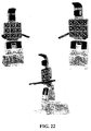
- an exemplary embodiment of multi-position support apparatus 10 features at least the following: back support 11, back-seat angle 13, seat 14, seat-leg angle 15, leg support 16, foot support 17, and multi-position support apparatus base 19. Moreover, multi-position support apparatus 10 optionally features at least one hand support 12 and leg-foot angle 18. Referring to FIG. 2 , other exemplary embodiments of the present invention feature back support 11 with or without length adjustment 22, and/or leg support 16 with or without length adjustment 21.
- back-seat angle 13, seat-leg angle 15, and leg-foot angle 18 feature a pivot, as known in the art.
- At least one actuator is connected to hand support 12.
- Multi-position support apparatus 10 uses engines to change its angular position. For decorative or space-saving purposes, multi-position support apparatus 10 can be designed with all or most of the engines controlling its angular position concentrated beneath seat 14.
- the electro-mechanical structure of multi-position support apparatus 10 of the present invention may be constructed in a variety of ways known in the art, and in the novel constructions as described in the following exemplary embodiments.
- multi-position support apparatus 10 when used for cleansing, both begins and ends in a standing position.
- multi-position support apparatus 10 The angles of multi-position support apparatus 10 are programmed so that the user returns to the standing position with maximum stability; slightly reclined. Because of its slightly reclined angle, multi-position support apparatus 10, when in a standing position, does not throw the user off-balance. It is to be understood that the meaning of "reclining” may be interpreted as “backward inclining.”
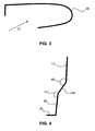
- FIG. 4 illustrates the angles of multi-position support apparatus 10 in standing position. Either in a standing position or when entering a standing position, angle 41 is larger than 180 degrees, in order to prevent the user from falling. Angle 40 should be smaller than 180 degrees, but not smaller than a predefined angle, which is dependent on the angular position of multi-position support apparatus 10 in its entirety.
- the control system of the system of the present invention prevents the user from manually reducing angle 40 to an angle wherein there exists a possibility that the user might fall forward from the multi-position support apparatus.
- the probability of an accident is very low. Receiving the user from a standing position, and, when the shower is completed, returning the user to a standing position, minimizes the probability of bathing/showering-related accidents occurring.
- the present invention is also useful for people who cannot stand.
- the present invention receives the user from a sitting position, and, when the shower is completed, returns the user to a sitting position.
- multi-position support apparatus 10 While in the reclining position, the user is securely supported by multi-position support apparatus 10 throughout the bathing process. Moreover, in the reclining position of multi-position support apparatus 10, the user remains in a relaxed position throughout the bathing process.
- FIG. 1 illustrates multi-position support apparatus 10, capable of entering into positions of standing, sitting and reclining.
- Engines are connected to the various parts of multi-position support apparatus 10. For example, engines are connected to back support 11, seat 14, and leg support 16. In another optional embodiment (not shown in the figure), there are engines connected to the device's pivots. For example, the two engines can be connected to back-seat angle 13 and seat-legs angle 15.
- the angle of back support 11, seat 14, and leg support 16 changes during operation in order to achieve maximum stability and put minimal pressure on the user's legs.
- the user enters the apparatus in a standing position, leans backwards, and upon achieving a reclined angle of 20 to 60 degrees, the apparatus begins to move the user into a sitting position.
- the apparatus moves from sitting to standing the user is first brought to a reclined position of between 20 and 60 degrees, and only then is brought to a full standing position.
- An exemplary embodiment of the present invention prevents a situation in which multi-position support apparatus 10 descends on the foot of an operator who is not the user, such as a nurse.
- One or more sensors are placed in or on foot support 17. The one or more sensors detect objects and prevent foot support 17 from crushing them.
- Optional sensors include, but are not limited to, infra-red sensor, electric footboard that sends a signal when it is stepped upon, micro switch, camera, or any other sensor known in the art.
- Another exemplary embodiment of the present invention prevents a situation in which back support 11 crushes an operator who is not the user, such as a nurse.
- One or more sensors are placed in or on back support 11. The one or more sensors detect objects and prevent back support 11 from crushing them.
- Optional sensors include, but are not limited to, infra-red sensor, electric footboard that sends a signal when it is stepped upon, micro switch, camera, or any other sensor known in the art.
- the armrests of the multi-position support apparatus of the present invention can move up, down, and to the sides, to enhance the user's comfort.
- the armrest can be detached from the multi-position support apparatus. In this case, when the multi-position support apparatus moves, the armrests do not move along with it, to allow the user to comfortably reach for an object or shelf during changes in position.
- FIG. 7 demonstrates an exemplary embodiment of a parallelogram-based structure device for shifting from sitting to reclining. The shift is made using a manual 70 lever, without the need for an engine.
- the parallelogram-based structure device can be locked in a certain angular position.
- the use of one engine and a parallelogram-based structure enables the multi-position support apparatus to shift from a standing to a sitting position, or from a sitting to a reclining position.
- Parts 80 and 90 operate a rod that can decrease or increase in length. When the rod's length grows, the device shifts to a reclining position.
- the leg-support and back-support move nearly together and therefore one engine can be used for both.
- the second engine is used for changing the angle of the multi-position support apparatus.
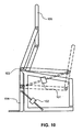
- FIG. 10 illustrates a parallelogram-based structure device with two engines.
- the operation of the first engine is identical to that of the parallelogram-based structure device with one engine.
- Operation of the second engine raises and lowers the device.
- 101 is an engine for shifting from a sitting to a standing position.
- the apparatus is fixed to axis 103.
- engine 102 The purpose of engine 102 is to shift the apparatus from a sitting to a lying position.
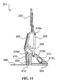
- FIG. 11 is an illustration showing the device of FIG. 8 with foot support.
- this exemplary embodiment of the present invention shows the states of engines 23, 24, and 25 setting the angular position of multi-position support apparatus 10.
- Use of three or more engines to control the angular position of multi-position support apparatus 10 enables further adjustment of the movement of multi-position support apparatus 10, for the comfort of the user.
- Multi-position support apparatus 10 may include more than three parts. Each part may feature a separate engine.
- Each part may feature a separate engine.
- two examples of optional parts (a) A headrest that can move up and down and change its angle in any of the three axes.
- An adjustable headrest is good for users with neck problems. The movement of the headrest can be controlled in conjunction with the operation of the bathing system. For example, when washing the hair, the headrest should tilt back.
- FIGS. 12-14 illustrate another exemplary embodiment of the multi-position support apparatus of the present invention featuring one engine. Changing the apparatus position from standing to reclining while using a single engine is a novel advantage of this embodiment.
- FIG. 12 illustrates an exemplary embodiment of multi-position support apparatus 201, featuring at least the following elements: back-support 200, seat 202, leg-support 204 with or without length extension 210, foot-support 206, multi-position support apparatus base 220, engine 214, rod 222, rod 224 and pivots 216a, 216b, 216c, and 216d.
- Engine 214 is connected to apparatus base 220 and moves rod 222 which is connected to seat 202.
- Rod 224 enables the movement of back-support 200.
- another engine (not shown in the figure) controls rod 224.
- engine 214 causes rod 222 to shorten, and thus seat 202 descends from a vertical to a horizontal position.
- Rod 224 shortens as well, optionally until reaching a stopper (not shown in the figure).
- angle 240 between leg-support 204 and an imaginary line perpendicular to the floor increases until reaching a predefined size, preferably between 30 and 60 degrees.
- Multi-position support apparatus 201 optionally features leg-support 204 with length extension 210 and wheel 212.
- the length of leg-support 204 is extended by length extension 210, until reaching a predefined length, at which point foot-support 206 may rise above floor level.
- the predefined length may be achieved by using a stopper.
- Wheel 212 enables foot-support 206 to move freely along the floor without experiencing unnecessary friction.
- length extension 210 may be motorized, and may move in accordance with the overall reclining action of multi-position support apparatus 201. It is to be understood that wheel 212 may by combined with all of the embodiments illustrated in the present invention.
- FIG. 14 illustrates the multi-position support apparatus in a sitting position. Shifting the apparatus from a sitting to a standing position is achieved by reversing the order of the aforementioned actions taken to shift from standing to sitting.
- engine 214 may be connected to any part of multi-position support apparatus 201 in combination with appropriate pivots and rods to achieve the capabilities of the device illustrated in FIG. 12 .
- engine 214 may be connected to back-support 200 or leg-support 204, while the pivots and rods are connected accordingly.
- engine 214 can be replaced by an engine connected to one of the pivots.
- multi-position support apparatus 10 is immersed in a bathtub or placed in a shower (not shown in the figures).
- multi-position support apparatus 10 features liquid conduits through which a liquid passes.
- the liquid may be used for bathing.
- Exemplary liquids are water, water with soap, bath oil, etc.
- the term “sprinkler” refers to any device that emits liquids including, but not limited to, water spreaders that are used for rinsing and/or bathing. e.g., jets, sprinkler jets, and nozzles.
- the user may be wet from multiple directions.
- the wetting process is done, at least partially, using sprinklers.
- all or some of the sprinklers can be placed on a device located on the side of multi-position support apparatus 10 (not shown in the figures).
- the device located on the side of multi-position support apparatus 10 may be similar to a device featuring sprinklers as known in the art of wall shower.
- the controller of the bathing device of the present invention may control the spray on the sprinklers placed on the device located on the side of multi-position support apparatus 10 in similar way to how it is controlling the sprinklers placed on multi-position support apparatus 10 itself.
- the sprinklers are either fixed in place, or movable/mobile/handheld.
- the sprinklers that wet the user's back are attached to back-support 11.
- the liquid can be sprayed through holes added to back support 11 that are large enough to allow for the passage of various liquids.
- the at least one sprinkler installed on the armrests can be a drop sprinkler, which provides, at least one more spraying direction than the number of spraying directions provided by available fixed sprinklers.
- multi-position support apparatus 10 may feature a plurality of massage elements that apply a massaging motion to the user.
- FIG. 15 and FIG. 16 illustrate an exemplary massage device for optional use with the present invention.
- the massage is given using two "fingers" that are connected to each other by a hinge. When one finger moves up, down or to the side, the other finger moves along with it.
- the massaging fingers are installed with freedom of movement in the up-down axis.
- This freedom of movement gives the user the feeling of a floating back and adjusts the structure of the chair to the structure of the user's back.
- the massaging device of the present invention may be installed in the seat, backrest and footrest.
- the massaging elements create a motion that improves cleansing by even distribution of liquids, as well as getting soap to body parts that the user cannot reach, or finds difficult to reach. In fact, the massaging fingers make it possible to soap all of the user's back without the user having to move.
- the massaging elements of the present invention increase circulation, which has a positive influence on the cardiovascular system.
- the massaging elements aid in the removal of dead skin cells, which when left unchecked can potentially cause the development of sebaceous cysts.
- multi-position support apparatus 10 features different lengths and therefore caters to users of various heights. Therefore, the length of multi-position support apparatus 10 should be adjusted to the height of the user. Adjustment of multi-position support apparatus 10 to the user's height may be accomplished by controlling the lengths of leg-support 16 and back-support 11.
- back-support length adjustment 22 featuring a telescopic device, used for adjusting the length of the back-support to accommodate the user's height.
- the telescopic device may be operated by one of the following: by hand, with a mechanical device, or using one or more engines, as known in the art.
- leg-support length adjustment 21 used for adjusting the length of the leg-support for the user's height, features a telescopic device.
- the telescopic device may be operated either manually or by engines, as known in the art.
- back support 62 is floating over back-support frame 60.
- the floating of back support 62 over back-support frame 60 is achieved by slides 61.
- one or more of the following parts may be floating parts: head support, back support, and leg support.
- the floating is achieved by using the following optional embodiments:
- a telescopic device is just an example and floating parts can be implemented with any other device known in the art, such as, but not limited to, the prior art wheelchairs disclosed in the background of the invention section of the present invention.
- the floating part's position on the slide is fixed. This can be achieved by using a pin, step motor, electromagnet, etc. In this case, the telescopic device is not needed, as the floating part is not moving independently.
- the floating device moves along at least one track. Options: a track down the middle, two tracks down the sides of the back-support, or any other equivalent implementation.
- a device moved by an engine over a track can be used instead of using a floating device. This is made possible due to the fact that the distance the user's back should move depends on the angular position of the chair/apparatus, and therefore can be measured in advance.
- the floating back-device moves together with the head support.
- the back-support can be divided into more than one part.
- the head-support is separated from the back-support, and thus becomes a multi-position support apparatus that is adjustable to different heights of users.
- the starting positions of the floating parts can be determined according to the specific user's height.
- the multi-position support apparatus of the present invention adjusts to different heights of users by moving the floating parts' positions according to the user's height. The taller a person is, the further apart the floating parts' starting position is in the apparatus' standing position.
- parts 11 and 14 are nearest to one another in a standing position.
- floating parts without active control.
- the floating parts are placed on a slide. When the user sits, parts 11 and 14 move away from one another. When the user lies down, parts 11 and 14 move closer together. To sum up, when shifting from a standing to a sitting position the parts should move away from each other, and when shifting from sitting to reclining the parts should move closer.
- the floating-parts solution as an exemplary method can be implemented on any of the users' body supporting parts, including the backseat and leg supports. Because relative movement is needed, it is sufficient that only the back-support part and/or the leg-support part be floating. In this case, it is not necessary for the seat to move, because the back-support and/or leg-support are moving.
- Every shower or bathtub has at least one water drain for collecting and draining liquids into a sewage system and/or into the appropriate disposal system.
- the multi-position support apparatus 10 positioned so that the water drain is located beneath foot-support 17. Thus, when multi-position support apparatus 10 is in the standing position, the water drain is neither exposed nor endangering the user.
- there is water drain features an electric pump that begins low-pressure draining of the liquids into the appropriate disposal system when the water level rises above a certain height. The purpose of the electric water pump is to prevent water from pooling in the shower.
- a feces-collecting device referred to herein as "integrated toilet" can be integrated into multi-position support apparatus 10.
- the integrated toilet features significant hygienic advantages.
- Exemplary integrated toilets include a toilet, toilet bowl, and lavatory seat.
- the outlet of the integrated toilet is directly connected to either, an appropriate disposal system or existing toilet basin.
- the integrated toilet may come with a bidet and/or sitz-bath, as known in the art.
- the toilet can be cleaned using either an existing shower spray hose, or device specified for this purpose.
- multi-position support apparatus 10 There are cases where there is a need to secure the user to multi-position support apparatus 10. For example, when the user is an elderly person suffering from Alzheimer's disease, dementia or amnesia. In either case, the user might try to get up during the washing procedure, and may fall down. In order to prevent injury, the user may be secured to the device.
- multi-position support apparatus 10 side-handles that close-in/envelop the user and hold the user in place, and/or support / stability / binding straps attached to the sides of multi-position support apparatus 10.
- FIG. 3 is an illustration of armrest 30, which enables the user of the present invention to enter multi-position support apparatus 10 from a comfortable and safe direction 31.
- Entering multi-position support apparatus 10 comfortably is achieved using two handles, armrests, or hand supports, featuring different lengths.
- On one side there is a short handle for allowing easy entry into the device; on the other side, a long handle both supports the user and prevents the user from falling from the apparatus.
- the user can be secured at the knees while standing, to increase safety and stability.
- Identifying the user may be achieved by any method known in the art. For example: by means of voice or visual aids, RFID, smart card, key, user's weight, control panel, etc.
- a personal program of a specific user is executed.
- parameters which can be saved in the personal program include duration of the shower, water temperature, soap types, shampoo types, number of shampoos, etc.
- the bathing system is operated by one or more controller-operated engines.
- Control of the engines, sprinkler heads, and other devices, such as the drying device can be operated by either the same controller or multiple controllers.
- the different controllers may be synchronized between themselves in order to improve the security and comfort of the user using the bathing system of the present invention.
- the controller of the bathing system of the present invention may be a preprogrammed controller.
- An angular position program operates the change in angular position of multi-position support apparatus 10. For example, changing from a standing position to sitting position, and from sitting to reclining backwards. Another example is changing from backwards reclining to sitting and standing.
- a bathing program which may be synchronized with the aforementioned angular position program is operating some or all necessary bathing devices, such as, but not limited to, water, inserting soap, rinsing, controlling temperature, and drying.
- the bathing system of the present invention is operated manually.
- the manual operating program activates each step/stage according to instructions from either the user or any other human operator.
- the bathing system of the present invention is operated by an automatic program that activates all stages, sequentially.
- the different bathing programs and their appropriate variables are stored in a memory device.
- the memory device may either be a part of the bathing system of the present invention or an external memory device.
- the bathing system is operated by one of the following, or by a combination thereof (a) the user, (b) an operator who is not the user, (c) from any place where it is possible to control the bathing system's operations via remote control or any other remote operating means as known in the art, or, (d) automatically, using methods known in the art.
- the bathing system of the present invention operates at least one predefined emergency response operation. For example, stopping the spraying of water over the user and bringing the user to a predefined angular position: standing, sitting, or reclining.
- the angular position, into which the user is brought in an emergency, is the most secure angular position for the specific user.
- it is possible to customize the bathing system of the present invention with the most secure position for each user. Entering the emergency response operation can be initialized by any kind of appropriate device, such as, but not limited to, emergency button, emergency pull-rope, voice command, etc.
- the bathing system activates a voice indicator that tells the user about the program to be executed. Only after the user confirms the voice-indicated selection does the bathing system activate the program.
- the user can confirm execution of the program by any input means known in the art, such as pressing a confirmation button, or by voice-command.
- the bathing system operates a selected program, according to a pre-defined period, in the event that a user does not confirm the selection.
- the bathing system cancels operation of a selected program, according to a pre-defined period, in response to a user not responding.
- the bathing system of the present invention activates one or more of the following operations:
- the bathing system of the present invention sends a warning signal to a predefined supervisor. For example, nurse or care center.
- the warning is transferred by means of communication known in the art.
- Communication means are, for example, voice, visual indication, telephone communications, or computer network.
- an exemplary bathing system of the present invention features an interface from which a variety of operations are controlled.
- the controller may be operated by the following exemplary means: manual, keyboard, voice-activation, computer-connected, for example via RS232 or USB, remote activation such as by telephone or wireless network, or by any other means known in the art.
- the bathing system of the present invention features a Built in Test (BIT).
- BIT Built in Test
- the BIT system may be used for fast identification of failures. This capability enables the technician to more easily determine what action should be taken when coming to the user. This also makes it easier to provide price quotes to the user prior to responding for repairs.
- the BIT results may be transferred to the technician's equipment via a phone line or wireless network, or any other know in the art communication aid.
- the technician When installing the bathing system at the user's site, the technician is able to set a combination of velocities, movement angles, liquid parameters, cleaning materials-related parameters, and other parameters referred to herein as "operational customized parameters" of the bathing system such that it is possible to fit the use of the bathing system to the requirements, comfort and safety of the specific user.
- the operational customized parameters are saved in a memory element for future use.
- introducing the steam is managed by either the bathing function or by manual operation.
- At least one pump is used, which controls the sprinklers' water pressure and supply, so that the performance of the washing device does not depend on exterior water pressure. This is especially useful whenever the external water pressure is low.
- the bathing system of the present invention contains a water tank for accumulating water before it is sprayed onto the user. The washing device begins washing the user only when the amount of water in the tank, combined with the estimated water pressure, is sufficient for completing the planned shower.
- the bathing system includes a temperature controller that immediately stops the spraying of liquid if it determines the liquid's temperature to be out of the predefined temperature range.
- the bathing system supports the integration of a fast-heating electric device. According to this option, the bathing system receives cold water and heats it to a preset temperature defined and controlled by a controller.
- a bypass hose is added, with an electric faucet and at least one temperature sensor.
- the at least one temperature sensor detects that the temperature of the water is not in the desired range, the water is directed to the Bypass Hose, which flows into the drain or to another place where the water will not touch the user.
- FIG. 5 An exemplary embodiment of the present invention, featuring high water flow, is illustrated in FIG. 5 .
- Tank 52 receives hot water 51 and cold water 50 from the water supply. The hot and cold water are mixed in the water tank. The temperature of the water in the tank is measured by means of one or more temperature sensor 53.
- a temperature sensor is installed close to the opening from which the tank water is pumped out by using pump 54.
- the amount of both hot and cold water filling the tank is controlled by a temperature controller (not shown in the figure) which reads a water temperature by using temperature sensor 53.
- the washing cycle can start.
- some amount of the water is fed into the bathing system by using pipe 56 and some amount of the water is fed back into the water tank by a back-feeding pipe 55.
- Returning some of the water back into the water tank enables operating the pump according to a constant flow.
- Operating the pump according to a constant flow may feature a few advantages such as a longer life cycle and less power consumption.
- a change in the water-line pressure has no influence on the bathing system of the present invention.
- the use of hot water received from outside of the bathing system enables the building up of high pressure even when water pumps are not connected to municipality water lines.
- the water tank and the pump are located at the base of the bathing system near the engines such that the structure of the bathing system in its entirety is aesthetic, while also occupying as little space as possible.
- the water temperature controller is synchronized with the overall bathing system controller. This synchronization enables the spraying of water at various temperatures over different parts of a user's body and changing the water temperature according to the different states of the system. For example, water sprayed over a user's head when it is being washed is less hot than water used to wash a user's back.
- a water- temperature-controller is connected to a bypass pipe. Whenever the temperature of the water fed into the bathing system by using pipe 56 is not within a predefined interval, the water are redirected to the bypass pipe.
- the bypass pipe may be connected to the drain or to the water tank.
- the temperature of the water and the amount and type of cleansing agent used by the bathing system of the present invention may be controlled by one or more bathing system controllers. Moreover, the temperature of the water and the amount and type of cleansing agent used by the bathing system of the present invention may be automatically, semi-automatically, or manually operated.
- a cleaning process of selected parts of the bathing system of the present invention occurs following predefined operations of the bathing system of the present invention.
- the cleaning process features at least one of the following: disinfecting, sanitation, sensing and drying the entire bathing system of selected part thereof.
- the user activates the cleaning process by means of the bathing system's sprinklers and dryer.
- a drying system specific for cleaning for example, toilet sprinklers.
- the cleaning process may be controlled by one or more bathing system controllers.
- the cleaning process may be automatically, semi- automatically, or manually operated.
- the dryers are able to dry the system of the present invention to such an extent that prevents the appearance of fungus and mildew.
- At least one of the parts used in multi-position support apparatus 10 is an ergonomic part. Ergonomic design enhances a user's safety and comfort while also increasing product usability.
- multi-position support apparatus 10 uses at least one controllable engine for setting the angular position of multi-position support apparatus 10 to make multi-position support apparatus 10 easy to learn, easy to use, aesthetically pleasing, and marketable. Moreover, multi-position support apparatus 10 increases the safety of the user and the efficiency of the treatment supplied to the user.
- the bathing system of the present invention is useful for paralyzed people in a wheelchair who need to start the action of multi-position support apparatus 10 from a sitting position in order to move easily onto multi-position support apparatus 10. For this purpose, it is possible to start the bathing system from a sitting position.
- the multi-position support apparatus 10 it is possible to adjust the multi-position support apparatus 10 to support users in need of extra space.
- Exemplary adjustment of the multi-position support apparatus to support users in need of extra space can be achieved by making a wider multi-position support apparatus or by expanding the distance between the armrests mechanically.
- Angular change that is to fast can cause dizziness in elderly people. This phenomenon is known in the art as orthostatic hypotension.
- the speed at which multi-position support apparatus 10 changes its angular position can be controlled and adjusted for the comfort and health condition of a user.
- it is possible to stop the apparatus by using the control panel or any other controlling device
- Some users are connected to infusions, are post-operative patients, or have external wounds. These people have body parts that should be covered to avoid contact with water.
- An exemplary feature of the bathing system of the present invention enables the covering of specific body parts to make the bathing process easier.
- the multi-position support apparatus of the present invention enables a personal cover, that can be cleaned or changed with ease, to be attached to or laid over the apparatus.
- a main benefit of the personal cover is the ability to operate the apparatus in a non-home environment with multiple users, in order to assure that a user is not contaminated by a previous user.
- data is collected on the use of the bathing system of the present invention.
- the bathing system is connected to software that tracks bathing times, the programs that have already been operated, and irregular occurrences such as entering a state of emergency.
- Such software is useful for senior citizens' and retirement homes, and other institutions that take care of elderly and disabled people, for collecting statistical data about the elderly.
- a heart monitoring device or electrocardiograph (ECG) device can be integrated into the bathing system of the present invention.
- ECG electrocardiograph
- the device detects unusual activity, the operation may be stopped. If there is a drastic change in heart rate, the bathing system of the present invention may activate and operate an emergency mode.
- a foot-bath device and/or a foot-massage device is integrated with foot support 17.
- foot-massage device is useful for example for diabetic and gout patients.
- foot-massage device is useful for people who suffer from corns, bunions, and general foot pain. Integrating a foot-bath with multi-position support apparatus 10 has many advantages. It is possible to use the water, drainage, and drying device of the bathing system of the present invention for the foot-bath, as well.
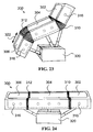
- Jacuzzi As is commonly known, bathing in a Jacuzzi offers many advantages. In order to achieve the Jacuzzi effect, the user and sprinklers must be immersed in water.
- a multi-position support Jacuzzi apparatus 300 in accordance with the present invention is capable of holding water like a bathtub.
- multi-position support Jacuzzi apparatus 300 is built as a bathtub having joints, which can bring the user from a standing to a lying position.
- the apparatus sidewalls retain a water level needed for immersing at least the back of the user and some of the sprinklers in water, and thus the Jacuzzi effect is made possible.
- the height of the sidewalls may be the same as the desired water level, but preferably, the sidewalls are higher than the water level in order to prevent water from spilling over unnecessarily.
- the water level in multi-position support Jacuzzi apparatus 300 is measured by an appropriate sensor and controlled by a controller.
- the water flow controller may be operated in a closed or open loop manner.
- multi-position support Jacuzzi apparatus 300 features a water pump and an air pump, thereby enabling the Jacuzzi sprinkles to provide both water flow and airflow as needed.
- multi-position support Jacuzzi apparatus 300 can hold enough water to immerse the user's back in water, it is similar to a bath system enabling operation of the sprinkles inside the water.
- water may spill out of multi-position support Jacuzzi apparatus 300 without interfering with the regular operation of multi-position support Jacuzzi apparatus 300, as new water is constantly flown in through sprinklers or other designated water openings.
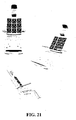
- At least one of the parts from the group featuring back-support, seat, leg-support, foot-support, and bath joints, is capable of holding water, either individually or in combination with other parts.
- FIGS. 23 and 24 illustrate an exemplary embodiment of multi-position support Jacuzzi apparatus 300, featuring at least the following: back-support 302, seat 304, leg-support 306, bath joints 310 and 312, sprinklers 316, and base and engines indicated by device 320.
- multi-position support Jacuzzi apparatus 300 when multi-position support Jacuzzi apparatus 300 is in its fully reclined position, back-support 302, seat 304, and leg-support 306 form a tub.
- the seat, back-support and their connecting joint form a water-holding vessel, while the leg support holds water separately.
- the seat and/or leg support each hold water separately, while the back-support does not hold water.
- Other formations are also possible.
- multi-position support Jacuzzi apparatus 300 may provide a Jacuzzi effect in other positions, such as a sitting or partially reclining position, and does not have to reach a fully horizontal position of 180 degrees. This may be achieved by multi-position support Jacuzzi apparatus 300 having a smart inner and/or outer construction.
- back-support 302 may be opened from the top and still retain water.
- Joints (310,312) of multi-position support Jacuzzi apparatus 300 may comprise rubber parts which are capable of changing shape or angle while retaining water in the apparatus tub.
- joints (310,312) may be shaped as a rubber accordion, capable of bending.
- joints (310,312) are able to retain water in the apparatus tub only when multi-position support Jacuzzi apparatus 300 is in its fully reclined position.
- device 320 actuates multi-position support Jacuzzi apparatus 300 of the present invention. It is to be understood that without limiting the scope of the present invention, novel multi position support Jacuzzi apparatus 300 may be actuated by any known in the art device and/or by the actuating devices disclosed in the present invention.
- the length of leg-support 306 may be adjustable, as indicated by reference 322.
- the length of leg-support 306 may change as the apparatus shifts from one position to another, for example - from a standing to a sitting position.
- multi-position support Jacuzzi apparatus 300 may feature a foot-support separate from the leg-support, and these parts may be connected by an appropriate joint.
- multi-position support Jacuzzi apparatus 300 may feature a head-support separate from the back-support, and these parts may be connected by an appropriate joint.
- FIG. 25 illustrates multi-position support Jacuzzi apparatus 300 in its standing position.
- Multi-position support Jacuzzi apparatus 300 may receive the user in a standing position, recline during the bath, and return the user to a standing position when the bathing is over.
- a foot Jacuzzi may be an integral part of multi-position support Jacuzzi apparatus 300, or may be attached to multi-position support Jacuzzi apparatus 300.
- the foot Jacuzzi operates when the feet are parallel to the floor, optionally, when the user is in a sitting position.
- a recess may be made in the floor beneath the foot-support.
- the recess can contain the Jacuzzi mechanism when multi-position support Jacuzzi apparatus 300 is in a standing position.
- the recess includes a water drain and may feature an electric pump that pushes the water into a disposal system in order to prevent the water from flooding the bathing area.
- Multi-position support Jacuzzi apparatus 300 has many advantages. For example, it enables elderly or disabled people to enjoy a Jacuzzi without facing the danger of slipping and the dangers caused by awkwardly entering a regular shower. Additionally, the fact that the user's head may be safely kept out of the water during bathing enables elderly people and people suffering from drowsiness to enjoy a Jacuzzi.
- spring elements surface is used for seat and/or back rest and/or legs support and/or head support and/or any other surface bearing some of the user's body weight.
- novel spring elements surface of the present invention may be integrated with all above-described prior art devices, and especially with the novel multi-position support apparatus, such as multi-position support apparatus 10 illustrated in FIG 1 .
- FIG. 21 and FIG. 22 are exemplary multi-position support apparatus featuring spring elements surface, in accordance with the present invention.
- novel spring elements surface of the present invention may be placed on any support apparatus used for bathing application.
- any support apparatus used for bathing application For example, bathing chair, bathing bed, and bathing slanted support surface.
- the spring elements surface features a plurality of elastic spring elements.
- the elastic spring elements are leaf shaped as known in the art. The shape, size and number of elastic spring elements provide sufficient support to the body weight of the user.
- the spring elements surface of the present invention may be made of any known in the art material as long as the required resilient characteristics are achieved.
- the spring elements can be disposed adjacent each other in any manner as long as it is simply guaranteed that a suitable force transference to achieve the desired spring comfort, that is to say the impression of sitting on something soft on the seat, is guaranteed.
- the spring elements surface features the following parts: (a) a fenestrated support area that supports the body weight, (b) at least one spring element, and (c) connecting area to the supporting apparatus.
- the support area is the area on which the user leans.
- the support area is upholstered, as illustrated in FIG. 19 by reference 408.
- Fenestrated support area 408 may be produced in all sizes and shapes, such as, for example, rectangular, square, oval, round, triangular and so on.
- FIG. 20 illustrates an exemplary preferred embodiment of the present invention featuring fenestrated support area.
- the fenestrated support area should cover as less body area as possible, as long as the spring elements surface is still comfortable enough. Covering as less body area as possible enables an easy spraying of liquid on the user's body.
- the spring element of the spring elements surface of the present invention should comfortably absorb the body weight of the user while disturbing as less as possible to the liquid spraying, as illustrated, for example, by reference 406 in FIGS. 17-19 .
- the spring elements are resiliently deformable, where required, individually, independent of each other. In case where the sprinkler is placed in the connecting area, it is possible to easily spray the liquids over the users body.
- the spring elements are designed like a leaf spring and feature a connecting area to the supporting apparatus.
- the connecting area to the supporting apparatus serves to attach the spring element to the support apparatus and/or to designated supporting device.
- the connecting area to the supporting apparatus are detachable and/or enabling the use of appropriate fastening devices, such as screws, rivets and clip elements.
- the spring of the present invention may be produced in various ways.
- Bock discloses an elastic spring element designed like a leaf spring and comprising a connecting area, a support area as well as a spring element area coupling the connecting area with the support area.
- the connecting area serves the fastening of the leaf spring to the respective lying surface.
- the connecting area may contain, for example, a receiving feature in the form of a through-hole, through which a fastening device, such as a screw, can be guided and screwed in.
- the connecting area may comprise fast snap-fit elements, which are inserted into corresponding recesses or placed onto corresponding projections.
- arranging a plurality of leaf springs creates an extensive support area.
- the leaf spring is attached to the surface at only one spot in rounded connection; the rounded connection gives the spring ability to resiliently bend over in all directions of the surface, the bending angle covers 360 degrees of the surface.
- the leaf spring can bend horizontally and/or vertically over the surface.
- the leaf spring can bend to the depth of the surface.
- Each leaf spring element is individually adjustable to the amount and direction of the force applied by the user's body weight. For example, when placing a number of leaf spring elements in back rest device, the leaf springs adjust to support the back of the user.
- spring devices can exhibit different levels of spring stiffness so that not only spring elements with the different spring stiffness levels can be combined individually with each other, but also that it offers the possibility of adjusting a spring element in terms of its spring stiffness. Different spring stiffnesses enable better support for sensitive body parts like the head.
- the extensive support of the novel spring elements surface of the present invention provides maximum comfort, and there is no need to add a mattress on top of the spring element surface.
- the comfort of the surface enables the user to lean on the spring element surface without clothing, with bare skin, without feeling uncomfortable.
- Using the spring elements surface without any cover or mattress provides better hygienic use in public places, because cleaning the surface is easier and faster after every use.
- covering the spring elements surface with a sheet or another cover may also provide better hygienic use, because the cover can easily be replaced between different users.
- the spring elements surface is used for bathing applications.
- a sprinkler is attached to the connecting area to the supporting apparatus.
- the spring element should be designed to have such a shape that enables maximum spreading of the liquid from the sprinkler.
- FIGS. 17-20 illustrate an exemplary shape which features very good liquid spreading performances.
- the sprinklers are placed behind the spring elements surface, or even behind the support apparatus.
- the leaf spring covers a small percentage of the user's body surface, thus enabling good bathing.
- a leaf spring may be preferred over using other shapes of springs such as a spiral spring.
- the leaf spring is preferred over the other spring shapes because it features a minimal supporting area and the shape of the spring elements of the leaf spring ensures better spreading of the liquid over the user's body.
- the leaf spring surface better distributes the weight of the user's body because the spring elements are able to bend in every direction, so the surface is more comfortable and can be used without clothing.
- the leaf spring covers a small percentage of the user's body surface, thus enabling optimal spread of the bathing liquid on the user's body and better bathing.
- the spring elements surface can be made of springs having different size and/or stiffness which provides the best comfort level according to the surface size.
- the spring suspension surface of the present invention does not lose its outer shape under compressive load as the pressure is absorbed by the fashioning of the individual spring members.
- the bathing system featuring at least one spring elements surface of the present invention receives and releases a user in a completely upright standing position.
- the multi-position support apparatus may feature a seat pivotally attached to a back support and a leg support, wherein the back support, the seat and the leg support are adjustable relative to one another, such that the multi-position support apparatus is adjustable between reclining, sitting and standing positions, wherein in the standing position the back support, the seat support and the leg support are all generally vertical.
- a multi-position support apparatus may feature a calf support and a foot support.
- the seat may include a pair of buttock supports.
- Liquids conduits may be included for passing a cleansing liquid directed toward the groin area of a user sitting in the multi-position support apparatus.
- a head-bathing device may be attached to an upper portion of the back support, with liquid conduits for passing a cleansing liquid directed towards the scalp of a user sitting in the multi-position support apparatus.
- the seat may be pivotally attached to a base.
- a drying device may be mounted on the back support, the seat, the leg support and/or the head-bathing device, to direct drying air at a user sitting in the multi-position support apparatus.
Abstract
Description
- This application claims priority to
US patent application number 11/130129US Patent Application number 11/130130US Provisional Patent Application number 60/715147US Provisional Patent Application number 60/715177US Provisional Patent Application number 60/738592 - The present invention relates to bathing and, more particularly, to a bathing system featuring a multi-position support apparatus and, optionally, controller operated sprinklers and massage elements.
- Hereinafter, the term "sprinkler" refers to any device that emits liquids, including, but not limited to, water spreaders that are used for rinsing and/or bathing. For example, jets, sprinklers jets, and nozzles.
- Hereinafter, the term "bathing" refers to any device that cleans a user by using water and/or other ingredients, including, but not limited to, washing, and showering. It is to be understood that the bathing system of the present invention includes a showering system and a cleaning system of any type.
- Hereinafter, the term "engine" refers to any device that is able to move things, including, but not limited to motor, and actuator.
- Basic principles and details relating to bathing system and corresponding method needed for properly understanding the present invention are provided herein. Complete theoretical descriptions, details, explanations, examples, and applications of these and related subjects and phenomena are readily available in standard references in the fields of physics, electronics, home care devices, and elderly care.
- There is prior art regarding elements, systems, and methods based on, or including, multi-position wheelchairs and multi-position beds. However, none of the prior art refers to bathing systems featuring multi-position support apparatus, or includes the important and novel feature of both beginning and ending a bathing operation from a standing position. Additionally, none of the prior art refers to bathing systems featuring spring elements surface.
-
U.S. Patent No. 5465437, issued to Herman William David , describes a bathing appliance which enables a handicapped person to wash comfortably and safely inside a shower stall or in a bathtub. The appliance includes a base frame constructed to rest firmly on the floor of a stall or bathtub, and a chair seat on which the handicapped person can sit when entering and leaving the bathing enclosure and while washing inside the enclosure. The chair seat has a first swivel mechanism fixed to a bottom portion of the seat to allow the seat to be supported for relative movement over the base frame. The base frame has a second swivel mechanism that forms a fixed base pivot axis normal to the floor of the bathing enclosure. An extension arrangement has a third swivel mechanism at a top end for engaging the first swivel mechanism of the chair seat, for swiveling movement about an extension axis parallel to the base pivot axis. The extension arrangement also has a fourth swivel mechanism at the bottom end for engaging the second swivel mechanism of the base frame, for swiveling movement about the base pivot axis. The extension arrangement is constructed to support the chair seat above the base frame, while allowing the seat to move between positions outside the bathing enclosure where the person can mount or dismount the seat, and positions inside the bathing enclosure where the person can bathe comfortably while seated. However, by definition, is unable to achieve a standing position. Also, there is no user customization and no preprogrammed operation programs. -
U.S. Patent No. 6003168, issued to Steadman William David , describes an apparatus for moving a person into and out of a bath. The apparatus is comprised of a seat mounted by pivotal linkages. The seat can be raised using a ram. The linkages are arranged such that when the seat is raised beyond a particular height the seat tilts rearwardly whereby to raise the legs of a person on the seat to permit same to be pivotted over the side of a bath without the requirement of lifting the seat far above the bath. However, it is unable to achieve fully horizontal or standing positions. Also, there is no embodiment with an integrated bathing system, nor monitoring and control with preprogrammed operation programs. -
U.S. Patent No. 5287568, issued to Mohrmann Gene D , describes a tilt lift bathing system which includes a central support having a chair mounted thereon for pivotal movement about a horizontal pivot axis between a lowered upright position adjacent one side of the central support and a raised recumbent position above the central support. The chair is rotatable about a vertical axis in its raised recumbent position so that upon mounting of the central support adjacent one wall of a bathtub, the chair is pivotable upwardly by a powered device to the raised recumbent position rotatable over the tub wall and pivotable downwardly to the lowered upright position in the tub for bathing an occupant of the chair. However, it is unable to achieve fully horizontal or standing positions. Also, there is no embodiment with an integrated bathing system, nor monitoring and control with preprogrammed operation programs. -
U.S. Patent No. 5517704, issued to Dagostino Richard J. , describes a combined commode and shower chair apparatus comprised of: a base section; a seat section adapted to rest on the base section; and an outrigger section removably attachable to the base section. The seat section is slidable from the base section onto the outrigger section for transferring a person in the seat section over a standard bathtub for taking a shower. However, 5517704 is unable to achieve a standing position. However, the unit does not move from a standing position to a lying position or a standing position. Also, there is no user customization and no preprogrammed operation programs. -
U.S. Patent No. 5287568, issued to Mohrmann, Gene D , describes a tilt lift bathing system includes a central support having a chair mounted thereon for pivotal movement about a horizontal pivot axis between a lowered upright position adjacent one side of the central support and a raised recumbent position above the central support. The chair is rotatable about a vertical axis in its raised recumbent position so that upon mounting of the central support adjacent one wall of a bathtub, the chair is pivotable upwardly by a powered device to the raised recumbent position rotatable over the tub wall and pivotable downwardly to the lowered upright position in the tub for bathing an occupant of the chair. However, the control unit does not move to a standing or lying position. There is no description or suggestion for a massage-related embodiment and/or use. Also, there is no user customization and no preprogrammed operation programs. -
U.S. Patent 5465437, issued to Herman, William David , describes a bathing appliance which enables a handicapped person to wash comfortably and safely inside a shower stall or in a bathtub. The appliance includes a base frame constructed to rest firmly on a floor of the stall or bathtub, and a chair seat on which the handicapped person can sit when entering and leaving the bathing enclosure and while washing inside the enclosure. The chair seat has a first swivel mechanism fixed to a bottom portion of the seat to allow the seat to be supported for relative movement over the base frame. The base frame has a second swivel mechanism that forms a fixed base pivot axis normal to the floor of the bathing enclosure. An extension arrangement has a third swivel mechanism at a top end for engaging the first swivel mechanism of the chair seat, for swiveling movement about an extension axis parallel to the base pivot axis. The extension arrangement also has a fourth swivel mechanism at the bottom end for engaging the second swivel mechanism of the base frame, for swiveling movement about the base pivot axis. The extension arrangement is constructed to support the chair seat above the base frame, while allowing the seat to move between positions outside the bathing enclosure where the person can mount or dismount the seat, and positions inside the bathing enclosure where the person can bathe comfortably while seated. However, it is unable to achieve fully horizontal or standing positions. Also, there is no embodiment with an integrated bathing system, nor monitoring and control with preprogrammed operation programs. And there is no description or suggestion for a massage-related embodiment and/or use. -
U.S. Patent No. 3964786, issued to Mashuda David describes a wheelchair in which the seat, back and leg portions are so articulated and separately actuable, by power means, under control of the occupant, as to enable the occupant to assume any one of three positions; namely sitting, standing or reclining. Two separated leg support members are selectively actuable by the occupant to a horizontal leg-supporting position. Steering, and forward and reverse propulsion, controls accessible to the occupant are also provided, enabling the occupant to obtain substantially total mobility on level ground. However, there is no description or suggestion for a bathing related embodiment, no user customization and no preprogrammed operation programs. -
U.S. Patent No. 4105242, issued to Terbeek Howard G , describes a cart, convertible between a chair position and a bed position, which includes a horizontal seat frame pivotally coupled to a leg rest frame, a back frame, and four depending legs. The forward-most pair of the depending legs and the back frame are coupled by an adjustment means for simultaneously raising the forward pair of legs and lowering the back frame toward a horizontal position, thereby facilitating rolling the cart onto a raised platform having limited vertical clearance such as onto the loading gate of a station wagon. The rearward most pair of the depending legs can also be raised toward a horizontal position, thereby facilitating positioning of the entire cart on the raised platform. However, there is no description or suggestion for a bathing- related embodiment and no automatic user customization and no preprogrammed operation programs. - European Patent No.
0558858A1 issued to Bessiere, Noel describes a convertible seat/stretcher especially for handling or transporting incapacitated patients - it has articulated back, seat and leg rest sections on side frames, allowing adjustment between standing, sitting and lying positions. It has an armchair which can be transformed into a bed or a stretcher and comprises a backrest, a seat part and a leg rest, bracing a set of two rectangular lateral frames, hinged at their tops and integral in their deformation, of which the front sides and rear sides are extended respectively upwards and downwards in order to form the lateral reinforcements of the backrest, and of the leg rest; and of which the lower sides form the lateral reinforcements of the seat part, and of which the upper sides are each hinged about a horizontal hinge pin,, normally perpendicular to the vertical planes passing through the said frames, and integral with a base resting on the ground, this armchair being characterized in that the hinge pin of the upper side of a frame is arranged either below or above the said upper side at a distance from the latter not exceeding 10 centimeters. This armchair is intended more particularly for the handling, transporting, laying down and seating of disabled or able-bodied persons who are to be examined or operated on. However, there is no description or suggestion for a bathing-related embodiment, nor for motorized positioning control, nor for the supportive adjustable footrest, which adjusts automatically for changes in position; also, there is no user customization and no preprogrammed operation programs. -
U.S. Patent No. 5366036, issued to Perry, Dale E describes a wheelchair apparatus provided for selectively positioning the operator from a sitting position to a standing position or a reclining position. The wheelchair apparatus includes a frame for supporting the operator's body in a reclined, sitting, and standing position. A single positioning actuator is used to selectively move the operator in the frame. A programmable controller controls the operation of both the chassis drive motors and the positioning actuator. The frame and chassis components are interconnected to achieve the desired positioning with a minimum number of electro-mechanical components. A sliding back frame is provided to eliminate shear forces on the back of the operator. The foot rest and frame are shifted towards the rear of the wheelchair when the operator is moved to a standing position such that the weight of the operator is over the axis of the large front wheels. A shock absorber is attached to the back frame to minimize any instability in the back of the apparatus and to provide additional lifting force in the reclining position. A parallel linkage arm is provided for moving the control station to the side of the wheelchair. When changing positions the ofUS5366036 , the seat back may have a tendency to produce a shear force against the back of the wheelchair operator. The shear force pulls on the clothes of the operator and irritates the skin by providing a sliding back with virtually zero shear. The inner back frame and the outer back frame are slidably connected to eliminate the shear stresses on the back of the operator. The body frame includes a slidable base which shifts the weight of the body frame and the operator to the rear of the wheelchair when the wheelchair is transformed from the sitting position to the standing position. However, there is no description or suggestion for a bathing related embodiment, no user customization and no preprogrammed operation programs. -
U.S. Patent No.4407543, issued to Mashuda, David , describes improvements in a mechanized wheelchair in which the seat, back and leg members are so linked and articulated on a body frame as to enable the occupant to assume any one of three positions; namely sitting, standing or reclining. By movably mounting the body frame on a base frame the height may also be controlled in conjunction with the above positions. A drive means is also provided. However, there is no description or suggestion for a bathing related embodiment, no user customization and no preprogrammed operation programs. There is also no user customization and no preprogrammed operation programs. -
U.S. Patent Application No. 20040210155A1, issued to Takemura Yasuhiro et al. , describes a monitoring device which can detect conditions of a sleeping person. A monitoring device comprising: multiple independent distance sensors installed facing different positions in a monitored target area to be monitored for measuring a distance to a monitored target, a calculating unit for calculating changes over time in the outputs of the distance sensors, and a detection processor for detecting changes in shape of the monitored target based on the calculated changes over time in one or multiple distance sensor among the multiple distance sensors. However, there is no description or suggestion for a bathing-related embodiment and/or use. Also, there is no user customization and no preprogrammed operation programs. -
U.S. Patent Application No. 20040004559A1, issued to Rast Rodger H , describes a system allowing persons to operate their computer comfortably while lying in bed. The system has a keyboard that provides pre-selection feedback indicating prior to a keystroke being entered, thus allowing the individual to verify the correct key before pressing down the key. Additional aspects of the system include the user of display goggles with panning control, and a see-through mode. In addition, there is a keyboard having multiple keys that upon being pressed past a selection threshold generate a keystroke for entry into the current application, wherein the improvement comprises: means of sensing intermediate key pressure which is less than that required to generate a selection; and programming in the application for generating feedback as to which key is subject to the intermediate pressure, wherein the user can change hand positioning to find the desired key before entering a keystroke. However, there is no description or suggestion for a bathing-related embodiment and/or operation of a multi-position support apparatus -
U.S. Patent No. 6131868, issued to Welling, Jeffrey R describes a communication and control device for attachment to the head end of a hospital bed for positioning a voice activated communication and control module adjacent a patient's head. The device comprises an arm having first, second and third arm segments, with first and second articulating joints connecting the first and second and second and third arm segments respectively. A securing mechanism releasably secures the first arm segment to the bed, and a third articulating joint connects the first arm segment to the securing mechanism. The first articulating joint accommodates electrical transmission wire substantially within the joint. However, there is no description or suggestion for a bathing-related embodiment and/or use, and the bed is unable to achieve a standing position. Also, there is no user customization and no preprogrammed operations programs. -
U.S. Patent No. 6781517, issued to Moster, Jeffrey A. , discloses a communication and control apparatus which includes a control unit having a surface accessible to a person on a bed, the control unit being coupled to a portion of the bed. However, the controls unit does not move the bed from a standing position to a lying position through a sitting position. There is no description or suggestion for a bathing-related embodiment and/or use. Also, there is no user customization and no preprogrammed operation programs. -
U.S. Patent No. 4885810, issued to Unger Gregory T , describes a litter for assisting disabled patients in getting in and out of hydrotherapeutic pools. The litter moves progressively from a chair-like position for the patient to sit on, to a horizontal position in which the patient is supported in a supine position, to a position in which the litter is cantilevered over the pool and finally into a substantially vertical position in which the free end of the litter and the patient are submerged within the pool. The progressive movements of the litter are reversed to remove the patient from the pool. However, there is no embodiment with an integrated bathing system, nor monitoring and control with preprogrammed operation programs. And there is no description or suggestion for a massage-related embodiment and/or use. -
U.S. Patient No. 4119164, issued to Fogg Jr et al. , describes a wheelchair which enables an invalid to stand, sit or choose at any intermediate position to perform useful work, and to move about in any of said positions. The wheelchair helps to fulfill the psychological and physiological needs of handicapped persons. The lifting and lowering operations are so arranged that practically no dislocation of the invalid's clothes occurs during the operations. However, there is no description or suggestion for a bathing related embodiment, no description or suggestion for active control of the floating back support, no description or suggestion for user customized floating back, and no description or suggestion for floating legs support. -
US 2, 576, 623 discloses a bath tub hingedly mounted on a collapsible stand.US 2,576,623 proposes provision of a patient board for moving the patient from the bed into the tub and also for moving the patient from the tub into the bed. This patient board can be of marine plywood and of expeditiously chosen size so as to fit within the tub and so as to support an average, bigger then average and smaller than average patient. -
WO 1997 32510 - To date, the inventor is unaware ot prior art teaching of a bathing system and corresponding method featuring a multi-position support apparatus accepting a user in a standing position, moving the user into a predefined reclining position, bathing the user in that predefined reclining position, and returning the user to a standing position
- Moreover, the inventor is unaware of prior art teaching of a bathing system and corresponding method featuring spring elements surface.
- Moreover, the inventor is unaware of prior art teaching of a multi position support apparatus featuring spring elements surface.
- Moreover, the inventor is unaware of prior art teaching of a multi position support apparatus featuring a Jacuzzi effect.
- All of the aforementioned patents do not contain the features inherent in the present invention. The novel bathing-related embodiments of the present invention with adjustable supportive footrests, variable pressure, temperature control, preprogramming options, and communications capability, are unique to the present invention. Additionally, all of the aforementioned prior art patents do not contain the novel spring elements surface of the present invention.
- There is thus a need for, and it would be highly advantageous to have a bathing system and corresponding method featuring a multi-position support apparatus and, optionally, controller operated sprinklers and massage elements.
- Moreover, there is a need for such a method which is significantly safer, automatic, and therefore, more cost effective, than currently used bathing solutions.
- Furthermore, there is a need for a bathing system that is able to move between reclining and sitting positions.
- Moreover, there is a need for a bathing system that is adjustable between sitting and standing positions.
- Moreover, there is a need for controlling the temperature of the sprayed water.
- Moreover, there is a need for a bathing system featuring a water pump operated in a constant flow.
- Moreover, there is a need for, and it would be highly advantageous to have a bathing system and corresponding method featuring a spring elements surface.
- Moreover, there is a need for such a method which is significantly cleaner than currently used bathing solutions.
- Moreover, there is a need for and it would be highly advantageous to have a bathing system and corresponding method featuring spring elements surface.
-
GB 2 340 388 - The present invention relates to a bathing system featuring a multi-position support apparatus and, optionally, controller operated sprinklers and massage elements.
- Thus, according to the present invention, there is provided a bathing system including: (a) at least one multi-position support apparatus able to change its angular position, and (b) at least one sprinkler.
- The present invention for bathing system successfully address limitations of presently available bathing devices. The method of the present invention is readily implemented using standard hardware components and standard software modules. Moreover, the system of the present invention is generally applicable as a 'stand-alone' bathing system, or as a bathing system used in combination with other methods, devices, and systems, performing washing operations.
- Implementation of the bathing system of the present invention involves performing or completing selected tasks or steps manually, semi-automatically, fully automatically, and/or a combination thereof. Moreover, depending upon actual instrumentation and/or equipment used for implementing a particular preferred embodiment of the disclosed system, several embodiments of the present invention could be achieved by hardware, by software on any operating system of any firmware, or a combination thereof. In particular, as hardware, embodiments of the invention could exist by variations in the physical structure. Additionally, or alternatively, as software, selected functions of the invention could be performed by a data processor, such as a computing platform, executing a of computer program types of software instructions or protocols using any suitable computer operating system.
- The present invention is herein described, by way of example only, with reference to the accompanying drawings. With specific reference now to the drawings, it is stressed that the particulars shown are by way of example and for purposes of illustrative discussion of the preferred embodiments of the present invention only, and are presented in order to provide what is believed to be the most useful and readily understood description of the principles and conceptual aspects of the present invention. In this regard, no attempt is made to show structural details of the present invention in more detail than is necessary for a fundamental understanding of the invention, the description taken with the drawings making apparent to those skilled in the art how the several forms of the invention may be embodied in practice. Identical structures, elements or parts which appear in more than one figure are preferably labeled with a same or similar number in all the figures in which they appear. In the drawings:
-
FIG. 1 is a schematic illustration of multi-position support apparatus in accordance with the present invention; -
FIG. 2 is a schematic illustration of multi-position support apparatus featuring adjustable length ; -
FIG. 3 is a schematic illustration of an arm rest ; -
FIG. 4 is a schematic illustration of exemplary preferred angles in accordance with the present invention; -
FIG. 5 is a schematic illustration of a high water flow device ; -
FIG. 6 is a schematic illustration of a floating back support ; -
FIG. 7 is a schematic illustration of a manually operated multi-position support apparatus ; -
FIG. 8 is a schematic illustration of a multi-position support apparatus featuring one engine in accordance with the present invention; -
FIG. 9 is another schematic illustration of a multi-position support apparatus featuring one engine in accordance with the present invention; -
FIG. 10 is a schematic illustration of a multi-position support apparatus featuring two engines ; -
FIG. 11 is another schematic illustration of a multi-position support apparatus featuring two engines; -
FIG. 12 is a schematic illustration of a multi-position support apparatus featuring one engine in accordance with the present invention; -
FIG. 13 is another schematic illustration of a multi-position support apparatus featuring one engine in accordance with the present invention; -
FIG. 14 is another schematic illustration of a multi-position support apparatus featuring one engine in accordance with the present invention; -
FIG. 15 is a schematic illustration of a massage device ; -
FIG. 16 is another schematic illustration of a massage device ; -
FIG. 17 is an exemplary prior art leaf spring element; -
FIG. 18 is another exemplary prior art leaf spring element; -
FIG. 19 is a schematic illustration of the novel upholstered spring element ; -
FIG. 20 is an exemplary spring elements surface -
FIG. 21 is an exemplary multi-position support apparatus featuring spring elements surface; and -
FIG. 22 is another exemplary multi-position support apparatus featuring spring elements surface; -
FIG. 23 is a schematic illustration of a multi-position support Jacuzzi apparatus ; -
FIG. 24 . is another schematic illustration of a multi-position support Jacuzzi apparatus; and -
FIG. 25 is another schematic illustration of a multi-position support Jacuzzi apparatus; - The present invention relates to bathing and, more particularly, to a bathing system featuring a multi-position support apparatus and, optionally, controller-operated sprinklers and massage elements.
- In an exemplary embodiment of the present invention, the bathing system of the present invention receives and releases a user in a completely upright standing position. Moreover, the present invention discloses a multi-position support apparatus featuring a seat support pivotally attached to a back support and a leg support, wherein the back support, the seat support and the leg support are adjustable relative to one another, such that the multi-position support apparatus is adjustable between reclining, sitting and standing positions, wherein in the standing position the back support, the seat support and the leg support are all generally vertical. Moreover, a multi-position support apparatus may feature a calf support and a foot support. The seat support may include a pair of buttock supports. Liquids conduits may be included for passing a cleansing liquid directed toward the groin area of a user sitting in the multi-position support apparatus. Moreover, a head-bathing device may be attached to an upper portion of the back support, with liquid conduits for passing a cleansing liquid directed towards the scalp of a user sitting in the multi-position support apparatus. The seat support may be pivotally attached to a base. Moreover, a drying device may be mounted on the back support, the seat support, the leg support and/or the head-bathing device, to direct drying air at a user sitting in the multi-position support apparatus.
- The bathing system of the present invention is based on the novel multi-position support apparatus disclosed herein and on the novel combination of a multi-position support apparatus and bathing system.
- The present invention is a system. The preferred embodiments of the present invention are discussed in detail below. It is to be understood that the present invention is not limited in its application by the details of the order or sequence of steps of operation or implementation of the method and/or the details of construction, arrangement, and composition of the components of the device set forth in the following description, drawings or examples. While specific steps, configurations and arrangements are discussed, it is to be understood that this is done for illustrative purposes only. A person skilled in the relevant art will recognize that other steps, embodiments, configurations and arrangements can be used without departing from the scope of the present invention.
- The present invention is capable of other embodiments or of being practiced or carried out in various ways. Also, it is to be understood that the phraseology, terminology and notation employed herein are for the purpose of description and should not be regarded as limiting.
- Configurations, components, operation, and implementation of the bathing system of the present invention, are better understood with reference to the following description and accompanying drawings.
- Referring to
FIG. 1 , an exemplary embodiment ofmulti-position support apparatus 10, features at least the following: backsupport 11, back-seat angle 13,seat 14, seat-leg angle 15,leg support 16,foot support 17, and multi-positionsupport apparatus base 19. Moreover,multi-position support apparatus 10 optionally features at least onehand support 12 and leg-foot angle 18. Referring toFIG. 2 , other exemplary embodiments of the present invention feature backsupport 11 with or withoutlength adjustment 22, and/orleg support 16 with or withoutlength adjustment 21. - In an exemplary embodiment of the present invention, back-
seat angle 13, seat-leg angle 15, and leg-foot angle 18 feature a pivot, as known in the art. - In another exemplary embodiment of the present invention, at least one actuator is connected to
hand support 12. - In the following description of the method of the present invention, included are only main or principal details needed for sufficiently understanding proper 'enabling' utilization and implementation of the disclosed system and corresponding method. Accordingly, descriptions of the various required or optional minor, intermediate, and/or sub systems which are readily known by one of ordinary skill in the art, which are available in the prior art and technical literature relating to bathing activities are not included herein.
-
Multi-position support apparatus 10 uses engines to change its angular position. For decorative or space-saving purposes,multi-position support apparatus 10 can be designed with all or most of the engines controlling its angular position concentrated beneathseat 14. - The electro-mechanical structure of
multi-position support apparatus 10 of the present invention may be constructed in a variety of ways known in the art, and in the novel constructions as described in the following exemplary embodiments. - In an exemplary embodiment, when used for cleansing,
multi-position support apparatus 10 both begins and ends in a standing position. - The angles of
multi-position support apparatus 10 are programmed so that the user returns to the standing position with maximum stability; slightly reclined. Because of its slightly reclined angle,multi-position support apparatus 10, when in a standing position, does not throw the user off-balance. It is to be understood that the meaning of "reclining" may be interpreted as "backward inclining." -
FIG. 4 illustrates the angles ofmulti-position support apparatus 10 in standing position. Either in a standing position or when entering a standing position,angle 41 is larger than 180 degrees, in order to prevent the user from falling.Angle 40 should be smaller than 180 degrees, but not smaller than a predefined angle, which is dependent on the angular position ofmulti-position support apparatus 10 in its entirety. - The control system of the system of the present invention prevents the user from manually reducing
angle 40 to an angle wherein there exists a possibility that the user might fall forward from the multi-position support apparatus. - During bathing/washing actions (i.e. during the shower itself) with the bathing system of the present invention, the probability of an accident is very low. Receiving the user from a standing position, and, when the shower is completed, returning the user to a standing position, minimizes the probability of bathing/showering-related accidents occurring.
- It is to be understood that the present invention is also useful for people who cannot stand. In that case, the present invention receives the user from a sitting position, and, when the shower is completed, returns the user to a sitting position.
- While in the reclining position, the user is securely supported by
multi-position support apparatus 10 throughout the bathing process. Moreover, in the reclining position ofmulti-position support apparatus 10, the user remains in a relaxed position throughout the bathing process. -
FIG. 1 illustratesmulti-position support apparatus 10, capable of entering into positions of standing, sitting and reclining. - Engines are connected to the various parts of
multi-position support apparatus 10. For example, engines are connected to backsupport 11,seat 14, andleg support 16. In another optional embodiment (not shown in the figure), there are engines connected to the device's pivots. For example, the two engines can be connected to back-seat angle 13 and seat-legs angle 15. - The angle of
back support 11,seat 14, andleg support 16, changes during operation in order to achieve maximum stability and put minimal pressure on the user's legs. In an exemplary embodiment, the user enters the apparatus in a standing position, leans backwards, and upon achieving a reclined angle of 20 to 60 degrees, the apparatus begins to move the user into a sitting position. When the apparatus moves from sitting to standing the user is first brought to a reclined position of between 20 and 60 degrees, and only then is brought to a full standing position. - An exemplary embodiment of the present invention prevents a situation in which
multi-position support apparatus 10 descends on the foot of an operator who is not the user, such as a nurse. One or more sensors are placed in or onfoot support 17. The one or more sensors detect objects and preventfoot support 17 from crushing them. Optional sensors include, but are not limited to, infra-red sensor, electric footboard that sends a signal when it is stepped upon, micro switch, camera, or any other sensor known in the art. - Another exemplary embodiment of the present invention prevents a situation in which back support 11 crushes an operator who is not the user, such as a nurse. One or more sensors are placed in or on
back support 11. The one or more sensors detect objects and prevent backsupport 11 from crushing them. Optional sensors include, but are not limited to, infra-red sensor, electric footboard that sends a signal when it is stepped upon, micro switch, camera, or any other sensor known in the art. - In order to achieve a reclining position, it is possible to create an indentation in the pivot area so that the pivot will fall into the indentation when the multi-position support apparatus is stretched, as required for a reclining position.
- Optionally, the armrests of the multi-position support apparatus of the present invention can move up, down, and to the sides, to enhance the user's comfort. Optionally, the armrest can be detached from the multi-position support apparatus. In this case, when the multi-position support apparatus moves, the armrests do not move along with it, to allow the user to comfortably reach for an object or shelf during changes in position.
-
FIG. 7 demonstrates an exemplary embodiment of a parallelogram-based structure device for shifting from sitting to reclining. The shift is made using a manual 70 lever, without the need for an engine. - The difference between a parallelogram-based structure device and known-in the-art devices is that known in the art devices are not parallelogram-based and therefore are either more complicated mechanically or do not have the features of the parallelogram-based structure device of the present invention.
- Optionally, the parallelogram-based structure device can be locked in a certain angular position. Alternatively, it is possible to create a friction-based mechanism that maintains the device in the angular position it is brought to.
- Referring to exemplary embodiments illustrated in
FIG. 8 andFIG. 9 , the use of one engine and a parallelogram-based structure enables the multi-position support apparatus to shift from a standing to a sitting position, or from a sitting to a reclining position. -
Parts 80 and 90 operate a rod that can decrease or increase in length. When the rod's length grows, the device shifts to a reclining position. - Referring to
FIG. 10 , the leg-support and back-support move nearly together and therefore one engine can be used for both. The second engine is used for changing the angle of the multi-position support apparatus. -
FIG. 10 illustrates a parallelogram-based structure device with two engines. The operation of the first engine is identical to that of the parallelogram-based structure device with one engine. Operation of the second engine raises and lowers the device. 101 is an engine for shifting from a sitting to a standing position. - The apparatus is fixed to
axis 103. - The purpose of
engine 102 is to shift the apparatus from a sitting to a lying position. - It is to be noted that in the parallelogram-based structure device, 104 and 105 are parallel and move in tandem. In a non-parallelogram-based structure device, it is sometimes possible to control each of the parts independently or almost independently.
- It is to be understood that
foot support engine 110 can be added to all of the embodiments of the present invention.FIG. 11 is an illustration showing the device ofFIG. 8 with foot support. - Referring again to
FIG. 1 , this exemplary embodiment of the present invention shows the states ofengines multi-position support apparatus 10. - Use of three or more engines to control the angular position of
multi-position support apparatus 10 enables further adjustment of the movement ofmulti-position support apparatus 10, for the comfort of the user. -
Multi-position support apparatus 10 may include more than three parts. Each part may feature a separate engine. Herein disclosed are two examples of optional parts: (a) A headrest that can move up and down and change its angle in any of the three axes. An adjustable headrest is good for users with neck problems. The movement of the headrest can be controlled in conjunction with the operation of the bathing system. For example, when washing the hair, the headrest should tilt back. (b) Changing the angle of feet support 17. Controlling the angle of the feet support can help alleviate foot pain aggravated by long periods of sitting or reclining, for example, pain caused by plantar fasciitis. -
FIGS. 12-14 illustrate another exemplary embodiment of the multi-position support apparatus of the present invention featuring one engine. Changing the apparatus position from standing to reclining while using a single engine is a novel advantage of this embodiment. -
FIG. 12 illustrates an exemplary embodiment ofmulti-position support apparatus 201, featuring at least the following elements: back-support 200,seat 202, leg-support 204 with or withoutlength extension 210, foot-support 206, multi-positionsupport apparatus base 220,engine 214,rod 222,rod 224 andpivots -
Engine 214 is connected toapparatus base 220 and movesrod 222 which is connected toseat 202.Rod 224 enables the movement of back-support 200. Optionally, another engine (not shown in the figure) controlsrod 224. - Referring to
FIG. 13 , in order to shift the apparatus from a standing to a sitting position,engine 214 causesrod 222 to shorten, and thusseat 202 descends from a vertical to a horizontal position.Rod 224 shortens as well, optionally until reaching a stopper (not shown in the figure). - In order to comfortably support the user's legs as
apparatus 201 reclines,angle 240 between leg-support 204 and an imaginary line perpendicular to the floor, increases until reaching a predefined size, preferably between 30 and 60 degrees.Multi-position support apparatus 201 optionally features leg-support 204 withlength extension 210 andwheel 212. Asapparatus 201 reclines, the length of leg-support 204 is extended bylength extension 210, until reaching a predefined length, at which point foot-support 206 may rise above floor level. For example, the predefined length may be achieved by using a stopper. -
Wheel 212 enables foot-support 206 to move freely along the floor without experiencing unnecessary friction. Alternatively,length extension 210 may be motorized, and may move in accordance with the overall reclining action ofmulti-position support apparatus 201. It is to be understood thatwheel 212 may by combined with all of the embodiments illustrated in the present invention. -
FIG. 14 illustrates the multi-position support apparatus in a sitting position. Shifting the apparatus from a sitting to a standing position is achieved by reversing the order of the aforementioned actions taken to shift from standing to sitting. - It is to be understood that
engine 214 may be connected to any part ofmulti-position support apparatus 201 in combination with appropriate pivots and rods to achieve the capabilities of the device illustrated inFIG. 12 . For example,engine 214 may be connected to back-support 200 or leg-support 204, while the pivots and rods are connected accordingly. Alternatively,engine 214 can be replaced by an engine connected to one of the pivots. - In an exemplary embodiment of the present invention,
multi-position support apparatus 10 is immersed in a bathtub or placed in a shower (not shown in the figures). - In the present invention,
multi-position support apparatus 10 features liquid conduits through which a liquid passes. The liquid may be used for bathing. Exemplary liquids are water, water with soap, bath oil, etc. - Hereinafter, the term "sprinkler" refers to any device that emits liquids including, but not limited to, water spreaders that are used for rinsing and/or bathing. e.g., jets, sprinkler jets, and nozzles.
- In order to bathe, the user may be wet from multiple directions. The wetting process is done, at least partially, using sprinklers.
- In an exemplary embodiment of the present invention, all or some of the sprinklers can be placed on a device located on the side of multi-position support apparatus 10 (not shown in the figures). The device located on the side of
multi-position support apparatus 10 may be similar to a device featuring sprinklers as known in the art of wall shower. Moreover, the controller of the bathing device of the present invention may control the spray on the sprinklers placed on the device located on the side ofmulti-position support apparatus 10 in similar way to how it is controlling the sprinklers placed onmulti-position support apparatus 10 itself. - As known in the art, the sprinklers are either fixed in place, or movable/mobile/handheld.
- In the present invention, the sprinklers that wet the user's back are attached to back-
support 11. Alternately, the liquid can be sprayed through holes added to backsupport 11 that are large enough to allow for the passage of various liquids. - Moreover, in an exemplary embodiment of the present invention, there is at least one sprinkler on one or both of the arm rests of
multi-position support apparatus 10, to provide the user with extra spraying directions. The at least one sprinkler installed on the armrests can be a drop sprinkler, which provides, at least one more spraying direction than the number of spraying directions provided by available fixed sprinklers. - Moreover,
multi-position support apparatus 10 may feature a plurality of massage elements that apply a massaging motion to the user. -
FIG. 15 and FIG. 16 illustrate an exemplary massage device for optional use with the present invention. In an exemplary embodiment of the present invention, the massage is given using two "fingers" that are connected to each other by a hinge. When one finger moves up, down or to the side, the other finger moves along with it. - Optionally, the massaging fingers are installed with freedom of movement in the up-down axis. This freedom of movement gives the user the feeling of a floating back and adjusts the structure of the chair to the structure of the user's back.
- It is to be understood that it is possible to use more than two fingers, or one finger or other equivalent structures without limiting the scope of the present invention.
- The massaging device of the present invention may be installed in the seat, backrest and footrest.
- The massaging elements create a motion that improves cleansing by even distribution of liquids, as well as getting soap to body parts that the user cannot reach, or finds difficult to reach. In fact, the massaging fingers make it possible to soap all of the user's back without the user having to move.
- Moreover, the massaging elements of the present invention increase circulation, which has a positive influence on the cardiovascular system. In addition, the massaging elements aid in the removal of dead skin cells, which when left unchecked can potentially cause the development of sebaceous cysts.
- When the user leans on the multiple massage elements there is a distance between the user and the spray which improved the spread of water over the body. Additionally, this design reduces the chances of the sprayer clogging, and allows improved flow of water for bathing the user.
- In an exemplary embodiment of the present invention,
multi-position support apparatus 10 features different lengths and therefore caters to users of various heights. Therefore, the length ofmulti-position support apparatus 10 should be adjusted to the height of the user. Adjustment ofmulti-position support apparatus 10 to the user's height may be accomplished by controlling the lengths of leg-support 16 and back-support 11. - Referring to
FIG. 2 , in an exemplary embodiment of the present invention, there is back-support length adjustment 22, featuring a telescopic device, used for adjusting the length of the back-support to accommodate the user's height. The telescopic device may be operated by one of the following: by hand, with a mechanical device, or using one or more engines, as known in the art. - In an exemplary embodiment of the present invention, leg-
support length adjustment 21, used for adjusting the length of the leg-support for the user's height, features a telescopic device. The telescopic device may be operated either manually or by engines, as known in the art. - When
multi-position support apparatus 10 shifts from the position of sitting to reclining, the user's body may slide down. This motion can cause uncomfortable friction to an unclothed body. To prevent the friction, it is possible to enablemulti-position support apparatus 10 to move according to the motion of a user. For example, enabling the back of the bathing system to move according to the motion of a user's back. Referring toFIG. 6 ,back support 62 is floating over back-support frame 60. In an exemplary embodiment of the present invention, the floating ofback support 62 over back-support frame 60 is achieved byslides 61. - In an exemplary embodiment, one or more of the following parts may be floating parts: head support, back support, and leg support.
- According to another option, the floating is achieved by using the following optional embodiments:
- (a) Two or more tracks. Hereinafter, the term "track" refers to any device that enables movement along a specific direction.
- (b) A spring holding the floating part in place is an exemplary solution for ensuring that the floating part does not move independently. To prevent quick movement by the spring it is possible, for example, to integrate the spring with a piston.
- (c) Using a telescopic device. An exemplary telescopic device is shock absorbers such as those used in motorcycles or automobile luggage compartments (trunks). The functionality of the telescope device is to ensure that the support is not moving by itself and/or not moving independently when the user momentarily gets up, for example to soap his feet.
- It is to be understood that the use of a telescopic device is just an example and floating parts can be implemented with any other device known in the art, such as, but not limited to, the prior art wheelchairs disclosed in the background of the invention section of the present invention. As long as no command is given to change the angular position of
multi-position support apparatus 10 and/or as long as the engine is idle, the floating part's position on the slide is fixed. This can be achieved by using a pin, step motor, electromagnet, etc. In this case, the telescopic device is not needed, as the floating part is not moving independently. - The floating device moves along at least one track. Options: a track down the middle, two tracks down the sides of the back-support, or any other equivalent implementation.
- Optionally, instead of using a floating device, a device moved by an engine over a track can be used. This is made possible due to the fact that the distance the user's back should move depends on the angular position of the chair/apparatus, and therefore can be measured in advance.
- Optionally, the floating back-device moves together with the head support.
- Optionally, the back-support can be divided into more than one part. According to another option, the head-support is separated from the back-support, and thus becomes a multi-position support apparatus that is adjustable to different heights of users.
- The starting positions of the floating parts can be determined according to the specific user's height. In that case, the multi-position support apparatus of the present invention adjusts to different heights of users by moving the floating parts' positions according to the user's height. The taller a person is, the further apart the floating parts' starting position is in the apparatus' standing position.
- Hereafter the floating parts of the exemplary multi-position support apparatus are described.
- Referring to
FIG. 1 ,parts - The following example describes the movement of the parts in order to prevent uncomfortable friction when the apparatus changes its angular position. When an active control system that controls the position and movement of the floating parts is used,
parts - Another option is using floating parts without active control. The floating parts are placed on a slide. When the user sits,
parts parts - It is to be understood that the floating-parts solution as an exemplary method can be implemented on any of the users' body supporting parts, including the backseat and leg supports. Because relative movement is needed, it is sufficient that only the back-support part and/or the leg-support part be floating. In this case, it is not necessary for the seat to move, because the back-support and/or leg-support are moving.
- Every shower or bathtub has at least one water drain for collecting and draining liquids into a sewage system and/or into the appropriate disposal system. In an exemplary embodiment of the present invention, the
multi-position support apparatus 10 positioned so that the water drain is located beneath foot-support 17. Thus, whenmulti-position support apparatus 10 is in the standing position, the water drain is neither exposed nor endangering the user. In another exemplary embodiment of the present invention, there is water drain features an electric pump that begins low-pressure draining of the liquids into the appropriate disposal system when the water level rises above a certain height. The purpose of the electric water pump is to prevent water from pooling in the shower. - In an exemplary embodiment of the bathing system of the present invention, a feces-collecting device, referred to herein as "integrated toilet", can be integrated into
multi-position support apparatus 10. The integrated toilet features significant hygienic advantages. Exemplary integrated toilets include a toilet, toilet bowl, and lavatory seat. - In an exemplary embodiment of the present invention, the outlet of the integrated toilet is directly connected to either, an appropriate disposal system or existing toilet basin. The integrated toilet may come with a bidet and/or sitz-bath, as known in the art.
- In the case wherein
multi-position support apparatus 10 and integrated toilet are installed in the shower, the toilet can be cleaned using either an existing shower spray hose, or device specified for this purpose. - There are cases where there is a need to secure the user to
multi-position support apparatus 10. For example, when the user is an elderly person suffering from Alzheimer's disease, dementia or amnesia. In either case, the user might try to get up during the washing procedure, and may fall down. In order to prevent injury, the user may be secured to the device. - Securing the user to the device can be done by using any means known in the art. For example,
multi-position support apparatus 10 side-handles that close-in/envelop the user and hold the user in place, and/or support / stability / binding straps attached to the sides ofmulti-position support apparatus 10. -
FIG. 3 is an illustration ofarmrest 30, which enables the user of the present invention to entermulti-position support apparatus 10 from a comfortable andsafe direction 31. - Entering
multi-position support apparatus 10 comfortably is achieved using two handles, armrests, or hand supports, featuring different lengths. On one side, there is a short handle for allowing easy entry into the device; on the other side, a long handle both supports the user and prevents the user from falling from the apparatus. - Moreover, the user can be secured at the knees while standing, to increase safety and stability.
- In an exemplary embodiment of the present invention, it is possible to control the bathing system's operation by one or more means of the following options: (a) Operating the bathing system using a control button that enables choosing the desired program. (b) Operating the bathing system using a controller that identifies voice commands. (c) Automatic operation of the bathing system by means of user-identification. (d) Identifying the user may be achieved by any method known in the art. For example: by means of voice or visual aids, RFID, smart card, key, user's weight, control panel, etc.
- After the bathing system identifies the user, a personal program of a specific user is executed. Hereafter are examples of some of the parameters which can be saved in the personal program: duration of the shower, water temperature, soap types, shampoo types, number of shampoos, etc.
- In an exemplary embodiment of the present invention, the bathing system is operated by one or more controller-operated engines. Control of the engines, sprinkler heads, and other devices, such as the drying device, can be operated by either the same controller or multiple controllers. The different controllers may be synchronized between themselves in order to improve the security and comfort of the user using the bathing system of the present invention. Optionally, the controller of the bathing system of the present invention may be a preprogrammed controller.
- The following examples illustrate different programs that may be used to operate the bathing system of the present invention.
- An angular position program operates the change in angular position of
multi-position support apparatus 10. For example, changing from a standing position to sitting position, and from sitting to reclining backwards. Another example is changing from backwards reclining to sitting and standing. - A bathing program, which may be synchronized with the aforementioned angular position program is operating some or all necessary bathing devices, such as, but not limited to, water, inserting soap, rinsing, controlling temperature, and drying.
- In another exemplary embodiment of the present invention, the bathing system of the present invention is operated manually. The manual operating program activates each step/stage according to instructions from either the user or any other human operator.
- In another exemplary embodiment of the present invention, the bathing system of the present invention is operated by an automatic program that activates all stages, sequentially.
- Optionally, it is possible to control the program's sequence; it also is possible to operate a combination of the various bathing programs. Optionally, the different bathing programs and their appropriate variables are stored in a memory device. The memory device may either be a part of the bathing system of the present invention or an external memory device.
- In an exemplary embodiment of the present invention, the bathing system is operated by one of the following, or by a combination thereof (a) the user, (b) an operator who is not the user, (c) from any place where it is possible to control the bathing system's operations via remote control or any other remote operating means as known in the art, or, (d) automatically, using methods known in the art.
- In an emergency, the bathing system of the present invention operates at least one predefined emergency response operation. For example, stopping the spraying of water over the user and bringing the user to a predefined angular position: standing, sitting, or reclining.
- The angular position, into which the user is brought in an emergency, is the most secure angular position for the specific user. In an exemplary embodiment of the present invention, it is possible to customize the bathing system of the present invention with the most secure position for each user. Entering the emergency response operation can be initialized by any kind of appropriate device, such as, but not limited to, emergency button, emergency pull-rope, voice command, etc.
- In an exemplary embodiment of the present invention, prior to executing the program, the bathing system activates a voice indicator that tells the user about the program to be executed. Only after the user confirms the voice-indicated selection does the bathing system activate the program. The user can confirm execution of the program by any input means known in the art, such as pressing a confirmation button, or by voice-command.
- In an exemplary embodiment of the present invention, the bathing system operates a selected program, according to a pre-defined period, in the event that a user does not confirm the selection. According to another option, the bathing system cancels operation of a selected program, according to a pre-defined period, in response to a user not responding.
- In an exemplary embodiment of the present invention, whenever the user does not react to functions of the bathing system throughout a predefined time interval, the bathing system of the present invention activates one or more of the following operations:
- (a) Entering an emergency state as defined and disclosed in the present invention.
- (b) Confirming whether the user falls asleep or if something happens to the user. Exemplary confirmations are: voice alarm, visual means, or by any other means which attract the attention either of a user or a user's supervisor.
- Alternatively, the bathing system of the present invention sends a warning signal to a predefined supervisor. For example, nurse or care center. The warning is transferred by means of communication known in the art. Communication means are, for example, voice, visual indication, telephone communications, or computer network.
- As disclosed above, an exemplary bathing system of the present invention features an interface from which a variety of operations are controlled. The controller may be operated by the following exemplary means: manual, keyboard, voice-activation, computer-connected, for example via RS232 or USB, remote activation such as by telephone or wireless network, or by any other means known in the art. In an exemplary embodiment of the present invention, there is the ability to back up all or some of the parameters that have been user-customized. Examples of parameters that have undergone user-customization: User programs, angles, heights, angular change velocity, water temperature, force of sprinklers, and soap type. Parameters customized for the user may be saved in the bathing system or in any computer, or memory element, capable of communicating with the bathing system.
- In an exemplary embodiment of the present invention, the bathing system of the present invention features a Built in Test (BIT). The BIT system may be used for fast identification of failures. This capability enables the technician to more easily determine what action should be taken when coming to the user. This also makes it easier to provide price quotes to the user prior to responding for repairs. Optionally, the BIT results may be transferred to the technician's equipment via a phone line or wireless network, or any other know in the art communication aid.
- In an exemplary embodiment of the present invention, When installing the bathing system at the user's site, the technician is able to set a combination of velocities, movement angles, liquid parameters, cleaning materials-related parameters, and other parameters referred to herein as "operational customized parameters" of the bathing system such that it is possible to fit the use of the bathing system to the requirements, comfort and safety of the specific user. Optionally, the operational customized parameters are saved in a memory element for future use.
- It is possible to disperse steam into the shower to create the effects of a sauna. It is possible to disperse the steam from any convenient place, as long as it is not dispersed directly over the user. In an exemplary embodiment of the present invention, introducing the steam is managed by either the bathing function or by manual operation.
- In an exemplary embodiment of the present invention, at least one pump is used, which controls the sprinklers' water pressure and supply, so that the performance of the washing device does not depend on exterior water pressure. This is especially useful whenever the external water pressure is low. In an exemplary embodiment of the present invention, when the water pressure is low, the bathing system of the present invention contains a water tank for accumulating water before it is sprayed onto the user. The washing device begins washing the user only when the amount of water in the tank, combined with the estimated water pressure, is sufficient for completing the planned shower.
- In an exemplary embodiment of the present invention, the bathing system includes a temperature controller that immediately stops the spraying of liquid if it determines the liquid's temperature to be out of the predefined temperature range.
- In another exemplary embodiment of the present invention, the bathing system supports the integration of a fast-heating electric device. According to this option, the bathing system receives cold water and heats it to a preset temperature defined and controlled by a controller.
- In order to increase safety and to avoid a situation in which the user is sprayed with water which is not the desired temperature, a bypass hose is added, with an electric faucet and at least one temperature sensor. When the at least one temperature sensor detects that the temperature of the water is not in the desired range, the water is directed to the Bypass Hose, which flows into the drain or to another place where the water will not touch the user.
- An exemplary embodiment of the present invention, featuring high water flow, is illustrated in
FIG. 5 .Tank 52 receiveshot water 51 andcold water 50 from the water supply. The hot and cold water are mixed in the water tank. The temperature of the water in the tank is measured by means of one ormore temperature sensor 53. Optionally, a temperature sensor is installed close to the opening from which the tank water is pumped out by usingpump 54. The amount of both hot and cold water filling the tank is controlled by a temperature controller (not shown in the figure) which reads a water temperature by usingtemperature sensor 53. At the entry of each of the pipes, there is an electrical stop valve (not shown in the figure) that controls the amount of water flowing into/through the hose. - When the temperature inside the water tank reaches a predefined temperature range, the washing cycle can start. Optionally, some amount of the water is fed into the bathing system by using
pipe 56 and some amount of the water is fed back into the water tank by a back-feedingpipe 55. Returning some of the water back into the water tank enables operating the pump according to a constant flow. Operating the pump according to a constant flow may feature a few advantages such as a longer life cycle and less power consumption. In the embodiment illustrated inFIG. 5 , a change in the water-line pressure has no influence on the bathing system of the present invention. Moreover, the use of hot water received from outside of the bathing system enables the building up of high pressure even when water pumps are not connected to municipality water lines. - In an exemplary embodiment of the present invention, the water tank and the pump are located at the base of the bathing system near the engines such that the structure of the bathing system in its entirety is aesthetic, while also occupying as little space as possible.
- In an exemplary embodiment of the present invention, the water temperature controller is synchronized with the overall bathing system controller. This synchronization enables the spraying of water at various temperatures over different parts of a user's body and changing the water temperature according to the different states of the system. For example, water sprayed over a user's head when it is being washed is less hot than water used to wash a user's back.
- In an exemplary embodiment of the present invention, a water- temperature-controller is connected to a bypass pipe. Whenever the temperature of the water fed into the bathing system by using
pipe 56 is not within a predefined interval, the water are redirected to the bypass pipe. Optionally, the bypass pipe may be connected to the drain or to the water tank. - It is to be understood that the temperature of the water and the amount and type of cleansing agent used by the bathing system of the present invention may be controlled by one or more bathing system controllers. Moreover, the temperature of the water and the amount and type of cleansing agent used by the bathing system of the present invention may be automatically, semi-automatically, or manually operated.
- In an exemplary embodiment of the present invention, a cleaning process of selected parts of the bathing system of the present invention occurs following predefined operations of the bathing system of the present invention. The cleaning process, for example, features at least one of the following: disinfecting, sanitation, sensing and drying the entire bathing system of selected part thereof.
- The user activates the cleaning process by means of the bathing system's sprinklers and dryer. In an exemplary embodiment of the present invention, there is installing a drying system specific for cleaning, for example, toilet sprinklers. It is to be understood that the cleaning process may be controlled by one or more bathing system controllers. Moreover, the cleaning process may be automatically, semi- automatically, or manually operated.
- In an exemplary embodiment of the present invention, the dryers are able to dry the system of the present invention to such an extent that prevents the appearance of fungus and mildew.
- In an exemplary embodiment of the present invention, at least one of the parts used in
multi-position support apparatus 10 is an ergonomic part. Ergonomic design enhances a user's safety and comfort while also increasing product usability. - The use of at least one controllable engine for setting the angular position of
multi-position support apparatus 10 makesmulti-position support apparatus 10 easy to learn, easy to use, aesthetically pleasing, and marketable. Moreover,multi-position support apparatus 10 increases the safety of the user and the efficiency of the treatment supplied to the user. - Moreover, the bathing system of the present invention is useful for paralyzed people in a wheelchair who need to start the action of
multi-position support apparatus 10 from a sitting position in order to move easily ontomulti-position support apparatus 10. For this purpose, it is possible to start the bathing system from a sitting position. - In an exemplary embodiment of the present invention, it is possible to adjust the
multi-position support apparatus 10 to support users in need of extra space. Exemplary adjustment of the multi-position support apparatus to support users in need of extra space can be achieved by making a wider multi-position support apparatus or by expanding the distance between the armrests mechanically. - Angular change that is to fast can cause dizziness in elderly people. This phenomenon is known in the art as orthostatic hypotension. Optionally, the speed at which
multi-position support apparatus 10 changes its angular position can be controlled and adjusted for the comfort and health condition of a user. Optionally, when the angular position changes, it is possible to stop the apparatus by using the control panel or any other controlling device - It will be appreciated that the above described methods may be varied in many ways, including changing the order of method steps, and/or performing multiple steps concurrently. For example, there is a voice indication that notifies the user about the upcoming bathing system program (cycle). Many elderly people suffer from memory deficiencies, eyesight deterioration and other problems that might cause them to be afraid to use the bathing system of the present invention. Voice indication before every state change or before the bathing program begins can calm down the user and improve the user's experience with the bathing system of the present invention.
- Some users are connected to infusions, are post-operative patients, or have external wounds. These people have body parts that should be covered to avoid contact with water. An exemplary feature of the bathing system of the present invention enables the covering of specific body parts to make the bathing process easier.
- In an exemplary embodiment of the present invention, the multi-position support apparatus of the present invention enables a personal cover, that can be cleaned or changed with ease, to be attached to or laid over the apparatus. A main benefit of the personal cover is the ability to operate the apparatus in a non-home environment with multiple users, in order to assure that a user is not contaminated by a previous user.
- In an exemplary embodiment of the present invention, data is collected on the use of the bathing system of the present invention.
- For a variety of purposes, statistical information should be collected about bathing times. In this embodiment, the bathing system is connected to software that tracks bathing times, the programs that have already been operated, and irregular occurrences such as entering a state of emergency. Such software is useful for senior citizens' and retirement homes, and other institutions that take care of elderly and disabled people, for collecting statistical data about the elderly.
- Taking a bath is not always an easy action to perform. While taking a bath, changes in heart rate can occur. These changes might be dangerous for elderly people. Optionally, a heart monitoring device or electrocardiograph (ECG) device can be integrated into the bathing system of the present invention. When the device detects unusual activity, the operation may be stopped. If there is a drastic change in heart rate, the bathing system of the present invention may activate and operate an emergency mode.
- Referring to
FIG. 1 , in an exemplary embodiment of the present invention (not shown in the figure), a foot-bath device and/or a foot-massage device is integrated withfoot support 17. Among other, foot-massage device is useful for example for diabetic and gout patients. Moreover, foot-massage device is useful for people who suffer from corns, bunions, and general foot pain. Integrating a foot-bath withmulti-position support apparatus 10 has many advantages. It is possible to use the water, drainage, and drying device of the bathing system of the present invention for the foot-bath, as well. - As is commonly known, bathing in a Jacuzzi offers many advantages. In order to achieve the Jacuzzi effect, the user and sprinklers must be immersed in water.
- In an exemplary embodiment of the present invention, a multi-position
support Jacuzzi apparatus 300 in accordance with the present invention is capable of holding water like a bathtub. In this embodiment, multi-positionsupport Jacuzzi apparatus 300 is built as a bathtub having joints, which can bring the user from a standing to a lying position. When the user is in a lying position, the apparatus sidewalls retain a water level needed for immersing at least the back of the user and some of the sprinklers in water, and thus the Jacuzzi effect is made possible. The height of the sidewalls may be the same as the desired water level, but preferably, the sidewalls are higher than the water level in order to prevent water from spilling over unnecessarily. Optionally, the water level in multi-positionsupport Jacuzzi apparatus 300 is measured by an appropriate sensor and controlled by a controller. The water flow controller may be operated in a closed or open loop manner. - Optionally, multi-position
support Jacuzzi apparatus 300 features a water pump and an air pump, thereby enabling the Jacuzzi sprinkles to provide both water flow and airflow as needed. - Because multi-position
support Jacuzzi apparatus 300 can hold enough water to immerse the user's back in water, it is similar to a bath system enabling operation of the sprinkles inside the water. - It is to be noted that water may spill out of multi-position
support Jacuzzi apparatus 300 without interfering with the regular operation of multi-positionsupport Jacuzzi apparatus 300, as new water is constantly flown in through sprinklers or other designated water openings. - In an embodiment of the present invention, at least one of the parts from the group featuring back-support, seat, leg-support, foot-support, and bath joints, is capable of holding water, either individually or in combination with other parts.
-
FIGS. 23 and 24 , illustrate an exemplary embodiment of multi-positionsupport Jacuzzi apparatus 300, featuring at least the following: back-support 302,seat 304, leg-support 306, bath joints 310 and 312,sprinklers 316, and base and engines indicated bydevice 320. - In this embodiment, when multi-position
support Jacuzzi apparatus 300 is in its fully reclined position, back-support 302,seat 304, and leg-support 306 form a tub. In alternative embodiments of the present invention (not shown in the figures), only some parts of multi-positionsupport Jacuzzi apparatus 300 are capable of holding water and performing a Jacuzzi effect. For example, in one embodiment, the seat, back-support and their connecting joint form a water-holding vessel, while the leg support holds water separately. In another embodiment, the seat and/or leg support each hold water separately, while the back-support does not hold water. Other formations are also possible. - It is to be understood that in other embodiments of the present invention multi-position
support Jacuzzi apparatus 300 may provide a Jacuzzi effect in other positions, such as a sitting or partially reclining position, and does not have to reach a fully horizontal position of 180 degrees. This may be achieved by multi-positionsupport Jacuzzi apparatus 300 having a smart inner and/or outer construction. - It is to be understood that in the case where multi-position
support Jacuzzi apparatus 300 is not totally horizontal in the fully reclined position, back-support 302 may be opened from the top and still retain water. - Joints (310,312) of multi-position
support Jacuzzi apparatus 300 may comprise rubber parts which are capable of changing shape or angle while retaining water in the apparatus tub. For example, joints (310,312) may be shaped as a rubber accordion, capable of bending. Alternatively, joints (310,312) are able to retain water in the apparatus tub only when multi-positionsupport Jacuzzi apparatus 300 is in its fully reclined position. - As illustrated in
FIG. 23 and FIG. 24 ,device 320 actuates multi-positionsupport Jacuzzi apparatus 300 of the present invention. It is to be understood that without limiting the scope of the present invention, novel multi positionsupport Jacuzzi apparatus 300 may be actuated by any known in the art device and/or by the actuating devices disclosed in the present invention. - Referring again to
FIG. 23 , in an exemplary embodiment of the present invention the length of leg-support 306 may be adjustable, as indicated byreference 322. Optionally, the length of leg-support 306 may change as the apparatus shifts from one position to another, for example - from a standing to a sitting position. Optionally, multi-positionsupport Jacuzzi apparatus 300 may feature a foot-support separate from the leg-support, and these parts may be connected by an appropriate joint. Optionally, multi-positionsupport Jacuzzi apparatus 300 may feature a head-support separate from the back-support, and these parts may be connected by an appropriate joint. -
FIG. 25 illustrates multi-positionsupport Jacuzzi apparatus 300 in its standing position. Multi-positionsupport Jacuzzi apparatus 300 may receive the user in a standing position, recline during the bath, and return the user to a standing position when the bathing is over. - A foot Jacuzzi may be an integral part of multi-position
support Jacuzzi apparatus 300, or may be attached to multi-positionsupport Jacuzzi apparatus 300. Preferably, the foot Jacuzzi operates when the feet are parallel to the floor, optionally, when the user is in a sitting position. Optionally, in order for the apparatus to both include a foot Jacuzzi and have the foot-support at floor level when multi-positionsupport Jacuzzi apparatus 300 is in a standing position, a recess may be made in the floor beneath the foot-support. The recess can contain the Jacuzzi mechanism when multi-positionsupport Jacuzzi apparatus 300 is in a standing position. The recess includes a water drain and may feature an electric pump that pushes the water into a disposal system in order to prevent the water from flooding the bathing area. - Multi-position
support Jacuzzi apparatus 300 has many advantages. For example, it enables elderly or disabled people to enjoy a Jacuzzi without facing the danger of slipping and the dangers caused by awkwardly entering a regular shower. Additionally, the fact that the user's head may be safely kept out of the water during bathing enables elderly people and people suffering from drowsiness to enjoy a Jacuzzi. - In another embodiment of the present invention, spring elements surface is used for seat and/or back rest and/or legs support and/or head support and/or any other surface bearing some of the user's body weight.
- The novel spring elements surface of the present invention may be integrated with all above-described prior art devices, and especially with the novel multi-position support apparatus, such as
multi-position support apparatus 10 illustrated inFIG 1 .FIG. 21 andFIG. 22 are exemplary multi-position support apparatus featuring spring elements surface, in accordance with the present invention. - The novel spring elements surface of the present invention may be placed on any support apparatus used for bathing application. For example, bathing chair, bathing bed, and bathing slanted support surface.
- The spring elements surface features a plurality of elastic spring elements. In an exemplary embodiment of the present invention, the elastic spring elements are leaf shaped as known in the art. The shape, size and number of elastic spring elements provide sufficient support to the body weight of the user.
- The spring elements surface of the present invention may be made of any known in the art material as long as the required resilient characteristics are achieved. In principle, the spring elements can be disposed adjacent each other in any manner as long as it is simply guaranteed that a suitable force transference to achieve the desired spring comfort, that is to say the impression of sitting on something soft on the seat, is guaranteed.
- The spring elements surface features the following parts: (a) a fenestrated support area that supports the body weight, (b) at least one spring element, and (c) connecting area to the supporting apparatus.
- The support area is the area on which the user leans. In an exemplary embodiment of the present invention, the support area is upholstered, as illustrated in
FIG. 19 byreference 408. -
Fenestrated support area 408 may be produced in all sizes and shapes, such as, for example, rectangular, square, oval, round, triangular and so on. -
FIG. 20 illustrates an exemplary preferred embodiment of the present invention featuring fenestrated support area. The fenestrated support area should cover as less body area as possible, as long as the spring elements surface is still comfortable enough. Covering as less body area as possible enables an easy spraying of liquid on the user's body. - The spring element of the spring elements surface of the present invention should comfortably absorb the body weight of the user while disturbing as less as possible to the liquid spraying, as illustrated, for example, by
reference 406 inFIGS. 17-19 . The spring elements are resiliently deformable, where required, individually, independent of each other. In case where the sprinkler is placed in the connecting area, it is possible to easily spray the liquids over the users body. - In an exemplary embodiment of the present invention, the spring elements are designed like a leaf spring and feature a connecting area to the supporting apparatus.
- The spring element area placed between the support area to the connecting area described below.
- The connecting area to the supporting apparatus serves to attach the spring element to the support apparatus and/or to designated supporting device. Optionally, the connecting area to the supporting apparatus are detachable and/or enabling the use of appropriate fastening devices, such as screws, rivets and clip elements.
- The spring of the present invention may be produced in various ways. For example, using the leaf spring disclosed in
US patent application 20040111799 to Ernst Bock . Bock discloses an elastic spring element designed like a leaf spring and comprising a connecting area, a support area as well as a spring element area coupling the connecting area with the support area. The connecting area serves the fastening of the leaf spring to the respective lying surface. In order to attach the element to respective lying surface, the connecting area may contain, for example, a receiving feature in the form of a through-hole, through which a fastening device, such as a screw, can be guided and screwed in. Alternatively, the connecting area may comprise fast snap-fit elements, which are inserted into corresponding recesses or placed onto corresponding projections. - In an exemplary embodiment of the present invention, arranging a plurality of leaf springs creates an extensive support area. The leaf spring is attached to the surface at only one spot in rounded connection; the rounded connection gives the spring ability to resiliently bend over in all directions of the surface, the bending angle covers 360 degrees of the surface. For example, the leaf spring can bend horizontally and/or vertically over the surface. Moreover, the leaf spring can bend to the depth of the surface. Each leaf spring element is individually adjustable to the amount and direction of the force applied by the user's body weight. For example, when placing a number of leaf spring elements in back rest device, the leaf springs adjust to support the back of the user.
- When placing number of leaf spring element next to each other, a small gap is left in order to prevent the user's skin from being pinched. In an exemplary embodiment of the present invention, several elastic spring elements of equal and/or differing stiffness levels can be combined with each other as needed based on the modular concept and be connected with the lying surface. This creates the already addressed individualization of the lying comfort level, wherein, especially with regard to the modular concept, a combination of various different elements with each other is possible.
- In an exemplary embodiment of the present invention, spring devices can exhibit different levels of spring stiffness so that not only spring elements with the different spring stiffness levels can be combined individually with each other, but also that it offers the possibility of adjusting a spring element in terms of its spring stiffness. Different spring stiffnesses enable better support for sensitive body parts like the head.
- The extensive support of the novel spring elements surface of the present invention provides maximum comfort, and there is no need to add a mattress on top of the spring element surface. The comfort of the surface enables the user to lean on the spring element surface without clothing, with bare skin, without feeling uncomfortable. Using the spring elements surface without any cover or mattress provides better hygienic use in public places, because cleaning the surface is easier and faster after every use. Moreover, covering the spring elements surface with a sheet or another cover may also provide better hygienic use, because the cover can easily be replaced between different users.
- In an exemplary embodiment of the present invention, the spring elements surface is used for bathing applications. Preferably, a sprinkler is attached to the connecting area to the supporting apparatus. In that case, the spring element should be designed to have such a shape that enables maximum spreading of the liquid from the sprinkler.
FIGS. 17-20 illustrate an exemplary shape which features very good liquid spreading performances. - Alternatively, the sprinklers are placed behind the spring elements surface, or even behind the support apparatus. Referring again to
FIGS. 17-20 , the leaf spring covers a small percentage of the user's body surface, thus enabling good bathing. - Preferably, when designing a bathing surface, using a leaf spring may be preferred over using other shapes of springs such as a spiral spring. The leaf spring is preferred over the other spring shapes because it features a minimal supporting area and the shape of the spring elements of the leaf spring ensures better spreading of the liquid over the user's body. Moreover, the leaf spring surface better distributes the weight of the user's body because the spring elements are able to bend in every direction, so the surface is more comfortable and can be used without clothing.
- In addition to the above disclosed benefits, the present invention features the following novel benefits:
- Using the spring elements surface without a mattress or cover enables better hygienic maintenance, because there is no need to clean a mattress in case of unintentional leakage of body liquids, which is common when using the device in a hospital or nursing home.
- The leaf spring covers a small percentage of the user's body surface, thus enabling optimal spread of the bathing liquid on the user's body and better bathing.
- The spring elements surface can be made of springs having different size and/or stiffness which provides the best comfort level according to the surface size.
- The spring suspension surface of the present invention does not lose its outer shape under compressive load as the pressure is absorbed by the fashioning of the individual spring members.
- In an exemplary embodiment of the present invention, the bathing system featuring at least one spring elements surface of the present invention receives and releases a user in a completely upright standing position. Moreover, the multi-position support apparatus may feature a seat pivotally attached to a back support and a leg support, wherein the back support, the seat and the leg support are adjustable relative to one another, such that the multi-position support apparatus is adjustable between reclining, sitting and standing positions, wherein in the standing position the back support, the seat support and the leg support are all generally vertical. Moreover, a multi-position support apparatus may feature a calf support and a foot support. The seat may include a pair of buttock supports. Liquids conduits may be included for passing a cleansing liquid directed toward the groin area of a user sitting in the multi-position support apparatus. Moreover, a head-bathing device may be attached to an upper portion of the back support, with liquid conduits for passing a cleansing liquid directed towards the scalp of a user sitting in the multi-position support apparatus. The seat may be pivotally attached to a base. Moreover, a drying device may be mounted on the back support, the seat, the leg support and/or the head-bathing device, to direct drying air at a user sitting in the multi-position support apparatus.
- It is appreciated that certain features of the invention, which are, for clarity, described in the context of separate embodiments, may also be provided in various combinations in a single embodiment. Conversely, various features of the invention, which are, for brevity, described in the context of a single embodiment, may also be provided separately or in any suitable sub-combination.
- It is to be understood that the present invention is not limited in its application to the details of the order or sequence of steps of operation or implementation of the bathing system and corresponding method set in the description, drawings, or examples of the present invention.
- While the invention has been described in conjunction with specific embodiments and examples thereof, it is to be understood that they have been presented by way of example, and not limitation. Moreover, it is evident that many alternatives, modifications and variations will be apparent to those skilled in the art. Accordingly, it is intended to embrace all such alternatives, modifications and variations that fall within the scope of the appended claims and their equivalents.
Claims (9)
- A bathing system comprising:a multi-position support apparatus adapted to change its angular position from a standing position to a sitting position, comprising:a back-support (200);a seat (202);a leg-support (204); andat least one engine (214) adapted to change the angular position of the multi-position support apparatus; anda movable foot-support (206) configured to approximately reach the ground level when the multi-position support apparatus is in the standing position;characterized by at least one sprinkler attached to the back support and configured to spray the back of a seated user;a control system adapted to control the at least one sprinkler; andliquid conduits through which a liquid passes.
- The bathing system of claim 1, wherein the multi-position support apparatus is configured to receive a standing user while it is in the standing position, and support the user while changing its angular position to the sitting position.
- The bathing system of any of the preceding claims, wherein the multi-position support apparatus is further configured to change its angular position to an almost horizontal reclining position.
- The bathing system of any of the preceding claims, adapted to move according to a motion of a user's body.
- The bathing system of claim 4, wherein a part of the multi-position support apparatus is a floating part.
- The bathing system of any of the preceding claims, wherein the multi-position support apparatus further comprises a spring elements surface comprising spring elements, and at least one of the spring elements is integrated with at least one of the sprinklers.
- The bathing system of claim 6, wherein at least one of the spring elements is selected from the group of: (a) a leaf spring, (b) an upholstered spring, and (c) a spring comprising a fenestrated support area, at least one spring element, and connecting area.
- The bathing system of any of the preceding claims, wherein the bathing system is designed to be placed in a bathtub or a shower.
- The bathing system of any of the preceding claims, wherein the length of the multi-position support apparatus is adjusted to the height of the user.
Applications Claiming Priority (6)
| Application Number | Priority Date | Filing Date | Title |
|---|---|---|---|
| US11/130,129 US20060260041A1 (en) | 2005-05-17 | 2005-05-17 | Massage and bathing chair |
| US11/130,130 US20060260051A1 (en) | 2005-05-17 | 2005-05-17 | Patient support apparatus |
| US71514705P | 2005-09-09 | 2005-09-09 | |
| US71517705P | 2005-09-09 | 2005-09-09 | |
| US73859205P | 2005-11-22 | 2005-11-22 | |
| PCT/IL2006/000574 WO2006123332A2 (en) | 2005-05-17 | 2006-05-16 | Bathing system and corresponding method |
Publications (3)
| Publication Number | Publication Date |
|---|---|
| EP1895883A2 EP1895883A2 (en) | 2008-03-12 |
| EP1895883A4 EP1895883A4 (en) | 2009-07-08 |
| EP1895883B1 true EP1895883B1 (en) | 2011-08-10 |
Family
ID=37431661
Family Applications (2)
| Application Number | Title | Priority Date | Filing Date |
|---|---|---|---|
| EP06745101A Not-in-force EP1895883B1 (en) | 2005-05-17 | 2006-05-16 | Bathing system |
| EP06728354.9A Active EP1898763B1 (en) | 2005-05-17 | 2006-05-16 | Multi-position support apparatus featuring a motorized foot support |
Family Applications After (1)
| Application Number | Title | Priority Date | Filing Date |
|---|---|---|---|
| EP06728354.9A Active EP1898763B1 (en) | 2005-05-17 | 2006-05-16 | Multi-position support apparatus featuring a motorized foot support |
Country Status (7)
| Country | Link |
|---|---|
| US (1) | US20070157376A1 (en) |
| EP (2) | EP1895883B1 (en) |
| JP (2) | JP2008540020A (en) |
| CN (1) | CN101247749B (en) |
| AT (1) | ATE519470T1 (en) |
| AU (2) | AU2006248558B2 (en) |
| WO (2) | WO2006123332A2 (en) |
Families Citing this family (46)
| Publication number | Priority date | Publication date | Assignee | Title |
|---|---|---|---|---|
| US8104123B2 (en) | 2005-05-17 | 2012-01-31 | Ohad Paz | Multi-position support apparatus with a movable frame |
| US8117695B2 (en) | 2005-05-17 | 2012-02-21 | Ohad Paz | Multi-position support apparatus featuring a movable foot support |
| US7353620B1 (en) * | 2006-10-02 | 2008-04-08 | Houston Kimberly A | Hair drying device |
| US7992239B2 (en) | 2007-08-20 | 2011-08-09 | Hill-Rom Services, Inc. | Laterally rotating patient support apparatus |
| DE102008002805A1 (en) * | 2008-03-14 | 2009-10-01 | Aquatec Operations Gmbh | Shower and toilet chair |
| DE102008002804B4 (en) * | 2008-03-14 | 2010-03-11 | Aquatec Operations Gmbh | Emergency lowering device and electrically operated shower and toilet chair |
| WO2009149929A1 (en) * | 2008-06-11 | 2009-12-17 | Meier, Christian | Device for lifting a person from a seated position into an at least nearly upright position, and wheel chair equipped with the same |
| ITBO20090180A1 (en) * | 2009-03-25 | 2010-09-26 | Microtech S R L | EQUIPMENT FOR BODY MASSAGE USING LIQUIDS AND / OR LIQUID SOLUTIONS |
| US9693915B2 (en) | 2009-04-30 | 2017-07-04 | Hill-Rom Services, Inc. | Transfer assist apparatus |
| JP5543137B2 (en) * | 2009-06-03 | 2014-07-09 | 株式会社ダイフク | Voice control device for car wash machine |
| EP2301505B1 (en) | 2009-09-23 | 2016-03-16 | Arjo Hospital Equipment AB | Shower stretcher |
| JP5350961B2 (en) * | 2009-09-30 | 2013-11-27 | ファミリーイナダ株式会社 | Chair type massage machine |
| CN106214385A (en) * | 2010-08-06 | 2016-12-14 | 欧哈德·帕兹 | Multiposition supports equipment |
| FR2965718B1 (en) * | 2010-10-12 | 2012-11-30 | Segula Matra Technologies | WHEELCHAIR EQUIPPED WITH FOOTREST |
| CN102525781B (en) * | 2010-12-23 | 2015-04-29 | 鞍山钢铁集团公司 | Intelligent standing, sitting and lying function rehabilitation training device |
| US20130261510A1 (en) * | 2012-04-03 | 2013-10-03 | Ergo-Flex Technologies, LLC | Reclinable therapeutic massage chair |
| JP5866495B2 (en) * | 2012-09-21 | 2016-02-17 | パナソニックIpマネジメント株式会社 | Method and apparatus for bottom control of supine table |
| US9687401B2 (en) * | 2012-11-16 | 2017-06-27 | Hill-Rom Services, Inc. | Person support apparatuses having exercise therapy features |
| US8938888B1 (en) * | 2012-12-14 | 2015-01-27 | Kevin E. Brown | Hair drying system |
| WO2014151400A2 (en) * | 2013-03-15 | 2014-09-25 | Wisys Technology Foundation | Musculoskeletal vibration system providing independent vibration and bias control |
| US9463126B2 (en) | 2014-03-11 | 2016-10-11 | Hill-Rom Services, Inc. | Caregiver universal remote cart for patient bed control |
| EP3191063B1 (en) * | 2014-09-08 | 2021-02-17 | Splane Design Associates, Inc. | Seat assist device |
| US10182789B2 (en) * | 2016-03-03 | 2019-01-22 | David R. Hall | Toilet with stethoscope |
| WO2017156220A1 (en) * | 2016-03-11 | 2017-09-14 | Stephen Latham | Method, apparatus, and system for implementing seat lifting |
| CN107349059A (en) * | 2016-05-09 | 2017-11-17 | 贝珍医疗器械(上海)有限公司 | A kind of multi-functional recovering aid electric wheelchair |
| CN105877242A (en) * | 2016-05-19 | 2016-08-24 | 贵州大学 | Practical bathroom chair special for old, weak, sick and disabled people |
| CN106109163B (en) * | 2016-06-20 | 2018-12-07 | 西安交通大学 | A kind of three pose healing robots |
| EP3592308A4 (en) * | 2017-03-07 | 2020-11-18 | Movi Medical, LLC | Reclining transport chairs |
| CN107307983A (en) * | 2017-06-06 | 2017-11-03 | 深圳市晓控通信科技有限公司 | A kind of Multifunction massage bed based on Internet of Things |
| CN107440880A (en) * | 2017-07-28 | 2017-12-08 | 刘冬玲 | A kind of orthopedic rehabilitation care device |
| CN108836650B (en) * | 2018-05-07 | 2020-06-30 | 河南城建学院 | Horizontal walking aid mechanical device |
| WO2019227142A1 (en) * | 2018-05-27 | 2019-12-05 | Therapeutic Comfort Pty Ltd | Automated adjustable seating system |
| CN109009741B (en) * | 2018-06-27 | 2020-04-17 | 刘云畅 | Knee osteoarthritis rehabilitation bed |
| CN108836655B (en) * | 2018-07-06 | 2020-08-14 | 毕研安 | Safe wheelchair with nursing function for orthopedic patients |
| KR102321628B1 (en) * | 2018-07-09 | 2021-11-04 | 주식회사 바디프랜드 | A massage device including improved structure |
| KR102321629B1 (en) * | 2018-07-09 | 2021-11-04 | 주식회사 바디프랜드 | A massage device capable of being boarded while standing by the user and control method thereof |
| US20200229998A1 (en) * | 2018-11-14 | 2020-07-23 | Ohad Paz | Smart tilting/lifting chair with the ability to tilt user to vertical position |
| BR102019023300A2 (en) * | 2019-11-06 | 2021-05-18 | Jose Fortes Napoleao Do Rego Filho | dry soak bed |
| CN110812112B (en) * | 2019-11-21 | 2021-11-30 | 山东协和学院 | Paralytic patient auxiliary assembly |
| CN111110503A (en) * | 2020-01-17 | 2020-05-08 | 山东省耳鼻喉医院(山东省立医院西院) | Device for cleaning and disinfecting injury of knee before operation |
| CN112294557B (en) * | 2020-10-29 | 2021-09-07 | 塔里木大学 | Bed-chair integrated nursing bed |
| CN112545351B (en) * | 2020-12-03 | 2021-12-21 | 重庆理工大学 | Device for helping old people to go to toilet |
| KR102510663B1 (en) * | 2021-03-04 | 2023-03-15 | 전주대학교 산학협력단 | Vehicle for bathing including variable bathtub |
| CN113616437A (en) * | 2021-08-31 | 2021-11-09 | 吴红立 | Automatic washing and protecting device |
| US11744413B2 (en) | 2021-10-07 | 2023-09-05 | Deb Ip Limited | Dispenser assembly |
| CN114504257B (en) * | 2022-02-21 | 2023-08-08 | 国家康复辅具研究中心 | Multi-shower-arm intelligent bathing robot |
Family Cites Families (41)
| Publication number | Priority date | Publication date | Assignee | Title |
|---|---|---|---|---|
| US2576623A (en) * | 1949-09-21 | 1951-11-27 | Bernard E Mclaughlin | Bathtub hingedly mounted on a collapsible stand |
| US3692028A (en) * | 1970-12-31 | 1972-09-19 | Ronald F Etten | Emergency treatment tank |
| US3964786A (en) | 1974-12-20 | 1976-06-22 | David Mashuda | Mechanized wheelchair |
| US3997926A (en) | 1975-07-09 | 1976-12-21 | England Robert W | Bed with automatic tilting occupant support |
| US4054319A (en) | 1975-10-23 | 1977-10-18 | The United States Of America As Represented By The Secretary Of The Navy | Stand-aid invalid wheelchair |
| US4105242A (en) | 1977-03-02 | 1978-08-08 | Terbeek Howard G | Mobile chair |
| US4407543A (en) | 1981-10-30 | 1983-10-04 | David Mashuda | Mechanized wheelchair |
| SE438960B (en) * | 1982-05-04 | 1985-05-28 | Permobil Ab | Wheelchair footrest device |
| US4685159A (en) | 1985-05-09 | 1987-08-11 | Hans Oetiker | Hospital bed |
| US4885810A (en) | 1987-04-13 | 1989-12-12 | Unger Gregory T | Articulated litter for hydrotherapy |
| AU615543B2 (en) | 1988-03-23 | 1991-10-03 | Robert Ferrand | Patient support system |
| EP0714649A2 (en) | 1989-06-26 | 1996-06-05 | IURA, Tadashi | Bed |
| US4949408A (en) * | 1989-09-29 | 1990-08-21 | Trkla Theodore A | All purpose wheelchair |
| US5136735A (en) * | 1991-03-07 | 1992-08-11 | Zimmerman Phyllis E | Immobile patient shower and skin care unit |
| EP0558858A1 (en) | 1992-03-02 | 1993-09-08 | Noel Bessiere | Armchair transformable into a bed or a stretcher |
| US5230113A (en) * | 1992-04-14 | 1993-07-27 | Good Turn, Inc. | Multiple position adjustable day night patient bed chair |
| US5351345A (en) * | 1992-07-08 | 1994-10-04 | Siltech Products Incorporated | Bath tub having side access |
| FR2697418B1 (en) * | 1992-11-05 | 1994-12-23 | Mario Konior | Multiposition seating, particularly for disabled people. |
| US6131868A (en) | 1992-11-30 | 2000-10-17 | Hill-Rom, Inc. | Hospital bed communication and control device |
| US5287568A (en) | 1992-12-07 | 1994-02-22 | Mohrmann Gene D | Tilt lift bathing system |
| US5366036A (en) * | 1993-01-21 | 1994-11-22 | Perry Dale E | Power stand-up and reclining wheelchair |
| US5517704A (en) | 1994-08-08 | 1996-05-21 | Dagostino; Richard J. | Combined commode and shower chair apparatus |
| US5465437A (en) | 1994-08-12 | 1995-11-14 | Herman; William David | Bathing appliance for handicapped persons |
| GB9420207D0 (en) | 1994-10-06 | 1994-11-23 | Steadman William D | A pivotting moveable, elevating and tilting bath lift & seat |
| US5842237A (en) * | 1996-02-15 | 1998-12-01 | Lotecon, Llc | Convertible bed/chair with waste disposal |
| WO1997032510A1 (en) * | 1996-03-05 | 1997-09-12 | Vallance, Lesley, Anne | Bath |
| JPH1033313A (en) * | 1996-07-25 | 1998-02-10 | Annaka Seisakusho:Kk | Raising bed |
| JPH11262505A (en) * | 1998-03-19 | 1999-09-28 | Kiichi Taga | Wheel chair used without underwear |
| DE69932157T2 (en) | 1998-04-14 | 2006-11-09 | Hill-Rom Services, Inc., Batesville | APPARATUS FOR COMMUNICATION AND BED FUNCTION CONTROL |
| KR19990029230A (en) | 1998-06-22 | 1999-04-26 | 손종은 | Bedside chair with toilet seat |
| JP4304740B2 (en) * | 1998-10-23 | 2009-07-29 | シーホネンス株式会社 | bed |
| JP2001095858A (en) | 1999-03-25 | 2001-04-10 | Matsushita Seiko Co Ltd | Body moving device |
| JP3690210B2 (en) * | 1999-10-25 | 2005-08-31 | ヤマハ株式会社 | Portable shower device |
| JP3558215B2 (en) * | 2000-10-23 | 2004-08-25 | パラマウントベッド株式会社 | Bed apparatus equipped with a bottom elevating mechanism having a pinch prevention function |
| EP1228724B2 (en) | 2001-01-19 | 2008-09-17 | Hermann Bock GmbH | Bed, particularly hospital bed |
| EP1410755A4 (en) | 2001-06-15 | 2009-01-28 | Sumitomo Osaka Cement Co Ltd | Monitoring apparatus |
| GB2383263B (en) | 2001-11-17 | 2005-11-16 | Medi Plinth Healthcare Group L | Bed |
| US6862762B1 (en) | 2002-01-11 | 2005-03-08 | Wlf, L.L.C. | Patient support apparatus |
| US20040004559A1 (en) | 2002-07-01 | 2004-01-08 | Rast Rodger H. | Keyboard device with preselect feedback |
| JP3992563B2 (en) * | 2002-08-26 | 2007-10-17 | 三洋電機株式会社 | Bathing device for care |
| US7058999B2 (en) | 2002-10-24 | 2006-06-13 | Paramount Bed Co., Ltd. | Electric bed and control apparatus and control method therefor |
-
2006
- 2006-05-16 AU AU2006248558A patent/AU2006248558B2/en active Active
- 2006-05-16 AU AU2006248639A patent/AU2006248639A1/en not_active Abandoned
- 2006-05-16 WO PCT/IL2006/000574 patent/WO2006123332A2/en active Application Filing
- 2006-05-16 JP JP2008511860A patent/JP2008540020A/en active Pending
- 2006-05-16 WO PCT/IL2006/000575 patent/WO2006123333A2/en active Application Filing
- 2006-05-16 EP EP06745101A patent/EP1895883B1/en not_active Not-in-force
- 2006-05-16 CN CN2006800261081A patent/CN101247749B/en active Active
- 2006-05-16 EP EP06728354.9A patent/EP1898763B1/en active Active
- 2006-05-16 AT AT06745101T patent/ATE519470T1/en not_active IP Right Cessation
- 2006-05-16 JP JP2008511859A patent/JP2008540019A/en active Pending
-
2007
- 2007-03-08 US US11/715,412 patent/US20070157376A1/en not_active Abandoned
Also Published As
| Publication number | Publication date |
|---|---|
| JP2008540020A (en) | 2008-11-20 |
| EP1895883A2 (en) | 2008-03-12 |
| WO2006123332A2 (en) | 2006-11-23 |
| JP2008540019A (en) | 2008-11-20 |
| EP1898763A4 (en) | 2009-09-02 |
| WO2006123333B1 (en) | 2007-09-07 |
| AU2006248558B2 (en) | 2011-03-31 |
| AU2006248558A1 (en) | 2006-11-23 |
| CN101247749B (en) | 2012-01-25 |
| ATE519470T1 (en) | 2011-08-15 |
| WO2006123332A8 (en) | 2007-04-26 |
| US20070157376A1 (en) | 2007-07-12 |
| EP1895883A4 (en) | 2009-07-08 |
| EP1898763A2 (en) | 2008-03-19 |
| AU2006248639A1 (en) | 2006-11-23 |
| WO2006123332A3 (en) | 2007-11-08 |
| WO2006123333A3 (en) | 2007-07-19 |
| WO2006123333A2 (en) | 2006-11-23 |
| EP1898763B1 (en) | 2014-11-26 |
| CN101247749A (en) | 2008-08-20 |
Similar Documents
| Publication | Publication Date | Title |
|---|---|---|
| EP1895883B1 (en) | Bathing system | |
| US4821348A (en) | Convertable bed and bathroom combination | |
| CN101237803A (en) | Bathing system and related method | |
| JP5946403B2 (en) | Nursing bed | |
| JP5167414B2 (en) | Medical bed | |
| CA2121731C (en) | Bathing apparatus for the infirm | |
| US5937454A (en) | Bathing chair | |
| CN108392332B (en) | Multifunctional intelligent nursing bed suitable for bedridden people | |
| US5996139A (en) | Bath chair | |
| JPH07241251A (en) | Bathtub | |
| JP3424169B2 (en) | Shower wheelchair | |
| JP2008110181A (en) | Portable and mobile shampoo stand | |
| KR102606870B1 (en) | Height adjustable defecation patient bed | |
| JP3150311B2 (en) | Bathing equipment | |
| JP2002065802A (en) | Bathtub and bathing device | |
| TW201116270A (en) | Movably auxiliary sanitary care apparatus | |
| JP2002085509A (en) | Wheelchair for bathing | |
| JP3017361B2 (en) | Shower bath equipment | |
| WO2023106946A1 (en) | Rehabilitation and sanitation bed | |
| JPH09206335A (en) | Mat for care with simple toilet and bath | |
| Fernandes | Assistive bathing and showering equipment | |
| Stacey | Bathing and toileting equipment | |
| Judge et al. | Bathing and toileting equipment for the elderly | |
| JP2001104431A (en) | Bathing apparatus for caring | |
| JPH0131380B2 (en) |
Legal Events
| Date | Code | Title | Description |
|---|---|---|---|
| PUAI | Public reference made under article 153(3) epc to a published international application that has entered the european phase |
Free format text: ORIGINAL CODE: 0009012 |
|
| AK | Designated contracting states |
Kind code of ref document: A2 Designated state(s): AT BE BG CH CY CZ DE DK EE ES FI FR GB GR HU IE IS IT LI LT LU LV MC NL PL PT RO SE SI SK TR |
|
| AX | Request for extension of the european patent |
Extension state: AL BA HR MK YU |
|
| 17P | Request for examination filed |
Effective date: 20080515 |
|
| DAX | Request for extension of the european patent (deleted) | ||
| A4 | Supplementary search report drawn up and despatched |
Effective date: 20090605 |
|
| RIC1 | Information provided on ipc code assigned before grant |
Ipc: A61H 1/00 20060101ALI20090529BHEP Ipc: A47B 7/00 20060101ALI20090529BHEP Ipc: A47B 7/02 20060101ALI20090529BHEP Ipc: A47K 3/20 20060101ALI20090529BHEP Ipc: A47K 3/02 20060101AFI20080207BHEP |
|
| 17Q | First examination report despatched |
Effective date: 20090730 |
|
| REG | Reference to a national code |
Ref country code: DE Ref legal event code: R079 Ref document number: 602006023684 Country of ref document: DE Free format text: PREVIOUS MAIN CLASS: A47K0003020000 Ipc: A61G0007000000 |
|
| GRAP | Despatch of communication of intention to grant a patent |
Free format text: ORIGINAL CODE: EPIDOSNIGR1 |
|
| RIC1 | Information provided on ipc code assigned before grant |
Ipc: A61G 7/00 20060101AFI20110302BHEP |
|
| RTI1 | Title (correction) |
Free format text: BATHING SYSTEM |
|
| GRAS | Grant fee paid |
Free format text: ORIGINAL CODE: EPIDOSNIGR3 |
|
| GRAA | (expected) grant |
Free format text: ORIGINAL CODE: 0009210 |
|
| AK | Designated contracting states |
Kind code of ref document: B1 Designated state(s): AT BE BG CH CY CZ DE DK EE ES FI FR GB GR HU IE IS IT LI LT LU LV MC NL PL PT RO SE SI SK TR |
|
| REG | Reference to a national code |
Ref country code: GB Ref legal event code: FG4D |
|
| REG | Reference to a national code |
Ref country code: CH Ref legal event code: EP |
|
| REG | Reference to a national code |
Ref country code: IE Ref legal event code: FG4D |
|
| REG | Reference to a national code |
Ref country code: DE Ref legal event code: R096 Ref document number: 602006023684 Country of ref document: DE Effective date: 20111006 |
|
| REG | Reference to a national code |
Ref country code: SE Ref legal event code: TRGR |
|
| REG | Reference to a national code |
Ref country code: NL Ref legal event code: VDEP Effective date: 20110810 |
|
| LTIE | Lt: invalidation of european patent or patent extension |
Effective date: 20110810 |
|
| PG25 | Lapsed in a contracting state [announced via postgrant information from national office to epo] |
Ref country code: PT Free format text: LAPSE BECAUSE OF FAILURE TO SUBMIT A TRANSLATION OF THE DESCRIPTION OR TO PAY THE FEE WITHIN THE PRESCRIBED TIME-LIMIT Effective date: 20111212 Ref country code: LT Free format text: LAPSE BECAUSE OF FAILURE TO SUBMIT A TRANSLATION OF THE DESCRIPTION OR TO PAY THE FEE WITHIN THE PRESCRIBED TIME-LIMIT Effective date: 20110810 Ref country code: FI Free format text: LAPSE BECAUSE OF FAILURE TO SUBMIT A TRANSLATION OF THE DESCRIPTION OR TO PAY THE FEE WITHIN THE PRESCRIBED TIME-LIMIT Effective date: 20110810 Ref country code: NL Free format text: LAPSE BECAUSE OF FAILURE TO SUBMIT A TRANSLATION OF THE DESCRIPTION OR TO PAY THE FEE WITHIN THE PRESCRIBED TIME-LIMIT Effective date: 20110810 Ref country code: IS Free format text: LAPSE BECAUSE OF FAILURE TO SUBMIT A TRANSLATION OF THE DESCRIPTION OR TO PAY THE FEE WITHIN THE PRESCRIBED TIME-LIMIT Effective date: 20111210 |
|
| REG | Reference to a national code |
Ref country code: AT Ref legal event code: MK05 Ref document number: 519470 Country of ref document: AT Kind code of ref document: T Effective date: 20110810 |
|
| PG25 | Lapsed in a contracting state [announced via postgrant information from national office to epo] |
Ref country code: SI Free format text: LAPSE BECAUSE OF FAILURE TO SUBMIT A TRANSLATION OF THE DESCRIPTION OR TO PAY THE FEE WITHIN THE PRESCRIBED TIME-LIMIT Effective date: 20110810 Ref country code: AT Free format text: LAPSE BECAUSE OF FAILURE TO SUBMIT A TRANSLATION OF THE DESCRIPTION OR TO PAY THE FEE WITHIN THE PRESCRIBED TIME-LIMIT Effective date: 20110810 Ref country code: LV Free format text: LAPSE BECAUSE OF FAILURE TO SUBMIT A TRANSLATION OF THE DESCRIPTION OR TO PAY THE FEE WITHIN THE PRESCRIBED TIME-LIMIT Effective date: 20110810 Ref country code: PL Free format text: LAPSE BECAUSE OF FAILURE TO SUBMIT A TRANSLATION OF THE DESCRIPTION OR TO PAY THE FEE WITHIN THE PRESCRIBED TIME-LIMIT Effective date: 20110810 Ref country code: GR Free format text: LAPSE BECAUSE OF FAILURE TO SUBMIT A TRANSLATION OF THE DESCRIPTION OR TO PAY THE FEE WITHIN THE PRESCRIBED TIME-LIMIT Effective date: 20111111 Ref country code: CY Free format text: LAPSE BECAUSE OF FAILURE TO SUBMIT A TRANSLATION OF THE DESCRIPTION OR TO PAY THE FEE WITHIN THE PRESCRIBED TIME-LIMIT Effective date: 20110810 |
|
| PG25 | Lapsed in a contracting state [announced via postgrant information from national office to epo] |
Ref country code: BE Free format text: LAPSE BECAUSE OF FAILURE TO SUBMIT A TRANSLATION OF THE DESCRIPTION OR TO PAY THE FEE WITHIN THE PRESCRIBED TIME-LIMIT Effective date: 20110810 |
|
| PG25 | Lapsed in a contracting state [announced via postgrant information from national office to epo] |
Ref country code: SK Free format text: LAPSE BECAUSE OF FAILURE TO SUBMIT A TRANSLATION OF THE DESCRIPTION OR TO PAY THE FEE WITHIN THE PRESCRIBED TIME-LIMIT Effective date: 20110810 Ref country code: CZ Free format text: LAPSE BECAUSE OF FAILURE TO SUBMIT A TRANSLATION OF THE DESCRIPTION OR TO PAY THE FEE WITHIN THE PRESCRIBED TIME-LIMIT Effective date: 20110810 |
|
| PG25 | Lapsed in a contracting state [announced via postgrant information from national office to epo] |
Ref country code: RO Free format text: LAPSE BECAUSE OF FAILURE TO SUBMIT A TRANSLATION OF THE DESCRIPTION OR TO PAY THE FEE WITHIN THE PRESCRIBED TIME-LIMIT Effective date: 20110810 Ref country code: IT Free format text: LAPSE BECAUSE OF FAILURE TO SUBMIT A TRANSLATION OF THE DESCRIPTION OR TO PAY THE FEE WITHIN THE PRESCRIBED TIME-LIMIT Effective date: 20110810 Ref country code: EE Free format text: LAPSE BECAUSE OF FAILURE TO SUBMIT A TRANSLATION OF THE DESCRIPTION OR TO PAY THE FEE WITHIN THE PRESCRIBED TIME-LIMIT Effective date: 20110810 |
|
| PLBE | No opposition filed within time limit |
Free format text: ORIGINAL CODE: 0009261 |
|
| STAA | Information on the status of an ep patent application or granted ep patent |
Free format text: STATUS: NO OPPOSITION FILED WITHIN TIME LIMIT |
|
| PG25 | Lapsed in a contracting state [announced via postgrant information from national office to epo] |
Ref country code: DK Free format text: LAPSE BECAUSE OF FAILURE TO SUBMIT A TRANSLATION OF THE DESCRIPTION OR TO PAY THE FEE WITHIN THE PRESCRIBED TIME-LIMIT Effective date: 20110810 |
|
| 26N | No opposition filed |
Effective date: 20120511 |
|
| REG | Reference to a national code |
Ref country code: DE Ref legal event code: R097 Ref document number: 602006023684 Country of ref document: DE Effective date: 20120511 |
|
| PG25 | Lapsed in a contracting state [announced via postgrant information from national office to epo] |
Ref country code: MC Free format text: LAPSE BECAUSE OF NON-PAYMENT OF DUE FEES Effective date: 20120531 |
|
| REG | Reference to a national code |
Ref country code: CH Ref legal event code: PL |
|
| PG25 | Lapsed in a contracting state [announced via postgrant information from national office to epo] |
Ref country code: LI Free format text: LAPSE BECAUSE OF NON-PAYMENT OF DUE FEES Effective date: 20120531 Ref country code: CH Free format text: LAPSE BECAUSE OF NON-PAYMENT OF DUE FEES Effective date: 20120531 |
|
| REG | Reference to a national code |
Ref country code: IE Ref legal event code: MM4A |
|
| PG25 | Lapsed in a contracting state [announced via postgrant information from national office to epo] |
Ref country code: ES Free format text: LAPSE BECAUSE OF FAILURE TO SUBMIT A TRANSLATION OF THE DESCRIPTION OR TO PAY THE FEE WITHIN THE PRESCRIBED TIME-LIMIT Effective date: 20111121 Ref country code: IE Free format text: LAPSE BECAUSE OF NON-PAYMENT OF DUE FEES Effective date: 20120516 |
|
| PG25 | Lapsed in a contracting state [announced via postgrant information from national office to epo] |
Ref country code: BG Free format text: LAPSE BECAUSE OF FAILURE TO SUBMIT A TRANSLATION OF THE DESCRIPTION OR TO PAY THE FEE WITHIN THE PRESCRIBED TIME-LIMIT Effective date: 20111110 |
|
| PG25 | Lapsed in a contracting state [announced via postgrant information from national office to epo] |
Ref country code: TR Free format text: LAPSE BECAUSE OF FAILURE TO SUBMIT A TRANSLATION OF THE DESCRIPTION OR TO PAY THE FEE WITHIN THE PRESCRIBED TIME-LIMIT Effective date: 20110810 |
|
| PG25 | Lapsed in a contracting state [announced via postgrant information from national office to epo] |
Ref country code: LU Free format text: LAPSE BECAUSE OF NON-PAYMENT OF DUE FEES Effective date: 20120516 |
|
| PG25 | Lapsed in a contracting state [announced via postgrant information from national office to epo] |
Ref country code: HU Free format text: LAPSE BECAUSE OF FAILURE TO SUBMIT A TRANSLATION OF THE DESCRIPTION OR TO PAY THE FEE WITHIN THE PRESCRIBED TIME-LIMIT Effective date: 20060516 |
|
| REG | Reference to a national code |
Ref country code: FR Ref legal event code: PLFP Year of fee payment: 11 |
|
| REG | Reference to a national code |
Ref country code: FR Ref legal event code: PLFP Year of fee payment: 12 |
|
| PGFP | Annual fee paid to national office [announced via postgrant information from national office to epo] |
Ref country code: GB Payment date: 20170524 Year of fee payment: 12 Ref country code: FR Payment date: 20170522 Year of fee payment: 12 Ref country code: DE Payment date: 20170522 Year of fee payment: 12 |
|
| PGFP | Annual fee paid to national office [announced via postgrant information from national office to epo] |
Ref country code: SE Payment date: 20170523 Year of fee payment: 12 |
|
| REG | Reference to a national code |
Ref country code: DE Ref legal event code: R119 Ref document number: 602006023684 Country of ref document: DE |
|
| REG | Reference to a national code |
Ref country code: SE Ref legal event code: EUG |
|
| GBPC | Gb: european patent ceased through non-payment of renewal fee |
Effective date: 20180516 |
|
| PG25 | Lapsed in a contracting state [announced via postgrant information from national office to epo] |
Ref country code: SE Free format text: LAPSE BECAUSE OF NON-PAYMENT OF DUE FEES Effective date: 20180517 |
|
| PG25 | Lapsed in a contracting state [announced via postgrant information from national office to epo] |
Ref country code: DE Free format text: LAPSE BECAUSE OF NON-PAYMENT OF DUE FEES Effective date: 20181201 Ref country code: GB Free format text: LAPSE BECAUSE OF NON-PAYMENT OF DUE FEES Effective date: 20180516 Ref country code: FR Free format text: LAPSE BECAUSE OF NON-PAYMENT OF DUE FEES Effective date: 20180531 |