JP5167414B2 - Medical bed - Google Patents
Medical bed Download PDFInfo
- Publication number
- JP5167414B2 JP5167414B2 JP2011528921A JP2011528921A JP5167414B2 JP 5167414 B2 JP5167414 B2 JP 5167414B2 JP 2011528921 A JP2011528921 A JP 2011528921A JP 2011528921 A JP2011528921 A JP 2011528921A JP 5167414 B2 JP5167414 B2 JP 5167414B2
- Authority
- JP
- Japan
- Prior art keywords
- bed
- unit
- frame
- bed frame
- internal space
- Prior art date
- Legal status (The legal status is an assumption and is not a legal conclusion. Google has not performed a legal analysis and makes no representation as to the accuracy of the status listed.)
- Expired - Fee Related
Links
Images


Classifications
-
- A—HUMAN NECESSITIES
- A61—MEDICAL OR VETERINARY SCIENCE; HYGIENE
- A61G—TRANSPORT, PERSONAL CONVEYANCES, OR ACCOMMODATION SPECIALLY ADAPTED FOR PATIENTS OR DISABLED PERSONS; OPERATING TABLES OR CHAIRS; CHAIRS FOR DENTISTRY; FUNERAL DEVICES
- A61G7/00—Beds specially adapted for nursing; Devices for lifting patients or disabled persons
- A61G7/05—Parts, details or accessories of beds
- A61G7/057—Arrangements for preventing bed-sores or for supporting patients with burns, e.g. mattresses specially adapted therefor
-
- A—HUMAN NECESSITIES
- A61—MEDICAL OR VETERINARY SCIENCE; HYGIENE
- A61G—TRANSPORT, PERSONAL CONVEYANCES, OR ACCOMMODATION SPECIALLY ADAPTED FOR PATIENTS OR DISABLED PERSONS; OPERATING TABLES OR CHAIRS; CHAIRS FOR DENTISTRY; FUNERAL DEVICES
- A61G7/00—Beds specially adapted for nursing; Devices for lifting patients or disabled persons
- A61G7/0005—Means for bathing bedridden persons
-
- A—HUMAN NECESSITIES
- A61—MEDICAL OR VETERINARY SCIENCE; HYGIENE
- A61G—TRANSPORT, PERSONAL CONVEYANCES, OR ACCOMMODATION SPECIALLY ADAPTED FOR PATIENTS OR DISABLED PERSONS; OPERATING TABLES OR CHAIRS; CHAIRS FOR DENTISTRY; FUNERAL DEVICES
- A61G7/00—Beds specially adapted for nursing; Devices for lifting patients or disabled persons
- A61G7/05—Parts, details or accessories of beds
- A61G7/057—Arrangements for preventing bed-sores or for supporting patients with burns, e.g. mattresses specially adapted therefor
- A61G7/0573—Arrangements for preventing bed-sores or for supporting patients with burns, e.g. mattresses specially adapted therefor with mattress frames having alternately movable parts
-
- A—HUMAN NECESSITIES
- A61—MEDICAL OR VETERINARY SCIENCE; HYGIENE
- A61G—TRANSPORT, PERSONAL CONVEYANCES, OR ACCOMMODATION SPECIALLY ADAPTED FOR PATIENTS OR DISABLED PERSONS; OPERATING TABLES OR CHAIRS; CHAIRS FOR DENTISTRY; FUNERAL DEVICES
- A61G7/00—Beds specially adapted for nursing; Devices for lifting patients or disabled persons
- A61G7/002—Beds specially adapted for nursing; Devices for lifting patients or disabled persons having adjustable mattress frame
- A61G7/015—Beds specially adapted for nursing; Devices for lifting patients or disabled persons having adjustable mattress frame divided into different adjustable sections, e.g. for Gatch position
-
- A—HUMAN NECESSITIES
- A61—MEDICAL OR VETERINARY SCIENCE; HYGIENE
- A61G—TRANSPORT, PERSONAL CONVEYANCES, OR ACCOMMODATION SPECIALLY ADAPTED FOR PATIENTS OR DISABLED PERSONS; OPERATING TABLES OR CHAIRS; CHAIRS FOR DENTISTRY; FUNERAL DEVICES
- A61G7/00—Beds specially adapted for nursing; Devices for lifting patients or disabled persons
- A61G7/02—Beds specially adapted for nursing; Devices for lifting patients or disabled persons with toilet conveniences, or specially adapted for use with toilets
Description
本発明は、体位を自ら変えられない患者に発生する床擦れを防止するために、患者が横たわっている状態で患者とベッドとが接触する部分に空間を形成することによって患者の身体の後部に血液と空気を疎通させ、周期的に患者の身体の後部に空気が流れるようにし、長期間の間ベッド生活をしてきた患者に発生する床擦れなどの疾患を未然に防止できる医療用ベッドに関するものである。 In order to prevent floor rubbing that occurs in a patient whose posture cannot be changed by himself / herself, a blood is formed in the rear part of the patient's body by forming a space in a portion where the patient and the bed are in contact with the patient lying down. It is related to a medical bed that can prevent air rubs and other diseases that occur in patients who have been living on the bed for a long period of time, allowing air to flow periodically to the back of the patient's body. .
一般に、非常に高齢の患者、衰弱した患者、下半身麻痺及び四肢麻痺などの麻痺患者、身体感覚を失った患者などのように体位を自ら変えられない重患者の場合、必ず看病人や保護者の助けを借りて用便処理又は入浴などを行わなければならない。 In general, in the case of very elderly patients, debilitated patients, paralyzed patients such as lower body paralysis and quadriplegia, patients who have lost physical sensation, etc. You have to do stool processing or bathing with the help.
また、少なくとも2〜3分以内の間隔で体位を変えないと床擦れが発病するおそれがあるので、一定の時間ごとに体位を変更したり、十分な栄養を取りながら皮膚の周囲を清潔にし、皮膚を乾燥状態に維持しなければならない。 In addition, floor rubbing may occur if the body position is not changed at least within 2 to 3 minutes, so the body position may be changed at regular intervals, or the skin should be cleaned around the skin while taking sufficient nutrition. Must be kept dry.
そのため、患者の体位を容易に変えることによって床擦れを防止し、患者を身体を容易に洗うことができる患者用入浴ベッドの開発が切実な実情にある。 Therefore, the development of a bathing bed for a patient that can prevent floor rubbing by easily changing the patient's body position and easily wash the patient's body is in a serious situation.
このような問題を解決するために、従来技術の一つの例として特許文献1がよく知られている。
In order to solve such a problem,
特許文献1は、ベッドフレームを昇降させることはもちろん、ベッドフレームの上側の上板及びこの上板を支持している上板フレームに対して別途のアクチュエータによって角度調節及び分割回転を行うことによって、ベッドフレームの上下昇降が自由であり、より楽に患者の身体を清潔に洗浄できるとともに、患者の身体を強制に回転させたり、うつ伏せにさせることなく分割回転が可能な上板の作動によって患者の位置及び方向を変更させる。
In
しかしながら、上述した従来技術によると、入浴用のベッドシーツが濡れるようになり、新しいシーツに取り替えたり、別途の装備を用いて長期間にわたってシーツを乾燥させなければならないという不便さがある。 However, according to the above-described prior art, the bed sheets for bathing become wet, and there is an inconvenience that the sheets need to be replaced with new sheets or dried over a long period of time using separate equipment.
また、水に濡れたシーツを屋上や日差しのよい場所などで乾かす場合、乾かす場所までシーツを直接運ばなければならないが、水に濡れたシーツは非常に重いため、運ぶ人が体力的に負担を多く感じるようになるとともに、乾燥したシーツを再び運んでこなければならないという煩雑さが伴う。 In addition, when drying wet sheets on the rooftop or in sunny places, the sheets must be transported directly to the place where they are dried, but the wet sheets are very heavy, so the transporter is physically burdensome. Along with feeling more and more complicated, it is necessary to carry dry sheets again.
また、患者の身体を洗うために患者をシャワールームに移動させなければならないが、このとき、患者を移動させる看病人又は保護者は体力的に多くの負担と疲れを感じるようになる。さらに、患者は、強制的な力によって動くようになるので、苦痛を受けたり、不便な姿勢をとらなければならないという問題がある。 Further, in order to wash the patient's body, the patient must be moved to the shower room. At this time, the caregiver or the guardian who moves the patient feels a lot of physical stress and fatigue. Furthermore, since the patient is moved by forced force, there is a problem that the patient is suffered or has to take an inconvenient posture.
また、他の従来技術の一例として、先登録された特許文献2がよく知られている。 Further, as an example of another conventional technique, Patent Document 2 registered in advance is well known.
特許文献2は、昇降する各マットレスユニットによって患者の身体を左右側に傾かせ、身体に加えられる体圧を分散した状態でエアを噴射し、身体の中央部を持ち上げてから他の身体部位の体圧を分散した状態でエアを噴射する方式である。 In Patent Document 2, the patient's body is tilted to the left and right by the mattress units that move up and down, the air is sprayed in a state in which the body pressure applied to the body is dispersed, and after the central part of the body is lifted, This is a system in which air is jetted in a state where body pressure is dispersed.
しかしながら、特許文献2によると、看病人又は保護者の助けなしにも患者の体位を変えることはできるが、患者は、自分の意思とは関係なくマットレスユニットによって動くようになるので、不便さを感じるようになる。さらに、ベッドと患者との間の空間が広く形成されないので、ベッドと患者との接触面がより多くなり、患者に発生する床擦れを効率的に防止することができない。 However, according to Patent Document 2, although the position of the patient can be changed without the help of the nurse or the guardian, the patient moves by the mattress unit regardless of his / her intention, so the inconvenience is reduced. I feel it. Furthermore, since the space between the bed and the patient is not widely formed, the contact surface between the bed and the patient is increased, and the floor rubbing generated in the patient cannot be efficiently prevented.
本発明は、前記のような従来技術の問題を解決するためになされたもので、体位を自ら変えられない患者に発生する床擦れを防止するために、患者が横たわっている状態で患者とベッドとが接触する部分に空間を形成することによって患者の身体の後部に血液と空気を疎通させ、周期的に患者の身体の後部に空気が流れるようにし、長期間の間ベッド生活をしてきた患者に発生する床擦れなどの疾患を未然に防止できる医療用ベッドを提供することを目的とする。 The present invention has been made to solve the above-described problems of the prior art, and in order to prevent floor rubbing that occurs in a patient whose posture cannot be changed by himself / herself, the patient and the bed are in a state where the patient is lying. For patients who have been living in bed for a long period of time, blood and air are communicated to the back of the patient's body by forming a space in the contact area, so that air flows periodically to the back of the patient's body. An object of the present invention is to provide a medical bed that can prevent diseases such as floor rubbing that occur.
本発明の他の目的は、患者の身体を洗うとき、患者が横たわっているベッドユニットが水に濡れることを防止し、患者の身体を洗った後で残存する水を効率的にベッドの外部に排出することによって、患者をシャワールームに移動させずにも、その場で患者の身体を容易に洗うことができる医療用ベッドを提供することにある。 Another object of the present invention is to prevent the bed unit on which the patient lies from getting wet when washing the patient's body, so that the water remaining after washing the patient's body can be efficiently transferred to the outside of the bed. It is an object of the present invention to provide a medical bed that can easily wash a patient's body on the spot without moving the patient to a shower room.
前記のような多数の目的・課題を達成するための本発明の手段は、内部空間が形成されるとともに、移動ローラーが形成された脚が設置され、多数の黄土ベッドユニットが設置され、両側に黄土ベッドユニットの離脱を防止する離脱防止部が形成されたベッドフレームと;前記黄土ベッドユニットに設置され、前記黄土ベッドユニットを支持する支持板と;前記支持板に設置されるヘッド部と、前記ヘッド部の下側に延長形成され、前記黄土ベッドユニットの昇降を案内する本体部と、前記本体部の下側に延長形成され、弾性スプリングの上側に定着され、昇降部材の内部空間に圧力を加える定着部とからなり、底面から一定の高さを維持した状態で設置された昇降用ユニットと;固定台に設置され、内部に弾性スプリングが配置され、上側に油空圧が注入及び排出される流入口が形成され、前記昇降用ユニットを上下方向に垂直に移動させる昇降部材と;前記ベッドフレームの内部空間に位置し、下側の上下両方に車輪が設置され、底面が一定の傾斜面を有する水受け部と;前記ベッドフレームに設置され、前記ベッドフレームの角運動を行う角度調節手段と;を含んで構成されたことを特徴とする。 The means of the present invention for achieving the above-mentioned many objects / problems is that an internal space is formed, legs on which moving rollers are formed are installed, a large number of loess bed units are installed on both sides. A bed frame formed with a detachment preventing portion for preventing detachment of the ocher bed unit; a support plate installed on the ocher bed unit and supporting the ocher bed unit; a head unit installed on the support plate; A main body part that extends below the head part and guides the raising and lowering of the loess bed unit, an extension part that is formed below the main body part, is fixed on the upper side of the elastic spring, and applies pressure to the internal space of the lifting member. A lifting unit installed with a fixed height from the bottom surface, and installed on a fixed base, with an elastic spring inside, and an upper side An elevating member that is formed with an inflow port for injecting and discharging hydraulic pressure, and that moves the elevating unit vertically in the vertical direction; located in the inner space of the bed frame, with wheels installed on both the upper and lower sides And a water receiving portion having a bottom surface having a constant inclined surface; and an angle adjusting means installed on the bed frame and performing an angular motion of the bed frame.
また、前記のような多数の目的・課題を達成するための本発明の他の手段は、内部空間が形成されるとともに、移動ローラーが形成された脚が設置され、多数の黄土ベッドユニットが設置され、両側に黄土ベッドユニットの離脱を防止する離脱防止部が形成されたベッドフレームと;前記黄土ベッドユニットに設置され、前記黄土ベッドユニットを支持する支持板と;前記支持板に設置されるヘッド部と、前記ヘッド部の下側に延長形成され、前記黄土ベッドユニットの昇降を案内する本体部と、前記本体部の下側に延長形成され、昇降部材の内部空間に圧力を加える加圧部とからなり、底面から一定の高さを維持した状態で設置される昇降用ユニットと;固定台に設置され、上側と下側に油空圧が注入及び排出される流入口が形成され、前記昇降用ユニットを上下方向に垂直に移動させる昇降部材と;前記ベッドフレームの内部空間に位置し、下側の上下両方に車輪が設置された水受け部と;前記ベッドフレームに設置され、前記ベッドフレームの角運動を行う角度調節手段と;を含んで構成されたことを特徴とする。 In addition, another means of the present invention for achieving the above-mentioned many objects and problems is that an internal space is formed, legs on which moving rollers are formed are installed, and a lot of loess bed units are installed. A bed frame formed on both sides with a detachment preventing portion for preventing detachment of the ocher bed unit; a support plate installed on the ocher bed unit and supporting the ocher bed unit; a head installed on the support plate And a main body part that extends below the head part and guides the raising and lowering of the loess bed unit, and a pressurizing part that extends below the main body part and applies pressure to the internal space of the elevating member A lifting unit that is installed at a constant height from the bottom; an inlet that is installed on the fixed base and into which hydraulic air pressure is injected and exhausted is formed on the upper and lower sides. An elevating member that vertically moves the elevating unit vertically; a water receiving portion that is located in the inner space of the bed frame and has wheels installed on both the upper and lower sides; and installed on the bed frame, the bed And an angle adjusting means for performing angular motion of the frame.
本発明による医療用ベッドは、体位を自ら変えられない患者に発生する床擦れを防止するために、患者を動かさずにも自由自在に昇降が可能なベッドユニットによって患者とベッドとの間に空間を形成することによって患者の身体の後部に血液と空気を円滑に疎通させ、送風機を通して患者の身体の後部に周期的に空気が流れるようにし、長期間の間ベッド生活をしてきた患者に発生する床擦れなどの疾患を未然に防止することができる。 The medical bed according to the present invention provides a space between a patient and a bed by a bed unit that can freely move up and down without moving the patient in order to prevent floor rubbing that occurs in a patient whose posture cannot be changed by himself / herself. This creates a smooth flow of blood and air to the back of the patient's body and allows air to flow periodically through the blower to the back of the patient's body, causing floor rubbing that occurs in patients who have been living in bed for an extended period of time. It is possible to prevent such diseases.
また、患者の身体を洗うとき、患者が横たわっているベッドユニットが水に濡れることを防水布によって防止し、ベッドユニットを新しいものに取り替えたり、長期間にわたって乾燥させなければならない不便さを解消することができ、患者の身体を洗った後で残存する水が排出板によって効率的に排出口に流れるようにし、ベッドに投与された水を外部に排出することによって、患者をシャワールームに移動させずにもベッド内で患者の身体を容易に洗って常に清潔に維持させ、その結果、患者の快癒を著しく早めることができる。 Also, when washing the patient's body, the bed unit on which the patient lies is prevented from getting wet by water-proof cloth, eliminating the inconvenience of having to replace the bed unit with a new one or dry it for a long time It is possible to move the patient to the shower room by allowing the water remaining after washing the patient's body to flow efficiently to the discharge port by the discharge plate and discharging the water administered to the bed to the outside. In addition, the patient's body can be easily washed and always kept clean in the bed, and as a result, the patient's healing can be significantly accelerated.
以下、本発明の好適な実施例を添付の図面を参照してより詳細に説明する。 Hereinafter, preferred embodiments of the present invention will be described in detail with reference to the accompanying drawings.
<実施例1> <Example 1>
図1は、本発明に係る医療用ベッドの分解斜視図で、図2は、本発明に係る医療用ベッドにおける開放部の拡大図で、図3は、本発明に係る医療用ベッドに便器が適用された状態を示す図で、図4及び図5は、本発明に係る医療用ベッドにおける角度調節手段の作動過程を示す図で、図6は、本発明に係る医療用ベッドにおいて昇降部材によって昇降用ユニットが作動する実施例を示す図で、図7は、本発明に係る医療用ベッドにおける洗浄水供給部材を示す図である。 FIG. 1 is an exploded perspective view of a medical bed according to the present invention, FIG. 2 is an enlarged view of an open portion of the medical bed according to the present invention, and FIG. 3 shows a toilet in the medical bed according to the present invention. FIGS. 4 and 5 are views showing an operation process of the angle adjusting means in the medical bed according to the present invention, and FIG. 6 is a view showing the applied state by the elevating member in the medical bed according to the present invention. FIG. 7 is a view showing an embodiment in which the lifting unit is operated, and FIG. 7 is a view showing a cleaning water supply member in the medical bed according to the present invention.
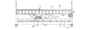
図1〜7に示すように、本発明に係る医療用ベッドは、ベッドフレーム100、支持板111、昇降用ユニット120、昇降部材130、水受け部190及び角度調節手段140を含んで構成される。
As shown in FIGS. 1-7, the medical bed which concerns on this invention is comprised including the
前記ベッドフレーム100に設置された脚101には、ベッドフレーム100の移動を容易にするために移動ローラー102がさらに設置される。また、患者の細胞の生理作用を活発にし、人体の内部に熱エネルギーを発生させ、人体内の細胞の有害物質を放出して解毒する光電効果に優れ、かつ患者の健康を最適化できる黄土ベッドユニット110は、多数位置して患者の身体を支持する。
In order to facilitate movement of the
また、患者の身体を洗うとき、黄土ベッドユニット110が濡れることを防止するために、黄土ベッドユニット110には防水カバー112が被せられる。
Further, when the patient's body is washed, the
前記ベッドフレーム100の両側には、昇降用ユニットの作動時に黄土ベッドユニット110が上側に過度に上昇することを防止するために離脱防止部107がさらに形成される。
On both sides of the
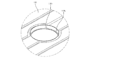
そして、前記黄土ベッドユニット110のうちベッドの中央部分、すなわち、患者のお尻が位置する黄土ベッドユニット110には、中央部分が一定の間隔だけ離隔して開放部110aが形成され、前記開放部110aには支え枠110bがさらに備えられる。そして、前記支え枠110bには開放部110aを開閉するための黄土ベッド兼用蓋220が挿入され、患者が用便をしようとするとき、前記黄土ベッド兼用蓋220を開放部110aから分離することによって、自ら動けない患者をトイレに連れて行かなくても、患者がその場で楽に用便をすることができる。
In the
併せて、ベッドフレーム100の内部空間には、レール部104がベッドフレーム100の長さ方向に設置される。
In addition, a
そして、下側の上下両方に車輪200が設置され、一側に水が排出される排出口201が形成され、底面がベッドフレーム100の長さ方向に傾いた水受け部190は、前記レール部104に位置し、ベッドフレーム100の内/外側に容易にスライディングされる。その結果、使用者は、前記水受け部190を必要に応じて楽に取り出し、水垢及び異物を除去することができる。
And the
また、前記水受け部190の底面が一定の角度だけ傾くことによって、患者の身体を洗うときに流入する水、患者の身体を洗った後で残存する汚染物及び排泄物などは、迅速に排出口201側に流れ、この排出口201を介して効率的にベッドフレーム100の外部に排出することができる。
In addition, since the bottom surface of the
これに加えて、前記排出口201に排出ホースを設置し、身体を洗った後で残存する汚染物及び排泄物などが下水道に流れるようにすることが望ましい。
In addition, it is desirable to install a discharge hose at the
そして、服を脱いだ患者の身体を覆うことによって患者のプライバシーを保護するとともに、水が外部に飛散することを防止するために、簡単に設置/解除可能な入浴用カーテン105がベッドフレーム100にさらに備えられる。
The
また、ベッドフレーム100に設置された支持バー(図示せず)には、患者の血液循環を促進し、床擦れ防止機能を高めることができる送風ファン106がさらに設置される。
In addition, a support bar (not shown) installed on the
また、前記ベッドフレーム100には、支持部231、垂直部232、作動レバー234、シャワー器235、貯蔵容器237及び噴射ホース238を含んで構成される洗浄水供給部材230がさらに設置され、このような洗浄水供給部材230は、水が供給される水道施設が設けられた場所と水道施設が設けられていない場所のいずれにおいても患者に容易にシャワーを浴びせるようにする。
The
まず、水が供給される水道施設が設けられた場所では、支持部231、垂直部232、作動レバー234及びシャワー器235が使用される。
First, in a place where a water supply facility to which water is supplied is provided, a
前記支持部231の下面に車輪231aが設置されることによって、洗浄水供給部材230の移動が容易になる。また、前記垂直部232は、支持部231の上面から上側に延長形成され、途中にはシャワー用品を置くための棚233が備えられ、このような支持部231は中空の四角棒形態から成る。
By installing the
また、前記作動レバー234は、前記垂直部232の上端に形成され、供給された水を冷・温水に調節するために使用される。また、前記シャワー器235には連結ホース236が備えられ、この連結ホース236が蛇口(図示せず)に設置されることによって、前記シャワー器235は、前記作動レバー234の上下作動によって冷・温水を噴射したり、冷・温水の噴射を中断する。
The operating
これと反対に、水が供給される水道施設が設けられていない場所では、貯蔵容器237及び噴射ホース238が使用される。
On the contrary, the
前記貯蔵容器237は前記垂直部232に設置され、その内部空間には一定水位の洗浄水が収容されており、前記噴射ホース238は、前記貯蔵容器237に設置されて洗浄水を噴射する。
The
また、前記噴射ホース238が前記貯蔵容器237の洗浄水を噴射できるように、前記貯蔵容器237にはポンプ239がさらに備えられ、ポンピング作用を通して貯蔵容器237内部の洗浄水が噴射ホース238を介して容易に噴射されるようにすることが望ましい。
Further, the
前記支持板111は、黄土ベッドユニット110に設置されて黄土ベッドユニット110を支持し、黄土ベッドユニット110の昇降を案内する。
The
前記昇降用ユニット120は、支持板111に設置され、この支持板111を支持するヘッド部121と、前記ヘッド部121の下側に延長形成され、前記黄土ベッドユニット110の昇降を案内する本体部122と、前記本体部122の下側に延長形成され、弾性スプリング133の上側に定着される定着部124とを含んで構成され、底面から一定の高さを維持した状態でベッドフレーム100に設置される。
The elevating
前記昇降部材130は、患者が横たわっている状態を維持しながら患者の身体の後部と黄土ベッドユニット110との間に空間を形成することによって、患者の身体の後部に血液と空気を疎通させ、周期的に患者の身体の後部に空気が流れるようにし、長期間の間ベッド生活をしてきた患者に発生する床擦れなどの疾患を未然に防止するために提供されるものである。また、前記昇降部材130は、ベッドフレーム100の内部空間に形成された固定台103にねじ及びボルトによって結合され、昇降部材130の内部空間には昇降用ユニット120の一部が挿入されるようにするための挿入ホール132が形成され、その内部に配置された弾性スプリング133が前記定着部124を支持し、上側には油空圧が注入又は排出される流入口131が形成され、前記昇降用ユニット120を上下方向に垂直に移動させる。
The elevating
前記弾性スプリング133は、普段は昇降用ユニット120を支えているが、流入口131を介して昇降部材130の内部に油空圧が注入されると、昇降用ユニット120の下降とともに圧縮されながら復元力を有するようになり、昇降部材130の外部に油空圧が排出されると、復元力によって昇降用ユニット120を元の位置に復元させる。
The
また、前記昇降部材130には、電子バルブ150、ポンプ170、コントローラ部134及びタイマー135がさらに設置される。
The elevating
前記電子バルブ150は、コントローラ部134によってオープン/クローズされなながら昇降部材130の内部に油空圧が流入することを制御し、前記ポンプ170は、油空圧器に貯蔵された油空圧を前記昇降部材130の内部に流入させる。
The
また、前記タイマー135は、使用者が予め定めておいた入力時間に合わせて多数の昇降部材130に油空圧を交互に流入させ、昇降用ユニット120を交互に昇降させるために提供されるもので、使用者が定めておいた時間に合わせて制御信号をコントローラ部134に送信する。そして、前記コントローラ部134は、タイマー135から制御信号を受け、多数設置された電子バルブ150のオープン/クローズ及びポンプ170の作動を制御し、ベッドフレーム100に設置された多数の昇降部材130の内部に油空圧を交互に流入させる。
In addition, the
前記昇降用ユニット120の駆動方式は、図3に示すように、ポンプ170を作動させ、油空圧器180に貯蔵された油空圧を昇降部材130の上側に形成された流入口131を介して昇降部材130の内部に流入させると、この油空圧によって昇降用ユニット120の加圧部123が弾性スプリング133を圧縮しながら下降すると同時に、結合された黄土ベッドユニット110と支持板111がヘッド部121と共に下降するようになる。
As shown in FIG. 3, the raising / lowering
そして、前記昇降用ユニット120の上昇は、昇降部材130の上側に形成された流入口131を塞いでいる電子バルブ150を開放し、昇降部材130の外部に油空圧を排出した後、電子バルブをクローズすると、昇降部材130の内部空間には圧力が消えるようになり、昇降用ユニット120の下降とともに圧縮されながら復元力を有するようになった弾性スプリング133は、この復元力によって昇降用ユニット120を元の位置に復元させる。
The raising / lowering
前記角度調節手段140は、図4に示すように、ベッドフレーム100に設置され、ピストン棒142が備えられたシリンダー141と、一側は第1のヒンジ部144によって前記ピストン棒142と結合され、このピストン棒142に近接した位置にベアリング148が設置され、他側は第2のヒンジ部145によってベッドフレーム100に結合されるリンク部143と、前記ベアリング148が位置し、このベアリング148がスライディングされる内部空間が形成され、リンク部143を支持する支持フレーム147と、前記ベッドフレーム100の一面に設置され、ベッドフレーム100の角運動を行う第3のヒンジ部146とを含んで構成される。
As shown in FIG. 4, the
前記角度調節手段140の作動は、図5に示すように、シリンダー141に油空圧が注入されると、ピストン棒142が水平方向に前進するようになり、第1のヒンジ部144によってピストン棒142と結合されたリンク部143が垂直方向に上昇しながら、ベッドフレーム100を垂直方向に移動させ、ベッドフレーム100が一定の角度を有するようにし、患者の上体を上側に移動させることができる。ここで、ベッドフレーム100は、第3のヒンジ部146によって角運動を行うことができる。
As shown in FIG. 5, when the hydraulic pressure is injected into the
そして、シリンダー141の内部の油空圧を外部に排出すると、ピストン棒142が元の位置に復帰することによって、ピストン棒142に結合されたリンク部143も元の位置に復帰するようになり、ベッドフレーム100が再び一定の水平状態を維持するようになる。
When the hydraulic pressure inside the
図中、未説明符号160は、油空圧が流れる通路管である。
In the figure, an
<実施例2> <Example 2>
図8は、本発明に係る医療用ベッドの分解斜視図で、図9は、本発明に係る医療用ベッドにおける開放部の拡大図で、図10は、本発明に係る医療用ベッドに便器が適用された状態を示す図で、図11及び図12は、本発明に係る医療用ベッドにおける角度調節手段の作動過程を示す図で、図13は、本発明に係る医療用ベッドにおいて昇降部材によって昇降用ユニットが作動する実施例を示す図で、図14は、本発明に係る医療用ベッドにおける洗浄水供給部材を示す図である。 FIG. 8 is an exploded perspective view of the medical bed according to the present invention, FIG. 9 is an enlarged view of an open portion of the medical bed according to the present invention, and FIG. 10 shows a toilet in the medical bed according to the present invention. FIG. 11 and FIG. 12 are views showing an operation process of the angle adjusting means in the medical bed according to the present invention, and FIG. 13 is a view showing the applied state by the elevating member in the medical bed according to the present invention. FIG. 14 is a view showing an embodiment in which the lifting unit is operated, and FIG. 14 is a view showing a cleaning water supply member in the medical bed according to the present invention.
図8〜14に示すように、本発明に係る医療用ベッドは、ベッドフレーム100、支持板111、昇降用ユニット120、昇降部材130、水受け部190及び角度調節手段140を含んで構成される。
As shown in FIGS. 8 to 14, the medical bed according to the present invention includes a
前記ベッドフレーム100に設置された脚101には、ベッドフレーム100の移動を容易にするために移動ローラー102がさらに設置される。また、患者の細胞の生理作用を活発にし、人体の内部に熱エネルギーを発生させ、人体内の細胞の有害物質を放出して解毒する光電効果に優れ、かつ患者の健康を最適化できる黄土ベッドユニット110は、多数位置して患者の身体を支持する。
In order to facilitate movement of the
また、患者の身体を洗うとき、黄土ベッドユニット110が濡れることを防止するために、黄土ベッドユニット110に防水カバー112が被せられる。
In addition, when the patient's body is washed, the
前記ベッドフレーム100の両側には、昇降用ユニット120の作動時に黄土ベッドユニット110が上側に過度に上昇することを防止するために離脱防止部107がさらに形成される。
On both sides of the
そして、前記黄土ベッドユニット110のうちベッドの中央部分、すなわち、患者のお尻が位置する黄土ベッドユニット110には、中央部分が一定間隔だけ離隔して開放部110aが形成され、前記開放部110aには支え枠110bがさらに備えられる。そして、前記支え枠110bには、開放部110aを開閉するための黄土ベッド兼用蓋220が挿入され、患者が用便をしようとする場合、前記黄土ベッド兼用蓋220を開放部110aから分離することによって、自ら動けない患者をトイレに連れて行かずにも、患者がその場で楽に用便をすることができる。
In the
併せて、ベッドフレーム100の内部空間には、レール部104がベッドフレーム100の長さ方向に設置される。
In addition, a
そして、下側の上下両方に車輪200が設置され、一側に水が排出される排出口201が形成され、底面がベッドフレーム100の長さ方向に傾いた水受け部190は、前記レール部104に位置し、ベッドフレーム100の内/外側に容易にスライディングされる。その結果、使用者は、前記水受け部190を必要に応じて楽に取り出し、水垢及び異物を除去することができる。
And the
また、前記水受け部190の底面が一定の角度だけ傾くことによって、患者の身体を洗うときに流入する水、患者の身体を洗った後で残存する汚染物及び排泄物などは、迅速に排出口201側に流れ、この排出口201を介して効率的にベッドフレーム100の外部に排出することができる。
In addition, since the bottom surface of the
これに加えて、前記排出口201に排出ホースを設置し、身体を洗った後で残存する汚染物及び排泄物などが下水道に流れるようにすることが望ましい。
In addition, it is desirable to install a discharge hose at the
そして、服を脱いだ患者の身体を覆うことによって患者のプライバシーを保護するとともに、水が外部に飛散することを防止するために、簡単に設置/解除可能な入浴用カーテン105がベッドフレーム100にさらに備えられる。
The
また、ベッドフレーム100に設置された支持バー(図示せず)には、患者の血液循環を促進し、床擦れ防止機能を高めることができる送風ファン106がさらに設置される。
In addition, a support bar (not shown) installed on the
また、前記ベッドフレーム100には、支持部231、垂直部232、作動レバー234、シャワー器235、貯蔵容器237及び噴射ホース238を含んで構成される洗浄水供給部材230がさらに設置され、このような洗浄水供給部材230は、水が供給される水道施設が設けられた場所と水道施設が設けられていない場所のいずれにおいても患者に容易にシャワーを浴びせるようにする。
The
まず、水が供給される水道施設が設けられた場所では、支持部231、垂直部232、作動レバー234及びシャワー器235が使用される。
First, in a place where a water supply facility to which water is supplied is provided, a
前記支持部231の下面に車輪231aが設置されることによって、洗浄水供給部材230の移動が容易になる。また、前記垂直部232は、支持部231の上面から上側に延長形成され、途中にはシャワー用品を置くための棚233が備えられ、このような支持部231は中空の四角棒形態から成る。
By installing the
また、前記作動レバー234は、前記垂直部232の上端に形成され、供給された水を冷・温水に調節するために使用される。また、前記シャワー器235には連結ホース238が備えられ、この連結ホース236が蛇口(図示せず)に設置されることによって、前記シャワー器235は、前記作動レバー234の上下作動によって冷・温水を噴射したり、冷温水の噴射を中断する。
The operating
これと反対に、水が供給される水道施設が設けられていない場所では、貯蔵容器237及び噴射ホース238が使用される。
On the contrary, the
前記貯蔵容器237は、連結部材を通して前記垂直部232に設置され、その内部空間には一定水位の洗浄水が収容されており、前記噴射ホース238は、前記貯蔵容器237に設置されて洗浄水を噴射する。
The
また、前記噴射ホース238が前記貯蔵容器237の洗浄水を噴射できるように、前記貯蔵容器237にはポンプ239がさらに備えられ、ポンピング作用を通して貯蔵容器237内部の洗浄水が噴射ホース238を介して容易に噴射されるようにすることが望ましい。
Further, the
前記支持板111は、黄土ベッドユニット110に設置されて黄土ベッドユニット110を支持し、黄土ベッドユニット110の昇降を案内する。
The
前記昇降用ユニット120は、支持板111に設置され、この支持板111を支持するヘッド部121と、前記ヘッド部121の下側に延長形成され、前記黄土ベッドユニット110の昇降を案内する本体部122と、前記本体部122の下側に延長形成され、昇降部材130の内部空間に圧力を加える加圧部123とを含んで構成され、底面から一定の高さを維持した状態でベッドフレーム100に設置される。
The elevating
前記昇降部材130は、患者が横たわっている状態を維持しながら患者の身体の後部と黄土ベッドユニット110との間に空間を形成することによって、患者の身体の後部に血液と空気を疎通させ、周期的に患者の身体の後部に空気が流れるようにし、長期間の間ベッド生活をしてきた患者に発生する床擦れなどの疾患を未然に防止するために提供されるものである。また、前記昇降部材130は、ベッドフレーム100の内部空間に形成された固定台103にねじ及びボルトによって結合され、昇降部材130の内部空間には昇降用ユニット120の一部が挿入されるようにするための挿入ホール132が形成され、上側と下側に油空圧が注入又は排出される流入口131が形成され、前記昇降用ユニット120を上下方向に垂直に移動させる。
The elevating
また、前記昇降部材130には、電子バルブ150、151、ポンプ170、コントローラ部134及びタイマー135がさらに設置される。
The elevating
前記電子バルブ150、151は、コントローラ部134によってオープン/クローズされながら昇降部材130の内部に油空圧が流入することを制御し、前記ポンプ170は、流空気圧器180に貯蔵された油空圧を前記昇降部材130の内部に流入させる。
The
また、前記タイマー135は、使用者が予め定めておいた入力時間に合わせて多数の昇降部材130に油空圧を交互に流入させ、昇降用ユニット120を交互に昇降させるために提供されるもので、使用者が定めおいた時間に合わせて制御信号をコントローラ部134に送信する。また、前記コントローラ部134は、タイマー135から制御信号を受け、多数設置された電子バルブ150、151のオープン/クローズ及びポンプ170の作動を制御し、ベッドフレーム100に設置された多数の昇降部材130の内部に油空圧を交互に流入させる。
In addition, the
前記昇降用ユニット120の駆動方式は、図7に示すように、昇降部材130の下側に形成された流入口131’を介して昇降部材130の内部に油空圧が流入しないように電子バルブ151’を閉鎖し、流入管160を介して昇降部材130の内部空間に油空圧が流入するように電子バルブ151を開放した後、ポンプ170を作動させ、油空圧器180に貯蔵された油空圧を昇降部材130の内部空間に流入させると、この油空圧によって昇降用ユニット120が下降するとともに、結合されている黄土ベッドユニット110と支持板111がヘッド部121と共に下降するようになる。
As shown in FIG. 7, the elevating
そして、前記昇降用ユニット120の上昇は、昇降部材130の上側に形成された流入口131を塞いでいる電子バルブ151を開放し、昇降部材130の外部に油空圧を排出する。その後、昇降部材130の上側に形成された流入口131を介して昇降部材130の内部に油空圧が流入しないように、電子バルブ151を閉鎖する。
Then, the raising / lowering of the lifting / lowering
そして、流入管160を介して昇降部材130の内部空間に油空圧が流入するように電子バルブ151’を開放し、ポンプ170を作動させ、昇降部材130の内部空間に油空圧を流入させると、この油空圧によって昇降用ユニット120が上昇するとともに、結合されている黄土ベッドユニット110と支持板111がヘッド部121と共に上昇しながら元の位置に復元される。
Then, the electronic valve 151 ′ is opened so that the hydraulic pressure flows into the internal space of the elevating
前記角度調節手段の構成と作動は、実施例1に説明した通りであるので、それについての具体的な説明は省略する。 Since the configuration and operation of the angle adjusting means are as described in the first embodiment, a detailed description thereof will be omitted.
Claims (20)
黄土含有ベッドユニット(110)に設置され、黄土含有ベッドユニット(110)を支持する支持板(111)と;
支持板(111)に設置されるヘッド部(121)と、ヘッド部(121)の下側に延長形成され、黄土含有ベッドユニット(110)の昇降を案内する本体部(122)と、その本体部の下側に延長形成され、弾性スプリング(133)の上側に定着され、昇降部材(130)の内部空間に圧力を加える定着部(124)と、から成り、底面から一定の高さを維持した状態で設置された昇降用ユニット(120)と;
固定台(103)に設置され、内部に弾性スプリング(133)が配置され、上側に油空圧が注入及び排出される流入口(131)が形成され、昇降用ユニット(120)を上下方向に垂直に移動させる昇降部材(130)と;
ベッドフレーム(100)の内部空間に位置し、下側の上下両方に車輪(200)が設置され、底面が一定の傾斜面を有する水受け部(190)と;
ベッドフレーム(100)に設置され、ベッドフレーム(100)の角運動を行う角度調節手段(140)と;を備える
ことを特徴とする医療用ベッド。The internal space is formed, the legs (101) on which the moving rollers (102) are formed are installed, a large number of loess- containing bed units (110) are installed, and the ocher- containing bed units (110) are separated from both sides. A bed frame (100) in which a separation prevention part (107) for preventing is formed;
Installed in loess containing bed unit (110), a support plate for supporting the loess containing bed units (110) and (111);
A head portion (121) installed on the support plate (111), a main body portion (122) that is extended below the head portion (121) and guides the raising and lowering of the loess- containing bed unit (110), and its main body And a fixing portion (124) that is fixed to the upper side of the elastic spring (133) and applies pressure to the internal space of the elevating member (130), and maintains a constant height from the bottom surface. A lifting and lowering unit (120) installed in a closed state;
Installed on the fixed base (103), an elastic spring (133) is arranged inside, an inlet (131) is formed on the upper side for injecting and discharging hydraulic pressure, and the lifting unit (120) is moved vertically Elevating member (130) for vertical movement;
A water receiving part (190) which is located in the internal space of the bed frame (100), has wheels (200) installed on both the upper and lower sides thereof, and has a bottom surface having a constant inclined surface;
An angle adjustment means (140) that is installed on the bed frame (100) and performs an angular motion of the bed frame (100).
請求項1に記載の医療用ベッド。The medical bed according to claim 1, wherein a rail portion (104) for guiding sliding of a wheel (201) formed in the water receiving portion (200) is installed in an internal space of the bed frame (100).
請求項1に記載の医療用ベッド。The medical bed according to claim 1, wherein the bed frame (100) includes a bathing curtain (105).
請求項1に記載の医療用ベッド。The medical bed according to claim 1, wherein the bed frame (100) is provided with a blower fan (106) for promoting blood circulation of the patient.
請求項1に記載の医療用ベッド。The central portion of the loess containing bed unit located in the central portion of the bed frame (100) of ocher-containing bed units (110) (110), opening the supporting frame (110b) is provided (110a) is formed, The medical bed according to claim 1, wherein the open part (110a) is closed by inserting the loess- containing bed / cap (220) into the open part (110a).
請求項1に記載の医療用ベッド。On the bed frame (100), a support part (231) having wheels (231a) provided on the lower surface, and a vertical part extending upward from the upper surface of the support part (231) and provided with a shelf (233) in the middle. (232) and an operating lever (234) for adjusting cold / hot water and a connecting hose (236) for receiving water from the outside are installed at the upper end of the vertical portion (232) of the vertical portion (232). A shower unit (235) which is accommodated inside and protrudes to the outside of the operating lever (234) and injects water supplied from the connection hose (236), and a bolt and a nut are installed in the vertical part (232). A cleaning water supply member (230) comprising a storage container (237) in which cleaning water of a constant water level is accommodated in the internal space, and an injection hose (238) for injecting the cleaning water of the storage container (237) is provided. The medical bed according to claim 1 which is.
請求項1に記載の医療用ベッド。An electronic valve (150) for controlling the hydraulic / pneumatic pressure flowing into the elevating / lowering member (130) and the hydraulic / pneumatic pressure stored in the hydraulic / pneumatic device are caused to flow into the elevating / lowering member (130). A pump (170), a controller unit (134) for controlling the opening / closing of the electronic valve (150) and the operation of the pump, and a timer (135) for transmitting a control signal to the controller unit (134) in accordance with a certain period. The medical bed according to claim 1, wherein and are installed.
請求項1に記載の医療用ベッド。The medical bed according to claim 1, wherein the ocher- containing bed unit (110) is covered with a waterproof cover (112).
請求項1に記載の医療用ベッド。The medical bed according to claim 1, wherein a discharge port (201) through which water is discharged is formed on one side of the water receiving portion (190).
請求項1に記載の医療用ベッド。An angle adjusting means (140) is installed on the bed frame (100) and is provided with a cylinder (141) provided with a piston rod (142), and one side is connected to the piston rod (142) by a first hinge part (144). The bearing (148) is installed at a position close to the piston rod (142) and the other side is coupled to the bed frame (100) by the second hinge part (145). The bearing (148) is located, an internal space is formed in which the bearing (148) is slid, and the support frame (147) that supports the link part (143) is installed on one surface of the bed frame (100). The medical bed according to claim 1, further comprising a third hinge portion (146) for performing angular motion of the frame (100).
黄土含有ベッドユニット(110)に設置され、黄土含有ベッドユニット(110)を支持する支持板(111)と;
支持板(111)に設置されるヘッド部(121)と、ヘッド部(121)の下側に延長形成され、黄土含有ベッドユニット(110)の昇降を案内する本体部(122)と、本体部(122)の下側に延長形成され、昇降部材(130)の内部空間に圧力を加える加圧部(123)と、から成り、底面から一定の高さを維持した状態で設置される昇降用ユニット(120)と;
固定台(103)に設置され、上側と下側に油空圧が注入及び排出される流入口(131、131')が形成され、昇降用ユニット(120)を上下方向に垂直に移動させる昇降部材(130)と;
ベッドフレーム(100)の内部空間に位置し、下側の上下両方に車輪(200)が設置され、底面が一定の傾斜面を有する水受け部(190)と;
ベッドフレーム(100)に設置され、ベッドフレーム(100)の角運動を行う角度調節手段(140)と;を備える
ことを特徴とする医療用ベッド。The internal space is formed, the legs (101) on which the moving rollers (102) are formed are installed, a large number of loess- containing bed units (110) are installed, and the ocher- containing bed units (110) are separated from both sides. A bed frame (100) in which a separation prevention part (107) for preventing is formed;
Installed in loess containing bed unit (110), a support plate for supporting the loess containing bed units (110) and (111);
A head part (121) installed on the support plate (111), a main body part (122) extended below the head part (121) and guiding the raising and lowering of the loess- containing bed unit (110), and a main body part (122) is formed to extend below the pressurizing part (123) that applies pressure to the internal space of the elevating member (130), and is installed in a state of maintaining a certain height from the bottom surface A unit (120);
Elevating and lowering which is installed on the fixed base (103) and has inlets (131, 131 ') for injecting and discharging hydraulic air pressure on the upper and lower sides to vertically move the elevating unit (120) vertically A member (130);
A water receiving part (190) which is located in the internal space of the bed frame (100), has wheels (200) installed on both the upper and lower sides thereof, and has a bottom surface having a constant inclined surface;
An angle adjustment means (140) that is installed on the bed frame (100) and performs an angular motion of the bed frame (100).
請求項11に記載の医療用ベッド。The medical bed according to claim 11, wherein a rail part (104) for guiding sliding of a wheel (201) formed in the water receiving part (200) is installed in an internal space of the bed frame (100).
請求項11に記載の医療用ベッド。The medical bed according to claim 11, wherein the bed frame (100) includes a bathing curtain (105).
請求項11に記載の医療用ベッド。The medical bed according to claim 11, wherein the bed frame (100) is provided with a blower fan (106) for promoting blood circulation of the patient.
請求項11に記載の医療用ベッド。The central portion of the loess containing bed unit located in the central portion of the bed frame (100) of ocher-containing bed units (110) (110), opening the supporting frame (110b) is provided (110a) is further formed The medical bed according to claim 11, wherein the open part (110a) is closed by inserting the loess- containing bed combined lid (220) into the open part (110a).
請求項11に記載の医療用ベッド。On the bed frame (100), a support part (231) having wheels (231a) provided on the lower surface, and a vertical part extending upward from the upper surface of the support part (231) and provided with a shelf (233) in the middle. (232) and an operating lever (234) for adjusting cold / hot water and a connecting hose (236) for receiving water from the outside are installed at the upper end of the vertical portion (232) of the vertical portion (232). A shower unit (235) which is accommodated inside and protrudes to the outside of the operating lever (234) and injects water supplied from the connection hose (236), and a bolt and a nut are installed in the vertical part (232). A cleaning water supply member (230) comprising a storage container (237) in which cleaning water of a constant water level is accommodated in the internal space, and an injection hose (238) for injecting the cleaning water of the storage container (237). The medical bed according to claim 11 provided.
請求項11に記載の医療用ベッド。An electronic valve (150, 151) for controlling the hydraulic / pneumatic pressure flowing into the elevating / lowering member (130) into the elevating / lowering member (130), and the oil / pneumatic pressure stored in the hydraulic / pneumatic pressure device inside the elevating / lowering member. A pump (170) to be introduced, a controller unit (134) for controlling the opening / closing of the electronic valve (150) and the operation of the pump, and a timer (for transmitting a control signal to the controller unit (134) in accordance with a certain period) 135) and the medical bed according to claim 11.
請求項11に記載の医療用ベッド。The medical bed according to claim 11, wherein the ocher- containing bed unit (110) is covered with a waterproof cover (112).
請求項11に記載の医療用ベッド。The medical bed according to claim 11, wherein a discharge port (201) through which water is discharged is formed on one side of the water receiving portion (190).
請求項11に記載の医療用ベッド。An angle adjusting means (140) is installed on the bed frame (100) and is provided with a cylinder (141) provided with a piston rod (142), and one side is connected to the piston rod (142) by a first hinge part (144). The bearing (148) is installed at a position close to the piston rod (142) and the other side is coupled to the bed frame (100) by the second hinge part (145). The bearing (148) is located, an internal space is formed in which the bearing (148) is slid, and the support frame (147) that supports the link part (143) is installed on one surface of the bed frame (100). The medical bed according to claim 11, further comprising a third hinge portion (146) for performing angular motion of the frame (100).
Applications Claiming Priority (5)
| Application Number | Priority Date | Filing Date | Title |
|---|---|---|---|
| KR10-2008-0094997 | 2008-09-26 | ||
| KR20080094997 | 2008-09-26 | ||
| KR1020090069104A KR100947374B1 (en) | 2008-09-26 | 2009-07-28 | A medical bed |
| KR10-2009-0069104 | 2009-07-28 | ||
| PCT/KR2009/005072 WO2010035968A2 (en) | 2008-09-26 | 2009-09-08 | Medical bed |
Publications (2)
| Publication Number | Publication Date |
|---|---|
| JP2012503520A JP2012503520A (en) | 2012-02-09 |
| JP5167414B2 true JP5167414B2 (en) | 2013-03-21 |
Family
ID=42183292
Family Applications (1)
| Application Number | Title | Priority Date | Filing Date |
|---|---|---|---|
| JP2011528921A Expired - Fee Related JP5167414B2 (en) | 2008-09-26 | 2009-09-08 | Medical bed |
Country Status (6)
| Country | Link |
|---|---|
| US (1) | US8424134B2 (en) |
| EP (1) | EP2338457A4 (en) |
| JP (1) | JP5167414B2 (en) |
| KR (1) | KR100947374B1 (en) |
| CN (1) | CN102164570B (en) |
| WO (1) | WO2010035968A2 (en) |
Families Citing this family (43)
| Publication number | Priority date | Publication date | Assignee | Title |
|---|---|---|---|---|
| KR100947374B1 (en) * | 2008-09-26 | 2010-03-15 | 주식회사 코스피 | A medical bed |
| KR101027814B1 (en) * | 2010-10-07 | 2011-04-07 | 백창현 | A deep sleep bed for home |
| CN103228183A (en) * | 2010-12-06 | 2013-07-31 | Jt拉布斯有限公司 | Adjustable contour mattress system |
| WO2013021237A1 (en) * | 2011-08-06 | 2013-02-14 | Vu Nguyen Long Uy | Multi-care bedding apparatus |
| CN104884021B (en) * | 2012-12-21 | 2017-09-22 | 川崎重工业株式会社 | Bed with special provision for nursing and its shape variation |
| CN104095719B (en) * | 2013-04-11 | 2018-01-23 | 吴土泉 | Care bed |
| CN104095721A (en) * | 2013-04-11 | 2014-10-15 | 吴土泉 | Automatic nursing bed |
| GB2520507B (en) * | 2013-11-21 | 2017-03-01 | Huntleigh Technology Ltd | Footswitch Assembly |
| CN103908388B (en) * | 2014-03-11 | 2016-03-09 | 宁波康麦隆医疗器械有限公司 | Sick bed can be extended |
| BR202014006121Y1 (en) * | 2014-03-14 | 2020-12-08 | Eduardo Antonio Cauduro | constructive disposition in a hospital bed equipped with a physiological decubitus system |
| CN103830059A (en) * | 2014-03-26 | 2014-06-04 | 吴小玲 | Multifunctional array type stand column bed |
| CN104055637B (en) * | 2014-06-13 | 2016-09-14 | 浙江工业大学 | medical sickbed |
| USD783332S1 (en) * | 2014-07-21 | 2017-04-11 | Eiken Inc. | Adjustable bed with bedpan |
| CN104173159B (en) * | 2014-09-02 | 2017-05-03 | 扬州大学 | Treatment couch specific to rehabilitation of bedridden patient |
| KR101636928B1 (en) * | 2014-11-04 | 2016-07-07 | 주식회사 씨엠아이 | Mattress Apparatus For Pressure Sore Prevention |
| CN105105946B (en) * | 2015-06-26 | 2017-07-04 | 宁波欧利吉医疗科技有限公司 | A kind of automatic rehabilitation medical bed for preventing and treating bedsore |
| KR101689123B1 (en) * | 2015-10-21 | 2016-12-23 | 김선갑 | Bed for hospital |
| US10639221B2 (en) * | 2016-02-24 | 2020-05-05 | Dreamwell, Ltd. | Adjustable foundation and mattress assembly |
| US10506884B2 (en) * | 2016-02-24 | 2019-12-17 | Dreamwell, Ltd. | Adjustable foundation |
| US10568434B2 (en) * | 2016-02-24 | 2020-02-25 | Dreamwell, Ltd. | Adjustable foundation |
| KR101761706B1 (en) * | 2016-05-02 | 2017-07-26 | (재)예수병원유지재단 | Patient bed with bedsore prevention |
| US10695243B2 (en) | 2016-07-01 | 2020-06-30 | Jifeng Zhang | Multi-function multi-configuration care bed for enhanced patient comfort and caregiver convenience |
| CN106420228A (en) * | 2016-08-31 | 2017-02-22 | 郭翠莲 | Movable bath bed |
| CN106264917A (en) * | 2016-08-31 | 2017-01-04 | 张连江 | A kind of medical treatment and nursing use water wash cycles sick bed |
| CN106377366B (en) * | 2016-09-06 | 2019-01-15 | 上海电机学院 | A kind of intelligent omnibearing nursing bed |
| US11116325B2 (en) * | 2017-03-24 | 2021-09-14 | Bedgear, Llc | Zero gravity bed |
| US10821042B1 (en) * | 2018-03-27 | 2020-11-03 | Beatrice Williams | Patient bed with mattress and integrated bed pan |
| CN109758317A (en) * | 2019-03-05 | 2019-05-17 | 南通市第一人民医院 | A kind of alternative expression supporting bed preventing pressure sore |
| CN109966083B (en) * | 2019-04-22 | 2020-12-29 | 李付荣 | Internal medicine nursing device |
| CN110787008A (en) * | 2019-10-15 | 2020-02-14 | 湖南粤科汇智能科技有限公司 | Cleaning mechanism |
| KR102311865B1 (en) | 2019-11-18 | 2021-10-13 | 주식회사 알파로보틱스 | a medical bed |
| CN111202649B (en) * | 2020-01-14 | 2021-09-21 | 山东大学 | Orthopedic posture support adjusting device and method |
| CN111281699B (en) * | 2020-03-26 | 2021-06-11 | 广州恒琢科技有限公司 | Intelligent nursing bed |
| KR102517558B1 (en) * | 2020-06-30 | 2023-04-04 | 고영지 | Bed robot apparatus |
| CN114053051A (en) * | 2020-08-07 | 2022-02-18 | 鹤壁市人民医院 | Department of neurology nurses bed |
| KR20220070688A (en) | 2020-11-23 | 2022-05-31 | 주식회사 알파로보틱스 | Bed robot with pressure ulcer prevention |
| KR102544427B1 (en) * | 2020-11-27 | 2023-06-20 | (주)옵토닉스 | Wheelchair with limited tilting angle and Bed including detachable Wheelchair |
| CN113244065B (en) * | 2021-04-12 | 2022-05-24 | 重庆电子工程职业学院 | Artificial intelligence monitoring device |
| KR102635997B1 (en) | 2021-11-02 | 2024-02-13 | 주식회사 알파로보틱스 | Bed robot for preventing bedsores |
| CN114392528B (en) * | 2022-01-05 | 2022-11-15 | 郑州市骨科医院 | Rehabilitation training device for spinal surgery |
| USD1015004S1 (en) | 2022-03-20 | 2024-02-20 | Yajun Hu | Medical bed |
| USD1012764S1 (en) | 2022-03-30 | 2024-01-30 | Yajun Hu | Medical bed |
| CN116077290B (en) * | 2023-03-24 | 2023-11-17 | 南方医科大学第三附属医院(广东省骨科研究院) | Sickbed for ICU |
Family Cites Families (28)
| Publication number | Priority date | Publication date | Assignee | Title |
|---|---|---|---|---|
| US818821A (en) * | 1905-06-24 | 1906-04-24 | William C Feely | Commode. |
| US3757355A (en) * | 1971-09-09 | 1973-09-11 | R Allen | Portable body waste collecting system |
| DE3728408A1 (en) * | 1987-08-26 | 1989-03-09 | Oswald Kurt | BED |
| IT1227726B (en) * | 1988-12-23 | 1991-05-06 | Di Blasi Rosario | BED WITH SUPPORTING PLAN CONFORMED AT LEAST IN PART ON THE KEYBOARD |
| US5054136A (en) * | 1989-10-20 | 1991-10-08 | Jitsuo Inagaki | Bed with a bath-tub |
| DE4024646C1 (en) * | 1990-08-03 | 1992-02-27 | Rolf 3320 Salzgitter De Wesemann | |
| DE69008726T2 (en) * | 1990-10-16 | 1994-10-27 | Complete Investments Ltd | Support device for the slats of a slatted frame. |
| JP2991777B2 (en) * | 1990-12-21 | 1999-12-20 | 福山 孝喜 | Bed |
| JPH0515555A (en) * | 1991-02-19 | 1993-01-26 | Daisan Sekkei Kogyo Kk | Medical bed |
| JPH078523A (en) * | 1993-06-22 | 1995-01-13 | Katsuyoshi Omoto | Bed with bedsore preventing device |
| JP3442863B2 (en) * | 1994-06-10 | 2003-09-02 | 隆 松浦 | Patient bed with release frame and moving device for release frame |
| KR0168326B1 (en) * | 1994-09-01 | 1999-01-15 | 스미요 가나이 | Bed system with excretion collecting means |
| JP2936385B2 (en) * | 1995-04-21 | 1999-08-23 | 種重 田尻 | Bed surface deformable bed |
| JP3097029B2 (en) * | 1996-10-09 | 2000-10-10 | 多摩重起建設株式会社 | Nursing bed with flush toilet |
| JP2000166991A (en) * | 1998-11-30 | 2000-06-20 | Polymer Kasei Kk | Bed sore preventing bed |
| DE10000831C1 (en) * | 2000-01-12 | 2001-07-05 | Uta Zenczykowski | Bed with three-dimensionally movable mattress has frame with feet on which mattress is accommodated in non-sprung but pliable manner |
| KR20000058591A (en) * | 2000-06-17 | 2000-10-05 | 홍길영 | A bed for patient |
| US6708353B2 (en) * | 2002-01-04 | 2004-03-23 | Wan-Seok Han | Protective apparatus for human backbones |
| KR20040011807A (en) * | 2002-07-30 | 2004-02-11 | 이윤상 | a patient bed |
| JP3707555B2 (en) * | 2002-10-24 | 2005-10-19 | パラマウントベッド株式会社 | Electric bed, its control method and control device |
| JP3977758B2 (en) * | 2003-02-14 | 2007-09-19 | 清 加藤 | Bedsore prevention bed |
| KR200356207Y1 (en) * | 2004-04-16 | 2004-07-14 | 조무현 | Mattress having human friendly materials and bed with the mattress |
| KR20060030556A (en) * | 2004-10-06 | 2006-04-11 | 장재이 | Patient bedstead |
| JP4057006B2 (en) * | 2004-10-20 | 2008-03-05 | 清 加藤 | Floor rubbing prevention device |
| KR100732559B1 (en) | 2005-07-11 | 2007-06-27 | 유도로보틱스(주) | Bed for preventing bedsore |
| KR200401864Y1 (en) | 2005-08-17 | 2005-11-22 | 주식회사 해피베드 | Bed for bathing patients |
| WO2008093527A1 (en) * | 2007-01-31 | 2008-08-07 | Takayuki Ishida | Nursing bed |
| KR100947374B1 (en) * | 2008-09-26 | 2010-03-15 | 주식회사 코스피 | A medical bed |
-
2009
- 2009-07-28 KR KR1020090069104A patent/KR100947374B1/en not_active IP Right Cessation
- 2009-09-08 US US12/998,064 patent/US8424134B2/en not_active Expired - Fee Related
- 2009-09-08 EP EP09816361.1A patent/EP2338457A4/en not_active Withdrawn
- 2009-09-08 JP JP2011528921A patent/JP5167414B2/en not_active Expired - Fee Related
- 2009-09-08 WO PCT/KR2009/005072 patent/WO2010035968A2/en active Application Filing
- 2009-09-08 CN CN2009801377106A patent/CN102164570B/en not_active Expired - Fee Related
Also Published As
| Publication number | Publication date |
|---|---|
| CN102164570B (en) | 2013-04-17 |
| EP2338457A4 (en) | 2014-11-05 |
| WO2010035968A2 (en) | 2010-04-01 |
| KR100947374B1 (en) | 2010-03-15 |
| WO2010035968A3 (en) | 2010-07-01 |
| JP2012503520A (en) | 2012-02-09 |
| EP2338457A2 (en) | 2011-06-29 |
| US8424134B2 (en) | 2013-04-23 |
| US20110162143A1 (en) | 2011-07-07 |
| CN102164570A (en) | 2011-08-24 |
Similar Documents
| Publication | Publication Date | Title |
|---|---|---|
| JP5167414B2 (en) | Medical bed | |
| EP1895883B1 (en) | Bathing system | |
| US4821348A (en) | Convertable bed and bathroom combination | |
| JP6215396B2 (en) | Nursing bed | |
| JP2008514243A (en) | Home care system | |
| CN101237803A (en) | Bathing system and related method | |
| RU2483701C2 (en) | Sanitary-hygienic complex for bed-patient care (versions) | |
| WO1998019020A1 (en) | Water closet and nursing bed device with same | |
| CN111494117B (en) | Multifunctional intelligent nursing bed and installation method thereof | |
| CN111494119B (en) | Nursing bed with closestool and bathtub and installation method thereof | |
| CN210205164U (en) | Multifunctional nursing bed | |
| CN113018036A (en) | Hammock subassembly and have nursing bed of this hammock subassembly | |
| CN205947966U (en) | Medical horizontal stool pot of separating | |
| KR200313187Y1 (en) | A Bed for Patient | |
| JP2001340398A (en) | Bed | |
| JP3150311B2 (en) | Bathing equipment | |
| CN1088080A (en) | Multi-functional intelligent hospital bed with bedpan | |
| KR102606870B1 (en) | Height adjustable defecation patient bed | |
| JPH0966076A (en) | Bed to be bathtub, toilet attachable and detachable to/ from the bed, bed using the toilet, bath and toilet system, mat for preventing bedsore and flush toilet | |
| JPH08224285A (en) | Bed also used as bathtub, toilet loadable/unloadable on the same and bed, bath and toilet system using the same | |
| KR20110008501A (en) | Baby cleaning machine of non electric power | |
| JPH0910126A (en) | Nursing bathroom | |
| JPH0337423B2 (en) | ||
| KR20040072169A (en) | A Bed for Patient | |
| JP2005224412A (en) | Body washing and drying apparatus |
Legal Events
| Date | Code | Title | Description |
|---|---|---|---|
| A131 | Notification of reasons for refusal |
Free format text: JAPANESE INTERMEDIATE CODE: A131 Effective date: 20120828 |
|
| A521 | Written amendment |
Free format text: JAPANESE INTERMEDIATE CODE: A523 Effective date: 20121115 |
|
| TRDD | Decision of grant or rejection written | ||
| A01 | Written decision to grant a patent or to grant a registration (utility model) |
Free format text: JAPANESE INTERMEDIATE CODE: A01 Effective date: 20121211 |
|
| A61 | First payment of annual fees (during grant procedure) |
Free format text: JAPANESE INTERMEDIATE CODE: A61 Effective date: 20121221 |
|
| FPAY | Renewal fee payment (event date is renewal date of database) |
Free format text: PAYMENT UNTIL: 20151228 Year of fee payment: 3 |
|
| R150 | Certificate of patent or registration of utility model |
Free format text: JAPANESE INTERMEDIATE CODE: R150 |
|
| LAPS | Cancellation because of no payment of annual fees |