JP3690210B2 - Portable shower device - Google Patents
Portable shower device Download PDFInfo
- Publication number
- JP3690210B2 JP3690210B2 JP30208199A JP30208199A JP3690210B2 JP 3690210 B2 JP3690210 B2 JP 3690210B2 JP 30208199 A JP30208199 A JP 30208199A JP 30208199 A JP30208199 A JP 30208199A JP 3690210 B2 JP3690210 B2 JP 3690210B2
- Authority
- JP
- Japan
- Prior art keywords
- waterproof pan
- shower
- lid
- bather
- shower device
- Prior art date
- Legal status (The legal status is an assumption and is not a legal conclusion. Google has not performed a legal analysis and makes no representation as to the accuracy of the status listed.)
- Expired - Fee Related
Links
Images


Landscapes
- Bathtubs, Showers, And Their Attachments (AREA)
- Body Washing Hand Wipes And Brushes (AREA)
- Devices For Medical Bathing And Washing (AREA)
Description
【0001】
【発明の属する技術分野】
本発明は携帯用シャワー装置に係り、更に詳しくは、コンパクトに折り畳むことができ、不使用時の収納や移動に便利な携帯用シャワー装置に関する。
【0002】
【従来の技術】
近時においては、身体障害者や寝たきりの高齢者等の介護対象者を入浴させる作業の軽減を図るために、例えば、特開平8−154858号公報や特開平10−192357号公報に提案されるように、移動可能な種々の介護用シャワー装置が出現するに至っている。特開平8−154858号公報のシャワー装置は、入浴者の身体を当該入浴者を運搬してきた車椅子ごと収容可能になっており、装置内部に収容された身体に向かって湯水を噴射することで入浴者の洗体を可能とするものである。また、特開平10−192357号公報のシャワー装置は、入浴者が横たわることができる載置台と、蛇腹状の浴槽シートを有する浴槽本体とからなっており、当該入浴者を載置台に横たわらせた後、入浴者に浴槽シートを被せてその内部に温水を供給することにより入浴者の洗体を可能とするものである。
【0003】
【発明が解決しようとする課題】
一般的に、介護用シャワー装置は、その使用時において、介護対象者のシャワー装置への運搬作業を軽減するため、介護対象者の寝室等に隣接して設置可能となるものが要請される一方、不使用時においては、寝室等のデッドスペースの軽減のため、所定の収納場所に移動可能となるものが要請される。しかしながら、前記各シャワー装置にあっては、その内部に入浴者が位置可能な入浴空間が形成されることから、必然的に入浴者より大きなサイズになるとともに、不使用時にコンパクトに折り畳むことができないため、介護対象者の寝室等に隣接して設置できても、収納や移動が困難になるという不都合がある。すなわち、前記各シャワー装置は、不使用時においても、なお大きなサイズであることから、不使用時に寝室の隅や押入等に収納することができずに、寝室から離れた別異の収納部屋等に移動しなければならない。また、シャワー装置の移動に際しては、その大きなサイズのため、扉の間口や床面の段差を通過させることが困難になる。従って、前記各シャワー装置にあっては、その移動作業に多大な労力を要し、これが、介護作業の負担を増大させる要因ともなる。更に、シャワー装置を車で運搬することが困難となるため、介護対象者宅に戸別にシャワー装置を設置しなければならず、装置の効率的な利用を図ることができない。
【0004】
【発明の目的】
本発明は、このような不都合に着目して案出されたものであり、その目的は、不使用時における収納に要するスペースの狭小化を実現することができるとともに、任意の場所への移動を容易に行うことができる携帯用シャワー装置を提供することにある。
【0005】
【課題を解決するための手段】
前記目的を達成するため、本発明は、防水パンと、この防水パンに相対回転可能に支持されるとともに、前記防水パンを閉蓋可能な蓋部と、これら防水パンと蓋部との間に配置され、折り畳み可能なカバー部と、前記防水パンと蓋部とにより囲まれる空間に所定の水源からの湯水を噴出可能なシャワー部とを備え、
前記カバー部は、前記防水パンに相対回転可能に支持されるとともに、前記カバー部が入浴者を被覆する使用状態に設定されると、上部幅を拡開可能に設けられる骨部材と、各骨部材間に張設される張設部材とを備え、前記防水パンを閉蓋状態にしたときに、当該防水パンと蓋部との間の内部空間に収容される一方、前記防水パンを開蓋状態にしたときに、前記防水パンと蓋部との間に位置する入浴者を被覆し、所定の入浴空間を形成可能に設けられる、という構成を採っている。このような構成によれば、防水パンを開蓋してカバー部を引き出すことにより、所定の入浴空間が形成される一方、防水パンを閉蓋することにより、当該防水パンと蓋部との間の内部空間にカバー部が折り畳まれて収容されるため、シャワー装置を使用するときには、洗体に十分な広さの入浴空間を形成することができる一方、シャワー装置を使用しないときには、当該シャワー装置をコンパクトに折り畳むことができ、これによって、収納に要するスペースの狭小化を図ることができるとともに、任意の場所に容易に移動可能となる。しかも、カバー部をコンパクトに収容可能としつつも、使用状態における入浴空間をより十分な広さとすることができ、入浴者が腕を動かす際の空間確保を可能にして使い勝手を良好なものにすることができる。
【0006】
【発明の実施の形態】
本発明における前記防水パンには、所定の移動機構が設けられる、という構成を採ることが好ましい。このように構成することで、シャワー装置を一層移動し易くすることができる。ここにおいて、前記移動機構は、防水パンに支持される複数の車輪によって構成され、進行方向に沿う車輪の離間幅を調整可能に設けられる、という構成を採るとよい。これによれば、蓋部の開放角度に応じて車輪の離間幅調整を行って重心位置を変えることができ、装置全体をより安定的に支持することができる。
【0007】
また、前記張設部材を着脱自在に設けるとよい。これにより、入浴空間を形成する張設部材の洗浄、乾燥が容易となり、その衛生状態を保持する作業を簡易に行うことができるとともに、老朽化した場合の交換が可能となる他、異なるデザインの張設部材を選択的に装着することができる。
【0008】
更に、前記シャワー部は、前記骨部材に配置されるシャワーノズルを含み、このシャワーノズルは、前記カバー部の内側に湯水を噴出可能に設けられる、という構成を採っている。このような構成により、カバー部の折り畳みに伴って、シャワーノズルを所定の位置にセットすることや、それを防水パンに収納することが可能となり、シャワー装置を使用状態にセットする作業やその折り畳み作業を一層容易に行うことができる。
【0009】
また、前記蓋部の内面側には椅子の背部が形成されるとともに椅子の座部が設けられ、この椅子の座部は、所定のリンク機構によって蓋部の回転に伴って変位可能に設けられ、前記閉蓋状態にしたときに、前記防水パンと蓋部との間の内部空間に収容される一方、前記開蓋状態にしたときに着座可能な位置に変位する、という構成を採ることが好ましい。このような構成によれば、防水パンを開蓋することにより、同時に椅子をセットすることができ、シャワー装置を使用状態にセットする作業を一層容易に行うことができる。ここで、前記防水パンには、蓋部との相対回転角度を複数段階で保持可能な角度保持機構を設けるとよい。これにより、入浴者を椅子に着座させた状態から、その背部をリクライニングさせることが可能となり、入浴者の顔面を濡らさずに洗髪を行うことができる等、より使い勝手の良好なものにすることができる。また、前記シャワー部は、前記座部の近傍に配置される着座ノズルを更に含み、前記座部は、入浴者の尻の左右両側を分散支持する二股状の着座面が形成された座板を備え、前記着座ノズルは、前記二股状の着座面の間から入浴者の尻に向かって湯水を噴出可能に設けられる、という構成も併せて採用することができる。このような構成によれば、入浴者の肛門部及びその周辺等も洗浄可能となり、特に、腕の障害を有する者に対して実用性の高いシャワー装置を提供することができる。
【0010】
更に、前記蓋部の内面に、高さ調整可能なヘッドレストを設けるとよい。これによれば、各入浴者の座高に応じた適正な位置で入浴者の頭部を支持することができ、これにより、蓋部側にもたれながらの入浴が可能となり、介護対象者等をより快適に入浴させることができる。
【0011】
また、前記シャワー部は、吐水口を任意に移動可能なハンドシャワーを更に含む、という構成を採ることが好ましい。このように構成することで、入浴者の洗髪等を容易に行うことができる。
【0012】
また、前記防水パンには、排水口及び前記水源からの湯水を前記シャワー部に供給するための給水口が設けられ、これら給水口及び又は排水口は、別体となるポンプ装置を接続可能に設けられる、という構成も併せて採用することができる。このような構成により、ポンプ装置をシャワー装置に組込む必要がなくなり、装置全体の軽量化や小型化を図ることができ、その収納や移動において一層有利となる。
【0013】
【実施例】
以下、本発明の実施例を図面を参照しながら説明する。
【0014】
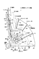
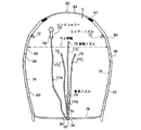
図1には、本実施例に係る携帯用シャワー装置の概略側面図が示されている。この図において、携帯用シャワー装置10は、健常者はもとより、高齢者や身体の不自由な介護対象者の入浴に適用されるものであり、防水パン12と、この防水パン12の上部を閉蓋可能な蓋部13と、これら防水パン12と蓋部13との間に配置され、折り畳み可能な蛇腹状のカバー部としてのカバー部14と、これら防水パン12、蓋部13、及びカバー部14の内部に形成される入浴空間Sに湯水を噴出可能なシャワー部16とを備えて構成されている。なお、以下においては、特に明示しない限り、図1中右側を「前」、同左側を「後」と称するとともに、図1中紙面直交方向を「幅方向」と称することとする。
【0015】
前記防水パン12は、図2にも示されるように、携帯用シャワー装置10の床面をなす底壁18と、この底壁18の外周に沿って立設される側壁19とを備えて構成されている。底壁18は、その内部に図2中上下方向すなわち前後方向に沿って内部通路21が形成される他、その外面18A(図1参照)の前方に前輪22が回転可能に支持されるとともに、その内面18Bの後方に排水口23が形成されている。
【0016】
前記内部通路21は、図2中左右方向すなわち幅方向における両端側にそれぞれ設けられており、それらの前端側には、円弧状に形成された移動用把手24を支持する把手支持パイプ25が進退可能に挿入されている。これによって、移動用把手24は、防水パン12の外側に配置されて前後方向に進退可能となる。また、各内部通路21の後端側には、幅方向両側に配置される後輪26を回転可能に支持する後輪支持パイプ27が進退可能に挿入され、これによって、進行方向に沿う前後輪22,26の離間幅が調整可能になる。ここで、各支持パイプ25,27は、内部通路21内の任意の位置で係合可能になっており、移動用把手24及び後輪26の前後方向の移動を規制可能になっている。なお、前記係合を解除する手段としては、特に限定されるものではないが、移動用把手24や後輪26に所定以上の強制力を前後方向に付与して前記係合を解除する構造や、押しボタンやレバー等の操作によって前記係合を解除する構造のものを採用することができる。
【0017】
前記前輪22は、後輪26より小径に設定されており、これによって、携帯用シャワー装置10の全体をより安定した状態で設置可能となる。なお、前輪22は、後輪26よりも若干幅方向内側に配置されており、その直径は、前輪22及び後輪26を略水平面に接地させたときに、防水パン12が略水平となるように、後輪26の直径と相対的に設定される。
【0018】
前記排水口23は、幅方向略中央に形成されるとともに、図2のA−A線矢視断面図である図3にも示されるように、底壁18の後側に設けられた排水路29に連通する。このため、防水パン12内に流れた湯水は、その後方から外部に排水可能となる。ここで、底壁10の内面18Bは、排水口23に向かう水勾配を備えた形状となっており、これによって、防水パン12に流れた湯水の排水が促進される。また、排水路29は、その出口部29A近傍で、シャワー装置10と別体のポンプ装置P(図9参照)に接続可能となっている。
【0019】
前記側壁19は、その後部側がその他の領域より高くなる形状となっており、その後端には、幅方向略中央に給水口30が形成されている。給水口30は、防水パン12の外側から前記ポンプ装置Pに接続可能になっているとともに、防水パン12の内側に位置する給水管32に接続されるようになっている。給水管32には、当該給水管32と前記シャワー部16とを接続するための給水接続管34が複数取り付けられている。
【0020】
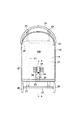
前記蓋部13は、図4にも示されるように、同図中正面側が開放する形状に設けられ、防水パン12の上部を略収容可能となる大きさに設けられている。具体的に、蓋部13は、頂壁36と、頂壁36の外周縁に連なる側壁37とを備えて構成されている。頂壁36の外面36A(図1参照)側には、主として蓋部13の開閉に用いられる平面視略U字状の開閉用把手39が取り付けられている。一方、頂壁36の内面36B側、すなわち蓋部13の内面側には、図4中上側に位置するヘッドレスト41と、このヘッドレスト41の同図中下方に位置する椅子43とが設けられている。ヘッドレスト41は、図4中上下方向に取り付けられたガイドレール44に沿って移動可能となっており、これによって、ヘッドレスト41の高さ調整が可能となっている。
【0021】
前記椅子43は、蓋部13の内面36Bに一体的に形成された背部47と、この背部47の図4中左右両側で回転可能に支持されるとともに、同図中紙面直交方向に長さ調整可能な肘掛け部48と、背部47の下端側に位置し、蓋部13の回転に伴って変位可能な座部49と、この座部49の下方に位置する脚部50とを備えて構成されている。
【0022】
前記背部47は、頂壁36の内面36Bより内側に隆起する形状に設けられている。ここで、背部47には、内側に凹状の排水溝52が形成されているとともに、内部に背フレーム53が固定されている。排水溝52は、図4中上下方向に沿って二箇所設けられており、その上方から防水パン12側への排水の通過を許容可能となっている。背フレーム53は、背部47の下端の図4中左右両側から下方に突出するようになっており、その下端側は、前記防水パン12の底壁18側と回転可能に接続されている。これにより、背フレーム53が固定される蓋部13と防水パン12とが相対回転可能となる。特に、図4中左側に位置する背フレーム53の下端側には、防水パン12との相対回転角度を複数段階で保持可能な角度保持機構54が設けられている。この角度保持機構54は、特に限定されるものではないが、防水パン12側に固定されるギザ歯の谷間に、背フレーム53側に設けられたフックが係合するいわゆるラチエット構造となっており、その係合位置によって、前記相対回転角度を複数段階で変えることができるようになっている。なお、前記ギザ歯にフックが係合した係合状態にあっては、防水パン12に対する蓋部13の相対回転が規制されるようになっており、この規制の解除は、図示省略したレバーを操作すること等によって行われる。従って、当該レバーを操作して蓋部13の回転すれば、一旦設定した蓋部13と防水パン12の相対回転角度を変えて背部47をリクライニングさせることが可能となる。
【0023】
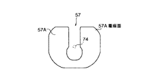
前記座部49は、前記背フレーム53に回転可能に接続される座フレーム55と、この座フレーム55に相対回転可能に支持される座板57とから構成されている。座板57には、図5に示されるように、入浴者H(図1参照)の尻の左右両側を分散して支持可能な二股状の着座面57Aが形成されている。脚部50は、図1及び図4に示されるように、その一端50A側が、座フレーム55の前側で相対回転可能に連結される一方、その他端50B側が、前記防水パン12の底壁18側と相対回転可能に連結されている。以上において、背フレーム53と座フレーム55と脚部50とによってリンク機構が構成され、座部49は、蓋部13の回転に伴って変位可能となる。すなわち、蓋部13を回転して、シャワー装置10を図1に示される使用状態に設定すると、座部49は、入浴者Hが着座可能な位置に設定される一方、その状態から、蓋部13を同図中時計方向に回転すると、座部49は、その着座面57Aが背部47に対面する方向に回転して折り畳まれる。また、座板57は、特に限定されるものではないが、座フレーム55に対して約180度回転可能となっている。このため、身体の不自由な入浴者H等をシャワー装置10の内側に入れる場合に、入浴者Hの脚部をシャワー装置10の外部に残しながら入浴者Hを座板57に着座させた後、当該座板57を回転すれば、入浴者Hの全身を容易にシャワー装置10の内側に配置させることができ、介護作業の一層の効率化を図ることができる。
【0024】
前記カバー部14は、図1に示されるように、防水パン12の側壁19の後部内側に回転可能に支持される複数の骨部材60と、各骨部材60間に張設される張設部材としての張設部材61とを備えて構成されている。骨部材60は、図6に示されるように、同図中左右両側すなわち前記幅方向両側に位置する太パイプ63と、これら各太パイプ63の図6中上端間を掛け渡す細パイプ64とによって構成されている。太パイプ63は、図6中下端側が前記側壁19に回転可能に支持されるとともに、その途中に幅方向の曲げを促進する関節部66が設けられている。細パイプ64は、その両端側が太パイプ63の内部に収容されており、ばね67によって骨部材60の上部幅Wを拡開する方向に突っ張られるようになっている。張設部材61は、図7に示されるように、同図中下端縁側すなわち後端縁側に、入浴者Hの首部を通す円弧状の首出し口69が形成されており、同図に示される使用状態において入浴空間Sの内部に位置する入浴者Hの身体を包み込むようになっている。なお、首出し口69と、それに近接する骨部材60との間には、ファスナー70が設けられている。また、張設部材61は、前記骨部材60に対して着脱自在に設けられている。具体的に、特に限定されるものではないが、骨部材60及び張設部材61には、パイル布とフック布とからなる図示しない接着面テープがそれぞれ設けられ、それら各接着面テープの係脱によって、前記着脱が可能となる。これにより、張設部材61のみの洗濯や交換を行うことができる他、デザインの異なる他の張設部材61の交換も容易となる。
【0025】
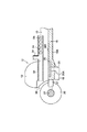
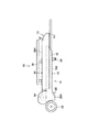
前記シャワー部16は、図6に示されるように、各骨部材60の内側に複数配置されるシャワーノズル72と、吐水口を任意の位置に移動可能なハンドシャワー73と、椅子43の座部49の近傍に設けられる着座ノズル74と、蓋部13の内面側に設けられる背部ノズル75とによって構成されている。シャワーノズル72は、太パイプ63の内部に配置された給水パイプ76を介して前記給水接続管34に接続され、給水管32からの湯水を入浴空間Sに噴出可能となっている。ハンドシャワー73、着座ノズル74、及び背部ノズル75も同様に、給水接続管34から延びる給水パイプ77A,77B,77Cにそれぞれ接続され、給水管32からの湯水を入浴空間Sに噴出可能となっている。ここで、ハンドシャワー73は、蓋部13の内面36B側に設けられたシャワーフック79に保持させることができるようになっている。また、着座ノズル74は、図5に示されるように、その先端が前記二股状の着座面57Aの間に位置し、椅子43に着座した入浴者Hの尻に向かって湯水を噴出可能となっているとともに、前後方向すなわち図5中上下方向に移動可能となっている。更に、背部ノズル75は、図4に示されるように、各排水溝52の内部と、ヘッドレスト41の近傍に設けられている。なお、特に限定されるものではないが、各ノズル72,74,75の位置を移動或いは回転可能にしたり、吐水領域を任意に変更可能にしてもよく、また、各ノズル72,74,75からの吐出水勢の強弱を任意に設定可能にすることもできる。
【0026】
次に、本実施例に係る携帯用シャワー装置10の使用方法について説明する。
【0027】
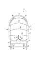
まず、シャワー装置10を使用しない場合には、図1に示される使用状態から、骨部材60を同図中時計方向に回転させることにより、カバー部14を折り畳んで防水パン12の内部に収容した後、蓋部13を同図中時計方向に回転させ、図8に示されるように、蓋部13の内側に、防水パン12の一部を収容することにより、シャワー装置10を折り畳む。この状態では、カバー部14及び椅子43の座部49は、防水パン12と蓋部13との間の内部空間にそれぞれ折り畳まれて収容されることになる。これによって、シャワー装置10を使用しない場合には、その使用時よりコンパクトにすることができ、寝室の隅や押入等にも難なく収納できる他、その移動も容易となる。
【0028】
そして、図8の折り畳み状態から、同シャワー装置10を使用する場合には、当該シャワー装置10を収納場所等から移動し、介護対象者の寝室のベッド近傍等の所定の使用場所に設置する。そして、図9に模式的に示されるように、シャワー装置10と別体となるポンプ装置Pをシャワー装置10の近傍に設置し、防水パン12の排水路29及び給水口30に接続する。ここで、ポンプ装置Pは、水源としての浴槽等の貯湯槽T1からシャワー装置10に湯水を供給する給水ポンプ80と、防水パン12に溜まった湯水を強制的に排水槽T2に排水する排水ポンプ81と、これら各ポンプ80,81の作動及び停止等をリモコン操作するリモコン装置82とを備えて構成されている。ところで、給水ポンプ80には、入浴者Hの感染症防止等のための消毒液が消毒液槽T3から供給されるようになっており、これにより、シャワー装置10側には、貯湯槽T1からの湯水と消毒液槽T3からの消毒液とを混合した混合洗浄水が供給される。なお、給水ポンプ80には、家庭の水栓の蛇口等から温水を直接供給してもよく、また、排水ポンプ81からの排水は、風呂や洗面台の排水管等に直接排出してもよい。
【0029】
以上の準備が整った後、蓋部13の外側に取り付けられた開閉用把手39を掴んで、図8中上方に持ち上げながら蓋部13を同図中反時計方向に回転する。すると、図1に示されるように、蓋部13が防水パン12に対して起立し、それに伴って、折り畳まれていた座部49は、入浴者Hが着座可能となる所定の位置に変位する。なお、この状態では、開閉用把手39に、図示しないホースやタオル等を引っ掛けることができる。そして、防水パン12に対して蓋部13が回転しないように、それらを角度保持機構54によってロックし、入浴者Hを座部49に着座させて蓋部13の内面側の背部47に寄り掛からせる。この後、防水パン12の内側に位置する各骨部材60を図1中反時計方向に回転させ、カバー部14を防水パン12側から引き出し、入浴者Hの身体を包み込む。この際、骨部材60は、その回転に伴って前記上部幅Hが拡開することとなり、カバー部14の内部に形成される入浴空間Sは、防水パン12の内側における前記幅方向の寸法よりも幅広となる。また、これと前後して、入浴者Hの頭部がヘッドレスト41に適正に支持されるように、当該ヘッドレスト41をガイドレール44に沿って上下方向に移動し、ヘッドレスト41の位置決めを行う。このように入浴者Hが入浴空間Sに適正に配置された後で、リモコン装置82を操作し、給水ポンプ80を作動させると、前記混合洗浄水が骨部材60の内側の各シャワーノズル72及び背部ノズル75(図4等参照)から噴出し、これにより、入浴者Hの洗体が行われる。この際、カバー部14が入浴者Hの身体を包み込んでいるため、入浴者Hは、発汗が促進され、サウナ室に入室した場合と略同様のサウナ効果を得る。また、リモコン装置82を操作して前記混合洗浄水を着座ノズル74から噴出させることもでき、この場合には、入浴者Hの肛門部及びその周辺の洗浄も可能となる。更に、リモコン装置82を操作して前記混合洗浄水をハンドシャワー73から噴出させることもでき、この場合には、入浴者Hの洗髪等も可能となる。このように入浴者Hの洗髪等をする場合には、図1に示された状態から、角度保持機構54のロックを解除して蓋部13を図1中反時計方向に回転し、図10に示されるように、椅子43の背部47を更に傾けるとよい。なお、洗体に用いられた排水は、防水パン12の内側に流れ落ちて排水口23よりシャワー装置10の外部に排出される。特に、入浴者Hの洗髪に用いられた排水は、背部47に形成された排水溝52(図4参照)を通って防水パン12に流れるようになっている。また、洗体に用いられた排水をシャワー装置10の外部に排出する場合には、リモコン装置82を操作して排水ポンプ81を作動させると、前記排水を排水槽T2にスムースに排出可能となる。
【0030】
以上のような使用態様の他に、図11に示されるように、カバー部14を防水パン12側から中間位置まで引き出し、カバー部14と蓋部13との間に脱着式のサイドテント90を設置し、上部開放型の入浴空間Sを形成することも可能である。これによって、介護者等が入浴者Hを動かしながら洗体することができ、介護を必要とする入浴者Hに好適となる。
【0031】
そして、入浴者Hの洗体が終わった後は、前述と逆の動作でカバー部14を防水パン12の内部に収容した後、入浴者Hをシャワー装置10の外側に移動させて、蓋部13を図1中時計方向に回転して防水パン12を閉蓋する。ここで、カバー部14を防水パン12に収容する際には、骨部材60に、その長さを短くする方向に強制的な外力を付与しながら、当該骨部材60を図1中時計方向に回転すればよい。このようにすると、骨部材60に設けられたばね67(図6参照)に抗して、各太パイプ63(同図参照)の内部に収容される細パイプ64(同図参照)の部分が増し、骨部材60の長さが短くなって、カバー部14を防水パン12の内側に収容可能となる。なお、カバー部14が防水パン12に収容された状態では、その側壁19に骨部材60が接触してその拡開が規制されるようになっている。
【0032】
従って、このような実施例によれば、携帯用シャワー装置10を使用しないときには、蓋部13の回転によって防水パン12を閉蓋することにより、当該カバー部14や座部49等は、蓋部13と防水パン12との間の内部空間に収容されるため、同シャワー装置10の全体をコンパクトに折り畳むことができ、不使用時における収納性や運搬性を向上できるという効果を得る。この際、カバー部14を取り外すことができるとともに、シャワー装置10を立て掛けて収納することができ、カバー部14を含むシャワー装置10の完全な水切り、乾燥が可能となり、シャワー装置10をより清潔に保持することができる。
【0033】
また、同シャワー装置10のセット及び折り畳みの際には、ドライバー等の工具が不要で、蓋部13及びカバー部14の回転によって行うことができるため、シャワー装置10のセット及び折り畳み作業をいわゆるワンタッチで行うことができるという効果も得る。
【0034】
なお、本発明における装置各部の構成は図示構成例に限定されるものではなく、実質的に同様の作用を奏する限りにおいて、種々の変更が可能である。
【0035】
【発明の効果】
以上説明したように、本発明によれば、蓋部によって防水パンを閉蓋したときには、カバー部が当該防水パンと蓋部との間の内部空間に収容される一方、蓋部によって防水パンを開蓋したときには、カバー部が防水パンと蓋部との間に位置する入浴者を被覆し、所定の入浴空間を形成可能に設けたから、蓋部の開閉によって、シャワー装置全体をコンパクトに折り畳むことができ、シャワー装置の収納性や運搬性を向上させることができる。
【0036】
また、防水パンに移動機構を設け、この移動機構を防水パンに支持される複数の車輪によって構成し、進行方向に沿う車輪の離間幅を調整可能に設けたから、シャワー装置の移動を一層容易に行うことができる他、使用状態において、装置全体をより安定して支持することができる。
【0037】
更に、前記カバー部を前記防水パンに相対回転可能に支持される骨部材と、各骨部材間に張設される張設部材とにより構成し、前記カバー部が入浴者を被覆する使用状態に設定されると、骨部材の上部幅を拡開可能に設けたから、シャワー装置の折り畳み時におけるコンパクト性を損ねずに、入浴空間をより十分な広さとすることができる。
【0038】
また、前記シャワー部を構成するシャワーノズルを前記骨部材に配置し、前記カバー部の内側に湯水を噴出可能に設けたから、シャワー装置を使用状態にセットする作業やその折り畳み作業を一層容易に行うことができる。
【図面の簡単な説明】
【図1】 本実施例に係る携帯用シャワー装置の概略側面図。
【図2】 防水パンの概略平面図。
【図3】 図2のA−A線矢視拡大断面図。
【図4】 防水パン及び蓋部を示す概略断面正面図。
【図5】 座板の概略平面図。
【図6】 骨部材をシャワー部とともに示す概略正面図。
【図7】 図1の概略平面図。
【図8】 図1の折り畳み状態を示す概略側面図。
【図9】 携帯用シャワー装置の給排水について説明するための模式図。
【図10】 図1のリクライニング状態を示す概略側面図。
【図11】 他の使用形態を説明するための携帯用シャワー装置の概略側面図。
【符号の説明】
10・・・携帯用シャワー装置、12・・・防水パン、13・・・蓋部、14・・・カバー部、16・・・シャワー部、22・・・前輪(車輪)、23・・・排水口、30・・・給水口、26・・・後輪(車輪)、41・・・ヘッドレスト、43・・・椅子、47・・・背部、49・・・座部、50・・・脚部(リンク機構)、53・・・背フレーム(リンク機構)、54・・・角度保持機構、55・・・座フレーム(リンク機構)、57・・・座板、57A・・・着座面、60・・・骨部材、61・・・張設部材、72・・・シャワーノズル、73・・・ハンドシャワー、74・・・着座ノズル、75・・・背部ノズル、T1・・・貯湯槽、S・・・入浴空間、H・・・入浴者、P・・・ポンプ装置、W・・・上部幅[0001]
BACKGROUND OF THE INVENTION
The present invention relates to a portable shower device, and more particularly to a portable shower device that can be folded compactly and is convenient for storage and movement when not in use.
[0002]
[Prior art]
Recently, for example, Japanese Patent Laid-Open No. 8-154858 and Japanese Patent Laid-Open No. 10-192357 are proposed in order to reduce the work of bathing care recipients such as physically handicapped persons and bedridden elderly persons. As described above, various care shower devices that can be moved have appeared. The shower device disclosed in Japanese Patent Application Laid-Open No. 8-154858 can accommodate the body of a bather together with the wheelchair that has transported the bather, and bathes by bathing hot water toward the body housed inside the device. The body can be washed. Moreover, the shower apparatus of Unexamined-Japanese-Patent No. 10-192357 consists of the mounting base which a bather can lie down, and the bathtub main body which has a bellows-shaped bathtub sheet | seat, The said bather is placed on a mounting base. After bathing, the bather can be washed by covering the bather with a bathtub sheet and supplying warm water therein.
[0003]
[Problems to be solved by the invention]
In general, a care shower device is required to be installed adjacent to a care recipient's bedroom, etc., in order to reduce transportation work of the care recipient to the shower device. When not in use, a device that can be moved to a predetermined storage location is required to reduce dead space such as a bedroom. However, since each of the shower devices has a bathing space in which the bather can be located, the size of the shower device is necessarily larger than that of the bather, and the shower device cannot be folded compactly when not in use. Therefore, even if it can be installed adjacent to the bedroom or the like of the care recipient, there is an inconvenience that it is difficult to store or move. That is, since each shower device is still large even when not in use, it cannot be stored in a corner or a closet of the bedroom when not in use, and a different storage room away from the bedroom. Have to go to. In addition, when the shower device is moved, it is difficult to pass through the doorstep and the step on the floor because of its large size. Therefore, in each said shower apparatus, a great effort is required for the movement operation | work, and this becomes a factor which increases the burden of a care work. Furthermore, since it becomes difficult to carry the shower device by car, it is necessary to install the shower device door-to-door at the home of the care recipient, and the device cannot be used efficiently.
[0004]
OBJECT OF THE INVENTION
The present invention has been devised by paying attention to such inconveniences, and its purpose is to realize a narrow space required for storage when not in use and to move to an arbitrary place. An object of the present invention is to provide a portable shower device that can be easily performed.
[0005]
[Means for Solving the Problems]
In order to achieve the above object, the present invention provides a waterproof pan, a lid that is rotatably supported by the waterproof pan, and capable of closing the waterproof pan, and between the waterproof pan and the lid. A cover part that is arranged and foldable, and a shower part that can eject hot water from a predetermined water source in a space surrounded by the waterproof pan and the lid part,
The cover part isA bone member that is supported by the waterproof pan so as to be rotatable relative to each other and that is configured to cover the bather so that the upper width can be widened. A tension member to be provided,When the waterproof pan is in a closed state, the waterproof pan is accommodated in an internal space between the waterproof pan and the lid portion. On the other hand, when the waterproof pan is in an open state, the waterproof pan and the lid portion are The construction is such that a bather located between them is covered and a predetermined bathing space can be formed. According to such a configuration, a predetermined bathing space is formed by opening the waterproof pan and pulling out the cover portion, while closing the waterproof pan between the waterproof pan and the lid portion. Since the cover part is folded and accommodated in the interior space, when using the shower device, a bathing space sufficiently wide for washing can be formed. On the other hand, when the shower device is not used, the shower device is used. Can be folded in a compact manner, thereby making it possible to reduce the space required for storage and to easily move to any place.Moreover, while the cover portion can be accommodated in a compact manner, the bathing space in use can be made sufficiently large, and the space for the bather to move his arm can be secured to improve usability. be able to.
[0006]
DETAILED DESCRIPTION OF THE INVENTION
The waterproof pan according to the present invention preferably has a configuration in which a predetermined moving mechanism is provided. By comprising in this way, a shower apparatus can be made still easier to move. Here, the moving mechanism may be configured by a plurality of wheels supported by the waterproof pan, and may be configured to be capable of adjusting the separation width of the wheels along the traveling direction. According to this, it is possible to change the center of gravity position by adjusting the separation width of the wheel according to the opening angle of the lid, and it is possible to support the entire apparatus more stably.
[0007]
Also,PreviousIt is preferable that the tension member is detachably provided. This makes it easy to clean and dry the tension member that forms the bathing space, facilitates the work of maintaining its sanitary condition, and allows replacement when it is aged. The tension member can be selectively attached.
[0008]
Furthermore,PreviousThe shower portion includes a shower nozzle disposed on the bone member, and the shower nozzle is provided inside the cover portion so as to be able to eject hot water. With such a configuration, it becomes possible to set the shower nozzle in a predetermined position along with the folding of the cover part, and to store it in the waterproof pan. Work can be performed more easily.
[0009]
Further, a back portion of the chair is formed on the inner surface side of the lid portion, and a seat portion of the chair is provided, and the seat portion of the chair is provided so as to be displaceable with the rotation of the lid portion by a predetermined link mechanism. When the lid is closed, it is accommodated in the internal space between the waterproof pan and the lid, while it is displaced to a seatable position when the lid is opened. preferable. According to such a structure, a chair can be set simultaneously by opening a waterproof pan, and the operation | work which sets a shower apparatus to a use condition can be performed still more easily. Here, the waterproof pan may be provided with an angle holding mechanism capable of holding a relative rotation angle with the lid in a plurality of stages. This makes it possible to recline the back from a state where the bather is seated on the chair, making it possible to wash the hair without getting the bather's face wet, etc. it can. The shower portion further includes a seating nozzle disposed in the vicinity of the seat portion, and the seat portion includes a seat plate formed with a bifurcated seating surface that supports the left and right sides of the bather's buttocks. It is also possible to employ a configuration in which the seating nozzle is provided so that hot water can be ejected from between the bifurcated seating surfaces toward the bather's buttocks. According to such a configuration, it becomes possible to clean the bather's anus and its surroundings, and in particular, it is possible to provide a highly practical shower apparatus for those who have a handicapped arm.
[0010]
Furthermore, a headrest whose height can be adjusted may be provided on the inner surface of the lid. According to this, it is possible to support the bather's head at an appropriate position according to the sitting height of each bather, thereby enabling bathing while leaning against the lid side, and more care-giving persons, etc. You can bathe comfortably.
[0011]
Moreover, it is preferable that the shower unit further includes a hand shower that can arbitrarily move the water outlet. By comprising in this way, a bather's hair washing etc. can be performed easily.
[0012]
Further, the waterproof pan is provided with a water supply port for supplying hot water from the drain port and the water source to the shower unit, and the water supply port and / or the drain port can be connected to a separate pump device. A configuration of being provided can also be employed. With such a configuration, it is not necessary to incorporate the pump device into the shower device, and the entire device can be reduced in weight and size, which is more advantageous in storing and moving the device.
[0013]
【Example】
Embodiments of the present invention will be described below with reference to the drawings.
[0014]
FIG. 1 shows a schematic side view of a portable shower device according to the present embodiment. In this figure, a
[0015]
As shown in FIG. 2, the
[0016]
The
[0017]
The
[0018]
The
[0019]
The
[0020]
As shown in FIG. 4, the
[0021]
The
[0022]
The
[0023]
The
[0024]
As shown in FIG. 1, the
[0025]
As shown in FIG. 6, the
[0026]
Next, the usage method of the
[0027]
First, when the
[0028]
And when using the
[0029]
After the above preparation is completed, the opening / closing
[0030]
In addition to the use mode as described above, as shown in FIG. 11, the
[0031]
And after the bather H's washing is finished, the
[0032]
Therefore, according to such an embodiment, when the
[0033]
Further, when the
[0034]
The configuration of each part of the apparatus in the present invention is not limited to the illustrated configuration example, and various modifications are possible as long as substantially the same operation is achieved.
[0035]
【The invention's effect】
As described above, according to the present invention, when the waterproof pan is closed with the lid, the cover is accommodated in the internal space between the waterproof pan and the lid, while the waterproof pan is When the lid is opened, the cover part covers the bather located between the waterproof pan and the lid part, and a predetermined bathing space can be formed, so that the entire shower device can be folded compactly by opening and closing the lid part. It is possible to improve the stowability and transportability of the shower device.
[0036]
In addition, a movement mechanism is provided on the waterproof pan, and the movement mechanism is configured by a plurality of wheels supported by the waterproof pan, and the separation width of the wheels along the traveling direction is provided to be adjustable. In addition, the entire apparatus can be supported more stably in the state of use.
[0037]
Furthermore, the cover portion is constituted by a bone member that is rotatably supported by the waterproof pan, and a tension member stretched between the bone members, and the cover portion covers a bather. When set, the upper width of the bone member is provided so that it can be expanded, so that the bathing space can be made sufficiently wide without compromising the compactness when folding the shower device..
[0038]
Moreover, since the shower nozzle which comprises the said shower part is arrange | positioned in the said bone member, and it provided so that hot water could be ejected inside the said cover part, the operation | work which sets a shower apparatus to a use condition and its folding operation | work are performed more easily. be able to.
[Brief description of the drawings]
FIG. 1 is a schematic side view of a portable shower device according to an embodiment.
FIG. 2 is a schematic plan view of a waterproof pan.
3 is an enlarged sectional view taken along line AA in FIG. 2;
FIG. 4 is a schematic sectional front view showing a waterproof pan and a lid.
FIG. 5 is a schematic plan view of a seat plate.
FIG. 6 is a schematic front view showing a bone member together with a shower portion.
7 is a schematic plan view of FIG. 1. FIG.
FIG. 8 is a schematic side view showing the folded state of FIG. 1;
FIG. 9 is a schematic diagram for explaining water supply / drainage of a portable shower device.
10 is a schematic side view showing the reclining state of FIG. 1; FIG.
FIG. 11 is a schematic side view of a portable shower device for explaining another usage pattern.
[Explanation of symbols]
DESCRIPTION OF
Claims (3)
前記カバー部は、前記防水パンに相対回転可能に支持されるとともに、前記カバー部が入浴者を被覆する使用状態に設定されると、上部幅を拡開可能に設けられる骨部材と、各骨部材間に張設される張設部材とを備え、前記防水パンを閉蓋状態にしたときに、当該防水パンと蓋部との間の内部空間に収容される一方、前記防水パンを開蓋状態にしたときに、前記防水パンと蓋部との間に位置する入浴者を被覆し、所定の入浴空間を形成可能に設けられていることを特徴とする携帯用シャワー装置。A waterproof pan, a lid that is rotatably supported by the waterproof pan, and capable of closing the waterproof pan; and a cover that is disposed between the waterproof pan and the lid and can be folded; and Provided with a shower part capable of ejecting hot water from a predetermined water source in a space surrounded by the waterproof pan and the lid part,
The cover portion is supported by the waterproof pan so as to be relatively rotatable, and when the cover portion is set to a use state covering the bather, a bone member provided to expand the upper width, and each bone A tension member stretched between the members , and when the waterproof pan is in a closed state, the waterproof pan is accommodated in an internal space between the waterproof pan and the lid, while the waterproof pan is opened. A portable shower device that is provided so as to cover a bather located between the waterproof pan and the lid and form a predetermined bathing space when in a state.
Priority Applications (1)
| Application Number | Priority Date | Filing Date | Title |
|---|---|---|---|
| JP30208199A JP3690210B2 (en) | 1999-10-25 | 1999-10-25 | Portable shower device |
Applications Claiming Priority (1)
| Application Number | Priority Date | Filing Date | Title |
|---|---|---|---|
| JP30208199A JP3690210B2 (en) | 1999-10-25 | 1999-10-25 | Portable shower device |
Publications (2)
| Publication Number | Publication Date |
|---|---|
| JP2001120633A JP2001120633A (en) | 2001-05-08 |
| JP3690210B2 true JP3690210B2 (en) | 2005-08-31 |
Family
ID=17904704
Family Applications (1)
| Application Number | Title | Priority Date | Filing Date |
|---|---|---|---|
| JP30208199A Expired - Fee Related JP3690210B2 (en) | 1999-10-25 | 1999-10-25 | Portable shower device |
Country Status (1)
| Country | Link |
|---|---|
| JP (1) | JP3690210B2 (en) |
Families Citing this family (3)
| Publication number | Priority date | Publication date | Assignee | Title |
|---|---|---|---|---|
| JP2008540020A (en) * | 2005-05-17 | 2008-11-20 | オハド パズ, | Multi-position support device with electric foot support |
| JP2009018006A (en) * | 2007-07-11 | 2009-01-29 | Sakai Medical Co Ltd | Stretcher apparatus for bathing |
| JP4648481B1 (en) * | 2009-12-07 | 2011-03-09 | ▲高▼橋 厚子 | Simple bathtub |
-
1999
- 1999-10-25 JP JP30208199A patent/JP3690210B2/en not_active Expired - Fee Related
Also Published As
| Publication number | Publication date |
|---|---|
| JP2001120633A (en) | 2001-05-08 |
Similar Documents
| Publication | Publication Date | Title |
|---|---|---|
| US7537069B2 (en) | Home care equipment system | |
| US8141184B2 (en) | Portable personal hygiene apparatus | |
| KR20070032763A (en) | Full seatable toilet seat | |
| JP3690210B2 (en) | Portable shower device | |
| JPWO2006008794A1 (en) | Self-automatic hair washing and self-care device for hair and scalp | |
| JP4606914B2 (en) | Foot bath chair | |
| JP2003024410A (en) | Care bath | |
| JP3499549B1 (en) | Irrigation bath | |
| JPH07241251A (en) | Bathtub | |
| JP7305145B2 (en) | bathing equipment | |
| JP3118539B2 (en) | Body washing device | |
| JP2013525205A (en) | Infant car seat | |
| JP3787937B2 (en) | Shower equipment | |
| JP2006263150A (en) | Shower apparatus | |
| JP3741988B2 (en) | Nursing bath equipment | |
| JPH06154278A (en) | Mobile bathing vehicle | |
| JP2008110181A (en) | Portable and mobile shampoo stand | |
| JP2003310686A (en) | Shower apparatus | |
| JP3067564U (en) | Shower chair | |
| JPH10127511A (en) | Simple foldable bathtub and foldable bathing chair | |
| JP5732610B2 (en) | Shower bath equipment | |
| KR100576055B1 (en) | Hair cleaning bed for beauty shop | |
| JPH09271508A (en) | Shower apparatus for person in sitting position | |
| JP2001017504A (en) | Bathing device | |
| KR200395187Y1 (en) | movable washstand for bathroom |
Legal Events
| Date | Code | Title | Description |
|---|---|---|---|
| A977 | Report on retrieval |
Free format text: JAPANESE INTERMEDIATE CODE: A971007 Effective date: 20041014 |
|
| A131 | Notification of reasons for refusal |
Free format text: JAPANESE INTERMEDIATE CODE: A131 Effective date: 20041116 |
|
| A521 | Written amendment |
Free format text: JAPANESE INTERMEDIATE CODE: A523 Effective date: 20050113 |
|
| TRDD | Decision of grant or rejection written | ||
| A01 | Written decision to grant a patent or to grant a registration (utility model) |
Free format text: JAPANESE INTERMEDIATE CODE: A01 Effective date: 20050524 |
|
| A61 | First payment of annual fees (during grant procedure) |
Free format text: JAPANESE INTERMEDIATE CODE: A61 Effective date: 20050606 |
|
| R150 | Certificate of patent or registration of utility model |
Free format text: JAPANESE INTERMEDIATE CODE: R150 |
|
| S531 | Written request for registration of change of domicile |
Free format text: JAPANESE INTERMEDIATE CODE: R313532 |
|
| R350 | Written notification of registration of transfer |
Free format text: JAPANESE INTERMEDIATE CODE: R350 |
|
| FPAY | Renewal fee payment (event date is renewal date of database) |
Free format text: PAYMENT UNTIL: 20080624 Year of fee payment: 3 |
|
| FPAY | Renewal fee payment (event date is renewal date of database) |
Free format text: PAYMENT UNTIL: 20090624 Year of fee payment: 4 |
|
| LAPS | Cancellation because of no payment of annual fees |