EP1895112B1 - Ventiltrieb eines motors - Google Patents
Ventiltrieb eines motors Download PDFInfo
- Publication number
- EP1895112B1 EP1895112B1 EP06766947A EP06766947A EP1895112B1 EP 1895112 B1 EP1895112 B1 EP 1895112B1 EP 06766947 A EP06766947 A EP 06766947A EP 06766947 A EP06766947 A EP 06766947A EP 1895112 B1 EP1895112 B1 EP 1895112B1
- Authority
- EP
- European Patent Office
- Prior art keywords
- camshaft
- cylinder head
- rocker arm
- bearing
- supported
- Prior art date
- Legal status (The legal status is an assumption and is not a legal conclusion. Google has not performed a legal analysis and makes no representation as to the accuracy of the status listed.)
- Not-in-force
Links
- 230000000452 restraining effect Effects 0.000 claims description 5
- 239000003921 oil Substances 0.000 description 38
- 230000005540 biological transmission Effects 0.000 description 17
- 230000003014 reinforcing effect Effects 0.000 description 7
- 238000005461 lubrication Methods 0.000 description 4
- 239000003595 mist Substances 0.000 description 4
- 238000002485 combustion reaction Methods 0.000 description 3
- 230000001050 lubricating effect Effects 0.000 description 3
- 230000002093 peripheral effect Effects 0.000 description 3
- 230000010349 pulsation Effects 0.000 description 3
- 230000000694 effects Effects 0.000 description 2
- 230000002708 enhancing effect Effects 0.000 description 2
- 230000001965 increasing effect Effects 0.000 description 2
- 238000001816 cooling Methods 0.000 description 1
- 239000010687 lubricating oil Substances 0.000 description 1
- 238000012423 maintenance Methods 0.000 description 1
- 238000000034 method Methods 0.000 description 1
- 239000007858 starting material Substances 0.000 description 1
Images


Classifications
-
- F—MECHANICAL ENGINEERING; LIGHTING; HEATING; WEAPONS; BLASTING
- F01—MACHINES OR ENGINES IN GENERAL; ENGINE PLANTS IN GENERAL; STEAM ENGINES
- F01L—CYCLICALLY OPERATING VALVES FOR MACHINES OR ENGINES
- F01L1/00—Valve-gear or valve arrangements, e.g. lift-valve gear
- F01L1/02—Valve drive
-
- F—MECHANICAL ENGINEERING; LIGHTING; HEATING; WEAPONS; BLASTING
- F01—MACHINES OR ENGINES IN GENERAL; ENGINE PLANTS IN GENERAL; STEAM ENGINES
- F01L—CYCLICALLY OPERATING VALVES FOR MACHINES OR ENGINES
- F01L1/00—Valve-gear or valve arrangements, e.g. lift-valve gear
- F01L1/12—Transmitting gear between valve drive and valve
- F01L1/18—Rocking arms or levers
-
- F—MECHANICAL ENGINEERING; LIGHTING; HEATING; WEAPONS; BLASTING
- F01—MACHINES OR ENGINES IN GENERAL; ENGINE PLANTS IN GENERAL; STEAM ENGINES
- F01L—CYCLICALLY OPERATING VALVES FOR MACHINES OR ENGINES
- F01L1/00—Valve-gear or valve arrangements, e.g. lift-valve gear
- F01L1/02—Valve drive
- F01L1/022—Chain drive
-
- F—MECHANICAL ENGINEERING; LIGHTING; HEATING; WEAPONS; BLASTING
- F01—MACHINES OR ENGINES IN GENERAL; ENGINE PLANTS IN GENERAL; STEAM ENGINES
- F01L—CYCLICALLY OPERATING VALVES FOR MACHINES OR ENGINES
- F01L1/00—Valve-gear or valve arrangements, e.g. lift-valve gear
- F01L1/02—Valve drive
- F01L1/024—Belt drive
-
- F—MECHANICAL ENGINEERING; LIGHTING; HEATING; WEAPONS; BLASTING
- F01—MACHINES OR ENGINES IN GENERAL; ENGINE PLANTS IN GENERAL; STEAM ENGINES
- F01L—CYCLICALLY OPERATING VALVES FOR MACHINES OR ENGINES
- F01L1/00—Valve-gear or valve arrangements, e.g. lift-valve gear
- F01L1/02—Valve drive
- F01L1/04—Valve drive by means of cams, camshafts, cam discs, eccentrics or the like
- F01L1/047—Camshafts
- F01L1/053—Camshafts overhead type
-
- F—MECHANICAL ENGINEERING; LIGHTING; HEATING; WEAPONS; BLASTING
- F01—MACHINES OR ENGINES IN GENERAL; ENGINE PLANTS IN GENERAL; STEAM ENGINES
- F01L—CYCLICALLY OPERATING VALVES FOR MACHINES OR ENGINES
- F01L1/00—Valve-gear or valve arrangements, e.g. lift-valve gear
- F01L1/12—Transmitting gear between valve drive and valve
- F01L1/18—Rocking arms or levers
- F01L1/181—Centre pivot rocking arms
-
- F—MECHANICAL ENGINEERING; LIGHTING; HEATING; WEAPONS; BLASTING
- F01—MACHINES OR ENGINES IN GENERAL; ENGINE PLANTS IN GENERAL; STEAM ENGINES
- F01L—CYCLICALLY OPERATING VALVES FOR MACHINES OR ENGINES
- F01L1/00—Valve-gear or valve arrangements, e.g. lift-valve gear
- F01L1/46—Component parts, details, or accessories, not provided for in preceding subgroups
-
- F—MECHANICAL ENGINEERING; LIGHTING; HEATING; WEAPONS; BLASTING
- F02—COMBUSTION ENGINES; HOT-GAS OR COMBUSTION-PRODUCT ENGINE PLANTS
- F02F—CYLINDERS, PISTONS OR CASINGS, FOR COMBUSTION ENGINES; ARRANGEMENTS OF SEALINGS IN COMBUSTION ENGINES
- F02F1/00—Cylinders; Cylinder heads
- F02F1/24—Cylinder heads
-
- F—MECHANICAL ENGINEERING; LIGHTING; HEATING; WEAPONS; BLASTING
- F01—MACHINES OR ENGINES IN GENERAL; ENGINE PLANTS IN GENERAL; STEAM ENGINES
- F01L—CYCLICALLY OPERATING VALVES FOR MACHINES OR ENGINES
- F01L1/00—Valve-gear or valve arrangements, e.g. lift-valve gear
- F01L1/12—Transmitting gear between valve drive and valve
- F01L1/18—Rocking arms or levers
- F01L1/181—Centre pivot rocking arms
- F01L1/182—Centre pivot rocking arms the rocking arm being pivoted about an individual fulcrum, i.e. not about a common shaft
-
- F—MECHANICAL ENGINEERING; LIGHTING; HEATING; WEAPONS; BLASTING
- F01—MACHINES OR ENGINES IN GENERAL; ENGINE PLANTS IN GENERAL; STEAM ENGINES
- F01L—CYCLICALLY OPERATING VALVES FOR MACHINES OR ENGINES
- F01L1/00—Valve-gear or valve arrangements, e.g. lift-valve gear
- F01L1/20—Adjusting or compensating clearance
-
- F—MECHANICAL ENGINEERING; LIGHTING; HEATING; WEAPONS; BLASTING
- F01—MACHINES OR ENGINES IN GENERAL; ENGINE PLANTS IN GENERAL; STEAM ENGINES
- F01L—CYCLICALLY OPERATING VALVES FOR MACHINES OR ENGINES
- F01L1/00—Valve-gear or valve arrangements, e.g. lift-valve gear
- F01L1/02—Valve drive
- F01L1/04—Valve drive by means of cams, camshafts, cam discs, eccentrics or the like
- F01L1/047—Camshafts
- F01L2001/0476—Camshaft bearings
-
- F—MECHANICAL ENGINEERING; LIGHTING; HEATING; WEAPONS; BLASTING
- F01—MACHINES OR ENGINES IN GENERAL; ENGINE PLANTS IN GENERAL; STEAM ENGINES
- F01L—CYCLICALLY OPERATING VALVES FOR MACHINES OR ENGINES
- F01L2303/00—Manufacturing of components used in valve arrangements
-
- F—MECHANICAL ENGINEERING; LIGHTING; HEATING; WEAPONS; BLASTING
- F02—COMBUSTION ENGINES; HOT-GAS OR COMBUSTION-PRODUCT ENGINE PLANTS
- F02B—INTERNAL-COMBUSTION PISTON ENGINES; COMBUSTION ENGINES IN GENERAL
- F02B75/00—Other engines
- F02B75/16—Engines characterised by number of cylinders, e.g. single-cylinder engines
- F02B75/18—Multi-cylinder engines
- F02B2075/1804—Number of cylinders
-
- F—MECHANICAL ENGINEERING; LIGHTING; HEATING; WEAPONS; BLASTING
- F02—COMBUSTION ENGINES; HOT-GAS OR COMBUSTION-PRODUCT ENGINE PLANTS
- F02B—INTERNAL-COMBUSTION PISTON ENGINES; COMBUSTION ENGINES IN GENERAL
- F02B2275/00—Other engines, components or details, not provided for in other groups of this subclass
- F02B2275/20—SOHC [Single overhead camshaft]
-
- F—MECHANICAL ENGINEERING; LIGHTING; HEATING; WEAPONS; BLASTING
- F02—COMBUSTION ENGINES; HOT-GAS OR COMBUSTION-PRODUCT ENGINE PLANTS
- F02F—CYLINDERS, PISTONS OR CASINGS, FOR COMBUSTION ENGINES; ARRANGEMENTS OF SEALINGS IN COMBUSTION ENGINES
- F02F7/00—Casings, e.g. crankcases
- F02F7/006—Camshaft or pushrod housings
-
- Y—GENERAL TAGGING OF NEW TECHNOLOGICAL DEVELOPMENTS; GENERAL TAGGING OF CROSS-SECTIONAL TECHNOLOGIES SPANNING OVER SEVERAL SECTIONS OF THE IPC; TECHNICAL SUBJECTS COVERED BY FORMER USPC CROSS-REFERENCE ART COLLECTIONS [XRACs] AND DIGESTS
- Y10—TECHNICAL SUBJECTS COVERED BY FORMER USPC
- Y10T—TECHNICAL SUBJECTS COVERED BY FORMER US CLASSIFICATION
- Y10T74/00—Machine element or mechanism
- Y10T74/20—Control lever and linkage systems
- Y10T74/20576—Elements
- Y10T74/20882—Rocker arms
Definitions
- the present invention relates to an improvement of an engine valve operating system in which a camshaft is supported via a bearing on a cylinder head having an intake valve and an exhaust valve provided therein, and an intake rocker arm and an exhaust rocker arm are mounted on a rocker shaft supported on the cylinder head so as to be parallel to the camshaft, the intake rocker arm and the exhaust rocker arm respectively providing a connection between the camshaft and the intake valve and between the camshaft and the exhaust valve.
- Patent Publication 1 Japanese Patent Application Laid-open No. 1-22883
- Document EP 1452699 A discloses an engine valve operating system according to the preamble of claim 1.
- the present invention has been accomplished under the above-mentioned circumstances, and it is an object thereof to provide a compact engine valve operating system in which means for restricting movement in the thrust direction of a camshaft and a rocker shaft is shared to thus reduce the number of components and simplify the structure.
- an engine valve operating system in which a camshaft is supported via a bearing on a cylinder head having an intake valve and an exhaust valve provided therein, and an intake rocker arm and an exhaust rocker arm are mounted on a rocker arm shaft supported on the cylinder head so as to be parallel to the camshaft, the intake rocker arm and the exhaust rocker arm respectively providing a connection between the camshaft and the intake valve and between the camshaft and the exhaust valve, characterized in that a fixing member that abuts against an end part of the rocker arm shaft so as to restrict movement thereof in a thrust direction is secured to the cylinder head, and a restraining portion that abuts against one side face of the bearing so as to restrict movement thereof in a thrust direction is formed integrally with the fixing member.
- the fixing member is a fixing bolt screwed into the cylinder head
- the restraining portion comprises a flange seat formed on a head part of the fixing bolt
- one end part of the rocker arm shaft is supported by a pouch-shaped first support hole formed in the cylinder head, the other end part of the rocker arm shaft is supported by a through-hole-shaped second support hole formed in the cylinder head, and the fixing bolt is screwed into an outer end part of the second support hole.
- one end part of the camshaft is supported by a pouch-shaped bearing hole formed in the cylinder head, and the other end part of the camshaft is supported by the cylinder head via the bearing, and the flange seat abuts against an outer side face of the bearing.
- the single fixing member is involved in restriction of movement, in the thrust direction, of both the rocker shaft and the camshaft, it is possible to reduce the number of components of the valve operating system, simplify its structure, and make it compact.
- merely screwing one fixing bolt into the cylinder head can restrict movement of both the rocker shaft and the camshaft in the thrust direction, thus improving the ease of assembly of the system.
- movement of the rocker shaft in the thrust direction can be simply and reliably inhibited by the pouch-shaped first support hole of the cylinder head and the fixing bolt.
- movement of the camshaft in the thrust direction can be simply and reliably inhibited by the pouch-shaped bearing hole of the cylinder head and the flange seat of the fixing bolt.
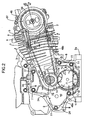
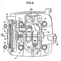
- an engine main body 1 of a general purpose four-cycle engine E includes: as components a crankcase 2 having on its lower part a mounting seat 2a; a cylinder block 3 connected integrally to the crankcase 2 and having an upwardly inclined cylinder bore 3a; and a cylinder head 5 joined to an upper end face of the cylinder block 3 via a gasket 4.
- Four main connecting bolts 6 disposed at four positions around the cylinder bore 3a and two auxiliary connecting bolts 7 and 7, which will be described later, are used and for joining, that is, securing the cylinder head 5 to the cylinder block 3.
- the crankcase 2 has one open side face; a plurality of steps 8, 8 are formed integrally on an inner peripheral wall slightly close to the inside relative to the open side face, the steps 8, 8 being arranged in the peripheral direction so as to face toward the open side face, and a bearing bracket 10 is secured to these steps 8, 8 via a plurality of bolts 11, 11.
- This bearing bracket 10 and another side wall of the crankcase 2 support opposite end parts of a horizontally disposed crankshaft 12 via bearings 13 and 13'.
- opposite end parts of a balancer shaft 14 disposed adjacent to and in parallel with the crankshaft 12 are similarly supported via bearings 15 and 15 by the bearing bracket 10 and said other side wall of the crankcase 2.
- a continuous reinforcing rib 16 is formed integrally with the outer periphery of the crankcase 2 so as to surround the plurality of steps 8, 8, and an end part of the reinforcing rib 16 is connected integrally to an outside wall of the cylinder block 3, which is integral with the crankcase 2.
- the reinforcing rib 16 provides, on the outer periphery of the crankcase 2, mutual connection between the plurality of steps 8, 8, which are inside the reinforcing rib 16, the rigidity with which the bearing bracket 10 is supported by these steps 8, 8 and, consequently, the rigidity with which the crankshaft 12 is supported by the bearing bracket 10, can be increased effectively. As a result, the crankcase 2 can be made thin and light. In particular, since an end part of the reinforcing rib 16 is connected integrally to the outside wall of the cylinder block 3, the reinforcing function of the reinforcing rib 16 can be enhanced, thus further increasing the rigidity with which the bearing bracket 10 is supported.
- a side cover 17 is joined to the crankcase 2 via a plurality of bolts 24 to close the open face on said one side of the crankcase 2.
- One end part of the crankshaft 12 runs through the side cover 17 and projects outward as an output shaft part, and an oil seal 18 is mounted on the side cover 17 to be in intimate contact with the outer periphery of the output shaft part.
- the other end part of the crankshaft 12 runs through said other side wall of the crankcase 2, and an oil seal 19 is mounted on said other side wall of the crankcase 2 to be in intimate contact with said other end part of the crankshaft 12 so as to be adjacent to the outside of the bearing 13'.
- a flywheel 21, which also functions as a rotor of a generator 20, is secured to said other end part of the crankshaft 12, and a cooling fan 22 is attached to an outside face of the flywheel 21.
- a recoil-type starter 23 which is supported on the crankcase 2, is disposed so as to face said other end part of the crankshaft 12.
- a piston 25 fitted into the cylinder bore 3a is connected to the crankshaft 12 via a connecting rod 26.
- a combustion chamber 27 communicating with the cylinder bore 3a, and an intake port 28i and an exhaust port 28e each opening in the combustion chamber 27 are formed in the cylinder head 5.
- An intake valve 29i and an exhaust valve 29e are mounted in the cylinder head 5 for opening and closing the ends of the intake and exhaust ports 28i and 28e respectively that open to the combustion chamber 27.
- Valve springs 30i and 30e are fitted onto the intake and exhaust valves 29i and 29e to urge these valves 29i and 29e in a direction in which they close.
- the intake and exhaust valves 29i and 29e are opened and closed by a valve operating system 35 operating in cooperation with these valve springs 30i and 30e.
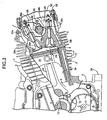
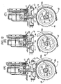
- valve operating system 35 is described by reference to FIG. 3 , FIG. 4 , and FIG. 6 to FIG. 12 .
- the valve operating system 35 comprises a camshaft 36, a timing transmission system 37, an intake rocker arm 38i, and an exhaust rocker arm 38e.
- the camshaft 36 is supported on the cylinder head 5 so as to be parallel to the crankshaft 12, and includes an intake cam 36i and an exhaust cam 36e.
- the timing transmission system 37 provides a connection between the crankshaft 12 and the camshaft 36.
- the intake rocker arm 38i provides an operative connection between the intake cam 36i and the intake valve 29i.
- the exhaust rocker arm 38e provides an operative connection between the exhaust cam 36e and the exhaust valve 29e.
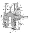
- the camshaft 36 has opposite end parts supported by a pouch-shaped bearing hole 39 and a ball bearing 41, the bearing hole 39 being formed in one side wall 5a of the cylinder head 5, and the ball bearing 41 being fitted into a bearing fitting hole 40 of a dividing wall 5b in a middle section of the cylinder head 5.
- One common rocker shaft 42 swingably supporting the intake and exhaust rocker arms 38i and 38e has opposite end parts supported by first and second support holes 43' and 43 formed in said one side wall 5a and the dividing wall 5b, respectively.
- the first support hole 43' of said one side wall 5a is pouch-shaped
- the second support 43 of the dividing wall 5b is a through hole.
- a fixing bolt 44 having its extremity abutting against the outer end of the rocker shaft 42 is screwed into the dividing wall 5b at an outer end part of the second support hole 43.
- the rocker shaft 42 is thus prevented from moving in a thrust direction by the pouch-shaped first support hole 43' and the fixing bolt 44.
- the fixing bolt 44 has on its head part an integral flange seat 44a having a relatively large diameter, the flange seat 44a abutting against an outer end face of an outer race 41 a of the ball bearing 41 supporting the camshaft 36.
- An inner race 41 b of the ball bearing 41 is press-fitted onto the camshaft 36.
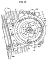
- the timing transmission system 37 comprises a toothed drive pulley 45 secured to the crankshaft 12, a toothed driven pulley 46 secured to the camshaft 36, and an endless timing belt 47 wound around the drive and driven pulleys 45 and 46, the number of teeth of the driven pulley 46 being twice of that of the drive pulley 45. Rotation of the crankshaft 12 is therefore reduced by 1/2 by this timing transmission system 37, and transmitted to the camshaft 36. Due to rotation of the camshaft 36, the intake and exhaust cams 36i and 36e make the intake and exhaust rocker arms 38i and 38e swing against the urging forces of the valve springs 30i and 30e respectively, thereby opening and closing the intake and exhaust valves 29i and 29e.
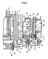
- This timing transmission system 37 is housed in a timing transmission chamber 48 formed by connecting in sequence a lower chamber 48a, a middle chamber 48b, and an upper chamber 48c, the lower chamber 48a being defined between the bearing bracket 10 and the side cover 17, the middle chamber 48b being formed in the cylinder block 3 on one side of the cylinder bore 3a, and the upper chamber 48c being formed on one side of the cylinder head 5. That is, the drive pulley 45 is disposed in the lower chamber 48a, the driven pulley 46 is disposed in the upper chamber 48c, and the timing belt 47 is disposed so as to run through the middle chamber 48b. In this way, the space between the bearing bracket 10 and the side cover 17 is utilized effectively for arranging the timing transmission system 37, thereby making the engine E compact.
- a valve operating chamber 49 having an open upper face is formed in the cylinder head 5 between said one side wall 5a and the dividing wall 5b, and the intake and exhaust cams 36i and 36e of the camshaft 36 and the intake and exhaust rocker arms 38i and 38e, etc. are housed in the valve operating chamber 49.
- the open upper face of the valve operating chamber 49 is closed by a head cover 52 joined to the cylinder head 5 via a bolt 53.
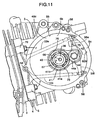
- the upper chamber 48c of the timing transmission chamber 48 and the valve operating chamber 49 communicate with each other via an oil passage hole 75 (see FIG. 8 and FIG. 11 ) provided in the dividing wall 5b and a plurality of oil passage channels 76 (see FIG. 6 and FIG. 11 ) provided on an inner peripheral face of the bearing fitting hole 40.
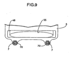
- an access window 55 is provided on an outer end face 5c of the cylinder head 5, the access window 55 opening the upper chamber 48c so that the outer side face of the driven pulley 46 faces the access window 55.
- the access window 55 is used for inserting the driven pulley 46 within the timing belt 47, and mounting the driven pulley 46 on the camshaft 36.
- a lid body 57 closing the access window 55 is joined to the outer end face 5c via a seal 56 by means of a plurality of bolts 58.
- the outer end face 5c of the cylinder head 5, to which the lid body 57 is joined comprises an inclined face 5c that is inclined so that at least part of the outer periphery of the driven pulley 46 on the side opposite to the drive pulley 45 is exposed through the access window 55, and preferably at least half the periphery of the driven pulley 46 on the side opposite to the drive pulley 45 is exposed through the access window 55.
- the driven pulley 46 comprises a bottomed cylindrical hub 46a, a web 46b that widens radially from the hub 46a, and a toothed rim 46c formed on the outer periphery of the web 46b.
- the hub 46a is fitted onto the outer periphery of an outer end part of the camshaft 36 projecting toward the upper chamber 48c side.
- An end wall of the hub 46a is provided with a bolt hole 60 positioned eccentrically to the center of the hub 46a, and a positioning groove 61 extending from one side of the bolt hole 60 to the side exactly opposite to the direction of the eccentricity.
- a first match mark 62a is cut into an outer side face of the rim 46c, and a second match mark 62b corresponding to the first match mark 62a is cut into the outer end face 5c of the cylinder head 5.
- the web 46b is provided with a plurality of through holes 64, 64 that penetrate it.
- the outer end part of the camshaft 36 is provided, as shown in FIG. 6 and FIG. 11 , with a threaded hole 66 corresponding to the bolt hole 60 and a positioning pin 67 corresponding to the positioning groove 61.
- the crankshaft 12 When the crankshaft 12 is at a predetermined rotational position corresponding to a specified position (for example, top dead center) of the piston 25, and the camshaft 36 is at a position in a predetermined phase relationship with respect to the crankshaft 12, the first match mark 62a and the second match mark 62b, the bolt hole 60 and the threaded hole 66, and the positioning groove 61 and the positioning pin 67 each coincide with each other on a straight line L running through the centers of the two shafts 12 and 36.
- the crankshaft 12 is first fixed at the rotational position corresponding to the specified position of the piston 25. Subsequently, as shown in FIG. 12(A) , the driven pulley 46 is put inside the timing belt 47, which has been wound around the drive pulley 45 in advance, while making the first match mark 62a of the rim 46c match the second match mark 62b of the cylinder head 5. Next, as shown in FIG. 12(A)
- the timing transmission system 37 is mounted on the crankshaft 12 and the camshaft 36, which are mounted on the crankcase 2 and the cylinder head 5 in advance, in the predetermined phase relationship.
- the outer end face of the cylinder head 5 on which the access window 55 opens is the inclined face 5c, and part of the outer periphery of the driven pulley 46 is exposed through the access window 55, the part of the driven pulley 46 exposed outside the access window 55 can easily be held by a tool, etc. without interference by the cylinder head 5, thereby facilitating the mounting of the driven pulley 46 on the camshaft 36 and the removal thereof. Therefore, this contributes to an improvement in the assemblability and the ease of maintenance.
- a head part of the engine main body 1 is shaped such that its lateral width narrows toward the extremity side, thus making the engine E compact.
- a pair of projecting parts 70 and 70 projecting outwardly of the access window 55 beneath the access window 55 are formed on the cylinder head 5; these projecting parts 70 and 70 are superimposed on an upper end face, on the outside of the middle chamber 48b, of the cylinder block 3 via the gasket 4, and secured to the cylinder block 3 via the auxiliary connecting bolts 7 and 7.
- auxiliary connecting bolts 7 and 7 it is possible to adequately increase the surface pressure acting on the gasket 4 from the cylinder block 3 and the cylinder head 5 even outside the middle chamber 48b housing the timing belt 47. Moreover, since the presence of the inclined face 5c secures a sufficient space above the auxiliary connecting bolts 7 and 7, for receiving a tool for operating the auxiliary connecting bolts 7 and 7, tightening of the auxiliary connecting bolts 7 and 7 can easily be carried out. This means that the extent to which the projecting parts 70 and 70 project outwardly of the access window 55 can be made small; and this also contributes to making the engine E compact.
- Tightening the auxiliary connecting bolts 7 and 7 is carried out prior to the lid body 57 being mounted.
- the lower chamber 48a of the timing transmission chamber 48 communicates with the interior of the crankcase 2, that is, the crank chamber 9, through the plurality of steps 8, 8 on the inner wall of the crankcase 2 supporting the bearing bracket 10, and a predetermined amount of lubricating oil 71 that is common to the crank chamber 9 and the lower chamber 48a accumulates in these chambers.
- an impeller type oil slinger 72 is disposed in the lower chamber 48a so that part of the oil slinger 72 is submerged in the oil 71 that accumulates in the lower chamber 48a.
- the oil slinger 72 is driven by the crankshaft 12 via gears 74 and 74'.
- This oil slinger 72 scatters the oil 71 around by its rotation, and an oil guide wall 73 for guiding the scattered oil to the timing belt 47 side is formed integrally with an outer side face of the bearing bracket 10 so as to surround the oil slinger 72 and the periphery of the timing belt 47 on the drive pulley 45 side. Since the bearing bracket 10 is a relatively small component, this can easily be cast together with the oil guide wall 73. Further, since the bearing bracket 10 integrally has the oil guide wall 73, its rigidity is strengthened and this is also effective in enhancing the rigidity with which the crankshaft 12 is supported.
- oil scattered by the oil slinger 72 is guided by the oil guide wall 73 to the timing belt 47 side; the oil that has been deposited on the timing belt 47 is transferred to the upper chamber 48c by the belt 47; scattered around by being shaken off due to centrifugal force when the timing belt 47 becomes wound around the driven pulley 46; and made to collide with the surrounding wall to thus form an oil mist; and the upper chamber 48c is filled with this oil mist, thereby lubricating not only the entire timing transmission system 37 but also the ball bearing 41 of the camshaft 36.
- a base part of the valve operating chamber 49 communicates with the crank chamber 9 via a series of oil return passages 77 formed in the cylinder head 5 and the cylinder block 3 along one side of the cylinder bore 3a.
- the oil return passage 77 is inclined downward toward the crank chamber 9 so that oil flows down from the valve operating chamber 49 to the crank chamber 9.
- the belt type timing transmission system 37 may be replaced with a chain type.
Landscapes
- Engineering & Computer Science (AREA)
- Mechanical Engineering (AREA)
- General Engineering & Computer Science (AREA)
- Chemical & Material Sciences (AREA)
- Combustion & Propulsion (AREA)
- Valve-Gear Or Valve Arrangements (AREA)
- Cylinder Crankcases Of Internal Combustion Engines (AREA)
- Valve Device For Special Equipments (AREA)
Claims (3)
- Motorventilantriebssystem, worin eine Nockenwelle (36) über ein Lager (41) an einem Zylinderkopf (5) gelagert ist, in dem ein Einlassventil (29i) und ein Auslassventil (29e) vorgesehen sind, und ein Einlasskipphebel (38i) und ein Auslasskipphebel (38e) an einer an dem Zylinderkopf (5) parallel zur Nockenwelle (36) gelagerten Kipphebelwelle (42) angebracht sind, wobei der Einlasskipphebel (38i) und der Auslasskipphebel (38e) jeweils eine Verbindung zwischen der Nockenwelle (36) und dem Einlassventil (29i) sowie zwischen der Nockenwelle (36) und dem Auslassventil (29e) vorsehen,
worin ein Befestigungselement (44), das sich gegen ein Endteil der Kipphebelwelle (42) abstützt, um deren Bewegung in Schubrichtung zu begrenzen, an dem Zylinderkopf (5) gesichert ist, und ein Begrenzungsabschnitt (44a), der sich gegen eine Seitenfläche des Lagers (41) abstützt, um dessen Bewegung in Schubrichtung zu begrenzen, einstückig mit dem Befestigungselement (44) ausgebildet ist,
dadurch gekennzeichnet, dass das Befestigungselement ein in den Zylinderkopf (5) geschraubter Befestigungsbolzen (44) ist und der Begrenzungsabschnitt einen an einem Kopfteil des Befestigungsbolzens (44) ausgebildeten Flanschsitz (44a) aufweist. - Das Motorventilantriebssystem nach Anspruch 1, worin ein Endteil der Kipphebelwelle (42) an einem in dem Zylinderkopf (5) ausgebildeten taschenförmigen ersten Lagerloch (43') gelagert ist, und das andere Endteil der Kipphebelwelle (42) an einem in dem Zylinderkopf (5) ausgebildeten durchgangslochförmigen zweiten Lagerloch (43) gelagert ist, und der Befestigungsbolzen (44) in das äußere Endteil des zweiten Lagerlochs (43) geschraubt ist.
- Das Motorventilantriebssystem nach Anspruch 1, worin ein Endteil der Nockenwelle (36) an einem in dem Zylinderkopf (5) ausgebildeten taschenförmigen Lagerloch (39) gelagert ist, und das andere Endteil der Nockenwelle (36) über das Lager(41)an dem Zylinderkopf (5) gelagert ist, und sich der Flanschsitz (44a) gegen eine äußere Seitenfläche des Lagers (41) abstützt.
Applications Claiming Priority (2)
| Application Number | Priority Date | Filing Date | Title |
|---|---|---|---|
| JP2005183606A JP4382010B2 (ja) | 2005-06-23 | 2005-06-23 | エンジンの動弁装置 |
| PCT/JP2006/312286 WO2006137379A1 (ja) | 2005-06-23 | 2006-06-20 | エンジンの動弁装置 |
Publications (3)
| Publication Number | Publication Date |
|---|---|
| EP1895112A1 EP1895112A1 (de) | 2008-03-05 |
| EP1895112A4 EP1895112A4 (de) | 2011-02-23 |
| EP1895112B1 true EP1895112B1 (de) | 2012-02-29 |
Family
ID=37570408
Family Applications (1)
| Application Number | Title | Priority Date | Filing Date |
|---|---|---|---|
| EP06766947A Not-in-force EP1895112B1 (de) | 2005-06-23 | 2006-06-20 | Ventiltrieb eines motors |
Country Status (15)
| Country | Link |
|---|---|
| US (1) | US7878165B2 (de) |
| EP (1) | EP1895112B1 (de) |
| JP (1) | JP4382010B2 (de) |
| KR (1) | KR100947517B1 (de) |
| CN (1) | CN100564814C (de) |
| AR (1) | AR054145A1 (de) |
| AU (1) | AU2006260302B2 (de) |
| BR (1) | BRPI0611994A2 (de) |
| CA (1) | CA2611611C (de) |
| ES (1) | ES2380572T3 (de) |
| MY (1) | MY143511A (de) |
| PA (1) | PA8682501A1 (de) |
| PE (1) | PE20070131A1 (de) |
| TW (1) | TWI315366B (de) |
| WO (1) | WO2006137379A1 (de) |
Families Citing this family (6)
| Publication number | Priority date | Publication date | Assignee | Title |
|---|---|---|---|---|
| CN100434657C (zh) * | 2006-10-28 | 2008-11-19 | 无锡开普动力有限公司 | 四冲程顶置凸轮式发动机 |
| DE102009009665A1 (de) * | 2009-02-19 | 2010-08-26 | Mahle International Gmbh | Brennkraftmaschine mit wenigstens einer Nockenwelle |
| JP5391381B2 (ja) * | 2010-04-12 | 2014-01-15 | 和子 杉田 | 圧縮空気往復機関 |
| JP5538082B2 (ja) | 2010-06-17 | 2014-07-02 | 株式会社マキタ | 4サイクルエンジン及びこれを用いた作業機 |
| JP6105410B2 (ja) * | 2013-06-28 | 2017-03-29 | ヤマハ発動機株式会社 | エンジン |
| DE102014201247A1 (de) * | 2014-01-23 | 2015-07-23 | Schaeffler Technologies AG & Co. KG | Trägermodul für einen Ventiltrieb einer Brennkraftmaschine |
Family Cites Families (19)
| Publication number | Priority date | Publication date | Assignee | Title |
|---|---|---|---|---|
| JPS5666003U (de) * | 1979-10-25 | 1981-06-02 | ||
| JPS5951723B2 (ja) | 1979-10-31 | 1984-12-15 | 日本電信電話株式会社 | サ−ミスタ |
| JPS5670103U (de) * | 1979-11-01 | 1981-06-10 | ||
| US4295492A (en) | 1979-11-13 | 1981-10-20 | Greer Hydraulics, Incorporated | Low cost accumulator device |
| JPS5818004A (ja) | 1981-07-24 | 1983-02-02 | 株式会社荏原製作所 | ボイラ系における缶水濃縮度計測装置 |
| JPS5818004U (ja) * | 1981-07-29 | 1983-02-03 | マツダ株式会社 | エンジンのカムシヤフト保持装置 |
| JPS5877101U (ja) | 1981-11-20 | 1983-05-25 | マツダ株式会社 | エンジンのカムシヤフトスラスト受け装置 |
| JPS58173888A (ja) * | 1982-04-05 | 1983-10-12 | 松下電工株式会社 | プリント配線板のスルホ−ル接続法 |
| JPS5945202U (ja) | 1982-09-18 | 1984-03-26 | 本田技研工業株式会社 | カム軸取付装置 |
| JPS59135308A (ja) * | 1983-01-21 | 1984-08-03 | Canon Inc | 距離測定装置 |
| JPS59135308U (ja) | 1983-03-02 | 1984-09-10 | 三菱自動車工業株式会社 | カム軸支持構造 |
| JPH0714103U (ja) | 1993-08-06 | 1995-03-10 | 株式会社クボタ | 頭上カム式エンジンの動弁装置 |
| JP3333667B2 (ja) * | 1995-08-09 | 2002-10-15 | 本田技研工業株式会社 | Sohc型エンジンの動弁装置 |
| JP3369036B2 (ja) | 1995-12-26 | 2003-01-20 | ヤマハ発動機株式会社 | 頭上カム式エンジン |
| JP2913273B2 (ja) * | 1996-04-17 | 1999-06-28 | 本田技研工業株式会社 | エンジンの回転検出装置 |
| JP3526836B2 (ja) * | 2001-09-14 | 2004-05-17 | 本田技研工業株式会社 | 内燃機関の動弁装置におけるロッカアームシャフトの回り止め装置 |
| JP3966778B2 (ja) * | 2002-07-03 | 2007-08-29 | 本田技研工業株式会社 | エンジンにおける組付け用開口部閉塞構造 |
| JP4025667B2 (ja) * | 2003-03-18 | 2007-12-26 | 本田技研工業株式会社 | 頭上カム型エンジン |
| JP4052964B2 (ja) * | 2003-03-19 | 2008-02-27 | 本田技研工業株式会社 | ロッカーアーム軸の回り止め装置 |
-
2005
- 2005-06-23 JP JP2005183606A patent/JP4382010B2/ja not_active Expired - Fee Related
-
2006
- 2006-05-25 TW TW095118586A patent/TWI315366B/zh not_active IP Right Cessation
- 2006-06-15 MY MYPI20062830A patent/MY143511A/en unknown
- 2006-06-20 BR BRPI0611994-8A patent/BRPI0611994A2/pt not_active IP Right Cessation
- 2006-06-20 AU AU2006260302A patent/AU2006260302B2/en not_active Ceased
- 2006-06-20 ES ES06766947T patent/ES2380572T3/es active Active
- 2006-06-20 CN CNB2006800223840A patent/CN100564814C/zh not_active Expired - Fee Related
- 2006-06-20 US US11/921,016 patent/US7878165B2/en active Active
- 2006-06-20 EP EP06766947A patent/EP1895112B1/de not_active Not-in-force
- 2006-06-20 KR KR1020077029897A patent/KR100947517B1/ko not_active Expired - Fee Related
- 2006-06-20 CA CA2611611A patent/CA2611611C/en not_active Expired - Fee Related
- 2006-06-20 WO PCT/JP2006/312286 patent/WO2006137379A1/ja not_active Ceased
- 2006-06-21 PE PE2006000704A patent/PE20070131A1/es not_active Application Discontinuation
- 2006-06-22 AR ARP060102676A patent/AR054145A1/es active IP Right Grant
- 2006-06-23 PA PA20068682501A patent/PA8682501A1/es unknown
Also Published As
| Publication number | Publication date |
|---|---|
| AR054145A1 (es) | 2007-06-06 |
| US7878165B2 (en) | 2011-02-01 |
| AU2006260302A1 (en) | 2006-12-28 |
| MY143511A (en) | 2011-05-31 |
| CA2611611C (en) | 2010-09-21 |
| CA2611611A1 (en) | 2006-12-28 |
| TW200704870A (en) | 2007-02-01 |
| ES2380572T3 (es) | 2012-05-16 |
| CN100564814C (zh) | 2009-12-02 |
| EP1895112A4 (de) | 2011-02-23 |
| JP2007002749A (ja) | 2007-01-11 |
| AU2006260302B2 (en) | 2010-04-08 |
| PA8682501A1 (es) | 2007-01-17 |
| JP4382010B2 (ja) | 2009-12-09 |
| KR20080014882A (ko) | 2008-02-14 |
| US20090020083A1 (en) | 2009-01-22 |
| BRPI0611994A2 (pt) | 2010-10-13 |
| PE20070131A1 (es) | 2007-02-09 |
| WO2006137379A1 (ja) | 2006-12-28 |
| TWI315366B (en) | 2009-10-01 |
| EP1895112A1 (de) | 2008-03-05 |
| CN101203661A (zh) | 2008-06-18 |
| KR100947517B1 (ko) | 2010-03-12 |
Similar Documents
| Publication | Publication Date | Title |
|---|---|---|
| EP1895117B1 (de) | Ventiltrieb eines motors | |
| EP1895112B1 (de) | Ventiltrieb eines motors | |
| GB2230560A (en) | Engine cylinder head idler mounting housing | |
| US8430076B2 (en) | Engine | |
| EP1895135B1 (de) | Motor | |
| JP4283251B2 (ja) | エンジン | |
| JP3327322B2 (ja) | バルブタイミング可変装置を備えた4サイクルエンジン | |
| JP4319170B2 (ja) | エンジンの動弁装置 | |
| JP2507673Y2 (ja) | エンジンのカムシャフト支持装置 | |
| JPS62284913A (ja) | 内燃エンジン用カムスプロケツトの潤滑構造 |
Legal Events
| Date | Code | Title | Description |
|---|---|---|---|
| PUAI | Public reference made under article 153(3) epc to a published international application that has entered the european phase |
Free format text: ORIGINAL CODE: 0009012 |
|
| 17P | Request for examination filed |
Effective date: 20071122 |
|
| AK | Designated contracting states |
Kind code of ref document: A1 Designated state(s): DE ES FR GB IT SE |
|
| DAX | Request for extension of the european patent (deleted) | ||
| RBV | Designated contracting states (corrected) |
Designated state(s): DE ES FR GB IT SE |
|
| DAX | Request for extension of the european patent (deleted) | ||
| A4 | Supplementary search report drawn up and despatched |
Effective date: 20110121 |
|
| RIC1 | Information provided on ipc code assigned before grant |
Ipc: F01L 1/46 20060101ALI20110117BHEP Ipc: F01L 1/053 20060101ALI20110117BHEP Ipc: F02F 1/24 20060101ALI20110117BHEP Ipc: F01L 1/04 20060101ALI20110117BHEP Ipc: F01L 1/18 20060101AFI20070220BHEP |
|
| 17Q | First examination report despatched |
Effective date: 20110210 |
|
| RIC1 | Information provided on ipc code assigned before grant |
Ipc: F01L 1/46 20060101ALI20110628BHEP Ipc: F01L 1/04 20060101ALI20110628BHEP Ipc: F01L 1/18 20060101AFI20110628BHEP Ipc: F01L 1/053 20060101ALI20110628BHEP Ipc: F02F 1/24 20060101ALI20110628BHEP |
|
| GRAP | Despatch of communication of intention to grant a patent |
Free format text: ORIGINAL CODE: EPIDOSNIGR1 |
|
| GRAS | Grant fee paid |
Free format text: ORIGINAL CODE: EPIDOSNIGR3 |
|
| RAP1 | Party data changed (applicant data changed or rights of an application transferred) |
Owner name: HONDA MOTOR CO., LTD. |
|
| GRAA | (expected) grant |
Free format text: ORIGINAL CODE: 0009210 |
|
| RTI1 | Title (correction) |
Free format text: ENGINE VALVE OPERATING SYSTEM |
|
| AK | Designated contracting states |
Kind code of ref document: B1 Designated state(s): DE ES FR GB IT SE |
|
| REG | Reference to a national code |
Ref country code: GB Ref legal event code: FG4D |
|
| REG | Reference to a national code |
Ref country code: DE Ref legal event code: R096 Ref document number: 602006027939 Country of ref document: DE Effective date: 20120426 |
|
| REG | Reference to a national code |
Ref country code: ES Ref legal event code: FG2A Ref document number: 2380572 Country of ref document: ES Kind code of ref document: T3 Effective date: 20120516 |
|
| REG | Reference to a national code |
Ref country code: SE Ref legal event code: TRGR |
|
| PLBE | No opposition filed within time limit |
Free format text: ORIGINAL CODE: 0009261 |
|
| STAA | Information on the status of an ep patent application or granted ep patent |
Free format text: STATUS: NO OPPOSITION FILED WITHIN TIME LIMIT |
|
| 26N | No opposition filed |
Effective date: 20121130 |
|
| REG | Reference to a national code |
Ref country code: DE Ref legal event code: R097 Ref document number: 602006027939 Country of ref document: DE Effective date: 20121130 |
|
| REG | Reference to a national code |
Ref country code: FR Ref legal event code: PLFP Year of fee payment: 11 |
|
| REG | Reference to a national code |
Ref country code: FR Ref legal event code: PLFP Year of fee payment: 12 |
|
| REG | Reference to a national code |
Ref country code: FR Ref legal event code: PLFP Year of fee payment: 13 |
|
| PGFP | Annual fee paid to national office [announced via postgrant information from national office to epo] |
Ref country code: ES Payment date: 20190603 Year of fee payment: 16 |
|
| PGFP | Annual fee paid to national office [announced via postgrant information from national office to epo] |
Ref country code: FR Payment date: 20190510 Year of fee payment: 14 |
|
| PGFP | Annual fee paid to national office [announced via postgrant information from national office to epo] |
Ref country code: GB Payment date: 20190619 Year of fee payment: 14 |
|
| REG | Reference to a national code |
Ref country code: DE Ref legal event code: R084 Ref document number: 602006027939 Country of ref document: DE |
|
| REG | Reference to a national code |
Ref country code: GB Ref legal event code: 746 Effective date: 20191217 |
|
| GBPC | Gb: european patent ceased through non-payment of renewal fee |
Effective date: 20200620 |
|
| PG25 | Lapsed in a contracting state [announced via postgrant information from national office to epo] |
Ref country code: FR Free format text: LAPSE BECAUSE OF NON-PAYMENT OF DUE FEES Effective date: 20200630 Ref country code: GB Free format text: LAPSE BECAUSE OF NON-PAYMENT OF DUE FEES Effective date: 20200620 |
|
| PGFP | Annual fee paid to national office [announced via postgrant information from national office to epo] |
Ref country code: SE Payment date: 20210610 Year of fee payment: 16 |
|
| PG25 | Lapsed in a contracting state [announced via postgrant information from national office to epo] |
Ref country code: IT Free format text: LAPSE BECAUSE OF NON-PAYMENT OF DUE FEES Effective date: 20200620 |
|
| REG | Reference to a national code |
Ref country code: ES Ref legal event code: FD2A Effective date: 20211105 |
|
| PG25 | Lapsed in a contracting state [announced via postgrant information from national office to epo] |
Ref country code: ES Free format text: LAPSE BECAUSE OF NON-PAYMENT OF DUE FEES Effective date: 20200621 |
|
| REG | Reference to a national code |
Ref country code: SE Ref legal event code: EUG |
|
| PG25 | Lapsed in a contracting state [announced via postgrant information from national office to epo] |
Ref country code: SE Free format text: LAPSE BECAUSE OF NON-PAYMENT OF DUE FEES Effective date: 20220621 |
|
| PGFP | Annual fee paid to national office [announced via postgrant information from national office to epo] |
Ref country code: DE Payment date: 20230425 Year of fee payment: 18 |
|
| REG | Reference to a national code |
Ref country code: DE Ref legal event code: R119 Ref document number: 602006027939 Country of ref document: DE |
|
| PG25 | Lapsed in a contracting state [announced via postgrant information from national office to epo] |
Ref country code: DE Free format text: LAPSE BECAUSE OF NON-PAYMENT OF DUE FEES Effective date: 20250101 |