EP1894677A2 - Schnurloses kraftgetriebenes Werkzeug - Google Patents
Schnurloses kraftgetriebenes Werkzeug Download PDFInfo
- Publication number
- EP1894677A2 EP1894677A2 EP07016945A EP07016945A EP1894677A2 EP 1894677 A2 EP1894677 A2 EP 1894677A2 EP 07016945 A EP07016945 A EP 07016945A EP 07016945 A EP07016945 A EP 07016945A EP 1894677 A2 EP1894677 A2 EP 1894677A2
- Authority
- EP
- European Patent Office
- Prior art keywords
- screw tightening
- power tool
- unit
- operations
- completion
- Prior art date
- Legal status (The legal status is an assumption and is not a legal conclusion. Google has not performed a legal analysis and makes no representation as to the accuracy of the status listed.)
- Granted
Links
- 238000012544 monitoring process Methods 0.000 claims abstract description 12
- 238000001514 detection method Methods 0.000 claims abstract description 8
- 229920001971 elastomer Polymers 0.000 claims description 10
- 239000000806 elastomer Substances 0.000 claims description 10
- 230000008859 change Effects 0.000 description 9
- 238000003825 pressing Methods 0.000 description 5
- 238000010586 diagram Methods 0.000 description 4
- 238000000034 method Methods 0.000 description 3
- 239000011295 pitch Substances 0.000 description 3
- 238000003860 storage Methods 0.000 description 3
- 230000003213 activating effect Effects 0.000 description 2
- 206010027175 memory impairment Diseases 0.000 description 2
- 230000002265 prevention Effects 0.000 description 2
- 230000008569 process Effects 0.000 description 2
- 239000011347 resin Substances 0.000 description 2
- 229920005989 resin Polymers 0.000 description 2
- 238000005452 bending Methods 0.000 description 1
- 238000010276 construction Methods 0.000 description 1
- 230000002950 deficient Effects 0.000 description 1
- 230000006866 deterioration Effects 0.000 description 1
- 238000001746 injection moulding Methods 0.000 description 1
- 238000012423 maintenance Methods 0.000 description 1
- 238000004519 manufacturing process Methods 0.000 description 1
- 230000007246 mechanism Effects 0.000 description 1
- 230000004048 modification Effects 0.000 description 1
- 238000012986 modification Methods 0.000 description 1
- 238000000465 moulding Methods 0.000 description 1
- 239000002699 waste material Substances 0.000 description 1
Images


Classifications
-
- B—PERFORMING OPERATIONS; TRANSPORTING
- B25—HAND TOOLS; PORTABLE POWER-DRIVEN TOOLS; MANIPULATORS
- B25B—TOOLS OR BENCH DEVICES NOT OTHERWISE PROVIDED FOR, FOR FASTENING, CONNECTING, DISENGAGING OR HOLDING
- B25B21/00—Portable power-driven screw or nut setting or loosening tools; Attachments for drilling apparatus serving the same purpose
- B25B21/002—Portable power-driven screw or nut setting or loosening tools; Attachments for drilling apparatus serving the same purpose for special purposes
-
- B—PERFORMING OPERATIONS; TRANSPORTING
- B25—HAND TOOLS; PORTABLE POWER-DRIVEN TOOLS; MANIPULATORS
- B25F—COMBINATION OR MULTI-PURPOSE TOOLS NOT OTHERWISE PROVIDED FOR; DETAILS OR COMPONENTS OF PORTABLE POWER-DRIVEN TOOLS NOT PARTICULARLY RELATED TO THE OPERATIONS PERFORMED AND NOT OTHERWISE PROVIDED FOR
- B25F5/00—Details or components of portable power-driven tools not particularly related to the operations performed and not otherwise provided for
- B25F5/006—Vibration damping means
-
- B—PERFORMING OPERATIONS; TRANSPORTING
- B25—HAND TOOLS; PORTABLE POWER-DRIVEN TOOLS; MANIPULATORS
- B25F—COMBINATION OR MULTI-PURPOSE TOOLS NOT OTHERWISE PROVIDED FOR; DETAILS OR COMPONENTS OF PORTABLE POWER-DRIVEN TOOLS NOT PARTICULARLY RELATED TO THE OPERATIONS PERFORMED AND NOT OTHERWISE PROVIDED FOR
- B25F5/00—Details or components of portable power-driven tools not particularly related to the operations performed and not otherwise provided for
- B25F5/02—Construction of casings, bodies or handles
Definitions
- the present invention relates to a rechargeable power tool having a function of monitoring a screw tightening operation.
- the present inventors have proposed an idea of accommodating a control circuit in a main body of the power tool, for monitoring the screw tightening operations.
- the control circuit is a precision electronic device so that the control circuit needs to be protected from impacts and vibrations. Accordingly, when a control circuit board is installed inside the power tool, a location of the board needs to be carefully chosen. Especially, when the power tool falls and collides against the ground, great impacts and vibrations may be given to the control circuit to be damaged. Therefore, it is critical to protect it from damage.
- the present invention provides a power tool capable of performing management of the number of tightening operations without using a power cord that is unnecessary for a rechargeable power tool.
- the cordlessness can be fully utilized and a work area can not be restricted, so that work efficiency can be enhanced.
- the power tool can be a small size for convenient use and can have good durability for being used under severe conditions.
- a power tool including: a driving unit for performing screw tightening operations; a motor for rotatably driving the driving unit; a rechargeable battery pack; a trigger switch for turning on and off the motor; and a control circuit, accommodated in a main body of the power tool, for monitoring the screw tightening operations.
- the control circuit has a screw tightening completion detection unit for detecting completion of a screw tightening operation; a screw tightening count unit for counting the number of detected tightening operations; a screw tightening number setting unit for presetting the number of screws to be tightened; and a screw tightening completion notifying unit for notifying completion of the screw tightening operations when the number of detected tightening operations reaches the preset number of screws.
- the screw tightening number setting unit and the screw tightening completion notifying unit are disposed at a lower front portion of a grip portion, in the main body of the power tool, for being held by a hand.
- the power tool can performs management of the number of tightening operations without a power cord that is unnecessary for a rechargeable power tool by using the control circuit accommodated in the main body of the power tool, for monitoring a screw tightening operation.
- the lower front portion of the grip portion is provided with a screw tightening number setting unit and a screw tightening completion notifying unit so that the grip portion of the housing need not to be enlarged and, also, gripping of the grip portion is not hindered.
- the grip portion is not subject to great impacts or vibrations, compared to the heavy body portion having therein the motor, when the power tool is dropped during its use. Therefore, it is possible to effectively prevent damages from being inflicted on the components of the screw tightening number setting unit and the screw tightening completion notifying unit.
- a protruded elastomer is installed around an outer periphery of the lower front portion of the grip portion.
- the elastomer is designed to absorb the impacts when the power tool main body is dropped during its use. Accordingly, the grip portion is protected from large impacts or vibrations and, it is also possible to prevent the breakage of the screw tightening number setting unit and its components (the setting/display unit, the piezoelectric buzzer and the control circuit). Further, the durability of the power tool can be further enhanced with the addition of the elastomer so that the power tool can be used under severe conditions.
- the screw tightening number setting unit may be provided with a hold function to prevent the preset number of screws to be fastened from being changed.
- the hold function when the hold function is activated, the preset number of screws may not be changed accidentally. For instance, even if the screw tightening number setting unit is manipulated unintentionally during the operation, the preset number of screws is unchanged. Consequently, the preset number of screws can be precisely managed while maintaining the setting state during the operation.
- a body portion and the grip portion of the main body of the power tool are connected rotatably such that an angle therebetween is changed freely and the display of the number of tightening operations set by the screw tightening number setting unit provided at the lower front portion of the grip portion is displayed upside down.
- the operator when an operator use the power tool by holding the grip portion heading either upward or downward, it is easy for the operator to read data on the setting/display unit and perform a smooth screw tightening operations.
- the power tool can performs management of the number of tightening operations without a power cord that is unnecessary for a rechargeable power tool, by using the control circuit accommodated in the main body of the power tool, for monitoring a screw tightening operation. Further, a work area can not be restricted, so that work efficiency can be enhanced.
- the lower front portion of the grip portion is provided with a screw tightening number setting unit and a screw tightening completion notifying unit so that the gripping of the grip portion is not hindered and the power tool can be also conveniently used in a small space due to its small size. Further, the grip portion is not subject to great impacts or vibrations, compared to the heavy body portion having therein the motor, when the power tool is dropped during its use. Therefore, it is possible to effectively prevent damages from being inflicted on the components of the screw tightening number setting unit and the screw tightening completion notifying unit so that the durability of the power tool can be further enhanced and the power tool can be used under severe conditions.
- an electric screwdriver will be described as an example of a power tool 1.
- the power tool 1 can be a cordless hammer drill, a cordless drill/driver, or any other device obvious to one skilled in the art, without departing from the scope of the present invention.
- the power tool 1 includes a driving unit 24 for performing screw tightening operations; a motor 11 for rotatably driving the driving unit 24; a trigger switch SW for turning on and off the motor 11; an attachable/detachable rechargeable battery pack 9; and a housing 3 for accommodating therein the above components.
- the driving unit 24 is provided with a clutch mechanism. As the screw tightening operation proceeds, a torque applied to a driver bit pressed against a screw to be tightened increases and reaches a specific level. At that moment, the clutch is driven to disengage a mechanical connection between the motor 11 and the corresponding driver bit.
- a screw tightening completion detection unit 4 detects that and transmits a shut-off signal (pulse signal) to a screw tightening count unit 5.
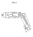
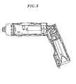
- the housing 3 of a power tool main body 2 can have a straight shape (T-shape) or an L-shape configuration for the balance of the main body 2.
- a grip portion 12 and a body portion 13 are connected rotatably about a rotational shaft portion 14 such that an angle therebetween can be changed freely.
- the rotational shaft 14 allows the housing 3 of the main body 2 to be varied between the straight shape and the L-shape.
- a structure for changing the angle about the rotational shaft portion 14 and maintaining changed angle can be configured properly without being limited to a specific one.
- the shape of the housing 3 can be varied to provide an easy grip for an operator.
- the L-shaped housing 3 is suitable for a horizontal or an upward screw tightening operation
- the straight-shaped housing 3 is suitable for a downward screw tightening operation.
- the body portion 13 of the housing 3 has the driving unit 24, the motor 11, the trigger switch SW, a lock switch 15 for maintaining the off state of the trigger switch SW, and a control switch 16 for adjusting an output torque and a rotation speed of the motor 11.
- Installed at the clutch side of the motor 11 is a photo-interrupter 4a constituting the screw tightening completion detection unit 4.
- the screw tightening completion detection unit 4 is not limited to employing the photo-interrupter 4a for detecting the completion of the screw tightening but may also employ a distance sensor or use a motor off signal.
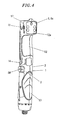
- the grip portion 12 of the housing 3 is provided with a battery pack mounting portion 17 for detachably mounting the battery pack 9. Further, a control circuit board 8a for monitoring the screw tightening operations is installed in the grip portion 12. Moreover, as illustrated in Fig. 5, a microcomputer 5a constituting the screw tightening count unit 5 is installed inside the grip portion 12 near the rotational shaft portion 14. The microcomputer 5a may also be installed inside a lower front portion 12a of the grip portion 12.
- the lower front portion 12a of the grip portion 12 is provided with a setting/display unit 6a constituting a screw tightening number setting unit 6; and a piezoelectric buzzer 7a constituting a screw tightening completion notifying unit 7.
- the lower front portion 12a of the grip portion 12 is protruded more forward in a front direction F compared to a hand-grip portion of the grip portion 12, so that the lower front portion 12a is not touched by a hand when the grip portion 12 is held by the hand. Accordingly, an operator can easily hold the grip portion 12 without touching the setting/display unit 6a that is exposed at the lower front portion 12a.
- the lower front portion 12a of the grip portion 12 indicates a portion positioned below the hand-grip portion of the grip portion 12, while facing forward along the front direction F when the grip portion 12 is held by a hand.
- the front direction F is the same as that along which an output side (driven bit) of the body portion 13 directs when the body portion 13 and the grip portion 12 form the L-shape by bending.
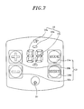
- the setting/display unit 6a exposed at the lower front portion 12a of the grip portion 12, includes a display part 18 and setting buttons 19.
- the display portion 18 has an LED part 18a for displaying numerical values and an upper and a lower lamp 18b and 18c for indicating selected count-up and count-down mode, respectively.
- the setting buttons 19 have a "mode” button 19a, a "reset” button 19d, a "+” button 19b and a "-” button 19c.
- a reference numeral 20 in Fig. 7 represents an LED light for supporting an operation in the dark environment.
- a count-up/down selection mode is executed in which one of the upper lamp 18b and the lower lamp 18c blinks. If the upper lamp 18b blinks by pressing the "+” button 19b, the count-up mode is selected. On the other hand, if the lower lamp 18c blinks by pressing the "-" button 19c, the count-down mode is selected.
- the selected mode is stored, and a setting value change mode is executed in which the LED part 18a blinks.
- the number of tightening operations can be set by pressing the "+” button 19b or the "-" button 19c. In this example, the number of tightening operations can be set up to 99.
- the setting value is stored. An order of executing the count up/down selection mode and the setting value change mode can be changed.
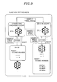
- a sound setting mode illustrated in Fig. 9 is initiated and in this example, "F1" is displayed on the LED part 18a.
- the "+" button 19b or the "-” button 19c is pressed once, one of alarm sounds having different pitches (in this example, alarm sounds having three different frequencies) is produced one after another.
- the "mode” button 19a is pressed while one of the alarm sounds having a specific pitch is produced, the alarm sound having that pitch is selected and stored. As a result, it is possible to prevent multiple operators working in a same area from being confused by the alarm sounds of adjacent operators.
- the "mode” button 19a is briefly pressed, the character displayed on the LED part 18a is switched from “F1" to "F2", and an erroneous count correcting mode is executed. If an erroneous count occurs due to stoppage of the motor 11 during the operation for example, the erroneous count can be corrected by pressing the "+” button 19b, the "-” button 19c and the “reset” button 19d during the state where the LED 18A displays "F2".
- a double tightening count prevention function is provided.
- the double tightening count prevention function is executed when a double tightening operation (tightening check-out operation) that tightens a same screw twice is carried out within a predetermined time period. For example, if the count time is set to one second, only a tightening operation performed not within one second after the completion of the previous one is counted, whereas a second tightening operation performed within one second is not counted.
- Fig. 10 shows a circuit diagram of a control circuit 8, formed on the control circuit board 8a, for monitoring screw tightening operations.
- a CPU 21 When the trigger switch SW is turned on, a CPU 21 is supplied with a power supply voltage.
- the CPU 21 has a power self-maintenance unit 22 for self-holding the power supplied thereto and a battery voltage measuring unit 25 for detecting the voltage of the supplied power.
- the CPU 21 receives a shut-off signal from the photo-interrupter 4a serving as the screw tightening completion detection unit 4 and a input setting signal from the setting/display unit 6a.
- Reference numerals 50, 51 and 52 in Fig. 10 indicate a circuit voltage driving device, a motor driving FET and a break FET, respectively.
- Step 1 when the trigger switch SW is turned on (Step 1), an initial process (circuit conduction and storage retrieval) is performed (Step 2).
- Step 3 the display portion 18 is turned on (Step 3) only when a battery pack output voltage (referred to as "battery voltage” hereinafter) is determined to be higher than a first threshold.
- the display portion 18 displays thereon preset data (e.g., a preset number (initial value of count value) "10" in case of the count-down mode is selected).
- the motor 11 is driven to perform the screw tightening operation (Step 4).
- the shut-off signal (pulse signal) is transmitted from the photo-interrupter 4a to the CPU 21, and the CPU 21 automatically stops the motor 11.
- the number of tightening operations i.e., "1" is counted by the screw tightening count unit 5, so that the number displayed on the display portion 18 is switched from “10 to "9” (if the count-up mode was selected, the number displayed on the display portion 18 is switched from “0" to "1").
- the alarm sound is produced from the piezoelectric buzzer 7a, thereby notifying the operator of the completion of the tightening operations and preventing the operator from forgetting to tighten all the screws.
- the number displayed on the setting/display unit 6a automatically returns to the original number (e.g., "10") (Step 5), thereby completing the corresponding screw tightening operations.
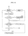
- Step 6 it is first determined whether or not the battery voltage is higher than the first threshold, as shown in Fig. 12. Only when the battery voltage is determined to be higher than the first threshold, the display portion 18 is turned on (Step 6). Next, when a new setting number is inputted, the newly inputted number is stored as a renewed number of tightening operations (Step 7). Meanwhile, if a specific period of time elapses without receiving a setting number, the power to the setting/display unit 6a is disconnected to turn off the display portion 18 (Step 8).
- the power tool main body 2 is equipped with the function of monitoring the screw tightening operations, thereby preventing an operator from forgetting to tighten all the screws. Accordingly, it is possible to avoid a defective assembly of a product and reduce an operator's burden accompanied by the potential forgetfulness of the screw tightening operation, thereby improving the accuracy and the efficiency of the screw tightening operations. Moreover, unlike in the prior art, there is no need to connect the power tool and the controller via the power cord. Especially, by providing the function of monitoring a screw tightening operation to the cordless rechargeable power tool having the attachable/detachable battery pack 9 of this example, the working area is no longer restricted. Consequently, the advantages of the cordless type can be fully utilized.
- the body portion 13 or the grip portion 12 of the housing 3 need not to be enlarged and, also, gripping of the grip portion 12 is not hindered.
- the grip portion 12 is not subject to great impacts or vibrations, compared to the heavy body portion 13 having therein the motor 11, when the power tool 1 is dropped during its use. Therefore, it is possible to effectively prevent damages from being inflicted on the components of the screw tightening number setting unit 6 and the screw tightening completion notifying unit 7.
- the power from the battery pack 9 to the setting/display unit 6a is disconnected after a specific period of time elapses after the completion of the screw tightening operations. Therefore, the waste of the battery in the battery pack 9 can be avoided. Also, when a measured battery voltage is lower than or equal to a specific value (first threshold), the power to the setting/display unit 6a is disconnected. Further, when a measured battery voltage is lower than or equal to the second threshold greater than the first threshold, the power to the motor 11 is stopped. Accordingly, power can be saved and, further, the burden on the battery pack 9 can be reduced.
- first threshold a specific value
- the setting/display unit 6a of the control circuit 8 is provided with a hold switch 10 for preventing a data change on the display portion 18, as shown in Fig. 10.
- a manipulation portion of the hold switch 10 is provided on a side surface near the setting/display unit 6a disposed at the lower front portion 12a of the grip portion 12 (see Fig. 1).
- the hold switch 10 is in a conducting state (ON)
- input to the setting/display unit 6a is allowed
- the hold switch 10 is in a non-conducting state (OFF)
- OFF non-conducting state
- the hold switch 10 By keeping the hold switch 10 to be OFF, the number of tightening operations will not change even if the setting/display unit 6a is touched accidentally during the operation. In other words, while the hold switch 10 is OFF, the change of numerals is disallowed even when the buttons of the display portion 18 are pressed.
- the number of tightening operations may be changed by accidentally touching the buttons of the setting/display unit 6a during the operation.
- the setting change during the operation can be prevented by activating the hold function of the embodiment of the present invention. As a result, the number of tightening operations can be precisely managed while maintaining the setting state.
- a circuit can be configured to cancel manipulation signals from the setting/display unit 6a when a signal for turning the motor 11 ON is inputted. Accordingly, even when the buttons of the setting/display unit 6a are accidentally pressed during the operation, the setting data or the count number will not change, as in the case of activating the hold switch 10.
- the CPU 21 in the present embodiment has a storage (not shown) for storing therein the count number or the setting data of the setting/display unit 6a. As a result, it is possible to keep a preset number of tightening operations or a last count number in the storage unit when the battery is exchanged during the screw tightening operations. Therefore, the screw tightening operations can be continued after changing the battery.
- the display of the number of tightening operations on the setting/display unit 6a provided at the lower front portion 12a of the grip portion 12 can be displayed upside down to accommodate the angle change between the straight shape and the "L" shape of the power tool 1. Accordingly, when an operator use the power tool 1 by holding the grip portion 12 heading either upward or downward, it is easy for the operator to read data on the setting/display unit 6a and perform a smooth screw tightening operations. Displaying characters or symbols upside down can be done by, e.g., pressing together the "+" button 19b and the "-” button 19c. By doing so, an embedded changeover switch is switched over, and a display control circuit allows the characters or the symbols to be displayed on the display portion upside down.
- Fig. 6 shows another embodiment of the present invention which describes an example where a protruded elastomer 30 is installed around an outer periphery of the lower front portion 12a of the grip portion 12.
- Elastomer 30 is designed to absorb the impacts when the power tool main body 2 is dropped during its use. Accordingly, the grip portion 12 is protected from large impacts or vibrations and, it is also possible to prevent the breakage of the screw tightening number setting unit 6 and its components (the setting/display unit 6a, the piezoelectric buzzer 7a and the control circuit 8).
- the durability of the power tool 1 can be further enhanced with the addition of an elastomer 30 so that the power tool 1 can be used under severe conditions.
- the power tool of the present invention can be adaptively used in various product manufacturing processes or construction sites.
- the elastomer 30 can be simply provided to the housing by 2-color injection molding of the elastomer resin and molding resin of the housing.
- the power tool of the present invention can be applied both to a cord type power tool and a rechargeable type power tool.
Applications Claiming Priority (1)
| Application Number | Priority Date | Filing Date | Title |
|---|---|---|---|
| JP2006236540A JP4669455B2 (ja) | 2006-08-31 | 2006-08-31 | 電動工具 |
Publications (3)
| Publication Number | Publication Date |
|---|---|
| EP1894677A2 true EP1894677A2 (de) | 2008-03-05 |
| EP1894677A3 EP1894677A3 (de) | 2010-08-04 |
| EP1894677B1 EP1894677B1 (de) | 2014-05-07 |
Family
ID=38814634
Family Applications (1)
| Application Number | Title | Priority Date | Filing Date |
|---|---|---|---|
| EP07016945.3A Active EP1894677B1 (de) | 2006-08-31 | 2007-08-29 | Schnurloses kraftgetriebenes Werkzeug |
Country Status (4)
| Country | Link |
|---|---|
| US (1) | US7673701B2 (de) |
| EP (1) | EP1894677B1 (de) |
| JP (1) | JP4669455B2 (de) |
| CN (1) | CN101134307B (de) |
Cited By (2)
| Publication number | Priority date | Publication date | Assignee | Title |
|---|---|---|---|---|
| GB2474916A (en) * | 2009-10-28 | 2011-05-04 | Chervon Ltd | Automatic hammer tool with pivotable head |
| CN105033921A (zh) * | 2015-07-06 | 2015-11-11 | 中国第一汽车股份有限公司 | 防止螺栓漏拧紧的方法 |
Families Citing this family (35)
| Publication number | Priority date | Publication date | Assignee | Title |
|---|---|---|---|---|
| WO2009001592A1 (ja) * | 2007-06-25 | 2008-12-31 | Ryobi Ltd. | 電動工具 |
| JP5073380B2 (ja) * | 2007-06-28 | 2012-11-14 | 株式会社マキタ | 電動打ち込み工具 |
| JP5133000B2 (ja) * | 2007-06-28 | 2013-01-30 | 株式会社マキタ | 電動打ち込み工具 |
| JP4961418B2 (ja) * | 2008-12-26 | 2012-06-27 | オムロン株式会社 | 電動工具 |
| CN101898339B (zh) * | 2009-05-26 | 2013-04-17 | 海洋王照明科技股份有限公司 | 计数报警电批 |
| JP5374300B2 (ja) * | 2009-09-25 | 2013-12-25 | パナソニック株式会社 | 電動工具 |
| US8631986B2 (en) * | 2009-12-04 | 2014-01-21 | Robert Bosch Gmbh | Fastener driver with an operating switch |
| DE102010002702A1 (de) * | 2010-03-09 | 2011-09-15 | Robert Bosch Gmbh | Elektrogerät, insbesondere Elektrohandwerkzeug |
| US9406457B2 (en) | 2011-05-19 | 2016-08-02 | Black & Decker Inc. | Electronic switching module for a power tool |
| JP2013146846A (ja) * | 2012-01-23 | 2013-08-01 | Max Co Ltd | 回転工具 |
| US9281770B2 (en) | 2012-01-27 | 2016-03-08 | Ingersoll-Rand Company | Precision-fastening handheld cordless power tools |
| US9908182B2 (en) | 2012-01-30 | 2018-03-06 | Black & Decker Inc. | Remote programming of a power tool |
| DE102012204172A1 (de) * | 2012-03-16 | 2013-09-19 | Robert Bosch Gmbh | Handwerkzeugmaschine |
| US9450471B2 (en) | 2012-05-24 | 2016-09-20 | Milwaukee Electric Tool Corporation | Brushless DC motor power tool with combined PCB design |
| DE102012209447B4 (de) * | 2012-06-05 | 2022-03-17 | Robert Bosch Gmbh | Handschraubvorrichtung |
| US8919456B2 (en) | 2012-06-08 | 2014-12-30 | Black & Decker Inc. | Fastener setting algorithm for drill driver |
| US10821591B2 (en) | 2012-11-13 | 2020-11-03 | Milwaukee Electric Tool Corporation | High-power cordless, hand-held power tool including a brushless direct current motor |
| US9956676B2 (en) | 2013-01-09 | 2018-05-01 | Techtronic Power Tools Technology Limited | Tool with rotatable head |
| JP6036320B2 (ja) * | 2013-01-17 | 2016-11-30 | 日立工機株式会社 | 携帯型作業機 |
| CN105142862B (zh) | 2013-03-15 | 2018-05-15 | 米沃奇电动工具公司 | 电动工具操作记录和再现 |
| US9156148B2 (en) * | 2013-05-10 | 2015-10-13 | Snap-On Incorporated | Preset electronic torque tool |
| US9787159B2 (en) | 2013-06-06 | 2017-10-10 | Milwaukee Electric Tool Corporation | Brushless DC motor configuration for a power tool |
| DE102013210962B4 (de) * | 2013-06-12 | 2016-08-04 | Robert Bosch Gmbh | Handwerkzeugmaschine mit einem elektromotorischen Antrieb und mindestens einem ersten Gehäuseteil |
| US10011006B2 (en) | 2013-08-08 | 2018-07-03 | Black & Decker Inc. | Fastener setting algorithm for drill driver |
| WO2015118900A1 (ja) * | 2014-02-04 | 2015-08-13 | 日立工機株式会社 | 異常報知システムおよび電動工具ならびに通信端末 |
| CN105328623B (zh) * | 2014-06-30 | 2017-04-19 | 南京德朔实业有限公司 | 电动工具 |
| CN105751132A (zh) * | 2014-12-18 | 2016-07-13 | 苏州博来喜电器有限公司 | 冲击扳手 |
| JP2015221494A (ja) * | 2015-09-08 | 2015-12-10 | 日東工器株式会社 | 螺合部材締め付け工具及びカウント装置 |
| CN105590764A (zh) * | 2016-01-29 | 2016-05-18 | 国网浙江省电力公司嘉兴供电公司 | 一种环网柜电动旋转式操作手柄 |
| US20180215029A1 (en) * | 2017-01-31 | 2018-08-02 | Ingersoll-Rand Company | Quick double trigger configuration change |
| US10608501B2 (en) | 2017-05-24 | 2020-03-31 | Black & Decker Inc. | Variable-speed input unit having segmented pads for a power tool |
| WO2019124008A1 (ja) * | 2017-12-18 | 2019-06-27 | 日東工器株式会社 | 工具並びに工具の制御回路及び制御方法 |
| DE102020211889A1 (de) * | 2020-09-23 | 2022-03-24 | Robert Bosch Gesellschaft mit beschränkter Haftung | Handwerkzeugmaschine |
| CN113770961B (zh) * | 2021-09-22 | 2024-03-12 | 上海优拜机械股份有限公司 | 一种无线扭矩扳手确认方法、系统、装置及存储介质 |
| USD996178S1 (en) * | 2022-06-22 | 2023-08-22 | Jiangsu Dongcheng Tools Technology Co., Ltd. | Doubleheaded handheld power tool for grinding drilling screwing and other operations on workpieces |
Citations (4)
| Publication number | Priority date | Publication date | Assignee | Title |
|---|---|---|---|---|
| DE19961374A1 (de) | 1999-12-20 | 2001-06-21 | Volkswagen Ag | Vorrichtung zum Herstellen von Schraubverbindungen |
| DE20117889U1 (de) | 2001-11-02 | 2002-01-24 | Hilti Ag | Akkubetriebenes Schraubgerät |
| EP1313180A2 (de) | 2001-11-20 | 2003-05-21 | Black & Decker Inc. | Elektrischer Verbinder für Elektrowerkzeug |
| EP1533086A1 (de) | 2003-11-11 | 2005-05-25 | Matsushita Electric Works, Ltd. | Elektrohandwerkzeug mit geschützteren Betätigungselementen |
Family Cites Families (25)
| Publication number | Priority date | Publication date | Assignee | Title |
|---|---|---|---|---|
| JPS5955670A (ja) | 1982-09-24 | 1984-03-30 | Fuji Xerox Co Ltd | 画信号処理装置 |
| JPS62124881A (ja) | 1985-11-25 | 1987-06-06 | 松下電工株式会社 | 電動ドライバ− |
| JPH0668758B2 (ja) | 1986-01-07 | 1994-08-31 | 株式会社日立製作所 | カーソル制御方法及び3次元図形表示装置 |
| DE3620137A1 (de) * | 1986-06-14 | 1987-12-17 | Raimund Wilhelm | Schraubmaschine und verfahren zu ihrem betrieb |
| JP2554867B2 (ja) | 1986-09-29 | 1996-11-20 | キヤノン株式会社 | マイクロ波プラズマcvd法による機能性堆積膜形成装置 |
| JPS63186579A (ja) | 1987-01-26 | 1988-08-02 | Daikin Ind Ltd | 誘導電動機の駆動制御装置 |
| US5014793A (en) * | 1989-04-10 | 1991-05-14 | Measurement Specialties, Inc. | Variable speed DC motor controller apparatus particularly adapted for control of portable-power tools |
| JPH02311277A (ja) * | 1989-05-26 | 1990-12-26 | Toshiba Corp | ワークに対するねじの締め忘れ状態検査方法及びその検査装置 |
| US5277261A (en) * | 1992-01-23 | 1994-01-11 | Makita Corporation | Tightening tool |
| US5903462A (en) * | 1996-10-17 | 1999-05-11 | The United States Of America As Represented By The Administrator Of The National Aeronautics And Space Administration | Computer implemented method, and apparatus for controlling a hand-held tool |
| USH1821H (en) * | 1997-07-02 | 1999-12-07 | Caterpillar, Incorporated | Method and apparatus for operating a driver and an associated number of work tools |
| JPH11196397A (ja) | 1997-12-26 | 1999-07-21 | Canon Inc | 表示装置及び通信システム |
| JP2000108047A (ja) | 1998-09-30 | 2000-04-18 | Nakamura Seisakusho:Kk | 計数機能付きトルクレンチ |
| JP2000250434A (ja) | 1999-02-26 | 2000-09-14 | Sharp Corp | 携帯型情報機器および重力方向検出器 |
| DE60025809D1 (de) * | 1999-03-16 | 2006-04-13 | Kuken Co Ltd | Verfahren zum ermitteln des schraubendrehwinkels von handdrehimpulsschraubern, verfahren zum feststellen von handvibratoren,verfahren zur auswertung vom anziehen und überwachungsverfahren eines angetriebenen handwerkzeugs zum lösen von schrauben |
| US6536536B1 (en) * | 1999-04-29 | 2003-03-25 | Stephen F. Gass | Power tools |
| JP3911905B2 (ja) * | 1999-04-30 | 2007-05-09 | 松下電工株式会社 | インパクト回転工具 |
| EP1982798A3 (de) * | 2000-03-16 | 2008-11-12 | Makita Corporation | Elektrowerkzeug |
| JP3660554B2 (ja) | 2000-03-24 | 2005-06-15 | 株式会社マキタ | 締付工具 |
| JP4432401B2 (ja) | 2003-07-25 | 2010-03-17 | パナソニック電工株式会社 | 可搬式電動工具 |
| JP2005066785A (ja) * | 2003-08-26 | 2005-03-17 | Matsushita Electric Works Ltd | 電動工具 |
| TWM248566U (en) * | 2003-12-18 | 2004-11-01 | Mobiletron Electronics Co Ltd | Electric tool |
| CN1640625A (zh) * | 2004-01-16 | 2005-07-20 | 金统立工业股份有限公司 | 可计数显示的扭力扳手 |
| DE102004032787A1 (de) * | 2004-07-06 | 2006-02-16 | Robert Bosch Gmbh | Akku-Schrauber, insbesondere Akku-Schlagschrauber, mit Beleuchtung der Werkzeugeingriffsstelle am Werkstück |
| JP2008055563A (ja) * | 2006-08-31 | 2008-03-13 | Matsushita Electric Works Ltd | 電動工具 |
-
2006
- 2006-08-31 JP JP2006236540A patent/JP4669455B2/ja active Active
-
2007
- 2007-08-29 US US11/892,976 patent/US7673701B2/en not_active Expired - Fee Related
- 2007-08-29 EP EP07016945.3A patent/EP1894677B1/de active Active
- 2007-08-30 CN CN2007101471045A patent/CN101134307B/zh not_active Expired - Fee Related
Patent Citations (4)
| Publication number | Priority date | Publication date | Assignee | Title |
|---|---|---|---|---|
| DE19961374A1 (de) | 1999-12-20 | 2001-06-21 | Volkswagen Ag | Vorrichtung zum Herstellen von Schraubverbindungen |
| DE20117889U1 (de) | 2001-11-02 | 2002-01-24 | Hilti Ag | Akkubetriebenes Schraubgerät |
| EP1313180A2 (de) | 2001-11-20 | 2003-05-21 | Black & Decker Inc. | Elektrischer Verbinder für Elektrowerkzeug |
| EP1533086A1 (de) | 2003-11-11 | 2005-05-25 | Matsushita Electric Works, Ltd. | Elektrohandwerkzeug mit geschützteren Betätigungselementen |
Cited By (3)
| Publication number | Priority date | Publication date | Assignee | Title |
|---|---|---|---|---|
| GB2474916A (en) * | 2009-10-28 | 2011-05-04 | Chervon Ltd | Automatic hammer tool with pivotable head |
| GB2474916B (en) * | 2009-10-28 | 2014-07-23 | Chervon Ltd | A hand-held hammer power tool |
| CN105033921A (zh) * | 2015-07-06 | 2015-11-11 | 中国第一汽车股份有限公司 | 防止螺栓漏拧紧的方法 |
Also Published As
| Publication number | Publication date |
|---|---|
| EP1894677B1 (de) | 2014-05-07 |
| CN101134307A (zh) | 2008-03-05 |
| JP2008055564A (ja) | 2008-03-13 |
| JP4669455B2 (ja) | 2011-04-13 |
| EP1894677A3 (de) | 2010-08-04 |
| CN101134307B (zh) | 2010-06-02 |
| US7673701B2 (en) | 2010-03-09 |
| US20080257577A1 (en) | 2008-10-23 |
Similar Documents
| Publication | Publication Date | Title |
|---|---|---|
| US7673701B2 (en) | Power tool having control means for monitoring screw tightening operations | |
| US7703330B2 (en) | Power tool | |
| CN107796349B (zh) | 电动工具的深度和角度传感器附件 | |
| US7832286B2 (en) | Torque wrench | |
| US11420310B2 (en) | Power tool | |
| US20190210200A1 (en) | Torque wrench with shock absorption | |
| US20050121209A1 (en) | Transportable power tool | |
| TWI595979B (zh) | Screw together the material fastening tools and counting devices | |
| EP3230010B1 (de) | Elektrowerkzeug mit teleskopischer ausgangswelle | |
| US4503425A (en) | Indicating arrangement for portable electric devices | |
| JP2017094431A (ja) | 工具 | |
| KR101700425B1 (ko) | 긴급 차단장치를 구비한 휴대용 전동공구 | |
| US10850383B1 (en) | Tool user interface ring | |
| TWI732586B (zh) | 電動工具之偵測裝置 | |
| JP2012139766A (ja) | 締付工具及び所定作業検出ユニット | |
| EP3946816B1 (de) | Drehmomentapplikationswerkzeug | |
| WO2010041053A2 (en) | Servicing monitor | |
| US20230158658A1 (en) | Grinder including enhanced sensing and component detection | |
| JP2009262273A (ja) | インパクト回転工具 |
Legal Events
| Date | Code | Title | Description |
|---|---|---|---|
| PUAI | Public reference made under article 153(3) epc to a published international application that has entered the european phase |
Free format text: ORIGINAL CODE: 0009012 |
|
| AK | Designated contracting states |
Kind code of ref document: A2 Designated state(s): AT BE BG CH CY CZ DE DK EE ES FI FR GB GR HU IE IS IT LI LT LU LV MC MT NL PL PT RO SE SI SK TR |
|
| AX | Request for extension of the european patent |
Extension state: AL BA HR MK YU |
|
| RAP1 | Party data changed (applicant data changed or rights of an application transferred) |
Owner name: PANASONIC ELECTRIC WORKS CO., LTD. |
|
| PUAL | Search report despatched |
Free format text: ORIGINAL CODE: 0009013 |
|
| AK | Designated contracting states |
Kind code of ref document: A3 Designated state(s): AT BE BG CH CY CZ DE DK EE ES FI FR GB GR HU IE IS IT LI LT LU LV MC MT NL PL PT RO SE SI SK TR |
|
| AX | Request for extension of the european patent |
Extension state: AL BA HR MK RS |
|
| 17P | Request for examination filed |
Effective date: 20110128 |
|
| AKX | Designation fees paid |
Designated state(s): AT BE BG CH CY CZ DE DK EE ES FI FR GB GR HU IE IS IT LI LT LU LV MC MT NL PL PT RO SE SI SK TR |
|
| 17Q | First examination report despatched |
Effective date: 20111215 |
|
| RAP1 | Party data changed (applicant data changed or rights of an application transferred) |
Owner name: PANASONIC CORPORATION |
|
| REG | Reference to a national code |
Ref country code: DE Ref legal event code: R079 Ref document number: 602007036443 Country of ref document: DE Free format text: PREVIOUS MAIN CLASS: B25B0021000000 Ipc: B25F0005020000 |
|
| GRAP | Despatch of communication of intention to grant a patent |
Free format text: ORIGINAL CODE: EPIDOSNIGR1 |
|
| RIC1 | Information provided on ipc code assigned before grant |
Ipc: B25F 5/02 20060101AFI20131115BHEP |
|
| INTG | Intention to grant announced |
Effective date: 20131217 |
|
| GRAS | Grant fee paid |
Free format text: ORIGINAL CODE: EPIDOSNIGR3 |
|
| GRAA | (expected) grant |
Free format text: ORIGINAL CODE: 0009210 |
|
| AK | Designated contracting states |
Kind code of ref document: B1 Designated state(s): AT BE BG CH CY CZ DE DK EE ES FI FR GB GR HU IE IS IT LI LT LU LV MC MT NL PL PT RO SE SI SK TR |
|
| REG | Reference to a national code |
Ref country code: GB Ref legal event code: FG4D |
|
| REG | Reference to a national code |
Ref country code: AT Ref legal event code: REF Ref document number: 666231 Country of ref document: AT Kind code of ref document: T Effective date: 20140515 |
|
| REG | Reference to a national code |
Ref country code: IE Ref legal event code: FG4D |
|
| REG | Reference to a national code |
Ref country code: DE Ref legal event code: R096 Ref document number: 602007036443 Country of ref document: DE Effective date: 20140618 |
|
| REG | Reference to a national code |
Ref country code: AT Ref legal event code: MK05 Ref document number: 666231 Country of ref document: AT Kind code of ref document: T Effective date: 20140507 |
|
| REG | Reference to a national code |
Ref country code: NL Ref legal event code: VDEP Effective date: 20140507 |
|
| REG | Reference to a national code |
Ref country code: LT Ref legal event code: MG4D |
|
| PG25 | Lapsed in a contracting state [announced via postgrant information from national office to epo] |
Ref country code: FI Free format text: LAPSE BECAUSE OF FAILURE TO SUBMIT A TRANSLATION OF THE DESCRIPTION OR TO PAY THE FEE WITHIN THE PRESCRIBED TIME-LIMIT Effective date: 20140507 Ref country code: GR Free format text: LAPSE BECAUSE OF FAILURE TO SUBMIT A TRANSLATION OF THE DESCRIPTION OR TO PAY THE FEE WITHIN THE PRESCRIBED TIME-LIMIT Effective date: 20140808 Ref country code: IS Free format text: LAPSE BECAUSE OF FAILURE TO SUBMIT A TRANSLATION OF THE DESCRIPTION OR TO PAY THE FEE WITHIN THE PRESCRIBED TIME-LIMIT Effective date: 20140907 Ref country code: LT Free format text: LAPSE BECAUSE OF FAILURE TO SUBMIT A TRANSLATION OF THE DESCRIPTION OR TO PAY THE FEE WITHIN THE PRESCRIBED TIME-LIMIT Effective date: 20140507 Ref country code: CY Free format text: LAPSE BECAUSE OF FAILURE TO SUBMIT A TRANSLATION OF THE DESCRIPTION OR TO PAY THE FEE WITHIN THE PRESCRIBED TIME-LIMIT Effective date: 20140507 |
|
| PG25 | Lapsed in a contracting state [announced via postgrant information from national office to epo] |
Ref country code: AT Free format text: LAPSE BECAUSE OF FAILURE TO SUBMIT A TRANSLATION OF THE DESCRIPTION OR TO PAY THE FEE WITHIN THE PRESCRIBED TIME-LIMIT Effective date: 20140507 Ref country code: PL Free format text: LAPSE BECAUSE OF FAILURE TO SUBMIT A TRANSLATION OF THE DESCRIPTION OR TO PAY THE FEE WITHIN THE PRESCRIBED TIME-LIMIT Effective date: 20140507 Ref country code: ES Free format text: LAPSE BECAUSE OF FAILURE TO SUBMIT A TRANSLATION OF THE DESCRIPTION OR TO PAY THE FEE WITHIN THE PRESCRIBED TIME-LIMIT Effective date: 20140507 Ref country code: SE Free format text: LAPSE BECAUSE OF FAILURE TO SUBMIT A TRANSLATION OF THE DESCRIPTION OR TO PAY THE FEE WITHIN THE PRESCRIBED TIME-LIMIT Effective date: 20140507 Ref country code: LV Free format text: LAPSE BECAUSE OF FAILURE TO SUBMIT A TRANSLATION OF THE DESCRIPTION OR TO PAY THE FEE WITHIN THE PRESCRIBED TIME-LIMIT Effective date: 20140507 |
|
| PG25 | Lapsed in a contracting state [announced via postgrant information from national office to epo] |
Ref country code: PT Free format text: LAPSE BECAUSE OF FAILURE TO SUBMIT A TRANSLATION OF THE DESCRIPTION OR TO PAY THE FEE WITHIN THE PRESCRIBED TIME-LIMIT Effective date: 20140908 |
|
| PG25 | Lapsed in a contracting state [announced via postgrant information from national office to epo] |
Ref country code: EE Free format text: LAPSE BECAUSE OF FAILURE TO SUBMIT A TRANSLATION OF THE DESCRIPTION OR TO PAY THE FEE WITHIN THE PRESCRIBED TIME-LIMIT Effective date: 20140507 Ref country code: DK Free format text: LAPSE BECAUSE OF FAILURE TO SUBMIT A TRANSLATION OF THE DESCRIPTION OR TO PAY THE FEE WITHIN THE PRESCRIBED TIME-LIMIT Effective date: 20140507 Ref country code: BE Free format text: LAPSE BECAUSE OF FAILURE TO SUBMIT A TRANSLATION OF THE DESCRIPTION OR TO PAY THE FEE WITHIN THE PRESCRIBED TIME-LIMIT Effective date: 20140507 Ref country code: CZ Free format text: LAPSE BECAUSE OF FAILURE TO SUBMIT A TRANSLATION OF THE DESCRIPTION OR TO PAY THE FEE WITHIN THE PRESCRIBED TIME-LIMIT Effective date: 20140507 Ref country code: RO Free format text: LAPSE BECAUSE OF FAILURE TO SUBMIT A TRANSLATION OF THE DESCRIPTION OR TO PAY THE FEE WITHIN THE PRESCRIBED TIME-LIMIT Effective date: 20140507 Ref country code: SK Free format text: LAPSE BECAUSE OF FAILURE TO SUBMIT A TRANSLATION OF THE DESCRIPTION OR TO PAY THE FEE WITHIN THE PRESCRIBED TIME-LIMIT Effective date: 20140507 |
|
| REG | Reference to a national code |
Ref country code: DE Ref legal event code: R097 Ref document number: 602007036443 Country of ref document: DE |
|
| PG25 | Lapsed in a contracting state [announced via postgrant information from national office to epo] |
Ref country code: NL Free format text: LAPSE BECAUSE OF FAILURE TO SUBMIT A TRANSLATION OF THE DESCRIPTION OR TO PAY THE FEE WITHIN THE PRESCRIBED TIME-LIMIT Effective date: 20140507 |
|
| PLBE | No opposition filed within time limit |
Free format text: ORIGINAL CODE: 0009261 |
|
| STAA | Information on the status of an ep patent application or granted ep patent |
Free format text: STATUS: NO OPPOSITION FILED WITHIN TIME LIMIT |
|
| PG25 | Lapsed in a contracting state [announced via postgrant information from national office to epo] |
Ref country code: MC Free format text: LAPSE BECAUSE OF FAILURE TO SUBMIT A TRANSLATION OF THE DESCRIPTION OR TO PAY THE FEE WITHIN THE PRESCRIBED TIME-LIMIT Effective date: 20140507 Ref country code: LU Free format text: LAPSE BECAUSE OF FAILURE TO SUBMIT A TRANSLATION OF THE DESCRIPTION OR TO PAY THE FEE WITHIN THE PRESCRIBED TIME-LIMIT Effective date: 20140829 |
|
| REG | Reference to a national code |
Ref country code: CH Ref legal event code: PL |
|
| 26N | No opposition filed |
Effective date: 20150210 |
|
| PG25 | Lapsed in a contracting state [announced via postgrant information from national office to epo] |
Ref country code: BE Free format text: LAPSE BECAUSE OF FAILURE TO SUBMIT A TRANSLATION OF THE DESCRIPTION OR TO PAY THE FEE WITHIN THE PRESCRIBED TIME-LIMIT Effective date: 20140831 Ref country code: LI Free format text: LAPSE BECAUSE OF NON-PAYMENT OF DUE FEES Effective date: 20140831 Ref country code: IT Free format text: LAPSE BECAUSE OF FAILURE TO SUBMIT A TRANSLATION OF THE DESCRIPTION OR TO PAY THE FEE WITHIN THE PRESCRIBED TIME-LIMIT Effective date: 20140507 Ref country code: CH Free format text: LAPSE BECAUSE OF NON-PAYMENT OF DUE FEES Effective date: 20140831 |
|
| REG | Reference to a national code |
Ref country code: IE Ref legal event code: MM4A |
|
| REG | Reference to a national code |
Ref country code: DE Ref legal event code: R097 Ref document number: 602007036443 Country of ref document: DE Effective date: 20150210 |
|
| PG25 | Lapsed in a contracting state [announced via postgrant information from national office to epo] |
Ref country code: SI Free format text: LAPSE BECAUSE OF FAILURE TO SUBMIT A TRANSLATION OF THE DESCRIPTION OR TO PAY THE FEE WITHIN THE PRESCRIBED TIME-LIMIT Effective date: 20140507 |
|
| PG25 | Lapsed in a contracting state [announced via postgrant information from national office to epo] |
Ref country code: IE Free format text: LAPSE BECAUSE OF NON-PAYMENT OF DUE FEES Effective date: 20140829 |
|
| PG25 | Lapsed in a contracting state [announced via postgrant information from national office to epo] |
Ref country code: BG Free format text: LAPSE BECAUSE OF FAILURE TO SUBMIT A TRANSLATION OF THE DESCRIPTION OR TO PAY THE FEE WITHIN THE PRESCRIBED TIME-LIMIT Effective date: 20140507 |
|
| PG25 | Lapsed in a contracting state [announced via postgrant information from national office to epo] |
Ref country code: MT Free format text: LAPSE BECAUSE OF FAILURE TO SUBMIT A TRANSLATION OF THE DESCRIPTION OR TO PAY THE FEE WITHIN THE PRESCRIBED TIME-LIMIT Effective date: 20140507 |
|
| PG25 | Lapsed in a contracting state [announced via postgrant information from national office to epo] |
Ref country code: TR Free format text: LAPSE BECAUSE OF FAILURE TO SUBMIT A TRANSLATION OF THE DESCRIPTION OR TO PAY THE FEE WITHIN THE PRESCRIBED TIME-LIMIT Effective date: 20140507 Ref country code: HU Free format text: LAPSE BECAUSE OF FAILURE TO SUBMIT A TRANSLATION OF THE DESCRIPTION OR TO PAY THE FEE WITHIN THE PRESCRIBED TIME-LIMIT; INVALID AB INITIO Effective date: 20070829 |
|
| REG | Reference to a national code |
Ref country code: FR Ref legal event code: PLFP Year of fee payment: 10 |
|
| REG | Reference to a national code |
Ref country code: FR Ref legal event code: PLFP Year of fee payment: 11 |
|
| REG | Reference to a national code |
Ref country code: FR Ref legal event code: PLFP Year of fee payment: 12 |
|
| PGFP | Annual fee paid to national office [announced via postgrant information from national office to epo] |
Ref country code: GB Payment date: 20200826 Year of fee payment: 14 Ref country code: FR Payment date: 20200821 Year of fee payment: 14 |
|
| GBPC | Gb: european patent ceased through non-payment of renewal fee |
Effective date: 20210829 |
|
| PG25 | Lapsed in a contracting state [announced via postgrant information from national office to epo] |
Ref country code: GB Free format text: LAPSE BECAUSE OF NON-PAYMENT OF DUE FEES Effective date: 20210829 Ref country code: FR Free format text: LAPSE BECAUSE OF NON-PAYMENT OF DUE FEES Effective date: 20210831 |
|
| PGFP | Annual fee paid to national office [announced via postgrant information from national office to epo] |
Ref country code: DE Payment date: 20230821 Year of fee payment: 17 |