EP1890488B1 - Datenverarbeitung zur Bildanzeige einer Route zu einem Ziel - Google Patents
Datenverarbeitung zur Bildanzeige einer Route zu einem Ziel Download PDFInfo
- Publication number
- EP1890488B1 EP1890488B1 EP07122741.7A EP07122741A EP1890488B1 EP 1890488 B1 EP1890488 B1 EP 1890488B1 EP 07122741 A EP07122741 A EP 07122741A EP 1890488 B1 EP1890488 B1 EP 1890488B1
- Authority
- EP
- European Patent Office
- Prior art keywords
- data
- card
- recorded
- route
- retrieving
- Prior art date
- Legal status (The legal status is an assumption and is not a legal conclusion. Google has not performed a legal analysis and makes no representation as to the accuracy of the status listed.)
- Expired - Lifetime
Links
Images


Classifications
-
- H—ELECTRICITY
- H04—ELECTRIC COMMUNICATION TECHNIQUE
- H04N—PICTORIAL COMMUNICATION, e.g. TELEVISION
- H04N1/00—Scanning, transmission or reproduction of documents or the like, e.g. facsimile transmission; Details thereof
- H04N1/21—Intermediate information storage
- H04N1/2104—Intermediate information storage for one or a few pictures
- H04N1/2158—Intermediate information storage for one or a few pictures using a detachable storage unit
-
- G—PHYSICS
- G01—MEASURING; TESTING
- G01C—MEASURING DISTANCES, LEVELS OR BEARINGS; SURVEYING; NAVIGATION; GYROSCOPIC INSTRUMENTS; PHOTOGRAMMETRY OR VIDEOGRAMMETRY
- G01C21/00—Navigation; Navigational instruments not provided for in groups G01C1/00 - G01C19/00
- G01C21/26—Navigation; Navigational instruments not provided for in groups G01C1/00 - G01C19/00 specially adapted for navigation in a road network
- G01C21/34—Route searching; Route guidance
- G01C21/36—Input/output arrangements for on-board computers
- G01C21/3626—Details of the output of route guidance instructions
- G01C21/3647—Guidance involving output of stored or live camera images or video streams
-
- H—ELECTRICITY
- H04—ELECTRIC COMMUNICATION TECHNIQUE
- H04N—PICTORIAL COMMUNICATION, e.g. TELEVISION
- H04N1/00—Scanning, transmission or reproduction of documents or the like, e.g. facsimile transmission; Details thereof
- H04N1/00127—Connection or combination of a still picture apparatus with another apparatus, e.g. for storage, processing or transmission of still picture signals or of information associated with a still picture
-
- H—ELECTRICITY
- H04—ELECTRIC COMMUNICATION TECHNIQUE
- H04N—PICTORIAL COMMUNICATION, e.g. TELEVISION
- H04N2101/00—Still video cameras
-
- H—ELECTRICITY
- H04—ELECTRIC COMMUNICATION TECHNIQUE
- H04N—PICTORIAL COMMUNICATION, e.g. TELEVISION
- H04N2201/00—Indexing scheme relating to scanning, transmission or reproduction of documents or the like, and to details thereof
- H04N2201/0077—Types of the still picture apparatus
- H04N2201/0084—Digital still camera
-
- H—ELECTRICITY
- H04—ELECTRIC COMMUNICATION TECHNIQUE
- H04N—PICTORIAL COMMUNICATION, e.g. TELEVISION
- H04N2201/00—Indexing scheme relating to scanning, transmission or reproduction of documents or the like, and to details thereof
- H04N2201/32—Circuits or arrangements for control or supervision between transmitter and receiver or between image input and image output device, e.g. between a still-image camera and its memory or between a still-image camera and a printer device
- H04N2201/3201—Display, printing, storage or transmission of additional information, e.g. ID code, date and time or title
- H04N2201/3225—Display, printing, storage or transmission of additional information, e.g. ID code, date and time or title of data relating to an image, a page or a document
- H04N2201/3253—Position information, e.g. geographical position at time of capture, GPS data
-
- H—ELECTRICITY
- H04—ELECTRIC COMMUNICATION TECHNIQUE
- H04N—PICTORIAL COMMUNICATION, e.g. TELEVISION
- H04N2201/00—Indexing scheme relating to scanning, transmission or reproduction of documents or the like, and to details thereof
- H04N2201/32—Circuits or arrangements for control or supervision between transmitter and receiver or between image input and image output device, e.g. between a still-image camera and its memory or between a still-image camera and a printer device
- H04N2201/3201—Display, printing, storage or transmission of additional information, e.g. ID code, date and time or title
- H04N2201/3274—Storage or retrieval of prestored additional information
- H04N2201/3277—The additional information being stored in the same storage device as the image data
Definitions
- the present invention relates to an image pickup apparatus, a navigation apparatus, and an IC card. More particularly, the invention relates to a video camera for recording captured images to an IC card, the IC card for use with the video camera, and a car navigation apparatus sharing the IC card with the video camera.
- the inventive apparatuses allow captured images to be recorded in conjunction with location information and enable still images to be displayed by use of the location information, whereby information about locations where the recordings were made is easily recorded and effectively utilized illustratively for car navigation purposes.
- the above type of image pickup apparatus is often used at resorts and tourist spots. For that reason, the image pickup apparatus is expected to further enhance its ease of operation if used in combination with a car navigation apparatus for a guided trip to a tourist destination in order to easily record information about locations where the recordings were made.
- JP 09 033270 A discloses a navigation apparatus comprising a navigation part, which outputs navigation information and a CCD camera, which inputs image data, a PC card memory for storing the image data, a portable telephone, which performs communication with an external navigation apparatus, and a monitor. These components are connected to each other. The contents displayed on the monitor are controlled with selectors. Thus, as the contents, which are displayed on the monitor, the image data, which are picked up by the CCD camera, the image data, which are received by the external navigation apparatus and the contents stored in the memory in addition to the conventional navigation information, are displayed.
- DE 198 00 336 A discloses a digital electronic video camera for photogrammetric measurements which incorporates a sensor unit which can be turned freely at right-angles to the optical axis of the camera.
- the device can be used to determine the vertical distance and the minimal distance of the camera from the ground, which may be sloping in relation to the horizontal plane.
- the camera contains a memory in which the vertical and minimal distance values are stored and which will also store the photographic images. In addition it may have a data processor to calculate the angle of slope (theta) of the ground, which can also be stored.
- EP 0 585 950 A discloses a system for communication between an automotive navigation system mounted on a motor vehicle and a host computer provided in an installation has an information transmitting card having a memory.
- a reader/writer is provided in the automotive navigation system for reading data stored in the information transmitting card and for writing read out data in a memory of the navigation system.
- the host computer has a reader/writer and a data memory for storing information data. The reader/writer of the host computer derives data stored in the data memory and writes the derived data in the information transmitting card in response to instructions from input means.
- Fig. 1 is a schematic view of a car navigation system practiced as an embodiment of the invention.
- the car navigation system 1 illustratively utilizing a personal computer 2 selects a route from a starting point to a destination and records the selected route to an IC card 3.
- the IC card 3 is then loaded into a car navigation apparatus 4 on board a vehicle so that the driver of the vehicle may be guided by the recorded route retrieved from the card.
- the IC card 3 is loaded into a video camera 5. Still images are recorded to the IC card 3 by the video camera 5. When the IC card 3 is loaded back into the onboard car navigation apparatus 4, the recorded contents are checked on the apparatus to make sure that the images have been correctly picked up. At a later date, the IC card 3 may be placed into the personal computer 2 also to verify the still images. Whether the still images are checked by the car navigation apparatus 4 or by the personal computer 2, location information stored in conjunction with the captured images is utilized.
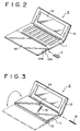
- Fig. 2 is a perspective view of the personal computer 2
- Fig. 3 is a perspective view of the personal computer 2 with its tablet positioned in an operable state.
- a lid 12 is attached rotatably to a pivot at the back of a body 11 of the personal computer 2.
- a tablet 13 is attached rotatably to another pivot at the front of the body 11.
- the lid 12 houses a liquid crystal display (LCD) panel 14, and the body 11 incorporates a keyboard.
- the personal computer 2 is readied for operation when the lid 12 is swung open from the body 11 and the tablet 13 is unfolded in an arrowed direction in Fig. 3 .
- the keyboard is then operated to activate desired application software while the LCD panel 14 is being visually checked.
- the personal computer 2 has one of its pivots equipped with a switch to turn on and off the tablet 13 depending on the rotated tablet position. Specifically, when the tablet 13 is folded in an overlaid fashion onto the keyboard (as shown in Fig. 3 ), the switch is activated to render the tablet 13 operable.
- the personal computer 2 is thus reduced in size for improved portable usage.
- the tablet 13 with its enlarged surface area is easier to operate than before.
- a slot 13A formed at the right-hand edge of the tablet 13 accommodates the IC card 3.
- an indicator composed of a light-emitting diode 14B.
- Loading the IC card 3 into the slot 13A illuminates the light-emitting diode (LED) 14B.
- the LED 14B blinks while the IC card 3 is being accessed.
- One edge of the body 11 houses a pen 15 that serves as a pointing device for operating the tablet 13.
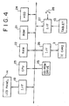
- Fig. 4 is a block diagram of the personal computer 2.
- the personal computer 2 allocates a work area in a random access memory (RAM) 22 according to data held in a read-only memory (ROM) 21, and gets a central processing unit (CPU) 23 to execute programs stored on a hard disk drive (HDD) 24.
- RAM random access memory
- ROM read-only memory
- HDD hard disk drive
- the personal computer 2 drives the LCD panel 14 through an interface 19 to generate a display screen.
- a CD-ROM set in a CD-ROM drive 25 is accessed illustratively so as to load map information therefrom.
- the personal computer 2 gains access to the IC card 3 through another interface 26, and displays a cursor and other indications based on coordinate information entered through the tablet 13 by way of another interface 27.
- the interface 27 of the personal computer 2 detects a swinging motion of the tablet 13 by means of a switch 28 incorporated in the pivot of the tablet 13. Specifically, when the tablet 13 is folded in an overlaid fashion onto the keyboard, the switch 28 is activated to let coordinate data be input through the tablet 13. As long as the tablet 13 is in the unfolded state, the personal computer 2 inhibits coordinate data acquisition through the tablet 13. In this manner, an unfolded tablet 13 is not inadvertently operated if it comes into accidental contact with diverse objects.
- the interface 26 is connected to the IC card 3 through a connector located deep inside the above-mentioned slot 13A.
- the interface 26 monitors the voltage of a predetermined terminal of the connector, detecting insertion or removal of the card when the terminal voltage is changed. Once the IC card 3 is found inserted, the card 3 is accessed and a check is made to see if the card 3 is properly loaded. If the IC card 3 is judged to be appropriately inserted, the LED 14B is illuminated. While the IC card 3 is being accessed under control of the CPU 23, the LED 14B is made to blink.
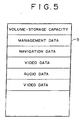
- Fig. 5 is a schematic view showing a typical memory space of the IC card 3.
- a volume and a total storage capacity of the card are recorded at the top of the memory space followed by a management data table and user areas.
- the user areas comprise navigation data files, video data files and audio data files.
- the management data table records user area management data such as addresses of files recorded in the user areas, dates and times of day of recordings, information about locations where the recordings were made, file types (navigation data, video data, audio data, text data, compressed format, etc.), and the remaining storage capacity.
- the management data also include relations between files recorded in the user areas. The relations are established by pointers each made up of a predetermined number of bits.
- a file recorded in a user area of the IC card 3 is a video data file
- management data recorded in conjunction with the file permit detection of the location where the recording was made.
- the relations associated with the file reveal illustratively that the file in question was recorded during a trip conducted in accordance with specific navigation data.
- the interface 26 accesses the card in keeping with an application program currently in use.
- a volume, a total storage capacity and management data are retrieved from the IC card 3 and sent to the CPU 23. If a user area is accessed and updated in accordance with the application program executed as per the management data, the management data are updated to reflect the changes of the user area under control of the CPU 23.
- Fig. 6 is a schematic view of a display screen generated by car navigation software, i.e., an application program carried out in the manner described above.
- the CPU 23 permits settings of a starting point, a halfway stop, a destination, and a route connecting these points by use of the keyboard and the tablet 13.
- the CPU 23 then writes to the IC card 3 data on the established route as car navigation data along with data about the date of the trip.
- Fig. 7 is a schematic view of another display screen generated by image processing software working in concert with the car navigation software.
- the CPU 23 displays on a map the car navigation data recorded in the IC card 3 by the user's operation. If the management data in the IC card 3 include still image data associated with the car navigation data, then locations where recordings were made are displayed on the map in accordance with the location information about the files involved.
- the number of captured images M i.e., number of images recorded in the IC card 3
- the image count M appears in each of rectangular frames showing images, indicating the number of images picked up in each recording location.
- the image count indication may be dragged by operation of the tablet 13 into a display area AR1 to the right as shown by an arrow A.
- the drag action causes the data about the corresponding file to be loaded from the IC card 3 for display into the area AR1.
- the personal computer 2 permits easy verification of image data that are recorded in the IC card 3 along with location information in conjunction with car navigation data.
- An appropriate operation by the user causes the CPU 23 to output the displayed still images onto a printer or through other means.
- Fig. 8 is a perspective view of the car navigation apparatus 4.
- the apparatus 4 is accommodated illustratively in a dashboard of a vehicle.
- the user pushes the apparatus as a whole.
- the pushing action causes the entire apparatus temporarily to move forward to let a liquid crystal display (LCD) part 30 collapse backward before the whole assembly retracts back into the dashboard.
- the user pushes the apparatus housing exposed on the dashboard.
- the user's pushing action causes the apparatus 4 as a whole to move forward to let the LCD part 30 stand upright before the entire assembly moves back into an operable state (as shown in Fig. 8 ).
- a long, narrow opening 31 is formed at the front of the car navigation apparatus 4.
- a CD or a CD-ROM is loaded through the opening 31 into the apparatus 4.
- An upper part of the opening 31 projects in a rectangular fashion.
- One side of the rectangular projection has a slot 32 formed to accommodate the IC card 3.
- the LCD part 30 of the car navigation apparatus 4 comprises an LCD panel 33. At the bottom of the LCD part 30 are various controls 34.
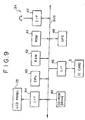
- Fig. 9 is a block diagram of the car navigation apparatus 4.
- the car navigation apparatus 4 allocates a work area in a random access memory (RAM) 42 in accordance with data held in a read-only memory (ROM) 41, and executes car navigation software under control of a central processing unit (CPU) 43.
- a display screen is generated by the LCD panel 33 driven through an interface 44.
- a CD-ROM loaded in a CD-ROM drive 45 is accessed and map information is illustratively loaded therefrom.
- the IC card 3 is accessed through an interface 46, and operations of the controls 34 are detected through an interface 47.
- current location information is acquired by a GPS (Global Positioning System) receiver 48, and route information retrieved from the IC card 3 is displayed for guide purposes in reference to the current location information thus acquired.
- GPS Global Positioning System
- the car navigation apparatus 4 When the user operates specific controls, the car navigation apparatus 4 gains access to the CD-ROM drive 45 according to the navigation data retrieved from the IC card 3, and loads map information corresponding to the route stored in the IC card 3. A map based on the map information is displayed on the LCD panel 33, and the retrieved route is indicated on this map. In addition, the car navigation apparatus 4 offers guidance along the retrieved route based on the current location information from the GPS receiver 48. In this manner, the car navigation apparatus 4 guides the user along the route established previously after careful consideration.
- the car navigation apparatus 4 displays still images retrieved from the IC card 3 in response to the user's operation on the controls 34. Those relations between files which are assigned to management data are adhered to for display. Illustratively, as in the case of Fig. 7 , a still image taken at the preceding rest stop and recorded in the IC card 3 is displayed by the car navigation apparatus 4 in accordance with suitable location information. In addition, still images about the tourist spot recorded in the IC card 3 at the advance selection of the route are displayed so that the location information about each still image as well as the relations between the files may be efficiently utilized, whereby the ease of use of the car navigation apparatus 4 is improved.
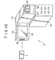
- Fig. 10 is a perspective view of the video camera 5 as it is viewed from the back.
- the video camera 5 takes pictures of a desired object through a lens 51 mounted at the front of the camera. Motion images are recorded on a video tape and still images are recorded to the IC card 3 by operation of suitable camera controls.
- the video camera 5 as a whole has a rectangular shape and comprises a video deck portion 52 constituting a video tape recorder in the lower part of the camera.
- the lens 51 is mounted at the top front of the video camera 5.
- An electronic viewfinder 53 is located on the opposite side of the lens 51.
- a side lid 54 is swung away from the body of the video camera 5. Inside the lid 54 is a liquid crystal display panel 55.
- An edge of the lid 54 has a slot 56 that accommodates the IC card 3.
- Various controls are located on the opposite side of the lid 54 and at the back of the video deck portion 52. Under the electronic viewfinder 53 are controls 57 and 58 for recording motion and still images respectively.
- Fig. 11 is a block diagram showing a configuration of the video camera 5.
- a CCD solid-state image pickup device 60 forms optical images on its light-receiving plane through a lens arrangement, not shown, and outputs the captured optical images.
- a sample hold (S/H) AGC circuit 61 subjects the captured images to correlated double sampling followed by signal level correction, thereby generating and outputting red, blue and green color signals.
- An analog-digital conversion circuit (A/D) 62 subjects the red, blue and green color signals to analog-to-digital conversion, and outputs digital red, blue and green color signals.
- a camera signal processing circuit 63 receives the digital color signals and subjects them to such corrective processes as gamma correction and knee correction before computing the corrected signals through matrix operations. In so doing, the camera signal processing circuit 63 generates and outputs digital luminance and color difference signals.
- a hand blur correction circuit 64 subjects the digital luminance and color difference signals from the camera signal processing circuit 63 to hand blur correction, and outputs the corrected results through electronic zooming.
- an image compression/decompression circuit 65 forwards the luminance and color difference signals from the hand blur correction circuit 64 to a display control circuit 66.
- the image compression/decompression circuit 65 compresses the luminance and color difference signals from the hand blur correction circuit 64 in response to an operation of the control 57 for motion image recording.
- the compressed video data are output to the video deck portion 52.
- the image compression/decompression circuit 65 decompresses video data from the video deck portion 52 and outputs the decompressed data to the display control circuit 66.
- the image compression/decompression circuit 65 compresses luminance and color difference signals illustratively on an MPEG (Moving Picture Experts Group) standard basis, for example.
- MPEG Motion Picture Experts Group
- the video deck portion 52 Under control of a system controller 68, the video deck portion 52 records video data from the image compression/decompression circuit 65 and audio data from an audio data compression/decompression circuit 70 onto a video tape. Conversely, the video deck portion 52 reproduces video and audio data from a video tape and outputs the reproduced data to the image compression/decompression circuit 65 and audio data compression/decompression circuit 70. In this manner, the video camera 5 records and reproduces captured motion images.
- an image compression/decompression circuit 71 compresses luminance and color difference signals from the hand blur correction circuit 64 in response to the control 58 operated for still image recording.
- the compressed video data are output to an interface 72.
- the image compression/decompression circuit 71 decompresses video data coming from the interface 72 and outputs the decompressed data to the display control circuit 66.
- the image compression/decompression circuit 71 compresses luminance and color difference signals illustratively on a JPEG (Joint Photographic Coding Experts Group) standard basis, for example.
- the interface 72 monitors a terminal voltage of the connector accommodating the IC card 3, and detects insertion or removal of the card upon a change in the terminal voltage.
- the card is accessed and a check is made to see if the card is correctly loaded. If the IC card 3 is judged to be properly inserted, a light-emitting diode (not shown) is made to blink.
- the IC card 3 is again accessed: video data from the image compression/decompression circuit 71 and audio data from the audio data compression/decompression circuit 70 are recorded to the card; or video and audio data are retrieved from the card for output to the image compression/decompression circuit 71 and audio data compression/decompression circuit 70.
- the video camera 5 is operated to record captured still images along with audio signals to the IC card 3 and to reproduce recorded contents of the card for verification.
- the corresponding management data are also updated through the interface 72 under control of the system controller 68.
- the interface 72 supplements file types making up the management data with recording location information from a GPS receiver 74 as well as information about relations to car navigation data.
- the video camera 5 thus makes it possible for the above-described car navigation apparatus 4 and personal computer 2 easily to process the recordings in the IC card 3.
- the interface 72 causes the LED to blink while the IC card 3 is being accessed.
- the blinking light warns the user against accidental and destructive removal of the IC card 3 during operation.
- the display control circuit 66 exchanges data with the system controller 68.
- the data exchanges allow operating information about the video camera 5 to be output superimposed on the luminance and color difference signals output by the image compression/decompression circuit 65 or 71.
- a digital-analog conversion circuit (D/A) 76 subjects luminance and color difference signals from the display control circuit 66 to digital-to-analog conversion, and outputs analog luminance and color difference signals. Given the analog luminance and color difference signals, a driver 77 drives the electronic viewfinder 53 and the LCD panel 55. The video camera 5 thus allows the user to verify captured images being reproduced and to visually check information about overall system performance.
- D/A digital-analog conversion circuit
- a microphone 78 picks up sound from an object and outputs an audio signal representing the collected sound.
- An amplifier 79 amplifies the audio signal from the microphone 78 with a predetermined gain and outputs the amplified signal.
- An analog-digital conversion circuit (A/D) 80 subjects the audio signal from the amplifier 79 to analog-to-digital conversion and outputs a digital audio signal.
- the audio data compression/decompression circuit 70 compresses the received digital audio data and sends the compressed audio data to the video deck portion 52 and interface 72 for recording. For reproduction, audio data from the video deck portion 52 and interface 72 are decompressed by the audio data compression/decompression circuit 70 conversely for output.
- the audio data compression/decompression circuit 70 subjects the audio signal to bandwidth division on an ATRAC (Adaptive Transform Acoustic Coding) standard basis followed by spectrum transformation.
- ATRAC Adaptive Transform Acoustic Coding
- a digital-analog conversion circuit (D/A) 81 subjects audio data from the audio data compression/decompression circuit 70 to digital-to-analog conversion.
- the resulting analog data are sent to an amplifier 82 for audio signal amplification.
- the amplified audio signal from the amplifier 82 is fed to a speaker 83 for acoustic output.
- the video camera 5 records picked-up sound along with captured images and permits the recorded sound to be played back for on-the-spot verification.
- the GPS receiver 74 detects and outputs information about the location of the video camera 5.
- the system controller 68 comprises a microcomputer that controls performance of the entire video camera 5 in response to operations of the controls (57, 58, etc.) at the back of the video camera 5.
- the system controller 68 also outputs operating information as needed to the display control circuit 66.
- inserting the IC card 3 prompts the system controller 68 to switch the overall operation from motion image recording to still image recording.
- the system controller 68 allows still images to be recorded to the IC card 3 in response to an operation of the control 58, discontinuing the recording of motion images by the video deck portion 52 following the operation of the control 57.
- the system controller 68 allows motion images to be recorded by the video deck portion 52 in response to an operation of the control 57 and still images to be recorded to the IC card 3 following the operation of the control 58. In this manner, the system controller 68 permits simultaneous and parallel recording of motion and still images.
- the system controller 68 retains location information acquired by the GPS receiver 74 as information about the location where the recording is carried out. If the management data in the IC card 3 reveal the existence of any still images previously recorded in approximately the same location, relations to such images are registered so that the images are associated with the current still image file. If captured still images are judged to be related to data about the date of the trip conducted by car navigation (i.e., if the route based on the car navigation data is being traveled on that day), the still images are associated upon recording with the file of the car navigation data in question.
- the video camera 5 allows the above-described car navigation apparatus 4 and personal computer 2 easily to process still images.
- the car navigation system 1 ( Fig. 1 ) utilizes the personal computer 2 illustratively to establish an itinerary, a destination, and rest stops of a trip thereby selecting a route connecting the established points.
- the route and itinerary of the trip are recorded in the IC card 3 as car navigation data.
- the user When the IC card 3 is loaded into the car navigation apparatus 4, the user may be guided along the previously established route. While on the move, the user may take pictures at rest stops with the IC card 3 removed from the car navigation apparatus 4 and loaded into the video camera 5 for image pickup.
- the loading of the IC card 3 is detected by the interface 72.
- the detection of the card prompts the system controller 68 to switch the operation of the video camera 5 from motion image recording to still image recording.
- the user verifies a desired object through the electronic viewfinder 53 and LCD panel 55 before operating the control 58 for image pickup.
- Activation of the control 58 records still image video data to the IC card 3. That is, simply loading the IC card into the video camera 5 allows still images to be recorded instead of motion images. This provides a significant improvement in the ease of operation of the video camera 5.
- the GPS receiver 74 in the video camera 5 Upon recording of still images to the IC card 3, the GPS receiver 74 in the video camera 5 detects information about the current location and records the location information as recording location data within the management data regarding each still picture file. The procedure permits easy recording of the information about locations where the recordings were made.
- a recording date of given data is used as a basis for judging whether the data in question are related to the car navigation data stored in the IC card 3. If the data are judged to be related data, relations are recorded between the data and the file of the car navigation data. If a plurality of still images are found to be recorded in about the same location on the basis of the location information acquired by the GPS receiver 74, relations are also recorded between files accommodating these still images.
- the IC card 3 with still images thus recorded therein is loaded back into the car navigation apparatus 4.
- the car navigation apparatus 4 causes the recorded still images to appear on the LCD panel 33 when the control 34 is operated.
- Each still image displayed indicates the corresponding recording location information as part of the management data, as well as relevant car navigation data and the number of other related still images taken in each of different recording locations shown on a map. Further operation of, say, the control 34 that invoked the current display may illustratively bring one still image after another onto the screen in a slide show fashion.
- the embodiment above thus allows the user to enjoy still images by making effective use of the location information recorded together with the images.
- Links to car navigation data are used to further facilitate still image display. This means that the associated use of the car navigation apparatus or like equipment allows location information to be used effectively in relation to each still image.
- each still image displayed indicates the number of other related still images taken in each of different recording locations shown on a map.
- Operating the keyboard that invoked the current display may illustratively bring one still image after another onto the screen in a slide show fashion.
- folding the opened tablet 13 onto the keyboard causes the interface 27 to detect the folding action enabling the tablet 13 to be operated.
- a still image count M is drawn with the pen 15 on the tablet 13
- a multiple-screen display shows still images associated with each recording location.
- the personal computer 2 is reduced in scale while the tablet 13 retains its relatively large size thanks to its folding structure.
- An enlarged tablet offers enhanced ease of operation to users.
- the above-described structure of the embodiment allows the video camera 5 to record the location information acquired by the GPS receiver as the information about recording locations in conjunction with captured still images.
- the video camera 5 thus permits easy recoding of information about the locations where the recordings were carried out.
- the IC card serving as a storage medium
- effective use is made of the information about the locations where such images were recorded illustratively in conjunction with the car navigation apparatus.
- the location information stored in the IC card proves more convenient than ever when utilized suitably by the user.
- still images are recorded to the IC card in relation to information about a route to a destination, i.e., to car navigation data.
- the related recording of still images allows not only recording locations to be indicated along the route on a map display but also the number of captured still images and contents of the recordings to be indicated in association with each recording location. Similar displays may also be made available on the car navigation apparatus.
- the embodiment above was described as capable of acquiring information about recording locations through a built-in GPS receiver of the video camera.
- the location information may be obtained through a GPS receiver of the car navigation apparatus or by other means.
- the preceding embodiment was shown having still images displayed by use of the personal computer or car navigation apparatus.
- the invention may be adapted to other displaying equipment such as TV sets.
- the above embodiment was shown applied to the car navigation apparatus described as a typical navigation device.
- the invention may be applied extensively to other navigation apparatuses such as navigation systems for use on board ships and vessels.
- captured images and location information are recorded in relation to one another, and the location information is utilized in displaying the captured still images. This makes it easy to record the information about the locations where the recordings were made, whereby the location information is readily utilized for car navigation purposes in particular.
Landscapes
- Engineering & Computer Science (AREA)
- Radar, Positioning & Navigation (AREA)
- Remote Sensing (AREA)
- Multimedia (AREA)
- Automation & Control Theory (AREA)
- Signal Processing (AREA)
- Physics & Mathematics (AREA)
- General Physics & Mathematics (AREA)
- Navigation (AREA)
- Traffic Control Systems (AREA)
- Studio Devices (AREA)
Claims (4)
- Datenverarbeitungsvorrichtung (4) zum Bereitstellen einer Route zu einem Ziel, aufweisend:- ein Mittel zum Abrufen (43, 46) von Navigationsdaten, welche die Route definieren, aus einem beweglichen Speichermedium (3), auf dem die Navigationsdaten gespeichert sind,- ein Mittel zum Abrufen (43, 46) von aufgezeichneten Bilddaten, die auf dem beweglichen Speichermedium (3) gespeichert sind, und zum Abrufen von Positionsdaten, die mit den aufgezeichneten Bilddaten gespeichert sind und die Position anzeigen, wo die Bilddaten aufgezeichnet wurden, aus dem Speichermedium,
wobei das Mittel zum Abrufen (43, 46) dafür konfiguriert ist, Daten aus dem beweglichen Speichermedium (3) abzurufen, welches dafür ausgestaltet ist, mit einer Bildaufnahmevorrichtung (5) verwendet zu werden,
dadurch gekennzeichnet, dass- die Datenverarbeitungsvorrichtung (4) dafür geeignet ist, die Route anzuzeigen und an Positionen entlang der angezeigten Route Aufzeichnungspositionen der Bilddaten und/oder eine Zahl anzuzeigen, die eine Anzahl an Bildern identifiziert, die an einer Position aufgezeichnet wurden, wobei die Positionen entlang der angezeigten Route Positionen entsprechen, die aus den abgerufenen Positionsinformationen identifiziert werden, und auf eine Benutzeroperation Bilder anzuzeigen oder auszugeben, die für eine angezeigte Aufzeichnungsposition aufgezeichnet sind. - Datenverarbeitungsvorrichtung (4) nach Anspruch 1, wobei die Positionsdaten absolute Positionsdaten sind, die von einem Positionierungssystem, z.B. einem GPS-System bereitgestellt werden.
- Datenverarbeitungsverfahren zum Bereitstellen einer Route zu einem Ziel, umfassend:- Abrufen von Navigationsdaten, welche die Route definieren, aus einem beweglichen Speichermedium (3), auf dem die Navigationsdaten gespeichert sind,- Abrufen von aufgezeichneten Bilddaten, die auf dem beweglichen Speichermedium (3) gespeichert sind, und Abrufen von Positionsdaten, die mit den aufgezeichneten Bilddaten gespeichert sind und anzeigen, wo die Bilddaten aufgezeichnet wurden, aus dem Speichermedium,
wobei die Daten durch ein Mittel zum Abrufen (43, 46) abgerufen werden, welches dafür konfiguriert ist, Daten aus dem beweglichen Speichermedium (3) abzurufen, welches dafür ausgestaltet ist, mit einer Bildaufnahmevorrichtung (5) verwendet zu werden,
gekennzeichnet durch- Anzeigen der Route und an Positionen entlang der angezeigten Route Anzeigen von Aufzeichnungspositionen der Bilddaten und/oder einer Zahl, welche die Anzahl an Bildern identifiziert, die an einer Position aufgezeichnet wurden, wobei die Positionen entlang der angezeigten Route Positionen entsprechen, die aus den abgerufenen Positionsinformationen identifiziert werden, und Anzeigen oder Ausgeben von Bildern, die für eine angezeigte Aufzeichnungsposition aufgezeichnet sind, auf eine Benutzeroperation. - Computerprogrammprodukt, welches, wenn es auf einem Computer ausgeführt wird, das Verfahren nach Anspruch 3 durchführt.
Priority Applications (1)
| Application Number | Priority Date | Filing Date | Title |
|---|---|---|---|
| EP15193438.7A EP3051802B1 (de) | 1998-07-27 | 1999-07-27 | Informationsverarbeitung zum anzeigen einer route zu einem zielort |
Applications Claiming Priority (2)
| Application Number | Priority Date | Filing Date | Title |
|---|---|---|---|
| JP10211529A JP2000050123A (ja) | 1998-07-27 | 1998-07-27 | 撮像装置、ナビゲーション装置、icカード及び静止画像の表示方法 |
| EP99114683A EP0977433B1 (de) | 1998-07-27 | 1999-07-27 | Bildaufnahmegerät zum Aufzeichnen von Bildern in Verbindung mit Ortsinformation |
Related Parent Applications (1)
| Application Number | Title | Priority Date | Filing Date |
|---|---|---|---|
| EP99114683A Division EP0977433B1 (de) | 1998-07-27 | 1999-07-27 | Bildaufnahmegerät zum Aufzeichnen von Bildern in Verbindung mit Ortsinformation |
Related Child Applications (2)
| Application Number | Title | Priority Date | Filing Date |
|---|---|---|---|
| EP15193438.7A Division EP3051802B1 (de) | 1998-07-27 | 1999-07-27 | Informationsverarbeitung zum anzeigen einer route zu einem zielort |
| EP15193438.7A Division-Into EP3051802B1 (de) | 1998-07-27 | 1999-07-27 | Informationsverarbeitung zum anzeigen einer route zu einem zielort |
Publications (3)
| Publication Number | Publication Date |
|---|---|
| EP1890488A2 EP1890488A2 (de) | 2008-02-20 |
| EP1890488A3 EP1890488A3 (de) | 2008-02-27 |
| EP1890488B1 true EP1890488B1 (de) | 2016-02-17 |
Family
ID=16607398
Family Applications (3)
| Application Number | Title | Priority Date | Filing Date |
|---|---|---|---|
| EP15193438.7A Expired - Lifetime EP3051802B1 (de) | 1998-07-27 | 1999-07-27 | Informationsverarbeitung zum anzeigen einer route zu einem zielort |
| EP99114683A Expired - Lifetime EP0977433B1 (de) | 1998-07-27 | 1999-07-27 | Bildaufnahmegerät zum Aufzeichnen von Bildern in Verbindung mit Ortsinformation |
| EP07122741.7A Expired - Lifetime EP1890488B1 (de) | 1998-07-27 | 1999-07-27 | Datenverarbeitung zur Bildanzeige einer Route zu einem Ziel |
Family Applications Before (2)
| Application Number | Title | Priority Date | Filing Date |
|---|---|---|---|
| EP15193438.7A Expired - Lifetime EP3051802B1 (de) | 1998-07-27 | 1999-07-27 | Informationsverarbeitung zum anzeigen einer route zu einem zielort |
| EP99114683A Expired - Lifetime EP0977433B1 (de) | 1998-07-27 | 1999-07-27 | Bildaufnahmegerät zum Aufzeichnen von Bildern in Verbindung mit Ortsinformation |
Country Status (4)
| Country | Link |
|---|---|
| US (4) | US6903763B1 (de) |
| EP (3) | EP3051802B1 (de) |
| JP (1) | JP2000050123A (de) |
| DE (1) | DE69937929T2 (de) |
Families Citing this family (66)
| Publication number | Priority date | Publication date | Assignee | Title |
|---|---|---|---|---|
| JP2000194726A (ja) * | 1998-10-19 | 2000-07-14 | Sony Corp | 情報処理装置及び方法、情報処理システム並びに提供媒体 |
| JP2001094916A (ja) * | 1999-09-17 | 2001-04-06 | Sony Corp | 情報処理方法および装置、並びにプログラム格納媒体 |
| JP3513084B2 (ja) | 2000-06-14 | 2004-03-31 | 株式会社東芝 | 情報処理システム、情報機器及び情報処理方法 |
| US7865306B2 (en) * | 2000-09-28 | 2011-01-04 | Michael Mays | Devices, methods, and systems for managing route-related information |
| US6351710B1 (en) * | 2000-09-28 | 2002-02-26 | Michael F. Mays | Method and system for visual addressing |
| JP2002150474A (ja) * | 2000-11-13 | 2002-05-24 | Sony Corp | 情報処理装置および方法、表示システム、並びにプログラム格納媒体 |
| JP4622101B2 (ja) | 2000-12-27 | 2011-02-02 | ソニー株式会社 | 情報処理装置、情報処理装置の情報処理方法および情報処理システム |
| US7508946B2 (en) | 2001-06-27 | 2009-03-24 | Sony Corporation | Integrated circuit device, information processing apparatus, memory management method for information storage device, mobile terminal apparatus, semiconductor integrated circuit device, and communication method using mobile terminal apparatus |
| EP1349363B1 (de) * | 2002-03-29 | 2014-01-08 | FUJIFILM Corporation | Digitale Kamera in Verbindung mit einem Navigationsystem und einem externen Speicherinformationssystem |
| JP2004032131A (ja) * | 2002-06-24 | 2004-01-29 | Canon Inc | 撮像装置及び画像処理装置 |
| EP1379085A1 (de) * | 2002-07-04 | 2004-01-07 | Deutsche Thomson-Brandt Gmbh | Verfahren und Anlage zum Verknüpfen von Multimediadaten |
| US8797402B2 (en) * | 2002-11-19 | 2014-08-05 | Hewlett-Packard Development Company, L.P. | Methods and apparatus for imaging and displaying a navigable path |
| JP4032355B2 (ja) * | 2003-03-27 | 2008-01-16 | カシオ計算機株式会社 | 表示処理装置、表示制御方法および表示処理プログラム |
| JP3725134B2 (ja) * | 2003-04-14 | 2005-12-07 | 株式会社エヌ・ティ・ティ・ドコモ | 移動通信システム、移動通信端末、及びプログラム。 |
| US7526718B2 (en) * | 2003-04-30 | 2009-04-28 | Hewlett-Packard Development Company, L.P. | Apparatus and method for recording “path-enhanced” multimedia |
| JP3962829B2 (ja) * | 2003-08-22 | 2007-08-22 | カシオ計算機株式会社 | 表示装置、表示方法、及び、表示プログラム |
| CA2559726C (en) * | 2004-03-24 | 2015-10-20 | A9.Com, Inc. | System and method for displaying images in an online directory |
| US20070083429A1 (en) * | 2005-10-11 | 2007-04-12 | Reiner Kraft | Enabling contextually placed ads in print media |
| JP2006072642A (ja) * | 2004-09-01 | 2006-03-16 | Noritsu Koki Co Ltd | 観光情報案内装置 |
| US20060170956A1 (en) | 2005-01-31 | 2006-08-03 | Jung Edward K | Shared image devices |
| US8902320B2 (en) | 2005-01-31 | 2014-12-02 | The Invention Science Fund I, Llc | Shared image device synchronization or designation |
| US9910341B2 (en) | 2005-01-31 | 2018-03-06 | The Invention Science Fund I, Llc | Shared image device designation |
| US9325781B2 (en) | 2005-01-31 | 2016-04-26 | Invention Science Fund I, Llc | Audio sharing |
| US9082456B2 (en) | 2005-01-31 | 2015-07-14 | The Invention Science Fund I Llc | Shared image device designation |
| US9489717B2 (en) | 2005-01-31 | 2016-11-08 | Invention Science Fund I, Llc | Shared image device |
| US20060174203A1 (en) * | 2005-01-31 | 2006-08-03 | Searete Llc, A Limited Liability Corporation Of The State Of Delaware | Viewfinder for shared image device |
| US9124729B2 (en) | 2005-01-31 | 2015-09-01 | The Invention Science Fund I, Llc | Shared image device synchronization or designation |
| US9001215B2 (en) | 2005-06-02 | 2015-04-07 | The Invention Science Fund I, Llc | Estimating shared image device operational capabilities or resources |
| US9076208B2 (en) | 2006-02-28 | 2015-07-07 | The Invention Science Fund I, Llc | Imagery processing |
| US9819490B2 (en) | 2005-05-04 | 2017-11-14 | Invention Science Fund I, Llc | Regional proximity for shared image device(s) |
| US20070222865A1 (en) | 2006-03-15 | 2007-09-27 | Searete Llc, A Limited Liability Corporation Of The State Of Delaware | Enhanced video/still image correlation |
| US8964054B2 (en) | 2006-08-18 | 2015-02-24 | The Invention Science Fund I, Llc | Capturing selected image objects |
| US9191611B2 (en) | 2005-06-02 | 2015-11-17 | Invention Science Fund I, Llc | Conditional alteration of a saved image |
| US9621749B2 (en) | 2005-06-02 | 2017-04-11 | Invention Science Fund I, Llc | Capturing selected image objects |
| US9967424B2 (en) | 2005-06-02 | 2018-05-08 | Invention Science Fund I, Llc | Data storage usage protocol |
| US9942511B2 (en) | 2005-10-31 | 2018-04-10 | Invention Science Fund I, Llc | Preservation/degradation of video/audio aspects of a data stream |
| US10003762B2 (en) | 2005-04-26 | 2018-06-19 | Invention Science Fund I, Llc | Shared image devices |
| US9451200B2 (en) | 2005-06-02 | 2016-09-20 | Invention Science Fund I, Llc | Storage access technique for captured data |
| JP4765395B2 (ja) * | 2005-05-11 | 2011-09-07 | カシオ計算機株式会社 | 画像撮影制御装置、画像編集装置及びプログラム |
| US20060293837A1 (en) * | 2005-06-02 | 2006-12-28 | Bennett James R | Photograph with map |
| US20070055441A1 (en) * | 2005-08-12 | 2007-03-08 | Facet Technology Corp. | System for associating pre-recorded images with routing information in a navigation system |
| US7509215B2 (en) * | 2005-12-12 | 2009-03-24 | Microsoft Corporation | Augmented navigation system |
| JP4740796B2 (ja) * | 2006-05-29 | 2011-08-03 | パナソニック株式会社 | 画像記録再生装置 |
| US20070284450A1 (en) * | 2006-06-07 | 2007-12-13 | Sony Ericsson Mobile Communications Ab | Image handling |
| DE102006033147A1 (de) * | 2006-07-18 | 2008-01-24 | Robert Bosch Gmbh | Überwachungskamera, Verfahren zur Kalibrierung der Überwachungskamera sowie Verwendung der Überwachungskamera |
| US7712052B2 (en) * | 2006-07-31 | 2010-05-04 | Microsoft Corporation | Applications of three-dimensional environments constructed from images |
| JP3128845U (ja) * | 2006-11-09 | 2007-01-25 | 智基科技開發股▲ふん▼有限公司 | 画像ナビゲーション |
| WO2008129879A1 (ja) * | 2007-04-18 | 2008-10-30 | Panasonic Corporation | デジタル放送受信装置およびデジタル放送受信方法 |
| TW200847030A (en) * | 2007-05-30 | 2008-12-01 | Atp Electronics Taiwan Inc | Memory card with GPS module |
| TW200846956A (en) * | 2007-05-30 | 2008-12-01 | Atp Electronics Taiwan Inc | System capable of attaching positional information to image file and memory card |
| US20080309762A1 (en) * | 2007-06-12 | 2008-12-18 | Richie Howard | In-vehicle mobile digital video surveillance recorder system with GPS visual mapping and navigation |
| JP2009154647A (ja) * | 2007-12-26 | 2009-07-16 | Aisin Aw Co Ltd | マルチ画面表示装置及びそのプログラム |
| TW200939120A (en) * | 2008-03-14 | 2009-09-16 | Avid Electronics Corp | A multimedia device of generating multimedia files with geographical positions and a multimedia-file broadcasting method by the geographical-position relation |
| KR101077418B1 (ko) * | 2008-08-08 | 2011-10-26 | (주) 비앤디 | 내비게이션 제어 시스템 및 그 방법 |
| JP5517683B2 (ja) * | 2009-05-01 | 2014-06-11 | キヤノン株式会社 | 画像処理装置及びその制御方法 |
| US10408623B2 (en) * | 2009-06-12 | 2019-09-10 | Microsoft Technology Licensing, Llc | Retracing steps |
| US20110262103A1 (en) * | 2009-09-14 | 2011-10-27 | Kumar Ramachandran | Systems and methods for updating video content with linked tagging information |
| JP4893803B2 (ja) * | 2009-11-02 | 2012-03-07 | ソニー株式会社 | 情報処理装置、情報処理方法、情報処理システム |
| JP5287756B2 (ja) * | 2010-02-08 | 2013-09-11 | ソニー株式会社 | 画像処理装置、画像処理方法およびプログラム |
| US20110257972A1 (en) * | 2010-04-15 | 2011-10-20 | Markus Agevik | System and method for location tracking using audio input |
| CN101943582A (zh) * | 2010-07-02 | 2011-01-12 | 哈尔滨工程大学 | 基于ccd星敏感器与加速度计的惯性导航定位方法 |
| JP2013161390A (ja) * | 2012-02-08 | 2013-08-19 | Sony Corp | サーバ、クライアント端末、システム、およびプログラム |
| US10418068B2 (en) * | 2016-04-13 | 2019-09-17 | David Dat Tran | Visual data recording synchronization system |
| DE102019104505A1 (de) * | 2019-02-22 | 2020-08-27 | Dr. Ing. H.C. F. Porsche Aktiengesellschaft | Navigationssystem für ein Kraftfahrzeug |
| CN111798677B (zh) * | 2020-07-15 | 2021-12-03 | 安徽达尔智能控制系统股份有限公司 | 基于道路视频的交通事件监测指挥系统 |
| CN116698018B (zh) * | 2023-08-08 | 2023-10-13 | 山西戴德测控技术股份有限公司 | 一种导航定位辅助装置及煤矿巷道导航定位系统 |
Citations (3)
| Publication number | Priority date | Publication date | Assignee | Title |
|---|---|---|---|---|
| EP0377480A2 (de) * | 1989-01-06 | 1990-07-11 | Teleatlas International B.V. | Verfahren zum Einrichten und zur Aktualisierung der Datei für den Strassenverkehr |
| EP0836167A1 (de) * | 1996-08-21 | 1998-04-15 | Aisin Aw Co., Ltd. | Gerät zur Anzeige von Karten und Verfahren dazu |
| US20020001032A1 (en) * | 1996-11-15 | 2002-01-03 | Nippon Lsi Card Co., Ltd. | Portable computer, data management system using the same, and method of producing a map stored with actual photo-image data using the same portable computer and data management system |
Family Cites Families (15)
| Publication number | Priority date | Publication date | Assignee | Title |
|---|---|---|---|---|
| US4122521A (en) | 1975-10-20 | 1978-10-24 | Northrop Corporation | Correlation system for multiple-sensor reconnaissance vehicle |
| JPH0795220B2 (ja) * | 1986-10-31 | 1995-10-11 | パイオニア株式会社 | 地図の表示方法 |
| DE3726065A1 (de) | 1987-08-06 | 1988-01-21 | Friedhelm Fredrich | Kastenwagenkraftfahrzeug mit einer auswerteinrichtung im fahrerhaus, die einer bedienungsperson eine beurteilung eines objektes durch bildschirme und schallwandler erlaubt, wobei speziell die signale einer videokamera zur beurteilung des aufnahmewinkels dient |
| JPH0688734A (ja) | 1992-09-04 | 1994-03-29 | Pioneer Electron Corp | マップコミュニケーションシステム |
| US5528516A (en) * | 1994-05-25 | 1996-06-18 | System Management Arts, Inc. | Apparatus and method for event correlation and problem reporting |
| US5774569A (en) | 1994-07-25 | 1998-06-30 | Waldenmaier; H. Eugene W. | Surveillance system |
| US5528518A (en) * | 1994-10-25 | 1996-06-18 | Laser Technology, Inc. | System and method for collecting data used to form a geographic information system database |
| JPH0933270A (ja) | 1995-07-24 | 1997-02-07 | Sumitomo Electric Ind Ltd | ナビゲーション装置 |
| JP3658659B2 (ja) * | 1995-11-15 | 2005-06-08 | カシオ計算機株式会社 | 画像処理装置 |
| US5982298A (en) * | 1996-11-14 | 1999-11-09 | Microsoft Corporation | Interactive traffic display and trip planner |
| JP3766518B2 (ja) | 1997-01-07 | 2006-04-12 | ペンタックス株式会社 | センサ内蔵カメラ |
| US6199014B1 (en) * | 1997-12-23 | 2001-03-06 | Walker Digital, Llc | System for providing driving directions with visual cues |
| US6285317B1 (en) * | 1998-05-01 | 2001-09-04 | Lucent Technologies Inc. | Navigation system with three-dimensional display |
| US6182010B1 (en) * | 1999-01-28 | 2001-01-30 | International Business Machines Corporation | Method and apparatus for displaying real-time visual information on an automobile pervasive computing client |
| JP2003050846A (ja) * | 2001-08-07 | 2003-02-21 | Hitachi Ltd | 情報伝達システム及びそれに用いる旅行サーバ及び携帯端末及び情報伝達方法 |
-
1998
- 1998-07-27 JP JP10211529A patent/JP2000050123A/ja active Pending
-
1999
- 1999-07-22 US US09/358,520 patent/US6903763B1/en not_active Expired - Lifetime
- 1999-07-27 EP EP15193438.7A patent/EP3051802B1/de not_active Expired - Lifetime
- 1999-07-27 DE DE69937929T patent/DE69937929T2/de not_active Expired - Lifetime
- 1999-07-27 EP EP99114683A patent/EP0977433B1/de not_active Expired - Lifetime
- 1999-07-27 EP EP07122741.7A patent/EP1890488B1/de not_active Expired - Lifetime
-
2005
- 2005-03-18 US US11/082,879 patent/US7006131B2/en not_active Expired - Lifetime
- 2005-03-18 US US11/082,888 patent/US6970188B2/en not_active Expired - Lifetime
- 2005-03-21 US US11/083,942 patent/US7042498B2/en not_active Expired - Fee Related
Patent Citations (3)
| Publication number | Priority date | Publication date | Assignee | Title |
|---|---|---|---|---|
| EP0377480A2 (de) * | 1989-01-06 | 1990-07-11 | Teleatlas International B.V. | Verfahren zum Einrichten und zur Aktualisierung der Datei für den Strassenverkehr |
| EP0836167A1 (de) * | 1996-08-21 | 1998-04-15 | Aisin Aw Co., Ltd. | Gerät zur Anzeige von Karten und Verfahren dazu |
| US20020001032A1 (en) * | 1996-11-15 | 2002-01-03 | Nippon Lsi Card Co., Ltd. | Portable computer, data management system using the same, and method of producing a map stored with actual photo-image data using the same portable computer and data management system |
Also Published As
| Publication number | Publication date |
|---|---|
| US20050165542A1 (en) | 2005-07-28 |
| EP3051802A1 (de) | 2016-08-03 |
| US7006131B2 (en) | 2006-02-28 |
| US20050165541A1 (en) | 2005-07-28 |
| EP0977433A2 (de) | 2000-02-02 |
| US7042498B2 (en) | 2006-05-09 |
| EP0977433A3 (de) | 2000-11-02 |
| DE69937929D1 (de) | 2008-02-21 |
| US6903763B1 (en) | 2005-06-07 |
| US20050162533A1 (en) | 2005-07-28 |
| JP2000050123A (ja) | 2000-02-18 |
| EP1890488A2 (de) | 2008-02-20 |
| DE69937929T2 (de) | 2009-01-15 |
| US6970188B2 (en) | 2005-11-29 |
| EP1890488A3 (de) | 2008-02-27 |
| EP3051802B1 (de) | 2019-07-10 |
| EP0977433B1 (de) | 2008-01-09 |
Similar Documents
| Publication | Publication Date | Title |
|---|---|---|
| EP1890488B1 (de) | Datenverarbeitung zur Bildanzeige einer Route zu einem Ziel | |
| KR100234631B1 (ko) | 이미지 처리시스템 및 방법 | |
| US6816189B2 (en) | Electron camera and method of controlling the same | |
| US6584541B2 (en) | Method for storing digital information in write-once memory array | |
| US20110234849A1 (en) | Method and system for processing digital images having an association file separate from an image life | |
| US7619659B2 (en) | Image capturing apparatus having plural operation modes | |
| US20110032385A1 (en) | Image positioning method, poi tagging method and the apparatus | |
| JP2001005902A (ja) | 画像記録装置 | |
| US20030106724A1 (en) | Coordinate input apparatus and information processing apparatus | |
| US20110149089A1 (en) | System and method for generating an image appended with landscape information | |
| US7885515B2 (en) | Recording/reproducing device and recording/reproduction method | |
| EP1301032B1 (de) | Kamera, Kameraverbindbare Vorrichtung und Kamerassystem | |
| JPH09252454A (ja) | 画像記録再生装置 | |
| JPH0730792A (ja) | 電子スチルカメラ | |
| JP3728338B2 (ja) | カメラ | |
| JP4322363B2 (ja) | メモリ情報処理装置 | |
| JP3475119B2 (ja) | 電子アルバム装置 | |
| JP2010028282A (ja) | カメラおよび座標算出プログラム | |
| JP2001177795A (ja) | 電子撮像装置 | |
| JP2005175587A (ja) | 画像記録装置および画像再生装置 | |
| JP2002171474A (ja) | 画像記録再生装置 | |
| JPH10105050A (ja) | ナビゲーションシステム | |
| JP2003134426A (ja) | 情報記憶モジュール、及び情報処理システム |
Legal Events
| Date | Code | Title | Description |
|---|---|---|---|
| PUAI | Public reference made under article 153(3) epc to a published international application that has entered the european phase |
Free format text: ORIGINAL CODE: 0009012 |
|
| PUAL | Search report despatched |
Free format text: ORIGINAL CODE: 0009013 |
|
| 17P | Request for examination filed |
Effective date: 20071210 |
|
| AC | Divisional application: reference to earlier application |
Ref document number: 0977433 Country of ref document: EP Kind code of ref document: P |
|
| AK | Designated contracting states |
Kind code of ref document: A2 Designated state(s): DE FR GB |
|
| AK | Designated contracting states |
Kind code of ref document: A3 Designated state(s): DE FR GB |
|
| 17Q | First examination report despatched |
Effective date: 20080926 |
|
| AKX | Designation fees paid |
Designated state(s): DE FR GB |
|
| REG | Reference to a national code |
Ref country code: DE Ref legal event code: R079 Ref document number: 69945494 Country of ref document: DE Free format text: PREVIOUS MAIN CLASS: H04N0005907000 Ipc: H04N0001000000 |
|
| GRAP | Despatch of communication of intention to grant a patent |
Free format text: ORIGINAL CODE: EPIDOSNIGR1 |
|
| RIC1 | Information provided on ipc code assigned before grant |
Ipc: G01C 21/36 20060101ALI20150615BHEP Ipc: H04N 1/21 20060101ALI20150615BHEP Ipc: H04N 1/00 20060101AFI20150615BHEP |
|
| INTG | Intention to grant announced |
Effective date: 20150701 |
|
| GRAS | Grant fee paid |
Free format text: ORIGINAL CODE: EPIDOSNIGR3 |
|
| INTG | Intention to grant announced |
Effective date: 20151204 |
|
| GRAA | (expected) grant |
Free format text: ORIGINAL CODE: 0009210 |
|
| AC | Divisional application: reference to earlier application |
Ref document number: 0977433 Country of ref document: EP Kind code of ref document: P |
|
| AK | Designated contracting states |
Kind code of ref document: B1 Designated state(s): DE FR GB |
|
| REG | Reference to a national code |
Ref country code: GB Ref legal event code: FG4D |
|
| REG | Reference to a national code |
Ref country code: DE Ref legal event code: R096 Ref document number: 69945494 Country of ref document: DE |
|
| REG | Reference to a national code |
Ref country code: FR Ref legal event code: PLFP Year of fee payment: 18 |
|
| REG | Reference to a national code |
Ref country code: DE Ref legal event code: R097 Ref document number: 69945494 Country of ref document: DE |
|
| PLBE | No opposition filed within time limit |
Free format text: ORIGINAL CODE: 0009261 |
|
| STAA | Information on the status of an ep patent application or granted ep patent |
Free format text: STATUS: NO OPPOSITION FILED WITHIN TIME LIMIT |
|
| 26N | No opposition filed |
Effective date: 20161118 |
|
| REG | Reference to a national code |
Ref country code: FR Ref legal event code: PLFP Year of fee payment: 19 |
|
| REG | Reference to a national code |
Ref country code: FR Ref legal event code: PLFP Year of fee payment: 20 |
|
| PGFP | Annual fee paid to national office [announced via postgrant information from national office to epo] |
Ref country code: DE Payment date: 20180723 Year of fee payment: 20 Ref country code: FR Payment date: 20180725 Year of fee payment: 20 |
|
| PGFP | Annual fee paid to national office [announced via postgrant information from national office to epo] |
Ref country code: GB Payment date: 20180719 Year of fee payment: 20 |
|
| REG | Reference to a national code |
Ref country code: DE Ref legal event code: R071 Ref document number: 69945494 Country of ref document: DE |
|
| REG | Reference to a national code |
Ref country code: GB Ref legal event code: PE20 Expiry date: 20190726 |
|
| PG25 | Lapsed in a contracting state [announced via postgrant information from national office to epo] |
Ref country code: GB Free format text: LAPSE BECAUSE OF EXPIRATION OF PROTECTION Effective date: 20190726 |