EP1888199B1 - Spool valve manifold interconnect for a filter system - Google Patents
Spool valve manifold interconnect for a filter system Download PDFInfo
- Publication number
- EP1888199B1 EP1888199B1 EP20060784421 EP06784421A EP1888199B1 EP 1888199 B1 EP1888199 B1 EP 1888199B1 EP 20060784421 EP20060784421 EP 20060784421 EP 06784421 A EP06784421 A EP 06784421A EP 1888199 B1 EP1888199 B1 EP 1888199B1
- Authority
- EP
- European Patent Office
- Prior art keywords
- filter cartridge
- housing
- fluid
- cartridge
- valve
- Prior art date
- Legal status (The legal status is an assumption and is not a legal conclusion. Google has not performed a legal analysis and makes no representation as to the accuracy of the status listed.)
- Active
Links
- 239000012530 fluid Substances 0.000 claims description 193
- 238000004891 communication Methods 0.000 claims description 32
- 238000003780 insertion Methods 0.000 claims description 27
- 230000037431 insertion Effects 0.000 claims description 27
- 239000007788 liquid Substances 0.000 claims description 15
- 230000000295 complement effect Effects 0.000 claims description 12
- 238000001914 filtration Methods 0.000 description 21
- XLYOFNOQVPJJNP-UHFFFAOYSA-N water Substances O XLYOFNOQVPJJNP-UHFFFAOYSA-N 0.000 description 18
- 239000000463 material Substances 0.000 description 12
- 238000007667 floating Methods 0.000 description 6
- 230000003993 interaction Effects 0.000 description 6
- 238000007789 sealing Methods 0.000 description 6
- 230000006835 compression Effects 0.000 description 5
- 238000007906 compression Methods 0.000 description 5
- 238000009434 installation Methods 0.000 description 5
- 230000008901 benefit Effects 0.000 description 4
- 238000004519 manufacturing process Methods 0.000 description 4
- 229920002943 EPDM rubber Polymers 0.000 description 3
- 229920000459 Nitrile rubber Polymers 0.000 description 3
- 238000000034 method Methods 0.000 description 3
- -1 such as Substances 0.000 description 3
- 230000009471 action Effects 0.000 description 2
- 230000007246 mechanism Effects 0.000 description 2
- 238000012986 modification Methods 0.000 description 2
- 230000004048 modification Effects 0.000 description 2
- 239000004743 Polypropylene Substances 0.000 description 1
- CDBYLPFSWZWCQE-UHFFFAOYSA-L Sodium Carbonate Chemical compound [Na+].[Na+].[O-]C([O-])=O CDBYLPFSWZWCQE-UHFFFAOYSA-L 0.000 description 1
- 230000004913 activation Effects 0.000 description 1
- 238000013459 approach Methods 0.000 description 1
- 230000000712 assembly Effects 0.000 description 1
- 238000000429 assembly Methods 0.000 description 1
- 235000013361 beverage Nutrition 0.000 description 1
- 238000013329 compounding Methods 0.000 description 1
- 230000007423 decrease Effects 0.000 description 1
- 238000013461 design Methods 0.000 description 1
- 239000003651 drinking water Substances 0.000 description 1
- 235000020188 drinking water Nutrition 0.000 description 1
- 238000005516 engineering process Methods 0.000 description 1
- 239000011521 glass Substances 0.000 description 1
- 229920001519 homopolymer Polymers 0.000 description 1
- 230000013011 mating Effects 0.000 description 1
- 238000012544 monitoring process Methods 0.000 description 1
- 238000000465 moulding Methods 0.000 description 1
- 229920001155 polypropylene Polymers 0.000 description 1
- 230000002265 prevention Effects 0.000 description 1
- 230000008569 process Effects 0.000 description 1
- 239000002990 reinforced plastic Substances 0.000 description 1
- 230000003068 static effect Effects 0.000 description 1
- 239000000454 talc Substances 0.000 description 1
- 229910052623 talc Inorganic materials 0.000 description 1
- 238000013519 translation Methods 0.000 description 1
Images


Classifications
-
- B—PERFORMING OPERATIONS; TRANSPORTING
- B01—PHYSICAL OR CHEMICAL PROCESSES OR APPARATUS IN GENERAL
- B01D—SEPARATION
- B01D35/00—Filtering devices having features not specifically covered by groups B01D24/00 - B01D33/00, or for applications not specifically covered by groups B01D24/00 - B01D33/00; Auxiliary devices for filtration; Filter housing constructions
- B01D35/14—Safety devices specially adapted for filtration; Devices for indicating clogging
- B01D35/153—Anti-leakage or anti-return valves
-
- B—PERFORMING OPERATIONS; TRANSPORTING
- B01—PHYSICAL OR CHEMICAL PROCESSES OR APPARATUS IN GENERAL
- B01D—SEPARATION
- B01D27/00—Cartridge filters of the throw-away type
- B01D27/08—Construction of the casing
-
- B—PERFORMING OPERATIONS; TRANSPORTING
- B01—PHYSICAL OR CHEMICAL PROCESSES OR APPARATUS IN GENERAL
- B01D—SEPARATION
- B01D27/00—Cartridge filters of the throw-away type
- B01D27/10—Safety devices, e.g. by-passes
- B01D27/108—Flow control valves; Damping or calibrated passages
-
- B—PERFORMING OPERATIONS; TRANSPORTING
- B01—PHYSICAL OR CHEMICAL PROCESSES OR APPARATUS IN GENERAL
- B01D—SEPARATION
- B01D27/00—Cartridge filters of the throw-away type
- B01D27/10—Safety devices, e.g. by-passes
- B01D27/106—Anti-leakage or anti-return valves
-
- C—CHEMISTRY; METALLURGY
- C02—TREATMENT OF WATER, WASTE WATER, SEWAGE, OR SLUDGE
- C02F—TREATMENT OF WATER, WASTE WATER, SEWAGE, OR SLUDGE
- C02F9/00—Multistage treatment of water, waste water or sewage
-
- C—CHEMISTRY; METALLURGY
- C02—TREATMENT OF WATER, WASTE WATER, SEWAGE, OR SLUDGE
- C02F—TREATMENT OF WATER, WASTE WATER, SEWAGE, OR SLUDGE
- C02F9/00—Multistage treatment of water, waste water or sewage
- C02F9/20—Portable or detachable small-scale multistage treatment devices, e.g. point of use or laboratory water purification systems
-
- F—MECHANICAL ENGINEERING; LIGHTING; HEATING; WEAPONS; BLASTING
- F16—ENGINEERING ELEMENTS AND UNITS; GENERAL MEASURES FOR PRODUCING AND MAINTAINING EFFECTIVE FUNCTIONING OF MACHINES OR INSTALLATIONS; THERMAL INSULATION IN GENERAL
- F16K—VALVES; TAPS; COCKS; ACTUATING-FLOATS; DEVICES FOR VENTING OR AERATING
- F16K5/00—Plug valves; Taps or cocks comprising only cut-off apparatus having at least one of the sealing faces shaped as a more or less complete surface of a solid of revolution, the opening and closing movement being predominantly rotary
- F16K5/04—Plug valves; Taps or cocks comprising only cut-off apparatus having at least one of the sealing faces shaped as a more or less complete surface of a solid of revolution, the opening and closing movement being predominantly rotary with plugs having cylindrical surfaces; Packings therefor
- F16K5/0414—Plug channel at 90 degrees to the inlet
-
- B—PERFORMING OPERATIONS; TRANSPORTING
- B01—PHYSICAL OR CHEMICAL PROCESSES OR APPARATUS IN GENERAL
- B01D—SEPARATION
- B01D2201/00—Details relating to filtering apparatus
- B01D2201/40—Special measures for connecting different parts of the filter
- B01D2201/4023—Means for connecting filter housings to supports
-
- B—PERFORMING OPERATIONS; TRANSPORTING
- B01—PHYSICAL OR CHEMICAL PROCESSES OR APPARATUS IN GENERAL
- B01D—SEPARATION
- B01D2201/00—Details relating to filtering apparatus
- B01D2201/40—Special measures for connecting different parts of the filter
- B01D2201/4046—Means for avoiding false mounting of different parts
- B01D2201/4053—Means for avoiding false mounting of different parts using keys
-
- B—PERFORMING OPERATIONS; TRANSPORTING
- B01—PHYSICAL OR CHEMICAL PROCESSES OR APPARATUS IN GENERAL
- B01D—SEPARATION
- B01D2201/00—Details relating to filtering apparatus
- B01D2201/40—Special measures for connecting different parts of the filter
- B01D2201/4046—Means for avoiding false mounting of different parts
- B01D2201/4061—Means for avoiding false mounting of different parts between a cartridge and a filter head or manifold
-
- Y—GENERAL TAGGING OF NEW TECHNOLOGICAL DEVELOPMENTS; GENERAL TAGGING OF CROSS-SECTIONAL TECHNOLOGIES SPANNING OVER SEVERAL SECTIONS OF THE IPC; TECHNICAL SUBJECTS COVERED BY FORMER USPC CROSS-REFERENCE ART COLLECTIONS [XRACs] AND DIGESTS
- Y10—TECHNICAL SUBJECTS COVERED BY FORMER USPC
- Y10T—TECHNICAL SUBJECTS COVERED BY FORMER US CLASSIFICATION
- Y10T137/00—Fluid handling
- Y10T137/8593—Systems
- Y10T137/86493—Multi-way valve unit
- Y10T137/86863—Rotary valve unit
-
- Y—GENERAL TAGGING OF NEW TECHNOLOGICAL DEVELOPMENTS; GENERAL TAGGING OF CROSS-SECTIONAL TECHNOLOGIES SPANNING OVER SEVERAL SECTIONS OF THE IPC; TECHNICAL SUBJECTS COVERED BY FORMER USPC CROSS-REFERENCE ART COLLECTIONS [XRACs] AND DIGESTS
- Y10—TECHNICAL SUBJECTS COVERED BY FORMER USPC
- Y10T—TECHNICAL SUBJECTS COVERED BY FORMER US CLASSIFICATION
- Y10T29/00—Metal working
- Y10T29/49—Method of mechanical manufacture
- Y10T29/49826—Assembling or joining
Definitions
- the present disclosure relates in general to a system operatively positioned in a fluid supply system comprising a manifold assembly and a replaceable fluid filter cartridge containing filter media, the manifold assembly having the capability for facilitating the removal of a first replaceable fluid filter cartridge and then having the capability for facilitating the installation of another replaceable fluid filter cartridge therein in a fluid supply system and, in particular, to a spool valve manifold assembly that facilitates the quick and easy removal and installation of the replaceable fluid filter cartridges from and into the manifold assembly.
- Manifold assemblies having the capability for facilitating the removal of a first fluid filter cartridge and then having the capability for facilitating the installation of another replaceable fluid filter cartridge in a fluid supply system for industrial, commercial and consumer use are widely known throughout the industry.
- most modem refrigerators which provide drinking water and produce ice, and beverage dispensing machines, such as coffee makers and soda dispensers, use an internal fluid filtration system having replaceable fluid filter cartridges for filtering certain contaminates from the fluid, such as, water.
- Muzik discloses a gate-type valve, wherein a receptacle disk for receiving a filter is rotatably coupled to an upper plate having fluid supply inlet and outlet ports.
- the receptacle disk includes through passages for receiving inlet and outlet ports of the filter. When there is no filter inserted into these passages, the passages are not aligned with the fluid supply inlet and outlet ports of the upper plate. After insertion of the filter into the receptacle disk, the filter and the receptacle disk can be rotated around the longitudinal axis of the filter to align the inlet and outlet ports of the filter with the inlet and outlet ports of the fluid supply.
- US patent application No. US 2005/0067342 discloses a valve assembly for use in conjunction with a replaceable filter cartridge system.
- the valve assembly includes a head member having an interior valve chamber defining a central axis, and inlet and outlet passages extending parallel to and communicating with the interior valve chamber.
- the valve assembly further includes a valve member having an inlet path and an outlet path, adapted for rotation within the interior valve chamber of the head member between a filter position wherein the inlet path of the valve member is in communication with the inlet passage of the head member and a bypass position wherein the inlet path of the valve member is out of communication with the inlet passage of the head member.
- the valve assembly further includes a seal member seated in an upper surface of the valve member and positioned to seal against an opposing surface of the interior valve chamber.
- the seal member sealingly isolates untreated and treated fluid streams flowing through the inlet and outlet paths of the valve member, respectively, when the valve member is in the filter position, and sealingly isolates the inlet and outlet passages of the head member from the atmosphere when the valve member is in the bypass position to permit fluid to flow therebetween.
- valves can become hard to operate due to the sealing O-rings taking a compression set over time. Because of this compression set, a high breaking force to initially move the valve is required.
- a spool valve manifold comprising:
- a filter cartridge and spool valve manifold assembly comprising:
- the housing inlet port and the housing outlet port are in fluid communication via a third fluid flow path when the valve body is at the second rotational position relative to the valve housing.
- the housing inlet port and the housing outlet port are not in fluid communication when the valve body is at the second rotational position relative to the valve housing.
- valve housing further may include an insertion cam component configured to cooperate with a complementary insertion cam component on the filter cartridge.
- valve housing further may include an ejection cam component configured to cooperate with a complementary ejection cam component on the filter cartridge.
- the spool valve manifold further may include a first seal located between the valve body and the valve housing and configured to prevent fluid leakage from the first fluid flow path and a second seal located between the valve body and the valve housing and configured to prevent fluid leakage from the second fluid flow path.
- the spool valve manifold may also include a third seal located between the valve body and the valve housing and configured to prevent fluid leakage from the third fluid flow path.
- the angle between the first and second rotational positions may be less than 90 degrees.
- the filter cartridge includes a handle at an end of the filter cartridge that is opposite the inlet/outlet portion.
- a bracket is coupled to the valve housing and configured to mount the spool valve manifold to an appliance.
- a bracket is rotatably mounted adjacent the spool valve and configured to slidably hold the filter cartridge as the body rotates from the first to the second rotational position.
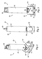
- Figure 1 is a perspective view of a fluid filter cartridge and spool valve manifold assembly according to a representative embodiment of the present disclosure, with the assembly shown in a first rotational position;
- Figure 2 is a side view of the fluid filter cartridge and spool valve manifold assembly according to the representative embodiment of Figure 1 ;
- Figure 3 is a front view of the fluid filter cartridge and spool valve manifold assembly according to the representative embodiment of Figure 1 ;
- Figure 4 is an exploded perspective view of the fluid filter cartridge and spool valve manifold assembly according to the representative embodiment of Figure 1 ;
- Figure 5 is a perspective view of the fluid filter cartridge and spool valve manifold assembly, according to a representative embodiment of Figure 1 , with the assembly shown in a second rotational position;
- Figure 6 is a side view of the fluid filter cartridge and spool valve manifold assembly according to the aspect of Figure 5 ;
- Figure 7 is a front view of the fluid filter cartridge and spool valve manifold assembly according to the aspect of Figure 5 ;
- Figure 8 is a side view of the fluid filter cartridge and spool valve manifold assembly according to the aspect of Figure 5 , with the fluid filter cartridge shown removed from the assembly;
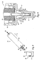
- Figure 9 is a cross-sectional side view of a portion of a fluid filter cartridge according to one representative embodiment of the present disclosure.
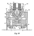
- Figure 10 is a partial cross-sectional side view of a portion of a fluid filter cartridge inserted into a spool valve manifold assembly according to a representative embodiment of the present disclosure, with the filter cartridge and valve body in a first rotational position;
- Figure 11 is a perspective view of a portion of the fluid filter cartridge and spool valve manifold assembly, with the valve housing shown partially transparent, and with the fluid filter cartridge and the valve body shown in the first rotational position;
- Figure 12 is a partial cross-sectional side view of a portion of a fluid filter cartridge inserted into a spool valve manifold assembly according to a representative embodiment of the present disclosure, with the fluid filter cartridge and the valve body in a second rotational position;
- Figure 13 is a perspective view of a portion of the fluid filter cartridge and spool valve manifold assembly, with the valve housing shown partially transparent, and with the fluid filter cartridge and the valve body in a second rotational position;
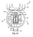
- Figure 14 is a schematic cross-sectional side view of the representative embodiment of Figure 1 , showing one aspect of the insertion and ejection cam components, with the fluid filter cartridge and the valve body in a first rotational position;
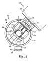
- Figure 15 is a schematic cross-sectional side view of the representative embodiment of Figure 1 , showing one aspect of the insertion and ejection cam components, with the fluid filter cartridge and the valve body in a second rotational position
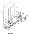
- Figure 16 is a perspective view of the fluid filter cartridge and spool valve manifold assembly shown with an optional mounting enclosure;
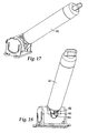
- Figure 17 is a perspective view of the fluid filter cartridge and spool valve manifold assembly shown with a representative keying system
- Figure 18 is a perspective view of the fluid filter cartridge and spool valve manifold assembly shown in Figure 17 showing the filter cartridge having a representative keying system about to be inserted into the spool valve manifold;
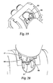
- Figure 19 is a partial perspective view of a representative fluid filter cartridge and spool valve manifold assembly having a representative keying system in the installed/operative position;
- Figure 20 is a partial perspective view of a representative fluid filter cartridge and spool valve manifold assembly having a representative keying system in the first rotational position prior to being installed in the operative position or being withdrawal from the operative position;
- Figure 21 is a partial perspective view of another representative fluid filter cartridge and spool valve manifold assembly having a representative keying system in the installed/operative position;
- Figure 22 is a partial perspective view of a representative fluid filter cartridge and spool valve manifold assembly having a representative optional inlet valve in the second rotational position prior to being installed;
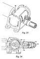
- Figure 23 is a partial perspective view of a representative fluid filter cartridge and spool valve manifold assembly having a representative optional inlet valve in the first rotational position after being installed;
- Figure 24 is a schematic cross-sectional side view of the representative embodiment of Figure 23 , showing one aspect of the optional inlet valve, with the fluid filter cartridge and the valve body in a first rotational position or the installed position;
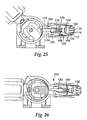
- Figure 25 is a schematic cross-sectional side view of the representative embodiment of Figure 23 , showing one aspect of the optional inlet valve, with the fluid filter cartridge and the valve body in a second rotational position or the uninstalled position;
- Figure 26 is a schematic cross-sectional side view of the representative embodiment of Figure 23 , showing a high pressure condition, with the fluid filter cartridge and the valve body in a first rotational position and the a poppet valve in the closed condition.
- the present disclosure overcomes several disadvantages associated with the prior art fluid filter systems.
- the advantages and other features of the fluid filter systems, comprising a representative manifold assembly and a representative replaceable fluid filter cartridge containing filter media, disclosed herein, will become more readily apparent to those having ordinary skill in the art from the following detailed description of the representative embodiments taken in conjunction with the drawings which set forth some representative embodiments of the present disclosure.
- FIG. 1-3 a representative fluid filter cartridge and a representative spool valve manifold assembly constructed in accordance with an exemplary, representative embodiment of the subject disclosure and designated generally by reference numeral 10.
- Filter cartridge and spool valve manifold assembly 10 includes a fluid filter cartridge 20 and a spool valve manifold 30. As will be explained below, filter cartridge and spool valve manifold assembly 10 is shown in Figures 1-3 in a first rotational position.
- filter cartridge 20 generally includes a representative sump 22 and a representative filter cover or inlet/outlet portion 24. As is known in the art, a filter element 23 (see Figure 9 ) is located within sump 22.
- the representative filter cartridge 20 may also include handle 28.
- Spool valve manifold 30 includes a representative valve housing 32 and a representative valve body 34. Valve body 34 rotates around axis a-a relative to valve housing 32. Spool valve manifold 30 is shown mounted within bracket 31 and this spool valve manifold/bracket subassembly will be referred to as mounted spool valve manifold 33. Valve housing 32 of spool valve manifold 30 may be snap mounted to bracket 31, although other assembly methods as known to persons of ordinary skill in the art could be used. Bracket 31 may be used to mount spool valve manifold 30 to the wall of an appliance (not shown) adjacent inlet and outlet ports of the fluid supply system (not shown). Valve housing 32 and bracket 31 typically remain stationary.
- representative seals 25 and 26 are located between inlet/outlet portion 24 and valve body 34 and representative seals 40, 42 and 44 are located between valve housing 32 and valve body 34.
- Tube connectors 50, 52 are used to connected spool valve manifold 30 to the fluid supply system.
- Other means of connecting tubing to the valve housing can be used such as the welded tubing attachment method that is disclosed in U S Patent No. 6,857,670 B2 .
- FIGs 5-7 show filter cartridge and spool valve manifold assembly 10 in a second rotational position.
- filter cartridge 20 rotates relative to bracket 31 in the direction of arrow A (around axis a-a of Figure 4 ) when moving from the first rotational position as illustrated in Figure 2 to the second rotational position as illustrated in Figure 6 .
- movement of filter cartridge 20 in the direction of arrow A may be accomplished by pulling on handle 28 in the direction of arrow B.
- movement of filter cartridge 20 in the direction of arrow A causes filter cartridge 20 to move in the direction of arrow C. Movement in the direction of arrow C is perpendicular to the direction of axis a-a. This is due to a camming action between filter cartridge 20 and cams 36 (best illustrated in Figure 4 ).
- filter cartridge 20 is operatively coupled to valve body 34.
- valve body 34 also rotates.
- cams 36 cause filter cartridge 20 to be ejected from valve body 34 and correspondingly from mounted spool valve manifold 33, thereby disconnecting filter cartridge 20 from spool valve manifold 30.
- Figure 8 shows filter cartridge 20 removed from mounted spool valve manifold 33.
- the angle through which filter cartridge 20 rotates relative to bracket 31 is approximately 45 degrees. This angle could be more or less than 45 degrees, with an angle of less than 90 degrees expected to be suitable for most applications, although an angle of more than 90 degrees would lie within the scope of the disclosure.
- one representative filter cartridge 20 has an inlet/outlet portion 24 at the top end thereof for the ingress and egress of fluid into interior chamber of filter cartridge 20 and into filter element 23.
- Filter element 23 may include any suitable filter media as is known in the art.
- Inlet/outlet portion 24 includes a representative cartridge outlet port 27 having a central through bore through which filtered fluid may exit filter cartridge 20.
- Cartridge outlet port 27 may be generally aligned with a central axis of filter cartridge 20.
- Circumferentially surrounding cartridge outlet port 27 are representative cartridge inlet ports 29, formed as arcuate through bores through which unfiltered fluid may enter filter cartridge 20.
- Inlet/outlet portion 24 is configured as a quick connect/disconnect fitting for mating with spool valve manifold 30.
- a person of ordinary skill in the art would appreciate that other inlet and outlet configurations lie within the scope of the disclosure.
- Cartridge inlet port 29 of inlet/outlet portion 24, as best illustrated in Figure 9 channels the incoming unfiltered fluid to the outer circumferential surface of filter element 23.
- the unfiltered fluid then travels radially inward through the filter media and is filtered in the process.
- the filtered fluid exits filter element 23 through cartridge outlet port 27.
- Inlet/outlet portion 24 and other portions of filter cartridge 20, such as sump 22, may be formed of any suitable material known to persons of ordinary skill in the art, including, but not limited to, for example, molded 20% talc-filled prolypropylene homopolymer or isoplast. Typically, a suitable material would be a standard National Standard Foundation (NSF) approved material.
- NSF National Standard Foundation
- Representative O-rings or other seals 25, 26 may be located around the outer circumference of cartridge inlet ports 29 and cartridge outlet ports 27. As best illustrated in Figure 10 , when filter cartridge 20 is installed in spool valve manifold 30, seals 25, 26 are located between inlet/outlet portion 24 and the complementary filter cartridge mounting surfaces 38 of spool valve manifold body 34. Seals 25, 26 isolate and prevent leakage between an unfiltered fluid flow path 60 and a filtered fluid flow path 62. Seals 25, 26 may be formed from nitrile rubber (NBR) or ethylene-propylene-diene rubber (EPDM) elastomers or other suitable materials known to persons of ordinary skill in the art.
- NBR nitrile rubber
- EPDM ethylene-propylene-diene rubber
- Figure 10 shows filter cartridge 20 inserted into valve body 34 of spool valve manifold 30 in the first rotational position.
- An opening 35 in the wall of valve housing 32 accommodates the insertion of filter cartridge 20 into valve body 34. Opening 35 is sized to accommodate the movement of filter cartridge 20 from the first rotational position to the second rotational position.
- cartridge inlet port 29 is in fluid communication with a housing inlet port 39 and cartridge outlet port 27 is in fluid communication with a housing outlet port 37.
- Unfiltered fluid from the fluid supply system (not shown) flows into housing inlet port 39 and into filter cartridge 20 via unfiltered fluid flow path 60 and cartridge inlet port 29. Filtered fluid flows from filter cartridge 20 and out through housing outlet port 37 to the fluid supply system (not shown) via cartridge outlet port 27 and filtered fluid flow path 62.
- a plug 54 may be provided to simplify the manufacture of valve body 34 and close off unfiltered fluid flow path 60 from the atmosphere, as would be understood by a person skilled in the molding manufacturing art.
- seals 40 and 42 isolate unfiltered fluid flow path 60 from filtered fluid flow path 62.
- seal 40 is located between valve housing 32 and valve body 34 and surrounds unfiltered fluid flow path 60 at this juncture.
- Seal 42 is located between valve housing 32 and valve body 34 and surrounds filtered fluid flow path 62 at this juncture. Seals 40 and 42 may be positioned within grooves as is known in the art.
- FIG 12 shows inlet/outlet portion 24 of filter cartridge 20 inserted into spool valve manifold 30 in the second rotational position.
- housing inlet port 39 is in fluid communication with a housing outlet port 37 without being in fluid communication with filter cartridge 20.
- Unfiltered fluid from the fluid supply system flows into housing inlet port 39 and out through housing outlet port 37 via bypass fluid flow path 64 (also shown in Figure 11 ).
- bypass fluid flow path 64 allows unfiltered fluid to flow directly to housing outlet port 37.
- seal 44 prevents bypass fluid flow path 64 from leaking to the atmosphere.
- seals 40 and 42 also prevent fluid from bypass fluid flow path 64 from entering unfiltered fluid flow path 60 and filtered fluid flow path 62.
- seal 44 also provides a secondary seal for unfiltered fluid flow path 60 and filtered fluid flow path 62 that prevents leakage to the atmosphere should either of seals 40 or 42 fail.
- seal 44 is located between valve housing 32 and valve body 34 and surrounds bypass fluid flow path 64. Seal 44 is also extended around unfiltered fluid flow path 60 and filtered fluid flow path 62. Seal 44 is shown positioned with a groove as is known in the art.
- seals 40, 42 and 44 may be formed from NBR or EPDM elastomers or other suitable materials known to persons of ordinary skill in the art.
- FIGs 14 and 15 show a representative filter cartridge 20 inserted into spool valve manifold 30 in the first rotational position and the second rotational position, respectively.
- Inlet/outlet portion 24 of filter cartridge 20 includes lug 21.
- Valve housing 32 includes insertion cam 48.
- Lug 21 and insertion cam 48 may be referred to as insertion cam components.
- Lug 21 interacts with insertion cam 48 when valve body 34 with filter cartridge inserted is rotated from the second rotational position (as illustrated in Figure 15 ) to the first rotational position (as illustrated in Figure 14 ).
- lug 21 rides on insertion cam 48 causing cartridge 20 to be advanced into and sealingly mated with valve body 34.
- FIG. 14 shows filter cartridge 20 fully seated within valve body 34
- Figure 15 shows filter cartridge 20 inserted into valve body 34, but not yet sealingly engaged with valve body 34.
- two lugs 21 are provided, one on each side of inlet/outlet portion 24.
- two insertion cams 48 are complementarily located on valve housing 32.
- a lug or other surface portion could be provided on valve housing 32 and a corresponding cam portion could be provided on filter cartridge 20.
- FIGs 14 and 15 also show the interaction between ejection cam 36 and a shoulder surface 46 of filter cartridge 20.
- Ejection cam 36 is provided on valve housing 32.
- Ejection cam 36 and shoulder surface 46 may be referred to as ejection cam components.
- ejection cam components When filter cartridge 20 is rotated from the first rotational position ( Figure 14 ) to the second rotational position ( Figure 15 ) the interaction between ejection cam 36 and shoulder surface 46 slidably ejects filter cartridge 20 in the direction of arrow C (see Figure 8 ) from valve body 34. This interaction breaks the seal between inlet/outlet portion 24 and valve body 34.
- a lug or surface portion could be provided on valve housing 32 and a corresponding cam portion could be provided on filter cartridge 20.
- Valve housing 32, valve body 34 and bracket 31 may be formed of any suitable materials known to persons of ordinary skill in the art, including, but not limited to, isoplast or molded polypropylene. Bracket 31 may also be formed from glass-filled prolypropylene or other reinforced plastics for additional strength.
- a representative optional handle 28 is shown provided on filter cartridge 20 at an end opposite to the inlet/outlet portion 24 of filter cartridge 20.
- Handle 28 may be grasped by a user to assist in rotating filter cartridge 20 from the first rotational position to the second rotational position, and vice versa, and also for slidingly removing the disengaged filter cartridge from mounted spool valve manifold assembly 33.
- Handle 28 because of its position at the far end of filter cartridge 20, reduces the force required to break the sealing engagement between filter cartridge 20 and valve body 34.
- a handle or other means of grasping filter cartridge 20 could be located at other positions along the length of filter cartridge 20 and still provide a mechanical advantage for overcoming any compression set of the seals.
- an enclosure 70 for filter cartridge and spool valve manifold assembly 10 is shown.
- Enclosure 70 may be mounted to a wall or a door of an appliance or other device.
- Enclosure 70 includes a door 72 rotationally mounted to box 74 in the vicinity of mounted spool valve manifold assembly 33.
- a handle 76 is provided on one side of door 72 and one or more brackets 78 are provided on the other side of door 72.
- Brackets 78 are sized to slidably accommodate filter cartridge 20.
- a user would open door 72 as illustrated in Figure 16 and slidably insert filter cartridge 20 into brackets 78 such that lug 21 of filter cartridge 20 is positioned within valve housing 32 and inlet/outlet portion 24 is positioned with valve body.
- housing inlet port 39 is in fluid communication with housing outlet port 37 via bypass fluid flow path 64.
- filter cartridge 20 is slidably driven into sealing engagement with valve body 34 by the interaction of lug 21 with insertion cam 48 as filter cartridge 20 is rotated into the first rotational position.
- housing inlet port 39 is in fluid communication with cartridge inlet port 29 via fluid flow path 60 and housing outlet port 37 is in fluid communication with cartridge outlet port 27 via fluid flow path 62, thereby allowing fluid from the fluid supply system to be filtered through filter cartridge 20.
- door 72 is rotated open, thereby slidably driving filter cartridge 20 away from valve body 34 and breaking the sealing engagement of filter cartridge 20 with valve body 34 by the interaction of shoulder surface 46 and ejection cam 36.
- the mounted spool valve manifold assembly 33 can easily be mounted in any orientation and location in or on an appliance or other appropriate device, as would be understood by those skilled in the art. This allows manufactures, such as, for example, appliance manufactures multiple configurations to best suit their application without the need for costly changes to the filter system.
- the filter cartridge 20 and the spool valve manifold interface each include complimentary key structures.
- Such complimentary key structures are specifically designed so that only specific type of filter cartridge having the one specific complimentary key structure pattern, out of a plurality of possible key complimentary structure pattern(s) available for such use, can be installed in the spool valve manifold interface(s) having the matching specific complimentary key structure.
- One representative system includes a keying system achieved by a mechanical system, as illustrated in Figures 17-21 , where the various keying features of the filter cartridge have to align and mate correctly with various keying features on the spool valve manifold interface located on the spool valve manifold, the keying features being selected from any operable combination of a plurality of sizes, shapes and locations and combinations thereof with respect to protrusions and depressions formed on the filter cartridge 20 and the spool valve manifold 30, as would be known to those skilled in the art.
- Mechanical keying systems such as those disclosed in US Patent Nos. 6,458,269 and 6,949,189 B2 , entitled Keyed Filter Assembly, owned by the assignee of the present application disclose exemplary approaches that are similar to and could be applicable to possible specific embodiments of the present disclosure.
- FIG. 17-21 One representative mechanical keying system 80 is illustrated in Figures 17-21 . These Figures illustrate the basic principle of the concept and are not intended to disclose all possible combinations of the plurality of various of protrusions and depressions and other operable combinations that can be formed in the interfacing component of the cartridge and in the corresponding receiving component of the spool valve manifold, as would be understood by those skilled in the art.
- Figures 17, 18 and 20 illustrate the concept and in the lining up of the keying structures 82, 84 that have been formed on an appropriate component of the filter cartridge and the spool valve manifold respectively.
- a relatively larger protrusion 86 is formed on one side of the filter cartridge neck 88 and a relatively smaller protrusion 90 is formed on the other side of the filter cartridge neck 88 and complementary sized depressions or cut-outs 91, 92 are formed on the corresponding portion of the spool valve manifold ( Figures 19 and 20 ) such that, when the lug 21 is inserted into the insertion cam 48, the filter cartridge is operatively inserted into the spool valve manifold, as best illustrated in Figures 19 and 21 .
- Keying systems that perform the selective interfacing function can also be obtained through the use of other non-mechanical technologies such as, but not limited to, RFID tags, magnetic readers and bar code readers and other operative systems known in the art.
- electronics would be used to control the activation of the solenoid valves that are used to control the flow of water from the filter cartridge to the end appliance or dispenser, as evidenced by the disclosure contained in US Patent Application Publication No. US 2006/0060512 A1 , entitled, System For Monitoring the Performance of Fluid Treatment Cartridges, published March 23, 2006.
- One possible optional inlet component that can be incorporated into the manifold assembly of the present disclosure provides a mechanism for converting the system to a "shut-off' style system when a filter cartridge is not installed in the spool valve manifold.
- This optional component (a modified inlet) utilizes a poppet valve that is controlled by a cam surface on the valve spool valve manifold. When the spool valve manifold is turned to the filter cartridge un-install position, the poppet valve will close thus arresting the flow of fluid though the spool valve manifold. When the spool valve manifold is turned to the filter mode position (filter installed position), the poppet valve will be forced open to allow fluid to flow through the spool valve manifold and into the filter cartridge.
- the modified inlet assembly 100 is configured as a "floating" assembly.
- the floating assembly is spring loaded such that, as internal pressure in the filter cartridge and the spool valve manifold increase, the inlet subassembly will start to push away from the spool valve manifold and the poppet valve will start to close. Once a predetermined pressure is reached at the inlet, the inlet subassembly will be pushed away from the spool valve manifold a distance sufficient for the poppet valve to seat (close) and thus shutoff the fluid flow into the spool valve manifold and subsequently into the filter cartridge.
- the spool valve manifold 30 component of the liquid filter cartridge and spool valve manifold assembly 10, presently preferably, comprises three sections; those being the inlet assembly 100, the filter interconnect structure 102 and the outlet assembly 104.
- the inter-relationship of these three sub-components controls the flow of fluid, presently preferably, water into and out of the filter cartridge 20.
- the inlet assembly 100 is a sprung element.
- sprung element we mean that, as the filter cartridge 20 is installed into and removed from the manifold assembly 30, the inlet assembly 100 will traverse up and down with the movement of the filter cartridge neck or stem 88.
- the spool valve manifold inlet assembly 30 comprises a representative outlet assembly 102; a representative inlet assembly 100, a representative inlet return spring 106 and a representative inlet return stop 108.
- one presently preferred embodiment of the inlet assembly 100 comprises a representative inlet 110, a representative inlet connector 112, a representative poppet valve 114, a representative poppet valve spring 116, a representative collet 118 a representative collet retainer 120, and representative sealing structure or o-rings 122.
- Inlet assembly 100 comprises a head interface section 123, for interfacing with the filter interconnect structure (Head) 124, and comprises inlet connector 112 for receiving sealing structure, such as, for example, an o-ring 125, operatively positioned therein, an inlet poppet valve 114 having a spring operatively positioned thereon for biasing the poppet valve 114 toward the filter cartridge 20, when a filter cartridge is positioned in the liquid filtration system is operatively positioned in the spool valve manifold assembly 10.
- sealing structure such as, for example, an o-ring 125
- an inlet return spring 106 is provided and operatively interfaces with the inlet assembly 100, as will be described in more detail below.
- the inlet assembly 100 Since the inlet assembly 100 is a sprung element, the inlet assembly 100 will also traverse up and down due to fluid pressure when the cartridge is installed in the manifold assembly 30. Specifically, the poppet value 114 is always engaged with the filter cartridge poppet interface 126 when the filter cartridge is installed and the poppet valve 114 is biased in the open position. However, as the fluid pressure of the liquid filtration system (not shown) is increased, the inlet assembly 100 will start to move up and away from the filter cartridge 20. As the liquid pressure increase is continued, the inlet assembly 100 will move far enough away from the filter cartridge 20 that the poppet valve 114 will close, thus shutting off the inlet liquid pressure, as illustrated in Figure 26 .
- the inlet 110 of the present disclosure were not allowed to move/translate/float, the column of water that is trapped between the filter O-rings would not be able to translate and would have to be compressed. If these columns of water were required to compress in order to effectuate filter translation, as the filter cartridge is pushed forward during un-install, the force to compress the water that is trapped between the filter O-rings would be extremely high due to hydraulic pressure required to compress water.
- the benefits derived from the optional "floating" inlet have been found to be quite desirable to the successful operation of this particular representative embodiment of the present disclosure. While we have illustrated the inlet as the "floating" component, it should be understood that the outlet or other valve sub assembly that enables water to be displaced without compressing the water could also be utilized as the "floating" component.
- This phenomenon of the inlet assembly 100 floating according to the amount of fluid pressure in the system transforms the system of the present disclosure into an automatic liquid shut-off system.
- the liquid pressure increases past a selected, predetermined desired maximum operating system pressure
- the poppet valve 114 will be closed thereby closing the poppet valve inlet 130 and automatically shutting-off liquid flow to the filter cartridge 20 by the movement of the inlet assembly 100 away from the filter cartridge 20.
- the poppet valve inlet 130 will open, see Fig. 24 , thereby allowing the fluid to flow into and through the filter cartridge 20 exiting the liquid filtration system via the outlet 110, as illustrated in Fig. 24 .
- the liquid filtration system (not shown) and utilized with the present disclosure is capable of automatically controlling the operating pressure limits, some unique system safety features directly result therefrom. For example, if the liquid filtration system were to experience a water spike (i.e. water hammer) or high pressure, the downstream components of the inlet assembly (i.e. head, bracket, filter cartridge, outlet assembly, etc) would not be subjected to this water spike or high pressure, greater than about 100psi (7 bar). Specifically, as the illustrated in Figure 26 , the inlet assembly 132 has moved more distant from the poppet valve 114, as compared to Figure 25 , thereby moving the poppet valve seat out of contact with the spool valve manifold 10 and thus preventing the flow of liquid into or out of filter cartridge.
- a water spike i.e. water hammer
- the downstream components of the inlet assembly i.e. head, bracket, filter cartridge, outlet assembly, etc
- the inlet assembly 132 has moved more distant from the poppet valve 114, as compared to Figure
- downstream components of the manifold assembly 30 and filter cartridge 20 do not need to be constructed to withstand such high pressure events. Not being required to construct the down stream components to withstand such a high pressure would enable the liquid filtration system manufacturer to realize a significant cost savings in the types of material that need to be used and the strength of those materials used.
- Fluid filter systems, manufactured in accordance with the present disclosure could now be built with lower price commodity materials and relatively thin wall sections, as compared to the materials and wall thickness now common in such systems. Utilization of lower price commodity materials and relatively thin wall sections would dramatically reduce the cost of each component from a material cost and a manufacturing cost perspective.
- shut-off pressures are controlled by the inlet return/compression spring 106 and by changing the characteristics of this inlet return/compression spring 106 the opening pressure and the shutoff pressure can be varied, in accordance with known principles.
- the poppet valve 114 of the inlet assembly 100 has the ability to shutoff flow at high pressures and reset itself or return to normal flow operation once the pressure level falls back below a predetermined maximum limit.
- This predetermined maximum limit can be simply modified by adjusting the strength of the inlet return spring, as would be known to those skilled in the art.
- fluid filtration system comprising a fluid filtration assembly and a replaceable fluid filter cartridge containing filter media
- the fluid filtration assembly having the capability for facilitating the removal of a first replaceable fluid filter cartridge and then having the capability for facilitating the installation of another replaceable fluid filter cartridge therein in a fluid supply system and, in particular, to the spool valve manifold assembly that facilitates the quick and easy removal and installation of the replaceable fluid filter cartridges from and into the fluid filtration assembly as defined in the following claims.
Landscapes
- Chemical & Material Sciences (AREA)
- Chemical Kinetics & Catalysis (AREA)
- Engineering & Computer Science (AREA)
- General Engineering & Computer Science (AREA)
- Organic Chemistry (AREA)
- Water Supply & Treatment (AREA)
- Hydrology & Water Resources (AREA)
- Environmental & Geological Engineering (AREA)
- Life Sciences & Earth Sciences (AREA)
- Mechanical Engineering (AREA)
- Health & Medical Sciences (AREA)
- Clinical Laboratory Science (AREA)
- Multiple-Way Valves (AREA)
- Details Of Valves (AREA)
- Mechanically-Actuated Valves (AREA)
- Lubrication Details And Ventilation Of Internal Combustion Engines (AREA)
- Separation Using Semi-Permeable Membranes (AREA)
- Sliding Valves (AREA)
Applications Claiming Priority (2)
| Application Number | Priority Date | Filing Date | Title |
|---|---|---|---|
| US68164905P | 2005-05-16 | 2005-05-16 | |
| PCT/US2006/018929 WO2006124906A1 (en) | 2005-05-16 | 2006-05-16 | Spool valve manifold interconnect for a filter system |
Publications (2)
| Publication Number | Publication Date |
|---|---|
| EP1888199A1 EP1888199A1 (en) | 2008-02-20 |
| EP1888199B1 true EP1888199B1 (en) | 2012-09-12 |
Family
ID=36972762
Family Applications (1)
| Application Number | Title | Priority Date | Filing Date |
|---|---|---|---|
| EP20060784421 Active EP1888199B1 (en) | 2005-05-16 | 2006-05-16 | Spool valve manifold interconnect for a filter system |
Country Status (9)
| Country | Link |
|---|---|
| US (6) | US8097158B2 (zh) |
| EP (1) | EP1888199B1 (zh) |
| JP (1) | JP5001936B2 (zh) |
| KR (1) | KR101315573B1 (zh) |
| CN (1) | CN101198390B (zh) |
| AU (1) | AU2006247365A1 (zh) |
| BR (1) | BRPI0610315A2 (zh) |
| MX (1) | MX2007014452A (zh) |
| WO (1) | WO2006124906A1 (zh) |
Families Citing this family (76)
| Publication number | Priority date | Publication date | Assignee | Title |
|---|---|---|---|---|
| US7086539B2 (en) | 2002-10-21 | 2006-08-08 | Adc Telecommunications, Inc. | High density panel with rotating tray |
| EP1888199B1 (en) | 2005-05-16 | 2012-09-12 | 3M Innovative Properties Company | Spool valve manifold interconnect for a filter system |
| US7651070B2 (en) * | 2006-01-19 | 2010-01-26 | Clean & Clear Corporation | Canter element controlled combination manifold, valve and filter module system |
| US7992667B2 (en) * | 2006-08-08 | 2011-08-09 | David Wayne Rennie | Oil cooling and filtering system, kit and apparatus |
| EP2190788B1 (en) * | 2007-09-05 | 2016-12-07 | Helen of Troy Limited (Barbados) | Faucet-mounted water filtration system |
| DE102008002727B4 (de) * | 2008-06-27 | 2020-12-17 | Brita Gmbh | Vorrichtung zur Behandlung von Wasser, insbesondere Filtervorrichtung, und Kartusche |
| EP2355914B1 (en) * | 2008-09-05 | 2014-06-11 | 3M Innovative Properties Company | Filtration system |
| JP2010096410A (ja) * | 2008-10-16 | 2010-04-30 | Sharp Corp | 冷蔵庫 |
| US8302422B2 (en) * | 2009-10-07 | 2012-11-06 | General Electric Company | Refrigerator with treated water system |
| US8627675B2 (en) | 2010-02-01 | 2014-01-14 | Whhirlpool Corporation | Lever design version of “push button” filter |
| KR101164159B1 (ko) | 2010-03-11 | 2012-07-11 | 웅진코웨이주식회사 | 정수필터 조립모듈 |
| US9157399B2 (en) * | 2011-05-05 | 2015-10-13 | Hamilton Sundstrand Corporation | Fuel filter adapter |
| US8955349B2 (en) * | 2011-05-09 | 2015-02-17 | General Electric Company | Water filter assembly |
| US8844307B2 (en) | 2011-06-06 | 2014-09-30 | General Electric Company | Appliance with a water filtration system |
| US8845896B2 (en) | 2011-09-15 | 2014-09-30 | Whirlpool Corporation | Water filter system |
| US9199202B2 (en) * | 2011-09-15 | 2015-12-01 | Sartorius Stedim Biotech Gmbh | Filter element attachment, filter cartridge, and filter system |
| US8945383B2 (en) * | 2012-03-16 | 2015-02-03 | Kx Technologies Llc | Filtration system |
| JP2013230410A (ja) * | 2012-04-27 | 2013-11-14 | Sharp Corp | 液体濾過器 |
| US20140042073A1 (en) * | 2012-08-10 | 2014-02-13 | Whirlpool Corporation | Liquid filter housing with handles |
| US9314716B2 (en) * | 2012-11-12 | 2016-04-19 | Whirlpool Corporation | Customizable multi-stage water treatment assembly |
| US9327216B2 (en) | 2012-11-12 | 2016-05-03 | Whirlpool Corporation | Customizable multi-stage water treatment system |
| USD752707S1 (en) * | 2013-05-31 | 2016-03-29 | Kx Technologies Llc | Filter cartridge with handle end |
| USD753788S1 (en) * | 2013-05-31 | 2016-04-12 | Kx Technologies Llc | Handle end of filter cartridge |
| EP3013446B1 (en) | 2013-06-26 | 2021-12-08 | Pentair Residential Filtration, LLC | Filter cartridge and water filtration system |
| USD755344S1 (en) | 2014-06-26 | 2016-05-03 | Pentair Residential Filtration, Llc | Filter cartridge |
| USD752179S1 (en) * | 2014-09-05 | 2016-03-22 | Red Origen, LLC | Interchangeable water filter base or portions thereof |
| US9393507B2 (en) | 2014-11-14 | 2016-07-19 | General Electric Company | Water filter audible position indicator |
| US20160199856A1 (en) * | 2015-01-12 | 2016-07-14 | Pentair Flow Technologies, Llc | Variable Flow Nozzle System and Method |
| CN205598746U (zh) * | 2015-04-09 | 2016-09-28 | 碧然德有限公司 | 用于形成液体处理设备的装置、液体处理设备以及液体处理芯 |
| CN107613816B (zh) | 2015-05-27 | 2021-02-05 | 流量控制有限责任公司 | 筒泵 |
| US20170095757A1 (en) | 2015-05-27 | 2017-04-06 | Flow Control LLC | Cartridge Accumulator |
| EP3666358A1 (en) * | 2015-08-14 | 2020-06-17 | 3M Innovative Properties Co. | Identification of filter media within a filtration system |
| US10071326B2 (en) * | 2015-09-11 | 2018-09-11 | 3M Innovative Properties Inc. | Filter cartridge for translational insertion and rotational engagement of a manifold |
| CN116943431A (zh) | 2015-09-14 | 2023-10-27 | 流量控制有限责任公司 | 积储器筒 |
| KR101902059B1 (ko) | 2016-06-07 | 2018-09-27 | 엘지전자 주식회사 | 외장형 정수 필터 케이스, 그 설치 구조 및 이를 활용한 살균 방법 |
| KR20190041013A (ko) * | 2016-09-08 | 2019-04-19 | 쓰리엠 이노베이티브 프로퍼티즈 컴파니 | 정수 카트리지 |
| CN106673135B (zh) * | 2016-12-08 | 2023-05-02 | 厦门唯科健康产业有限公司 | 一种家用净水器 |
| GB201701108D0 (en) | 2017-01-23 | 2017-03-08 | Parker Hannifin Mfg (Uk) Ltd | A filter assembly |
| GB201701107D0 (en) | 2017-01-23 | 2017-03-08 | Parker Hannifin Mfg (Uk) Ltd | A filter assembly |
| US10525387B2 (en) | 2017-04-06 | 2020-01-07 | Whirlpool Corporation | Filter cartridge |
| CA3056504C (en) * | 2017-07-25 | 2021-05-11 | Condair Ltd. | Field replaceable fluid element methods and systems for fluidic processors |
| US11428357B2 (en) | 2017-07-25 | 2022-08-30 | Condair Ltd. | Field replaceable fluid element methods and systems for fluidic processors |
| US10584040B2 (en) | 2017-10-06 | 2020-03-10 | Whirlpool Corporation | Filter cartridge |
| KR101976641B1 (ko) * | 2018-02-26 | 2019-05-09 | 오비오주식회사 | 정수장치용 필터헤드 |
| WO2019165517A1 (en) * | 2018-03-02 | 2019-09-06 | Electrolux Do Brasil S.A. | Water circuit assembly for a refrigerator |
| WO2019196862A1 (zh) * | 2018-04-10 | 2019-10-17 | 艾欧史密斯(中国)热水器有限公司 | 滤芯组件更换结构、滤芯壳体安装机构及净水器、净水装置 |
| CN110354559A (zh) * | 2018-04-10 | 2019-10-22 | 艾欧史密斯(中国)热水器有限公司 | 滤芯组件更换结构及其净水器 |
| CN108644425B (zh) * | 2018-06-26 | 2019-10-29 | 浙江沁园水处理科技有限公司 | 一种带有减压模块的进水阀及其净水器 |
| BE1026438B1 (nl) * | 2018-06-26 | 2020-02-04 | Atlas Copco Airpower Nv | Filterinrichting en werkwijze voor uit- en/of inschakelen van zulke filterinrichting |
| EP3813979A4 (en) * | 2018-06-27 | 2022-03-23 | KX Technologies LLC | FILTER CONNECTION WITH CORRELATED MAGNETIC TORQUE DESIGN |
| CN110732179B (zh) * | 2018-07-20 | 2023-12-01 | 魏斯瓦瑟环境技术(嘉兴)有限公司 | 净水系统、接口装置及其方法 |
| US10807025B2 (en) | 2018-08-06 | 2020-10-20 | Whirlpool Corporation | Blind attachment interface for filter housing assembly |
| CN110812934A (zh) * | 2018-08-07 | 2020-02-21 | 天津市天创百纯环保科技有限公司 | 一种带旋转内芯驱动顶针开合水路的过滤系统 |
| US11992790B2 (en) * | 2018-08-07 | 2024-05-28 | Tianjin Tianchuang Best Pure Environmental Science And Technology Co., Ltd. | Filtration system with rotating core driving thimble opening and closing water passage |
| CN109499132A (zh) * | 2018-11-15 | 2019-03-22 | 厦门百霖净水科技有限公司 | 一种净水过滤芯结构 |
| DE102018129752A1 (de) * | 2018-11-26 | 2020-05-28 | Franke Technology And Trademark Ltd | Filtervorrichtung zur trinkwasserfilterung |
| KR20200074500A (ko) * | 2018-12-17 | 2020-06-25 | 삼성전자주식회사 | 냉장고 |
| CN109795885B (zh) * | 2019-03-22 | 2024-03-22 | 杭州回水科技股份有限公司 | 一种带保护套管的气力输送装置及其使用方法 |
| JP7406550B2 (ja) * | 2019-04-23 | 2023-12-27 | ヤマシンフィルタ株式会社 | フィルタ装置 |
| CN113853247B (zh) * | 2019-05-17 | 2023-04-21 | Kx技术有限公司 | 利用相关磁性致动实现下游系统功能的过滤器互连 |
| US11338227B2 (en) | 2019-08-01 | 2022-05-24 | Pall Corporation | Manifold assembly and method of use |
| US11326379B2 (en) * | 2019-08-28 | 2022-05-10 | Kx Technologies Llc | Filter interconnects utilizing magnetic shear force generated by coded polymagnets |
| CN110585787A (zh) * | 2019-10-22 | 2019-12-20 | 佛山市麦克罗美的滤芯设备制造有限公司 | 滤芯安装结构及过滤装置 |
| CA3156557A1 (en) * | 2019-11-18 | 2021-05-27 | Robert Astle | Push filter with floating key lock |
| USD947319S1 (en) * | 2020-03-10 | 2022-03-29 | Xiaoping Huang | Filter element |
| KR102287193B1 (ko) * | 2020-03-24 | 2021-08-06 | 주식회사 마이크로필터 | 필터 유닛 및 이를 포함하는 냉장고 |
| USD987772S1 (en) | 2020-07-02 | 2023-05-30 | Qingdao Ecopure Filter Co., Ltd. | Water filter |
| CA3216779A1 (en) | 2021-04-30 | 2022-11-03 | Whirlpool Corporation | Filter assembly |
| USD1001236S1 (en) | 2021-05-28 | 2023-10-10 | Electrolux Home Products, Inc. | Filter cartridge |
| US11779867B2 (en) | 2021-05-28 | 2023-10-10 | Electrolux Home Products, Inc. | Mechanical interlock system for a filter |
| US11872510B2 (en) | 2021-07-01 | 2024-01-16 | Qingdao Ecopure Filter Co., Ltd | Water filter |
| USD1019884S1 (en) | 2021-08-03 | 2024-03-26 | Qingdao Ecopure Filter Co., Ltd. | Water filter |
| USD1016970S1 (en) | 2021-09-03 | 2024-03-05 | Qingdao Ecopure Filter Co., Ltd | Water filter |
| US11820673B2 (en) * | 2021-10-19 | 2023-11-21 | Kemflo International Co., Ltd. | Water purifier with leakproof function |
| WO2024102918A1 (en) | 2022-11-09 | 2024-05-16 | Electrolux Home Products, Inc. | Cartridge and method for cleaning water lines of an appliance |
| WO2024102914A1 (en) | 2022-11-09 | 2024-05-16 | Electrolux Home Products, Inc. | Reusable water filter cartridge |
Family Cites Families (73)
| Publication number | Priority date | Publication date | Assignee | Title |
|---|---|---|---|---|
| US1688326A (en) | 1925-09-16 | 1928-10-23 | Zenith Carburateur Soc Du | Filter |
| US2857128A (en) * | 1956-10-18 | 1958-10-21 | Stern Daniel | Safety shutoff coupling |
| US3399776A (en) | 1965-09-02 | 1968-09-03 | Robert R. Knuth | Detachable snap-on filter for a hydraulic system |
| JPS5129619Y1 (zh) * | 1969-03-15 | 1976-07-26 | ||
| FR2808457B1 (fr) * | 2000-05-02 | 2002-07-19 | Rena Sa | Filtre exterieur a un bac, notamment a un aquarium |
| US3742970A (en) * | 1970-02-13 | 1973-07-03 | Pall Corp | Flow-sensitive sensing and shut-off device |
| US3643692A (en) * | 1970-09-28 | 1972-02-22 | Paul L Traylor | Valve |
| US3684100A (en) | 1971-04-05 | 1972-08-15 | Sam Close | Filter assembly and disposable filter element therefor |
| CH537546A (de) * | 1971-04-06 | 1973-05-31 | Saffin Von Corpon Paul | Robinet mélangeur |
| BE791684A (fr) | 1971-11-22 | 1973-03-16 | Ogden Hubert S | Cartouche filtrante amovible |
| JPS5129619A (en) | 1974-09-02 | 1976-03-13 | Matsushita Electric Ind Co Ltd | Nainenkikanno haikigasujokasochi |
| US3926187A (en) * | 1974-12-19 | 1975-12-16 | Jose J Iglesias | Urological bladder evacuator |
| US4108207A (en) * | 1977-04-13 | 1978-08-22 | The United States Of America As Represented By The United States Department Of Energy | Multiple-port valve |
| JPS57184408A (en) * | 1981-05-08 | 1982-11-13 | Jidosha Denki Kogyo Co Ltd | Filter for fuel tank |
| DE3126507A1 (de) | 1981-07-04 | 1983-01-20 | Surculus AG, Vaduz | "armatur" |
| JPS5867510A (ja) | 1981-10-20 | 1983-04-22 | Nippon Denso Co Ltd | 自動車用換気装置 |
| JPS5867510U (ja) * | 1981-10-30 | 1983-05-09 | 三菱農機株式会社 | オイルフイルタ−の取付け構造 |
| US4469131A (en) * | 1982-07-12 | 1984-09-04 | Traylor Paul L | Spool valve |
| DE3520139A1 (de) | 1985-06-05 | 1986-12-11 | Joachim 7252 Weil der Stadt Wolf | Filtervorrichtung |
| DE3640531C1 (de) | 1986-11-27 | 1987-09-03 | Bayerische Motoren Werke Ag | Filteranordnung zum Reinigen von fluessigen Betriebsstoffen,insbesondere des Schmieroeles von Brennkraftmaschinen |
| US4806240A (en) * | 1987-06-12 | 1989-02-21 | Cuno, Incorporated | Adapter and cartridge assembly |
| US4979530A (en) | 1987-12-24 | 1990-12-25 | Ameri-Can Brass Faucet Inc. | Modular valve assembly |
| GB2216030B (en) | 1988-05-11 | 1991-10-09 | Joachim Wolf | A filter |
| GB2216028B (en) | 1988-05-16 | 1991-09-25 | Joachim Wolf | A filter manifold |
| IL87280A (en) * | 1988-08-01 | 1991-01-31 | Dolev Moshe | Quick-disconnect hose coupling device |
| US4857189A (en) * | 1988-10-13 | 1989-08-15 | Everpure, Inc. | Filter cartridge with a lugged concentric closure portion |
| US5152321A (en) * | 1991-10-07 | 1992-10-06 | Ecowater Systems, Inc. | Bypass valve |
| DE4135867A1 (de) * | 1991-10-31 | 1993-05-06 | Alfred Teves Gmbh, 6000 Frankfurt, De | Manschettenrueckschlagventil |
| US5230812A (en) | 1992-07-29 | 1993-07-27 | Williams Richard T | Pressure vessel |
| US5461948A (en) | 1992-08-27 | 1995-10-31 | Perrero, Jr.; Thomas | Socket type tool for removing oil filter cartridge |
| US5336406A (en) * | 1993-01-26 | 1994-08-09 | Elkay Manufacturing Company | Replaceable filter cartridge and head assembly with safety shut-off valve |
| US5389260A (en) | 1993-04-02 | 1995-02-14 | Clack Corporation | Brine seal for tubular filter |
| US5397462A (en) * | 1993-08-24 | 1995-03-14 | Matsushita Electric Industrial Co., Ltd. | Filter with laterally removable element and valve means |
| US5445734A (en) | 1994-11-18 | 1995-08-29 | Chen; Ching-Wen | Water filter |
| US5685985A (en) * | 1995-12-20 | 1997-11-11 | Baldwin Filters, Inc. | Environmentally friendly filter cartridge |
| US5762788A (en) * | 1996-08-12 | 1998-06-09 | Caterpillar Inc. | Fluid filter having a reusable filter housing and a replaceable coreless filter element |
| US5882511A (en) | 1996-10-30 | 1999-03-16 | Fil-Tech Corporation | Filter apparatus with coupling and latch mechanism |
| US5876599A (en) * | 1997-04-07 | 1999-03-02 | Kuss Corporation | Compact in-tank fuel filter and module |
| US5919362A (en) | 1997-04-28 | 1999-07-06 | Cuno, Inc. | Expandable encapsulated filter cartridge assembly |
| US5931196A (en) * | 1998-04-29 | 1999-08-03 | United States Filter Corporation | Bypass valve |
| ES2345252T3 (es) * | 1998-10-09 | 2010-09-20 | Entegris, Inc. | Modulo de filtracion. |
| US6579455B1 (en) | 1999-09-09 | 2003-06-17 | Pti Advanced Filtration | Filter and valve apparatus |
| US6953526B1 (en) | 2000-03-22 | 2005-10-11 | Cuno Incorporated | Filter assembly |
| US6458269B1 (en) | 2000-04-20 | 2002-10-01 | Cuno Incorporated | Keyed filter assembly |
| US7407148B2 (en) | 2000-04-20 | 2008-08-05 | 3M Innovative Properties Company | Rotary valve assembly for fluid filtration system |
| US6949189B2 (en) | 2000-04-20 | 2005-09-27 | Cuno Incorporated | Keyed filter assembly |
| US6457698B2 (en) | 2000-06-16 | 2002-10-01 | United States Filter Corporation | Bypass valve |
| JP3514724B2 (ja) * | 2000-11-29 | 2004-03-31 | 日東工器株式会社 | 管継手 |
| ITPD20010179A1 (it) * | 2001-07-17 | 2003-01-17 | Askoll Holding Srl | Gruppo di raccordo tubi con blocco di sicurezza per filtri esterni per acquari. |
| US6632355B2 (en) | 2001-07-30 | 2003-10-14 | Pentapure Incorporated | Low spillage replaceable water filter assembly |
| US20030019819A1 (en) | 2001-07-30 | 2003-01-30 | Karl Fritze | Hot disconnect replaceable water filter assembly |
| US6857670B2 (en) | 2001-12-05 | 2005-02-22 | Cuno Incorporated | Plastic tube joint |
| US7638042B2 (en) | 2002-02-15 | 2009-12-29 | 3M Innovative Properties Company | System for monitoring the performance of fluid treatment cartridges |
| US6740235B2 (en) * | 2002-03-04 | 2004-05-25 | Culligan International Company | Swivelling filter head assembly |
| KR100494591B1 (ko) * | 2002-08-28 | 2005-06-10 | 웅진코웨이주식회사 | 정수기의 필터 장치 |
| KR100462231B1 (ko) * | 2002-10-30 | 2004-12-17 | 웅진코웨이주식회사 | 정수기의 필터 장치 |
| JP3829117B2 (ja) * | 2002-12-27 | 2006-10-04 | 日東工器株式会社 | 管継手 |
| US7147773B2 (en) | 2003-04-25 | 2006-12-12 | Whirlpool Corporation | Refrigerator with treated water |
| US7000894B2 (en) | 2003-04-25 | 2006-02-21 | Pur Water Purification Products, Inc. | Fluidic cartridges and end pieces thereof |
| US20040232064A1 (en) * | 2003-05-23 | 2004-11-25 | James Wilkinson | Cartridge filters and housing connections therefor |
| EP1648580A4 (en) * | 2003-07-29 | 2007-07-25 | 3M Innovative Properties Co | WATER FILTER ADAPTER WITH LATCH |
| US20050167352A1 (en) * | 2004-02-03 | 2005-08-04 | Oasis Corporation | Filter cartridge and manifold for a water purification system |
| US20060032806A1 (en) | 2004-08-16 | 2006-02-16 | Parker Mark A | Apparatus to filter water |
| KR200384557Y1 (ko) * | 2005-02-28 | 2005-05-16 | 주식회사 피코그램 | 정수장치의 필터 장착구조 |
| EP1888199B1 (en) | 2005-05-16 | 2012-09-12 | 3M Innovative Properties Company | Spool valve manifold interconnect for a filter system |
| US7261815B2 (en) * | 2005-10-12 | 2007-08-28 | Whirlpool Corporation | Water filter for refrigerator water dispenser |
| US7651070B2 (en) | 2006-01-19 | 2010-01-26 | Clean & Clear Corporation | Canter element controlled combination manifold, valve and filter module system |
| KR100772889B1 (ko) | 2006-04-18 | 2007-11-02 | 주식회사 위닉스 | 정수필터, 정수필터 어셈블리 연결구 및 이들이 설치된정수장치 |
| US20080000820A1 (en) | 2006-06-30 | 2008-01-03 | Mitchell Alan J | Water Filter Cartridge and Valve with Autobypass Feature |
| US20080156711A1 (en) | 2006-12-29 | 2008-07-03 | Vitan Craig R | Water filter assembly and filter cartridge for use therewith |
| KR100870572B1 (ko) | 2007-02-28 | 2008-11-27 | 주식회사 영우워터라인 | 회동형 커넥터를 가지는 정수기용 필터 어셈블리 |
| KR100930665B1 (ko) * | 2008-01-28 | 2009-12-09 | 앨트웰텍 주식회사 | 회전착탈형 필터서포터 |
| EP2355914B1 (en) | 2008-09-05 | 2014-06-11 | 3M Innovative Properties Company | Filtration system |
-
2006
- 2006-05-16 EP EP20060784421 patent/EP1888199B1/en active Active
- 2006-05-16 US US11/435,676 patent/US8097158B2/en active Active
- 2006-05-16 MX MX2007014452A patent/MX2007014452A/es not_active Application Discontinuation
- 2006-05-16 KR KR1020077027437A patent/KR101315573B1/ko active IP Right Grant
- 2006-05-16 CN CN2006800217337A patent/CN101198390B/zh active Active
- 2006-05-16 AU AU2006247365A patent/AU2006247365A1/en not_active Abandoned
- 2006-05-16 JP JP2008512443A patent/JP5001936B2/ja not_active Expired - Fee Related
- 2006-05-16 BR BRPI0610315-4A patent/BRPI0610315A2/pt not_active Application Discontinuation
- 2006-05-16 WO PCT/US2006/018929 patent/WO2006124906A1/en active Application Filing
-
2011
- 2011-12-14 US US13/325,175 patent/US20120080369A1/en not_active Abandoned
-
2012
- 2012-04-30 US US13/459,441 patent/US8911623B2/en active Active
-
2014
- 2014-11-14 US US14/541,664 patent/US9345995B2/en active Active
-
2016
- 2016-04-25 US US15/137,162 patent/US9687762B2/en active Active
-
2017
- 2017-05-22 US US15/601,013 patent/US9931589B2/en active Active
Also Published As
| Publication number | Publication date |
|---|---|
| US20120080369A1 (en) | 2012-04-05 |
| US8911623B2 (en) | 2014-12-16 |
| US20150068966A1 (en) | 2015-03-12 |
| KR101315573B1 (ko) | 2013-10-08 |
| JP5001936B2 (ja) | 2012-08-15 |
| CN101198390B (zh) | 2010-10-06 |
| JP2008540976A (ja) | 2008-11-20 |
| US20120211412A1 (en) | 2012-08-23 |
| US9687762B2 (en) | 2017-06-27 |
| CN101198390A (zh) | 2008-06-11 |
| US8097158B2 (en) | 2012-01-17 |
| MX2007014452A (es) | 2008-02-11 |
| KR20080015089A (ko) | 2008-02-18 |
| EP1888199A1 (en) | 2008-02-20 |
| US20060254971A1 (en) | 2006-11-16 |
| WO2006124906A1 (en) | 2006-11-23 |
| BRPI0610315A2 (pt) | 2010-06-15 |
| US9345995B2 (en) | 2016-05-24 |
| US20160236119A1 (en) | 2016-08-18 |
| US9931589B2 (en) | 2018-04-03 |
| US20170252678A1 (en) | 2017-09-07 |
| AU2006247365A1 (en) | 2006-11-23 |
Similar Documents
| Publication | Publication Date | Title |
|---|---|---|
| US9931589B2 (en) | Filter cartridge | |
| US8097156B2 (en) | Fluid filtration system | |
| EP0837726B1 (en) | Filter assembly with valve head and cartridge | |
| EP1423180B1 (en) | Water filter assembly for use in an appliance | |
| US6426001B1 (en) | Cartridge adapter | |
| US20070284296A1 (en) | Filter cartridge and head assembly with internal shutoff valve | |
| WO2014018335A2 (en) | Filtration system | |
| US20040238435A1 (en) | Filter and filter cleaning apparatus and related methods | |
| WO2009005499A1 (en) | Filter cartridge and head assembly with internal shutoff valve | |
| WO2003039711A1 (en) | Filter and filter cleaning apparatus and related methods | |
| AU2002354008A1 (en) | Filter and filter cleaning apparatus and related methods |
Legal Events
| Date | Code | Title | Description |
|---|---|---|---|
| PUAI | Public reference made under article 153(3) epc to a published international application that has entered the european phase |
Free format text: ORIGINAL CODE: 0009012 |
|
| 17P | Request for examination filed |
Effective date: 20071130 |
|
| AK | Designated contracting states |
Kind code of ref document: A1 Designated state(s): AT BE BG CH CY CZ DE DK EE ES FI FR GB GR HU IE IS IT LI LT LU LV MC NL PL PT RO SE SI SK TR |
|
| DAX | Request for extension of the european patent (deleted) | ||
| 17Q | First examination report despatched |
Effective date: 20100211 |
|
| GRAP | Despatch of communication of intention to grant a patent |
Free format text: ORIGINAL CODE: EPIDOSNIGR1 |
|
| GRAS | Grant fee paid |
Free format text: ORIGINAL CODE: EPIDOSNIGR3 |
|
| GRAA | (expected) grant |
Free format text: ORIGINAL CODE: 0009210 |
|
| AK | Designated contracting states |
Kind code of ref document: B1 Designated state(s): AT BE BG CH CY CZ DE DK EE ES FI FR GB GR HU IE IS IT LI LT LU LV MC NL PL PT RO SE SI SK TR |
|
| REG | Reference to a national code |
Ref country code: GB Ref legal event code: FG4D |
|
| REG | Reference to a national code |
Ref country code: CH Ref legal event code: EP |
|
| REG | Reference to a national code |
Ref country code: AT Ref legal event code: REF Ref document number: 574765 Country of ref document: AT Kind code of ref document: T Effective date: 20120915 |
|
| REG | Reference to a national code |
Ref country code: IE Ref legal event code: FG4D |
|
| REG | Reference to a national code |
Ref country code: DE Ref legal event code: R096 Ref document number: 602006031973 Country of ref document: DE Effective date: 20121031 |
|
| PG25 | Lapsed in a contracting state [announced via postgrant information from national office to epo] |
Ref country code: CY Free format text: LAPSE BECAUSE OF FAILURE TO SUBMIT A TRANSLATION OF THE DESCRIPTION OR TO PAY THE FEE WITHIN THE PRESCRIBED TIME-LIMIT Effective date: 20120912 Ref country code: FI Free format text: LAPSE BECAUSE OF FAILURE TO SUBMIT A TRANSLATION OF THE DESCRIPTION OR TO PAY THE FEE WITHIN THE PRESCRIBED TIME-LIMIT Effective date: 20120912 Ref country code: LT Free format text: LAPSE BECAUSE OF FAILURE TO SUBMIT A TRANSLATION OF THE DESCRIPTION OR TO PAY THE FEE WITHIN THE PRESCRIBED TIME-LIMIT Effective date: 20120912 |
|
| REG | Reference to a national code |
Ref country code: NL Ref legal event code: VDEP Effective date: 20120912 |
|
| REG | Reference to a national code |
Ref country code: AT Ref legal event code: MK05 Ref document number: 574765 Country of ref document: AT Kind code of ref document: T Effective date: 20120912 |
|
| REG | Reference to a national code |
Ref country code: LT Ref legal event code: MG4D Effective date: 20120912 |
|
| PG25 | Lapsed in a contracting state [announced via postgrant information from national office to epo] |
Ref country code: SI Free format text: LAPSE BECAUSE OF FAILURE TO SUBMIT A TRANSLATION OF THE DESCRIPTION OR TO PAY THE FEE WITHIN THE PRESCRIBED TIME-LIMIT Effective date: 20120912 Ref country code: GR Free format text: LAPSE BECAUSE OF FAILURE TO SUBMIT A TRANSLATION OF THE DESCRIPTION OR TO PAY THE FEE WITHIN THE PRESCRIBED TIME-LIMIT Effective date: 20121213 Ref country code: SE Free format text: LAPSE BECAUSE OF FAILURE TO SUBMIT A TRANSLATION OF THE DESCRIPTION OR TO PAY THE FEE WITHIN THE PRESCRIBED TIME-LIMIT Effective date: 20120912 Ref country code: LV Free format text: LAPSE BECAUSE OF FAILURE TO SUBMIT A TRANSLATION OF THE DESCRIPTION OR TO PAY THE FEE WITHIN THE PRESCRIBED TIME-LIMIT Effective date: 20120912 |
|
| PG25 | Lapsed in a contracting state [announced via postgrant information from national office to epo] |
Ref country code: IS Free format text: LAPSE BECAUSE OF FAILURE TO SUBMIT A TRANSLATION OF THE DESCRIPTION OR TO PAY THE FEE WITHIN THE PRESCRIBED TIME-LIMIT Effective date: 20130112 Ref country code: CZ Free format text: LAPSE BECAUSE OF FAILURE TO SUBMIT A TRANSLATION OF THE DESCRIPTION OR TO PAY THE FEE WITHIN THE PRESCRIBED TIME-LIMIT Effective date: 20120912 Ref country code: ES Free format text: LAPSE BECAUSE OF FAILURE TO SUBMIT A TRANSLATION OF THE DESCRIPTION OR TO PAY THE FEE WITHIN THE PRESCRIBED TIME-LIMIT Effective date: 20121223 Ref country code: EE Free format text: LAPSE BECAUSE OF FAILURE TO SUBMIT A TRANSLATION OF THE DESCRIPTION OR TO PAY THE FEE WITHIN THE PRESCRIBED TIME-LIMIT Effective date: 20120912 Ref country code: RO Free format text: LAPSE BECAUSE OF FAILURE TO SUBMIT A TRANSLATION OF THE DESCRIPTION OR TO PAY THE FEE WITHIN THE PRESCRIBED TIME-LIMIT Effective date: 20120912 Ref country code: BE Free format text: LAPSE BECAUSE OF FAILURE TO SUBMIT A TRANSLATION OF THE DESCRIPTION OR TO PAY THE FEE WITHIN THE PRESCRIBED TIME-LIMIT Effective date: 20120912 Ref country code: NL Free format text: LAPSE BECAUSE OF FAILURE TO SUBMIT A TRANSLATION OF THE DESCRIPTION OR TO PAY THE FEE WITHIN THE PRESCRIBED TIME-LIMIT Effective date: 20120912 |
|
| PG25 | Lapsed in a contracting state [announced via postgrant information from national office to epo] |
Ref country code: SK Free format text: LAPSE BECAUSE OF FAILURE TO SUBMIT A TRANSLATION OF THE DESCRIPTION OR TO PAY THE FEE WITHIN THE PRESCRIBED TIME-LIMIT Effective date: 20120912 Ref country code: PL Free format text: LAPSE BECAUSE OF FAILURE TO SUBMIT A TRANSLATION OF THE DESCRIPTION OR TO PAY THE FEE WITHIN THE PRESCRIBED TIME-LIMIT Effective date: 20120912 Ref country code: PT Free format text: LAPSE BECAUSE OF FAILURE TO SUBMIT A TRANSLATION OF THE DESCRIPTION OR TO PAY THE FEE WITHIN THE PRESCRIBED TIME-LIMIT Effective date: 20130114 |
|
| PG25 | Lapsed in a contracting state [announced via postgrant information from national office to epo] |
Ref country code: AT Free format text: LAPSE BECAUSE OF FAILURE TO SUBMIT A TRANSLATION OF THE DESCRIPTION OR TO PAY THE FEE WITHIN THE PRESCRIBED TIME-LIMIT Effective date: 20120912 |
|
| PLBE | No opposition filed within time limit |
Free format text: ORIGINAL CODE: 0009261 |
|
| STAA | Information on the status of an ep patent application or granted ep patent |
Free format text: STATUS: NO OPPOSITION FILED WITHIN TIME LIMIT |
|
| PG25 | Lapsed in a contracting state [announced via postgrant information from national office to epo] |
Ref country code: BG Free format text: LAPSE BECAUSE OF FAILURE TO SUBMIT A TRANSLATION OF THE DESCRIPTION OR TO PAY THE FEE WITHIN THE PRESCRIBED TIME-LIMIT Effective date: 20121212 Ref country code: DK Free format text: LAPSE BECAUSE OF FAILURE TO SUBMIT A TRANSLATION OF THE DESCRIPTION OR TO PAY THE FEE WITHIN THE PRESCRIBED TIME-LIMIT Effective date: 20120912 |
|
| 26N | No opposition filed |
Effective date: 20130613 |
|
| REG | Reference to a national code |
Ref country code: DE Ref legal event code: R097 Ref document number: 602006031973 Country of ref document: DE Effective date: 20130613 |
|
| PG25 | Lapsed in a contracting state [announced via postgrant information from national office to epo] |
Ref country code: MC Free format text: LAPSE BECAUSE OF FAILURE TO SUBMIT A TRANSLATION OF THE DESCRIPTION OR TO PAY THE FEE WITHIN THE PRESCRIBED TIME-LIMIT Effective date: 20120912 |
|
| REG | Reference to a national code |
Ref country code: CH Ref legal event code: PL |
|
| PG25 | Lapsed in a contracting state [announced via postgrant information from national office to epo] |
Ref country code: LI Free format text: LAPSE BECAUSE OF NON-PAYMENT OF DUE FEES Effective date: 20130531 Ref country code: CH Free format text: LAPSE BECAUSE OF NON-PAYMENT OF DUE FEES Effective date: 20130531 |
|
| REG | Reference to a national code |
Ref country code: IE Ref legal event code: MM4A |
|
| PG25 | Lapsed in a contracting state [announced via postgrant information from national office to epo] |
Ref country code: IE Free format text: LAPSE BECAUSE OF NON-PAYMENT OF DUE FEES Effective date: 20130516 |
|
| REG | Reference to a national code |
Ref country code: FR Ref legal event code: PLFP Year of fee payment: 10 |
|
| PG25 | Lapsed in a contracting state [announced via postgrant information from national office to epo] |
Ref country code: HU Free format text: LAPSE BECAUSE OF FAILURE TO SUBMIT A TRANSLATION OF THE DESCRIPTION OR TO PAY THE FEE WITHIN THE PRESCRIBED TIME-LIMIT; INVALID AB INITIO Effective date: 20060516 Ref country code: LU Free format text: LAPSE BECAUSE OF NON-PAYMENT OF DUE FEES Effective date: 20130516 |
|
| PGFP | Annual fee paid to national office [announced via postgrant information from national office to epo] |
Ref country code: GB Payment date: 20150513 Year of fee payment: 10 |
|
| PGFP | Annual fee paid to national office [announced via postgrant information from national office to epo] |
Ref country code: FR Payment date: 20150508 Year of fee payment: 10 Ref country code: IT Payment date: 20150515 Year of fee payment: 10 |
|
| GBPC | Gb: european patent ceased through non-payment of renewal fee |
Effective date: 20160516 |
|
| PG25 | Lapsed in a contracting state [announced via postgrant information from national office to epo] |
Ref country code: IT Free format text: LAPSE BECAUSE OF NON-PAYMENT OF DUE FEES Effective date: 20160516 |
|
| REG | Reference to a national code |
Ref country code: FR Ref legal event code: ST Effective date: 20170131 |
|
| PG25 | Lapsed in a contracting state [announced via postgrant information from national office to epo] |
Ref country code: FR Free format text: LAPSE BECAUSE OF NON-PAYMENT OF DUE FEES Effective date: 20160531 |
|
| PG25 | Lapsed in a contracting state [announced via postgrant information from national office to epo] |
Ref country code: GB Free format text: LAPSE BECAUSE OF NON-PAYMENT OF DUE FEES Effective date: 20160516 |
|
| PGFP | Annual fee paid to national office [announced via postgrant information from national office to epo] |
Ref country code: DE Payment date: 20230419 Year of fee payment: 18 |
|
| PGFP | Annual fee paid to national office [announced via postgrant information from national office to epo] |
Ref country code: TR Payment date: 20230502 Year of fee payment: 18 |
|
| REG | Reference to a national code |
Ref country code: DE Ref legal event code: R081 Ref document number: 602006031973 Country of ref document: DE Owner name: SOLVENTUM INTELLECTUAL PROPERTIES CO. (N.D.GES, US Free format text: FORMER OWNER: 3M INNOVATIVE PROPERTIES CO., ST. PAUL, MINN., US |