EP0837726B1 - Filter assembly with valve head and cartridge - Google Patents
Filter assembly with valve head and cartridge Download PDFInfo
- Publication number
- EP0837726B1 EP0837726B1 EP96916641A EP96916641A EP0837726B1 EP 0837726 B1 EP0837726 B1 EP 0837726B1 EP 96916641 A EP96916641 A EP 96916641A EP 96916641 A EP96916641 A EP 96916641A EP 0837726 B1 EP0837726 B1 EP 0837726B1
- Authority
- EP
- European Patent Office
- Prior art keywords
- valve head
- stem
- filter
- filter cartridge
- cap
- Prior art date
- Legal status (The legal status is an assumption and is not a legal conclusion. Google has not performed a legal analysis and makes no representation as to the accuracy of the status listed.)
- Expired - Lifetime
Links
- 239000012530 fluid Substances 0.000 claims description 67
- 238000004891 communication Methods 0.000 claims description 6
- 238000007373 indentation Methods 0.000 claims description 3
- 230000001154 acute effect Effects 0.000 claims 1
- 238000001914 filtration Methods 0.000 description 15
- 238000007789 sealing Methods 0.000 description 10
- 230000000712 assembly Effects 0.000 description 6
- 238000000429 assembly Methods 0.000 description 6
- 238000003780 insertion Methods 0.000 description 3
- 230000037431 insertion Effects 0.000 description 3
- 239000002184 metal Substances 0.000 description 3
- 229910052751 metal Inorganic materials 0.000 description 3
- 238000000926 separation method Methods 0.000 description 3
- 206010013911 Dysgeusia Diseases 0.000 description 2
- 241000276489 Merlangius merlangus Species 0.000 description 2
- 235000013361 beverage Nutrition 0.000 description 2
- 230000000903 blocking effect Effects 0.000 description 2
- 238000013461 design Methods 0.000 description 2
- 235000013305 food Nutrition 0.000 description 2
- 239000007788 liquid Substances 0.000 description 2
- 239000000463 material Substances 0.000 description 2
- 238000000034 method Methods 0.000 description 2
- 235000019645 odor Nutrition 0.000 description 2
- 239000004033 plastic Substances 0.000 description 2
- 229920003023 plastic Polymers 0.000 description 2
- 229910001220 stainless steel Inorganic materials 0.000 description 2
- 239000010935 stainless steel Substances 0.000 description 2
- 238000003466 welding Methods 0.000 description 2
- 230000008878 coupling Effects 0.000 description 1
- 238000010168 coupling process Methods 0.000 description 1
- 238000005859 coupling reaction Methods 0.000 description 1
- 238000011143 downstream manufacturing Methods 0.000 description 1
- 230000008030 elimination Effects 0.000 description 1
- 238000003379 elimination reaction Methods 0.000 description 1
- 239000008233 hard water Substances 0.000 description 1
- 229910052500 inorganic mineral Inorganic materials 0.000 description 1
- 238000009434 installation Methods 0.000 description 1
- 238000012423 maintenance Methods 0.000 description 1
- 239000012528 membrane Substances 0.000 description 1
- 150000002739 metals Chemical class 0.000 description 1
- 239000011707 mineral Substances 0.000 description 1
- 239000002245 particle Substances 0.000 description 1
- 239000011148 porous material Substances 0.000 description 1
- 238000012545 processing Methods 0.000 description 1
- 230000000284 resting effect Effects 0.000 description 1
- 238000001223 reverse osmosis Methods 0.000 description 1
- 239000003566 sealing material Substances 0.000 description 1
- 239000013049 sediment Substances 0.000 description 1
- XZPVPNZTYPUODG-UHFFFAOYSA-M sodium;chloride;dihydrate Chemical compound O.O.[Na+].[Cl-] XZPVPNZTYPUODG-UHFFFAOYSA-M 0.000 description 1
- 238000011144 upstream manufacturing Methods 0.000 description 1
- XLYOFNOQVPJJNP-UHFFFAOYSA-N water Substances O XLYOFNOQVPJJNP-UHFFFAOYSA-N 0.000 description 1
Images


Classifications
-
- B—PERFORMING OPERATIONS; TRANSPORTING
- B01—PHYSICAL OR CHEMICAL PROCESSES OR APPARATUS IN GENERAL
- B01D—SEPARATION
- B01D35/00—Filtering devices having features not specifically covered by groups B01D24/00 - B01D33/00, or for applications not specifically covered by groups B01D24/00 - B01D33/00; Auxiliary devices for filtration; Filter housing constructions
- B01D35/14—Safety devices specially adapted for filtration; Devices for indicating clogging
- B01D35/153—Anti-leakage or anti-return valves
-
- C—CHEMISTRY; METALLURGY
- C02—TREATMENT OF WATER, WASTE WATER, SEWAGE, OR SLUDGE
- C02F—TREATMENT OF WATER, WASTE WATER, SEWAGE, OR SLUDGE
- C02F1/00—Treatment of water, waste water, or sewage
- C02F1/001—Processes for the treatment of water whereby the filtration technique is of importance
- C02F1/003—Processes for the treatment of water whereby the filtration technique is of importance using household-type filters for producing potable water, e.g. pitchers, bottles, faucet mounted devices
-
- B—PERFORMING OPERATIONS; TRANSPORTING
- B01—PHYSICAL OR CHEMICAL PROCESSES OR APPARATUS IN GENERAL
- B01D—SEPARATION
- B01D2201/00—Details relating to filtering apparatus
- B01D2201/40—Special measures for connecting different parts of the filter
- B01D2201/4023—Means for connecting filter housings to supports
-
- B—PERFORMING OPERATIONS; TRANSPORTING
- B01—PHYSICAL OR CHEMICAL PROCESSES OR APPARATUS IN GENERAL
- B01D—SEPARATION
- B01D2201/00—Details relating to filtering apparatus
- B01D2201/40—Special measures for connecting different parts of the filter
- B01D2201/4076—Anti-rotational means
-
- C—CHEMISTRY; METALLURGY
- C02—TREATMENT OF WATER, WASTE WATER, SEWAGE, OR SLUDGE
- C02F—TREATMENT OF WATER, WASTE WATER, SEWAGE, OR SLUDGE
- C02F2201/00—Apparatus for treatment of water, waste water or sewage
- C02F2201/002—Construction details of the apparatus
- C02F2201/006—Cartridges
-
- Y—GENERAL TAGGING OF NEW TECHNOLOGICAL DEVELOPMENTS; GENERAL TAGGING OF CROSS-SECTIONAL TECHNOLOGIES SPANNING OVER SEVERAL SECTIONS OF THE IPC; TECHNICAL SUBJECTS COVERED BY FORMER USPC CROSS-REFERENCE ART COLLECTIONS [XRACs] AND DIGESTS
- Y10—TECHNICAL SUBJECTS COVERED BY FORMER USPC
- Y10T—TECHNICAL SUBJECTS COVERED BY FORMER US CLASSIFICATION
- Y10T137/00—Fluid handling
- Y10T137/8593—Systems
- Y10T137/87917—Flow path with serial valves and/or closures
- Y10T137/87925—Separable flow path section, valve or closure in each
- Y10T137/87941—Each valve and/or closure operated by coupling motion
- Y10T137/87949—Linear motion of flow path sections operates both
-
- Y—GENERAL TAGGING OF NEW TECHNOLOGICAL DEVELOPMENTS; GENERAL TAGGING OF CROSS-SECTIONAL TECHNOLOGIES SPANNING OVER SEVERAL SECTIONS OF THE IPC; TECHNICAL SUBJECTS COVERED BY FORMER USPC CROSS-REFERENCE ART COLLECTIONS [XRACs] AND DIGESTS
- Y10—TECHNICAL SUBJECTS COVERED BY FORMER USPC
- Y10T—TECHNICAL SUBJECTS COVERED BY FORMER US CLASSIFICATION
- Y10T137/00—Fluid handling
- Y10T137/8593—Systems
- Y10T137/87917—Flow path with serial valves and/or closures
- Y10T137/87925—Separable flow path section, valve or closure in each
- Y10T137/87965—Valve- or closure-operated by coupling motion
Definitions
- This invention relates generally to in-line fluid filter assemblies. More specifically, this invention relates to filter assemblies with a filter valve head that includes a shut-off means for automatically stopping fluid flow when the filter cartridge is removed, to a filter cartridge for use therewith.
- This invention has applications in many areas of fluid filtering, for example, water and beverage filtering in restaurants, homes, or food processing plants. Filtering may be required for removing bad tastes, odors, particulate, minerals, or even microbes, for example, to provide a consistent, high-quality beverage or food product or to meet purity standards for other down-stream processes.
- filter assemblies have been designed for in-line filtering of fluids.
- the filter cartridge is typically connected to a head that includes passages for directing the fluid into the filter cartridge from an upstream fluid conduit, such as a pipe or tube, and for directing the fluid out of the filter and into a downstream conduit.
- the head is often designed to be permanently installed into the fluid conduit by threaded couplings.
- the filter cartridge may itself be disposable or may include a reusable casing that encloses a disposable filter or that may be reloaded.
- Pall , 894 discloses a filter system for removing suspended foreign matter from fluids.
- a spring-biased valve sleeve drops down to close off the fluid inlet and outlet chambers.
- a lower, outer rim of the valve sleeve engages a sealing surface and elements to close a vertical inlet passage.
- a seal on the inner surface of the upper, narrow portion of the valve sleeve seals against a valve seat and bushing.
- the valve seat and bushing depend from a hollow, cylindrical wall, which has an outer surface that guides the inner surface of the valve sleeve and an inner surface that defines a vertical, tubular fluid outlet chamber.
- Whiting discloses a valve sleeve that is biased to move down when a filter is removed.
- the upper, horizontal rim of the valve sleeve seals against the horizontal top of an inwardly-extending protrusion to close off a vertical inlet passage.
- a lower, inside corner of the valve sleeve seals against a ledge or plate-shaped valve seat of a valve stop member.
- the valve stop member depends from a hollow, cylindrical wall, which has an outer surface that guides the inner surface of the valve sleeve and an inner surface that defines a vertical, tubular fluid outlet chamber.
- Nicko discloses a spring-biased valve member that closes an outlet passage by pushing the valve member's bottom-end plug member against the top of a ring-shaped seat member mounted in the vertical, cylindrical outlet passage.
- a spring-biased valve member that closes an outlet passage by pushing the valve member's bottom-end plug member against the top of a ring-shaped seat member mounted in the vertical, cylindrical outlet passage.
- an upper, cylindrical portion of the valve member seats against a cylindrical seat member formed in the vertical portion of the inlet passage.
- Tauber discloses a spring-biased inner filter housing that drops down upon removal of the filter.
- the bottom edge of the inner filter housing seals against the bottom inside surface of the outer filter casing.
- the top flange of the inner filter housing seals against an inwardly-protruding rim to close off the outlet.
- Posner discloses a filter cartridge with an inlet at one end of the filter cartridge and an outlet at the opposite end of the cartridge. Both the inlet and outlet ends are connected to fluid pipes via quick-connect couplers that include a 90° angle, so that the cartridge may be removed horizontally from the pipes.
- Filter valve systems that include two separate closure or valve members are disclosed in Walton. et al. , (U.S. Patent 2,431,782), and Humbert. Jr. (U.S. Patent 2,894,630), Scavuzzo (U.S. Patent 2,932,400), Southall (U.S. Patent 4,077,876), and Sikula, Jr. (U.S. Patent 4,222,875).
- Vokes discloses a filter system in which a spring biased valve member acts to direct fluid to be filtered through the filter (when the filter is present) or past the filter (when the filter is absent), so that the fluid can continue to circulate whilst the filter is being replaced.
- Raupp et al disclose a filter system in which both the inlet and outlet conduits are closed off when the filter cartridge is removed, it being the object to avoid the introduction of air into the filtered medium whilst the filter is not present.
- Horne discloses a filter system in which a spring biased valve member closes off the inlet conduit when the filter cartridge is removed.
- the outlet conduit is not closed off.
- the filter cartridge includes a central tube running from the top to the bottom of the cartridge and through which fluid to be filtered is introduced.
- the neck of the cartridge has a number of holes (surrounding the central tube) through which the filtered fluid may pass to the outlet conduit.
- vending machines require clean, filtered fluid to remove bad tastes, odors, hard water particles etc.
- the filters used in these machines have a finite life and therefore often need to be replaced.
- Requirements for replacing the typical vending machine filter include the use of tools, technical knowledge of the product, and shutting off at least one valve in the fluid supply line before removal of the filter, and reopening the valve(s) after installation of the filter.
- An object of the present invention is to provide a improved in-line filter assembly comprising an improved filter cartridge and a valve head with an automatic shut-off valve system. Another object of the invention is to simplify maintenance of the filter assembly, so that the cartridge may be easily and quickly removed and replaced without turning valves and using tools, and by someone not having detailed knowledge about the filtering flowscheme and apparatus. Another object is to provie an automatic shut-off system with negligible volume of residual liquid that might drip or flow out of the valve head when the cartridge is removed.
- the present invention comprises a filter cartridge having the features specified in claims 1-5 herein.
- the present invention also comprises a filter assembly having a valve head, herein also called a “valve head assembly”, and a fluid filter cartridge as herein defined.
- the valve head assembly is fixedly mounted in a fluid conduit, for support of the filter cartridge and for routing fluid to and from the filter cartridge through inlet and outlet passages that include an inlet port and an outlet port at the outer surface of the valve head assembly.
- the valve head assembly inner surface which is formed by a piston sleeve, defines a centrally-located, vertically-aligned cylindrical bore for accepting and sealing the upper end of the filter cartridge, so that the valve head inlet and outlet passages may be in fluid communication with the filter inlet and outlet openings.
- the filter cartridge cap is adapted to cooperate with the valve head, for starting and stopping fluid flow and for easy and secure attachment of the filter to the valve head.
- the valve head assembly includes a valve or closure member, which automatically shuts-off and turns-on fluid flow and which is actuated by the removal and insertion of the filter cartridge, respectively.
- a valve or closure member which automatically shuts-off and turns-on fluid flow and which is actuated by the removal and insertion of the filter cartridge, respectively.
- the closure member is a single, generally cylindrical, hollow, open-ended, piston member with an interior space for receiving a stem member.
- the piston When the piston is raised by the insertion of the filter cartridge, the piston slides up further into the cylindrical bore, guided on its exterior surface by the surface of the piston sleeve. As it slides up, the piston exposes radial openings in the piston sleeve, and, also, exposes a fluid exit hole or channel in the stem member.
- the radial openings allow fluid to flow from the inlet port through the piston sleeve and into the cylindrical bore to reach the filter inlet.
- the exit hole or channel in the stem member allows filtered fluid to flow from the filter outlet and up through a space between the interior of the piston and the central body of the stem member, so that fluid may reach the outlet port.
- a biasing means pushes the piston downward and the piston vertical exterior surface seals against the piston sleeve vertical surface to block the radial openings. Also, the interior surface of the piston seals against the bottom end of the stem member, to block the space between the piston and stem member.
- the preferred piston member, stem member, and biasing spring all touch each other and cooperate with each other, but are unattached to each other and unattached to the other elements of the valve head assembly.
- the piston member is supported inside the cylindrical bore of the valve head assembly, and the stem member is supported inside the piston member with its plate-shaped top abutting against the top surface of the cylindrical bore.
- the biasing spring extends between the piston and the stem and biases the piston and stern away from each other.
- the stem member may be attached to the valve head but is not attached to the piston member.
- the filter cartridge has a cap with a (preferably centrally-located), upwardly-extending neck with vertical fluid inlet holes bored around the neck perimeter and a vertical fluid outlet hole bored in the center of the neck.
- a cap with a (preferably centrally-located), upwardly-extending neck with vertical fluid inlet holes bored around the neck perimeter and a vertical fluid outlet hole bored in the center of the neck.
- an externally-threaded outer rim of the cap cooperates with the internal threads of the valve head to support the filter.
- a locking means is also provided between the valve head and filter cartridge.
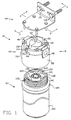
- FIG. 1-6 there are shown two, but not the only, embodiments of the invented filter assemblies 8 and 160, each including a valve head assembly and a cooperating filter cartridge.
- the valve head assembly 10 comprises an outer valve head 12, a piston sleeve 14, a securing ring 16, a piston member 18, an elongated member called a "valve stem” or “stem” 20, a piston return spring 22, seven seals 31, 32, 33, 34, 35, 36, 37, an arm member called a “lever arm” 40, lever arm return spring 42, a mounting bracket 44, and screws or other attachment means.
- the outer valve head 12 is generally cylindrical in shape, with its outer surface being the outer surface of the valve head assembly.
- the outer valve head 12 includes an inlet port 46 and an outlet port 48 near its upper end.
- the inlet and outlet ports 46 and 48 are preferably 180° juxtaposed on the same horizontal plane with the same centerline. These ports 46 and 48 are threaded to receive appropriately-sized pipe fittings (not shown) for connection to a pipe or other fluid conduit.
- the inlet port 46 opens at its lower inside rim into the outer cavity 50.
- the outer cavity 50 is located at the upper central portion of the outer valve head 12 and is of a cylindrical shape that runs along the vertical centerline of the outer valve head 12.
- the lower outside rim 52 of the outer cavity 50 forms a step for engaging a seal 31.
- the outer cavity 50 steps down to an even smaller diameter cylindrical upper cavity 56 above the outer cavity 50.
- the outlet port 48 intersects the upper cavity 56 towards the top end of the cavity 56.
- the outlet port 48 steps up to a larger diameter near the outside of the outer valve head 12, so that the narrow portion of the outlet port 48 near the upper cavity 56 avoids intersecting the outer cavity 50.
- the lower outside portion 58 of the outer valve head 12 provides a securing means for securing and supporting the filter cartridge 60.
- Figure 2 shows the lower outside portion 58 being threaded to cooperate with a threaded filter cartridge 60, but, alternatively, a bayonet cam mechanism or other securing means may be used.
- the top surface 62 of the outer valve head 12 may include four bolt holes or other means to secure the outer valve head 12 to the bracket 44, which is for mounting the filter assembly onto a wall or grating.
- two cavities 64 on the top surface 62 of the outer valve head 12 are formed.
- Two lever slots 66 are 180° juxtaposed to one another and 90° from the inlet and outlet ports 46 and 48 at the outer, upper rim of the outer valve head 12. These lever slots 66 extend vertically from the top of the outer valve head 12 to the horizontal centerline formed by the inlet and outlet ports 46 and 48.
- a lever hole 68 is located at the bottom of each of the cavities 64 directly in line with each lever slot 66 and extends through the outer valve head 12 into the space 71 beside the lower outside portion 58 of the outer valve head 12.
- the piston sleeve 14 is generally cylindrical in shape and is received and secured into the outer cavity 50 of the outer valve head 12.
- a step 70 is formed about half way up the piston sleeve 14 and is used to seat a seal 31 against the step in the lower outside rim 52 of the outer valve head 12.
- Another step 72 is formed at the upper end of the piston sleeve 14 that is used to seat a seal 32 against the upper inside rim 54 of the outer valve head 12.
- a rim 74 protruding from the outer middle part of the piston sleeve 14 is used in securing and sealing the piston sleeve 14 to the outer valve head 12 by means of a securing ring 16.
- the inner surface 75 of the piston sleeve 14 plus the inner surface of the upper cavity 56 forms the valve head assembly inner surface and define a generally-vertical and generally-cylindrical bore 78 for receiving the piston 18 and the upper end or neck 134 of the filter cartridge 60.
- the piston sleeve inner surface 75 and the side surface of the upper cavity 56 are generally vertical and form the upper side surface of the bore 78.
- the upper portion 109 of the upper cavity 56 inner surface is horizontal and forms the top surface of the bore 78.
- openings 76 extend through the piston sleeve wall just above the middle step 70. These openings 76 extend radially inwardly to the cylindrical bore 78 of the piston sleeve 14.
- a seal groove 80 is found at the lower end of this bore 78 on the inner surface 75 for receiving seal 33.
- an inwardly protruding rim 82 is also found at the lower end of this bore 78 on the inner surface 75 for receiving seal 33.
- a ring or securing ring 16 joins the outer valve head 12 and piston sleeve 14 together.
- This securing ring 16 has several drive holes 21 located on its bottom rim. A tooling fixture may be inserted into these drive holes 21 to drive and spin weld the securing ring 16.
- the upper central section of the securing ring 16 forms a rim 17 and a slanted surface 19 extends upward from the rim to form an upwardly-protruding cylinder.
- the slanted surface 19 engages the lower outside rim 52 of the outer valve head 12 and the rim 74 of the piston sleeve 14 and the upwardly protruding cylinder acts as a flash trap during the spin welding process that forms a unified bond between them.
- the preferred closure member is a piston 18, which is an open-ended, hollow, generally cylindrical shape.
- the piston 18 is received coaxially in the cylindrical bore 78 and held from falling out of the piston sleeve 14 by the inwardly protruding rim 82.
- a lower piston seal groove 90 is located in the piston lower portion 92 on the exterior surface 93 of the piston 18, for receiving seal 36.
- the generally cylindrical piston interior surface 95 defines an interior space, which includes a piston upper interior space 102 and a piston lower interior space 104.
- the interior space holds the valve stem 20.
- the piston upper interior space 102 has a larger diameter than the piston lower interior space 104, which results in a ledge 97 at the intersection between the two.
- the piston upper interior space 102 and the ledge 97 hold and support the piston return spring 22.
- the valve stem 20 is generally cylindrical in shape, with a slight curve about three-fourths of the way up the stem 20 to strengthen it.
- the stem 20 has a top cylindrical plate 110 that abuts and is forced against the upper portion 109 of the upper cavity 56 by the return spring 22.
- the stem 20 has an elongated body that extends down through both the upper interior space 102 and the lower interior space 109.
- the stem central body 103 has an elongated exit hole 108 running from above the bottom end 105 of the stem to about three-fourths of the way up the stem 20 so that the upper end 107 of the hole 108 is in fluid communication with the upper cavity 56 and hence with the outlet port 48.
- the elongated hole 108 provides a space between the piston 18 and the stem central body 103, for transmitting fluid from the filter outlet opening 140 up through the piston interior space to enter the upper cavity 56 and then the outlet port 48.
- the elongated exit hole 108 of Fig. 2 - 4 penetrates through the stem 20 from side to side.
- the stem 20 could have one or more elongated channel(s) 113 that penetrate into the central body from the side but do not necessarily go all the way through the stem 20, as in the embodiment of Fig. 5.
- either the elongated hole 108 or alternative elongated channel(s) 113 in the central body 103 are called herein "indentations" and provide a space for fluid flow between the piston interior surface 95 and the stem 20 surface for fluid flow up through the piston interior space.
- the stem 20 also provides an outlet seal 37 for the piston 18 to seat against to block the fluid outlet passage.
- the bottom end 105 of the stem 20 is approximately the same diameter as the piston lower interior space 104 and has a stem seal groove 106 for receiving seal 37.
- valve and filter assembly 8 When valve and filter assembly 8 is in the "off" position, the piston interior surface 95 slides down to seal against seal 37, thus, blocking the space between the piston 18 and the stem 20.
- other shapes of stems besides the stem 20 may be used, as long as the stem member is received in the piston interior space so that fluid may flow up through the hollow piston and the stem member has a bottom end with a seal for cooperation with the piston interior surface 95.
- the piston 18, stem 20, and spring 22 are supported inside the cylindrical bore 78 and touch each other, but they are not attached to each other or to the piston sleeve 14 or outer valve head 12.
- This configuration results in the option of replacing the piston sleeve 14, piston 18, stem 20, and spring 22 by a "passive inner valve head".
- the passive inner valve head (not shown) forms inlet and outlet passages without the action of a valve and, therefore, without the auto shut-off feature when the filter cartridge 60 is removed.
- a valve head assembly with this passive inner head may be useful for applications not needing the auto-shut-off feature in every filter, for example, as part of a bank of filter assemblies where only one shut-off system is needed.
- the lever arm 40 includes a generally cylindrical vertical member 112 and a generally cylindrical horizontal arm 114 connected to and intersecting the vertical member 112 at 90° just below the upper end of the vertical member.
- a finger pad 116 At the outermost end of the horizontal arm 114 is a finger pad 116, which is slightly wider than the vertical member 112 and has grooves on its bottom side for use as a finger grip.
- the upper end 118 of the vertical member 112 is a slightly smaller diameter than the lower end.
- the lever arm return spring 42 is a standard stainless steel spring.
- the mounting bracket 44 has an "L" shaped cross section. Four holes coincide with the holes in the top surface 62 of the outer valve head 12. Four screws are used to attach the mounting bracket 44 to the outer valve head 12. Additional holes or slots 121 and screws, nuts and bolts 120 may be used to mount the bracket to the wall or to the vending machine. An additional hole is located at the front and center of the bracket 44 for receiving the vertical member 112 of the upper end of the lever arm 40.
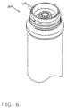
- the filter cartridge 60 comprises a body 122, a cap 124, a central return tube 126, filtering media 128, separator disks 130, and spring disc 150.
- the body 122 is generally cylindrical in shape with an interior space and a large top opening.
- the lower end of the body 122 is covered and may or may not have a small inlet or outlet depending on the filtering process.
- the body 122 has a rim around its top opening for spin welding, or attachment by other means, of the cap 124 to seal the cap 124 to the body 122.
- the cap 124 is a disk shape for covering the top opening of the body 122, and has a cap top surface 131, a cap bottom surface 135, and an outer edge 137.
- the outer rim 132 of the cap extends from the cap top surface 131 and provides a means for securing the filter cartridge 60 to the valve head assembly 10.
- two holes 133 in the top of the rim 132 line up with the lever holes 68 in the outer valve head 12 for receiving the lower end of the lever arm vertical member 112, for acting as a lock means to lock the cartridge 60 into the valve head assembly 10.
- angled cap slots 170 other depressions may be made in the rim for receiving the vertical member 112.
- the lever arm return spring 42 surrounds the upper end 118 of the vertical member 112. It is sandwiched between the mounting bracket 44 and the cylindrical horizontal arm 114. This spring provides a downward force which pushes the lower end 119 of the cylindrical vertical member 112 into a hole 133 or angled cap slots 170 in the top of the filter cap rim 132.
- the lower end 119 may be flat to drop into a hole 133 or it may be terminated at an angle to permit the repeated rise and fall of the lever arm as it moves across the angled cap slots 170. Both of these alternatives prevent an accidental counter-rotation of the filter cartridge without first lifting the finger pad 116 to disengage the hole 133 or angle cap slots 170.
- a cylindrical neck 134 protrudes upward from generally the center of the cap 124.
- a plurality of filter inlet holes 136 extend vertically through the neck 134, downward from the neck top surface 141 to the cap bottom surface 135 to provide the fluid inlet opening into the filtering media 128.
- the inlet holes 136 are located generally around the circumference or perimeter edge 142 of the neck 134 and around a central return hole 138.
- the central return hole 138 also extends vertically down through the neck 134 from the top to the bottom of the cap, and thus, is the filter outlet opening 140.
- On the bottom of the cap 124 are a plurality of ribs 125 for additional strength.
- a cylindrical protrusion 139 extends downward from the bottom of the cap 124 around the central return hole 138. The inside surface of this protrusion 139 angles inward slightly and then angles back out to match the diameter of the central return hole 138 near the top of the neck 134.
- the central return tube 126 collects the filtered fluid at the base of the filter body 122 and delivers it to the central return hole 138.
- Separation disks 130 near the top and near the bottom of the filter cartridge 60 retain the filter media 128 during fluid flow and prevent sediment from passing through the filter. Additional separation disks may be required for additional media.
- the filter cartridge 60 includes a spring disk 150 comprising a bottom perforated plate 152 for resting and pushing down on the media 128 or on a separation disk 130, a top ring 154 for abutting against the ribs 125 of the bottom of the cap 124, and one or more helically-shaped spring members 156 for resiliently connecting the bottom plate 152 to the top ring 154.
- the spring member 156 pushes down the bottom plate 152 and creates a downward force on the media 128. This downward force keeps the media 128 compressed during transport, handling and use, for maintaining good flow distribution through the media.
- filter cartridge refers to any filtering unit, which may be a completely disposable unit, a refillable unit for emptying and refilling with fresh filtering media, or a reusable casing into which a disposable filter may be inserted.
- Filter cartridges may be used that have various flowschemes and various media contained in the cartridge interior space.
- the embodiment shown in the Figures includes a replaceable filter cartridge containing a finely ground granular filtering media in an annular space between the cartridge wall and a central return tube, having an axial flow direction downward through the media, with the central return tube having a fluid inlet at its bottom.
- Another embodiment could include a replaceable filter cartridge containing a radial flow direction porous block filtering media and having a central return tube with fluid inlets along its sides.
- Another embodiment could include a radial flow direction filter containing several layers of porous material filtering media and having a central return tube with fluid inlets along its sides.
- Another embodiment could include a filter containing a reverse osmosis membrane and having a central return tube for the filtered fluid and an outlet at the bottom of the filter for the brine water.
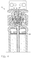
- the "on" position is initiated by the insertion or screwing of the filter cartridge 60 into the valve head assembly 10, so that the neck 134 abuts on the piston lower portion 92 and forces up the piston 18.
- the outer surface of the neck 134 forms a seal with the piston sleeve 14 inner surface 75, by contact with the seal 33.
- the surface of the neck central return hole 138 forms a seal with the lower seal 36 on the piston lower portion 92.
- the fluid may flow from the inlet port 46, into the outer cavity 50, through the openings 76, into the cylindrical bore 78, and into the filter cartridge 60 through the inlet holes 136 in the neck 134.
- the fluid flows through the central return tube 126 into the return hole 138. From the return hole 138, the fluid flows into up through the elongated hole 108 of the stem 20, into the upper cavity 56, and out of the valve head assembly 10 through the outlet port 48.
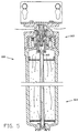
- valve head assembly 10 moves into the "off" position, as shown in Figure 4.
- the piston return spring 22 pushes the piston 18 downward, resulting in the two seals 34, 35 and the vertical exterior surface 93 of the upper portion 94 of the piston covering or flanking the radial openings 76 to stop flow of fluid from the outer cavity 50 into the cylindrical bore 78.
- a seal is formed between the piston lower portion 92 and the bottom end 105 of the stem 20 below the hole 108.
- the seal 37 in stem seal groove 106 contacts the piston interior surface 95 of the piston 18 to prevent any fluid from leaking from the upper cavity 56 or outlet port 48 and flowing out of the piston interior space 101 and down past the stem bottom end 105. Consequently, the filter cartridge 60 may be completely removed from the valve head assembly 10 without leaks or back-flow, from inlet port 46 and outlet port 48, and without having to manually shut off any valves in the fluid conduits. During filter removal, a small amount of fluid, from the cylindrical bore 78 may fall onto the top of the cap 124. The space between the rim 132 and the neck 134 acts like a cup to capture any residual liquid from the disconnection of the filter cartridge 60 from the valve head assembly 10.
- the lever arm 40 When the filter cartridge 60 is fully screwed into the valve head assembly 10, the lever arm 40 is pushed down, so that the vertical member 112 slides down through the lever hole 68 and the lower end of the vertical member 112 enters one of the holes 133 in the top of the cap rim 132. Thus, the filter cartridge 60 is locked from unintentional unscrewing or loosening by vibration.
- the user lifts up on the lever arm 40 to pull the lower end of the vertical member 112 out of the hole 133 or angled slots 170. This then allows the filter cartridge 60 to be rotated counter-clockwise for removal from the valve head assembly 10.
- fluid inlet passage in the valve head assembly 10 may include all or part of the inlet fluid path extending from the valve head outer surface to the filter inlet holes 136, that is, the inlet fluid path that includes the inlet port 46, the outer cavity 50, the openings 76, and part of the piston sleeve cylindrical bore 78.
- fluid outlet passage may include all or part of the outlet fluid path extending from the filter central return hole 138 to the valve head outer surface, that is, the outlet fluid path that includes the piston lower interior space 104, exit hole 108, and piston upper interior space 102 (in other words, the space between the stem and the interior surface of the piston), plus the upper cavity 56 and the outlet port 48.
- references to "inlet” and “outlet” and related directions of fluid flow are made for clear description, but are not meant to limit the invention to specific embodiments or to uses where the fluid flows in a particular direction.
- the invention includes embodiments where fluid is made to flow into the port described herein as the "outlet port” and out of the port described herein as the "inlet port.”
- valve head assembly 10 and filter cartridge 60 may be made of various materials, for example, food-grade plastics or metals suited to a particular application.
- the preferred material for valve head and filter cartridge is plastic.
- the piston return spring 22 is preferably a standard stainless steel spring.
- the seals 31 - 37 may be o-rings or other sealing means, which are not limited to separate, removable sealing members, but include, for example, metal to metal contact or inserts of other sealing materials. Therefore, in the description and claims, references to a surface or a sealing means blocking, closing or sealing a passage, hole, channel, etc., means that the surface or sealing means may do so by various means, including contact by the surface or sealing means or contact by seals or inserts associated with the surface or sealing means.
- This filter assembly 160 comprises valve head assembly 162 and filter cartridge 164.
- the design and operation of filter assembly 160 is substantially the same as filter assembly 8, except for the seal retainer ring 166, eighth seal 168, angled cap slots 170, and the elimination of the outwardly-extending inlet groove 86 of the piston sleeve.
- Seal retainer ring 166 is a generally cylindrical ring which rests in the portion of the central return hole 138 defined by the modified cylindrical protrusion 139'.
- the seal retainer ring 166 holds in place the o-ring 168, which creates a seal between the central return tube 126 and the cylindrical protrusion 139'.
- the angled cap slots 170 of this especially-preferred embodiment are depressions in the rim top surface, which are for receiving the lower end of the lever arm vertical member 112 to serve as a lock means when the filter cartridge 164 is fully installed.
- the lower end of the vertical member 112 may be angled for sliding easily into the angled slots 170.
Landscapes
- Chemical & Material Sciences (AREA)
- Chemical Kinetics & Catalysis (AREA)
- Life Sciences & Earth Sciences (AREA)
- Hydrology & Water Resources (AREA)
- Engineering & Computer Science (AREA)
- Environmental & Geological Engineering (AREA)
- Water Supply & Treatment (AREA)
- Organic Chemistry (AREA)
- Separation Using Semi-Permeable Membranes (AREA)
- Filtering Of Dispersed Particles In Gases (AREA)
- Filtration Of Liquid (AREA)
Description
Claims (11)
- A filter cartridge (60,164) comprising:characterised in thata body (122) with an interior space for receiving filter media (128), the body (122) having an upper end and a lower end;a cap (124) attached to the body (122) near the upper end of the body for enclosing the interior space, the cap (124) having a cap top surface (131), a cap bottom surface (135), and a generally cylindrical neck (134) protruding vertically upward from the cap top surface (131);the neck (134) having a neck top surface (11) with a centre and a perimeter edge (142), and a plurality of generally vertical fluid holes (136) extending through the cap (124) from the neck top surface (141) near said perimeter edge (142);the cap (124) further having a flow hole (138) extending through said centre of the neck (134), the flow hole (138) being generally coaxial with said neck (134);a flow tube (126) received in the body interior space and extending from near the body bottom end to near the body top end, the flow tube (126) being generally coaxial with the flow hole (138) and having a top end received in said flow hole (138);
a generally cylindrical protrusion (139, 139') having a cross-sectional area greater than that of the flow tube extends downward from the neck (134) into the interior space above the media, the protrustion (139, 139') being generally coaxial with said neck (134);
the flow tube (126) has its top end received inside said protrusion (139, 139');
the flow hole (138) extends through and is generally coaxial with said protrusion (139, 139');
said protrustion (139, 139') has a generally cylindrical inner surface surrounding and defining the flow hole (138) through said protrusion (139, 139'); and
said fluid holes are radially outside of the protrusion (139, 139'). - A filter cartridge according to Claim 1 wherein the protrusion has a rim extending radially inward directly above the top end of the flow tube (126) to provide a stop for preventing upward movement of the flow tube (126).
- A filter cartridge according to claim 1 or claim 2 wherein an O-ring (168) is located between, and contacts, the outer surface of the top end of the flow tube (126) and the inner surface of the protrusion (139') to seal the flow tube (126) to the protrusion inner surface; and
a seal retainer ring (166) is received in and generally coaxial with the flow hole (138) in said protrusion (139'), the retainer ring (166) being positioned directly above said O-ring (168) to retain said O-ring (168) between said flow tube (126) and said protrusion inner surface. - A filter cartridge according to any one of Claims 1-3, wherein the cap (124) further comprises a plurality of angled slots (170) in the cap top surface (131), each slot (170) having a generally vertical wall and an angled wall at an acute angle to the vertical wall.
- A filter cartridge according to Claim 4 wherein the body (122) has a central axis and the slots (177) are arranged on an arc about the body central axis.
- An assembly which includes a filter cartridge according to any one of Claims 1-5 and a valve head assembly (10,162), the valve head assembly (10,162) comprising:a valve head (12) comprising a cavity (56,50,78) opening downward, a first port (46), and a second port (48), wherein the cavity (56,50,78) receives the upper end of the cartridge (60,164) and is in fluid communication with the first port (46) and the second port (48);a stem (20) within the cavity (56,50,78), the stem (20) having an indentation (108,113);a closure member (18) within the cavity (56,50,78) having an opening (102,104,109) extending vertically through the closure member (18) and receiving said stem (20), wherein the closure member (18) is movable upward on the stem (20) to a first position wherein the first port (46) and the cartridge (60,164) are in fluid communication by way of the indentation (108,113), and wherein the closure member (18) is movable downward on the stem (20) to a second position wherein fluid communication between the valve head assembly (10,162) and the cartridge (60,164) is blocked;the valve head assembly comprising:a sleeve (14) received and secured in the cavity (56,50,78), the sleeve (14) having an inner surface (75) defining an axial first sleeve opening that receives, and is generally coaxial with, the closure member (18), wherein the sleeve (14) retains the closure member (18) within the cavity (56,50,78), and wherein the sleeve (14) further comprises a radial second sleeve opening (76) for fluid communication between the second port (48) and the cartridge (60,164) when the closure member (18) is in the first position.
- The assembly according to Claim 6, wherein the valve assembly (10,162) further comprises a ring (16) that joins the sleeve (14) to the valve head (12).
- The assembly according to Claim 6 or Claim 7, wherein the valve assembly (10,162) further comprises a spring (22) that biases the closure member (18) away from the first position and toward the second position, and wherein said opening (102,104,109) of the closure member (18) has a first diameter that admits the spring (22) and a second smaller diameter that admits the stem (20).
- The assembly according to any one of Claims 6-8, wherein the sleeve (14) surrounds the closure member (18).
- The assembly according to any one of Claims 6-9, wherein the stem (20) and the valve head (12) are separate, thereby permitting variation in stem alignment with respect to the filter cartridge (60,164).
- The assembly according to any one of Claims 6-10 wherein the sleeve (14) seals to the cartridge (60,164 upper end.
Applications Claiming Priority (3)
| Application Number | Priority Date | Filing Date | Title |
|---|---|---|---|
| US450229 | 1995-05-25 | ||
| US08/450,229 US5591332A (en) | 1995-05-25 | 1995-05-25 | Filter assembly with automatic shut-off and quick-connect filter cartridge |
| PCT/US1996/007701 WO1996037274A1 (en) | 1995-05-25 | 1996-05-24 | Filter assembly with valve head and cartridge |
Publications (2)
| Publication Number | Publication Date |
|---|---|
| EP0837726A1 EP0837726A1 (en) | 1998-04-29 |
| EP0837726B1 true EP0837726B1 (en) | 2002-07-31 |
Family
ID=23787268
Family Applications (1)
| Application Number | Title | Priority Date | Filing Date |
|---|---|---|---|
| EP96916641A Expired - Lifetime EP0837726B1 (en) | 1995-05-25 | 1996-05-24 | Filter assembly with valve head and cartridge |
Country Status (6)
| Country | Link |
|---|---|
| US (2) | US5591332A (en) |
| EP (1) | EP0837726B1 (en) |
| KR (1) | KR100412929B1 (en) |
| AU (1) | AU5932596A (en) |
| DE (1) | DE69622719T2 (en) |
| WO (1) | WO1996037274A1 (en) |
Cited By (1)
| Publication number | Priority date | Publication date | Assignee | Title |
|---|---|---|---|---|
| WO2024237985A1 (en) * | 2023-05-12 | 2024-11-21 | Parker-Hannifin Corporation | Filter assembly having a locking mechanism with enhanced engagement features |
Families Citing this family (155)
| Publication number | Priority date | Publication date | Assignee | Title |
|---|---|---|---|---|
| US5591332A (en) * | 1995-05-25 | 1997-01-07 | Omnipure Filter Co. | Filter assembly with automatic shut-off and quick-connect filter cartridge |
| US20020036162A1 (en) * | 1996-08-08 | 2002-03-28 | Magnusson Jan H. | Appliance with iodinated water source |
| US5753107A (en) * | 1996-08-08 | 1998-05-19 | Wtc Ecomaster Corporation | Dripless purification manifold and cartridge |
| USD455814S1 (en) | 1996-08-08 | 2002-04-16 | Pentapure Incorporated | Cartridge for a water purification and treatment system |
| US5885450A (en) * | 1996-08-14 | 1999-03-23 | Reid; Roger P. | Vessel with captive tube support ring |
| US5865996A (en) * | 1996-08-14 | 1999-02-02 | Reid; Roger P. | Water purifier with collet and tube support |
| US5738335A (en) * | 1996-09-10 | 1998-04-14 | Millipore Corporation | Apparatus for isolating and containing reactive medium |
| US5983938A (en) * | 1997-01-02 | 1999-11-16 | Pure Water, Inc. | Combined faucet and filter assembly |
| US5914037A (en) * | 1997-11-24 | 1999-06-22 | Yen; Chiu-Sen | Filter device for a water filter |
| USD433094S (en) * | 1999-07-16 | 2000-10-31 | Pentapure Incorporated | Cartridge connector |
| WO2001007819A1 (en) * | 1999-07-23 | 2001-02-01 | Filterwerk Mann+Hummel Gmbh | Rapid-action coupling for opening a valve |
| US6354344B1 (en) | 2000-07-18 | 2002-03-12 | Elkay Manufacturing Co. | Automatic shutoff device for filtered bottled water dispenser |
| US20020074292A1 (en) * | 2000-09-26 | 2002-06-20 | Andreas Schlegel | Adsorption vessels |
| BR0114198B1 (en) | 2000-09-26 | 2012-02-22 | filtration units can be traversed by means of removing harmful substances from liquids. | |
| EP1365848A4 (en) * | 2001-03-08 | 2004-10-13 | Oasis Corp | COMBINED FILTER MANIFOLD AND SHUT-OFF VALVE FOR A WATER PURIFICATION SYSTEM |
| GB0110227D0 (en) * | 2001-04-26 | 2001-06-20 | Chloroxy Tech Ltd | Water filter cartridge |
| US20030019819A1 (en) * | 2001-07-30 | 2003-01-30 | Karl Fritze | Hot disconnect replaceable water filter assembly |
| US6632355B2 (en) * | 2001-07-30 | 2003-10-14 | Pentapure Incorporated | Low spillage replaceable water filter assembly |
| AU2003245485A1 (en) * | 2002-06-12 | 2003-12-31 | The Water System Group, Inc. | Purified water supply system |
| US6871835B2 (en) * | 2002-06-20 | 2005-03-29 | Arichell Technologies, Inc. | Flow control valve with automatic shutoff capability |
| JP3819840B2 (en) * | 2002-07-17 | 2006-09-13 | 大日本スクリーン製造株式会社 | Plating apparatus and plating method |
| GB0218318D0 (en) * | 2002-08-07 | 2002-09-11 | Strix Ltd | Water treatment apparatus |
| USD472604S1 (en) | 2002-08-22 | 2003-04-01 | Pentapure Incorporated | Filter manifold connector |
| USD472299S1 (en) | 2002-08-22 | 2003-03-25 | Pentapure Incorporated | Filter cartridge connector |
| US6881334B2 (en) * | 2002-10-31 | 2005-04-19 | Stanadyne Corporation | Eccentric interference retention system for a filter cartridge |
| JP3804949B2 (en) * | 2002-11-12 | 2006-08-02 | トヨタ紡織株式会社 | Fluid filter and drain mechanism thereof, drain jig used in fluid filter, and fluid filter drain method |
| US7052615B2 (en) * | 2002-12-10 | 2006-05-30 | King Technology | Dispensing system |
| WO2004063098A2 (en) * | 2003-01-10 | 2004-07-29 | Tersano Inc. | Pulsed electric field sanitization system and system components |
| RU2371395C2 (en) * | 2003-01-10 | 2009-10-27 | Терсано Инк. | Sanitation system and components, producing ozonised liquid |
| CN101229942A (en) * | 2003-01-10 | 2008-07-30 | 特萨诺公司 | Sanitization system and system components producing ozonated liquid |
| DE602004013731D1 (en) * | 2003-03-05 | 2008-06-26 | Hydranautics | DIPLOCKABLE MEMBRANE MODULE WITH REPLACEABLE MEMBRANE ELEMENTS |
| JP4368890B2 (en) * | 2003-03-10 | 2009-11-18 | スリーエム イノベーティブ プロパティーズ カンパニー | Filter housing assembly |
| USD492753S1 (en) | 2003-04-25 | 2004-07-06 | Procter & Gamble | Fluidic cartridge end piece |
| USD494654S1 (en) | 2003-04-25 | 2004-08-17 | Procter & Gamble Co. | Fluidic cartridge fittings |
| US7000894B2 (en) | 2003-04-25 | 2006-02-21 | Pur Water Purification Products, Inc. | Fluidic cartridges and end pieces thereof |
| US20040251192A1 (en) * | 2003-05-02 | 2004-12-16 | Karl Fritze | Crossflow filtration system with quick dry change elements |
| US7441664B2 (en) * | 2003-05-23 | 2008-10-28 | Pur Water Purification Products Inc. | Water treatment devices and cartridges therefor |
| NL1023520C2 (en) * | 2003-05-23 | 2004-11-24 | Sgt Singapore Holdings Pte Ltd | Quick-change filter system as well as a base and a quick-change filter intended for such a system. |
| US7708958B2 (en) * | 2003-06-26 | 2010-05-04 | Tersano Inc. | System and containers for water filtration and item sanitization |
| US7767168B2 (en) * | 2003-06-26 | 2010-08-03 | Tersano Inc. | Sanitization system and system components |
| WO2004113232A2 (en) * | 2003-06-26 | 2004-12-29 | Tersano Inc. | System and containers for water filtration and item sanitization |
| EP1663442A2 (en) * | 2003-08-27 | 2006-06-07 | 3M Innovative Properties Company | Water filter manifold with integral valve |
| US8215492B2 (en) * | 2003-09-18 | 2012-07-10 | Pur Water Purification Products, Inc. | Water treatment devices and cartridges therefor |
| AU2004276295A1 (en) * | 2003-09-23 | 2005-04-07 | 3M Innovative Properties Company | Reduced pressure water filtration system |
| US7351332B2 (en) * | 2003-10-17 | 2008-04-01 | Varian, Inc. | Chromatography cartridge and method for manufacturing a chromatography cartridge |
| CN1867386A (en) * | 2003-10-17 | 2006-11-22 | 3M创新有限公司 | Water Filtration Manifold Incorporating Valves |
| CN1890520A (en) * | 2003-10-28 | 2007-01-03 | 3M创新有限公司 | Designs for filtration systems within appliances |
| BRPI0506934A (en) * | 2004-01-20 | 2007-06-12 | 3M Innovative Properties Co | integral set, water dispensing tool, and methods for forming a liquid dispenser tool and forming a water dispensing tool |
| RU2006131605A (en) * | 2004-02-03 | 2008-03-10 | Зохар Уотерворкс, Ллс (Us) | FILTER CARTRIDGE AND COLLECTOR ASSEMBLY FOR WATER CLEANING SYSTEM |
| US20050218059A1 (en) * | 2004-03-30 | 2005-10-06 | George Knoll | Fluid filter mounting apparatus and method |
| US6977039B2 (en) * | 2004-03-30 | 2005-12-20 | Natural Choice Corporation | Fluid filter apparatus and method |
| US7077382B2 (en) * | 2004-07-13 | 2006-07-18 | Itt Manufacturing Enterprises, Inc. | Water supply shut off valve with quick connect having flow regulation |
| US7335300B1 (en) * | 2004-07-14 | 2008-02-26 | Wix Filtration Corp Llc | Fluid filter element |
| DE102004049877B4 (en) * | 2004-10-13 | 2008-03-27 | Brita Gmbh | Filter cartridge and seat element for a filter cartridge |
| CN2741960Y (en) | 2004-10-28 | 2005-11-23 | 厦门建霖卫浴工业有限公司 | Water purifier |
| DE602004028501D1 (en) * | 2004-12-22 | 2010-09-16 | Techspace Aero Sa | Multifunctional closure device for lubricant filter |
| CA2771122C (en) * | 2005-01-27 | 2014-05-20 | Ecowater Systems, Llc | Filter cartridge |
| EP1850941B1 (en) * | 2005-02-22 | 2011-04-13 | Baldwin Filters, Inc. | Filter apparatus |
| US8057669B2 (en) | 2005-02-22 | 2011-11-15 | Baldwin Filters, Inc. | Filter element and filter assembly including locking mechanism |
| KR100521117B1 (en) * | 2005-03-11 | 2005-10-12 | 주식회사 마이크로필터 | Water purifier filter having a means of fluid interception |
| KR101276509B1 (en) * | 2005-07-20 | 2013-06-18 | 쓰리엠 이노베이티브 프로퍼티즈 컴파니 | Fluid filtration system |
| US7651070B2 (en) * | 2006-01-19 | 2010-01-26 | Clean & Clear Corporation | Canter element controlled combination manifold, valve and filter module system |
| DE202006019884U1 (en) * | 2006-04-05 | 2008-02-07 | Aquis Wasser-Luft-Systeme Gmbh, Lindau, Zweigniederlassung Rebstein | Water filter cartridge system with combined Verschneidideventiltechnik in the candle and adjusting device in the head |
| US8252173B2 (en) | 2006-04-05 | 2012-08-28 | Aquis Wasser-Luft-Systeme Gmbh, Lindau Zweigniederlassung Rebstein | Water filter cartridge system having a combined blending valve system in the candle and adjusting device in the head |
| DE102007010129B4 (en) | 2006-04-05 | 2022-09-15 | Aquis Wasser-Luft-Systeme Gmbh, Lindau, Zweigniederlassung Rebstein | Water filter cartridge system with combined blending valve technology in the candle and adjustment device in the head |
| US20070251878A1 (en) * | 2006-05-01 | 2007-11-01 | Michael Saveliev | Low volume per output large in-line filter assembly |
| US20070284296A1 (en) | 2006-06-08 | 2007-12-13 | Paragon Water Systems | Filter cartridge and head assembly with internal shutoff valve |
| WO2008017497A1 (en) * | 2006-08-11 | 2008-02-14 | Aquis Wasser-Luft-Systeme Gmbh, Lindau Zweigniederlassung Rebstein | Filter cartridge for water-conducting units |
| DE102007025809B3 (en) * | 2007-06-02 | 2008-10-16 | Dräger Medical AG & Co. KG | Carbon dioxide absorber for a breathing system comprises a guiding plate arranged on the front side of a housing, gas channels arranged on a guiding plate and guiding grooves arranged between the guiding plate and the housing |
| KR100873294B1 (en) * | 2007-06-14 | 2008-12-11 | 웅진코웨이주식회사 | Filter assembly |
| US9211488B2 (en) | 2007-07-13 | 2015-12-15 | Cummins Filtration Ip, Inc. | Fluid filter with localized flow attachment |
| US9308476B2 (en) * | 2007-07-13 | 2016-04-12 | Cummins Filtration Ip, Inc. | Filter with localized flow attachment and filter head |
| CN101376040B (en) * | 2007-08-31 | 2012-06-27 | 深圳迈瑞生物医疗电子股份有限公司 | Installation apparatus of carbon dioxide absorption tank |
| US20100264078A1 (en) * | 2007-10-29 | 2010-10-21 | Bassett Laurence W | Latch reset filter unit |
| US20090166285A1 (en) * | 2008-01-02 | 2009-07-02 | Chuan Chin Shen | Disengagement-preventing device for threading coupling of drinking water filter element |
| US7981197B2 (en) * | 2008-03-07 | 2011-07-19 | Illinois Tool Works Inc. | Easily removable filter bowl for paint spray guns |
| US8007948B2 (en) * | 2008-03-14 | 2011-08-30 | GM Global Technology Operations LLC | Ion exchange cartridge for fuel cell applications |
| US8815090B2 (en) * | 2008-06-16 | 2014-08-26 | Baldwin Filters, Inc. | Filter with water separation device |
| US8241493B2 (en) * | 2008-06-16 | 2012-08-14 | Baldwin Filters, Inc. | Filter with ejection mechanism |
| US8128819B2 (en) * | 2008-06-16 | 2012-03-06 | Baldwin Filters Inc. | Fluid filter, fluid filter assembly, and mounting method |
| USD599880S1 (en) | 2008-06-25 | 2009-09-08 | Envirogard Products Limited | Filter cartridge |
| US20090321340A1 (en) * | 2008-06-25 | 2009-12-31 | Envirogard Products Limited | Filter cartridge for use with a filter head assembly |
| US7744757B1 (en) * | 2008-11-19 | 2010-06-29 | I-Chung Liao | Connection between filtering cap and container |
| CN102438718B (en) | 2009-03-31 | 2015-08-26 | 唐纳森公司 | Liquid filter assemblies, structures, components and methods |
| USD610225S1 (en) | 2009-07-13 | 2010-02-16 | Paragon Water Systems | Key for a water filter assembly |
| US8409337B1 (en) | 2010-06-08 | 2013-04-02 | Aaf-Mcquay Inc. | Air handling filtration equipment with adjustable media bed and method of use |
| CN101979124B (en) * | 2010-09-21 | 2012-07-04 | 浙江沁园水处理科技有限公司 | Anti-looseningning structure of filter core shell |
| DE102010051343B4 (en) * | 2010-11-13 | 2013-01-17 | Daimler Ag | Coolant circuit for a fuel cell system and method for fluidly coupling an ion exchange module with a component of a coolant circuit |
| US8828126B2 (en) * | 2011-02-04 | 2014-09-09 | Leco Corporation | Removable final scrubber tube |
| DE112012001697T5 (en) | 2011-04-12 | 2014-01-16 | Cummins Filtration Ip, Inc. | Filter apparatus with torque limitation |
| USD654564S1 (en) | 2011-09-15 | 2012-02-21 | Whirlpool Corporation | Filter unit |
| US8845896B2 (en) | 2011-09-15 | 2014-09-30 | Whirlpool Corporation | Water filter system |
| US20130068684A1 (en) | 2011-09-15 | 2013-03-21 | Whirlpool Corporation | Filter unit |
| USD654565S1 (en) | 2011-09-15 | 2012-02-21 | Whirlpool Corporation | Filter unit |
| US8950052B2 (en) | 2011-09-15 | 2015-02-10 | Whirlpool Corporation | Method of installing a filter unit |
| US8591736B2 (en) | 2011-09-15 | 2013-11-26 | Whirlpool Corporation | Water filter unit |
| USD654561S1 (en) | 2011-09-15 | 2012-02-21 | Whirlpool Corporation | Filter unit |
| USD654566S1 (en) | 2011-09-15 | 2012-02-21 | Whirlpool Corporation | Filter unit |
| US8413818B1 (en) | 2011-09-15 | 2013-04-09 | Whirlpool Corporation | Filter unit |
| USD654560S1 (en) | 2011-09-15 | 2012-02-21 | Whirlpool Corporation | Filter unit |
| USD655378S1 (en) | 2011-09-15 | 2012-03-06 | Whirlpool Corporation | Filter unit |
| USD655377S1 (en) | 2011-09-15 | 2012-03-06 | Whirlpool Corporation | Filter unit |
| USD654562S1 (en) | 2011-09-15 | 2012-02-21 | Whirlpool Corporation | Filter unit |
| USD654563S1 (en) | 2011-09-15 | 2012-02-21 | Whirlpool Corporation | Filter unit |
| US8580109B2 (en) | 2011-09-15 | 2013-11-12 | Whirlpool Corporation | Electronic interface for water filter system |
| USD654559S1 (en) | 2011-09-15 | 2012-02-21 | Whirlpool Corporation | Filter unit |
| CN103288175A (en) * | 2012-02-22 | 2013-09-11 | 何建明 | Portable waterer |
| US8991619B2 (en) | 2012-03-26 | 2015-03-31 | Baldwin Filters, Inc. | Filter assembly with water evacuation and methods |
| US9447759B2 (en) | 2012-06-12 | 2016-09-20 | Cummins Filtration Ip, Inc. | Filter element endplate defining inflow and outflow flow paths |
| USD712008S1 (en) | 2012-09-25 | 2014-08-26 | Paragon Water Systems, Inc. | Key for a water filter assembly |
| USD690794S1 (en) | 2012-09-25 | 2013-10-01 | Paragon Water Systems, Inc. | Key for a water filter assembly |
| USD690795S1 (en) | 2012-09-25 | 2013-10-01 | Paragon Water Systems, Inc. | Key for a water filter assembly |
| CN103893875B (en) * | 2012-12-27 | 2016-12-28 | 北京谊安医疗系统股份有限公司 | A kind of collateral ventilation device and use the absorption circuit of this device |
| BR112015016047B1 (en) | 2013-01-04 | 2022-05-31 | Baldwin Filters, Inc | End cap for filter element, method of forming it and filter arrangement |
| CN104768625B (en) | 2013-01-21 | 2017-09-15 | 阿普莎娜股份有限公司 | Liquid filtration systems, components and methods |
| US9469551B2 (en) | 2013-05-31 | 2016-10-18 | Kx Technologies Llc | Filter cartridge |
| EP3013446B1 (en) | 2013-06-26 | 2021-12-08 | Pentair Residential Filtration, LLC | Filter cartridge and water filtration system |
| USD718853S1 (en) * | 2013-07-02 | 2014-12-02 | Stealth Innovative Systems, Llc | Air filter and bracket assembly |
| CN103505935B (en) * | 2013-09-30 | 2015-08-19 | 浙江艾波特环保科技股份有限公司 | One connects filter flask fast |
| WO2015164528A1 (en) | 2014-04-23 | 2015-10-29 | Baird Michael T | Water filter cartridge and manifold head seal |
| US9212787B1 (en) * | 2014-06-26 | 2015-12-15 | Aquatic Scientific Co., Ltd. | Leak-detecting shut-off device |
| USD755344S1 (en) | 2014-06-26 | 2016-05-03 | Pentair Residential Filtration, Llc | Filter cartridge |
| US9067154B1 (en) | 2014-11-06 | 2015-06-30 | 3M Innovative Properties Company | Replacement filter cartridge |
| WO2016146152A1 (en) | 2015-03-13 | 2016-09-22 | Volvo Truck Corporation | An engine arrangement |
| DE102015008085A1 (en) * | 2015-06-25 | 2016-12-29 | Mann+Hummel Gmbh | Desulphurisation device for a fuel cell |
| KR101591008B1 (en) | 2015-07-29 | 2016-02-02 | 주식회사 마이크로필터 | Filter Cartridge with Serial Water Path |
| KR101591007B1 (en) | 2015-07-29 | 2016-02-02 | 주식회사 마이크로필터 | Filter Cartridge with Parallel Water Path |
| US20170080365A1 (en) | 2015-09-22 | 2017-03-23 | Caterpillar Inc. | End cap for filter element |
| KR101788965B1 (en) | 2016-03-22 | 2017-10-20 | 엘지전자 주식회사 | water purifing apparatus refrigerator |
| WO2018067437A1 (en) | 2016-10-03 | 2018-04-12 | Parker-Hannifin Corporation | Filter element with torsion lock and assembly |
| GB201701108D0 (en) | 2017-01-23 | 2017-03-08 | Parker Hannifin Mfg (Uk) Ltd | A filter assembly |
| GB201701107D0 (en) | 2017-01-23 | 2017-03-08 | Parker Hannifin Mfg (Uk) Ltd | A filter assembly |
| US10525387B2 (en) | 2017-04-06 | 2020-01-07 | Whirlpool Corporation | Filter cartridge |
| CN110769913B (en) * | 2017-05-31 | 2021-11-16 | 帕克-汉尼芬公司 | Filter element with twist lock and/or sliding piston, assembly and method |
| US10773191B2 (en) | 2017-08-02 | 2020-09-15 | Haier Us Appliance Solutions, Inc. | Filter assembly |
| CN109384282B (en) * | 2017-08-09 | 2022-03-15 | 九阳股份有限公司 | Reverse osmosis filter element subassembly |
| US10584040B2 (en) | 2017-10-06 | 2020-03-10 | Whirlpool Corporation | Filter cartridge |
| US10807025B2 (en) | 2018-08-06 | 2020-10-20 | Whirlpool Corporation | Blind attachment interface for filter housing assembly |
| CN113784773A (en) * | 2019-02-25 | 2021-12-10 | 维沃布鲁股份有限公司 | Water Filtration Method and System |
| US11504657B2 (en) | 2019-03-27 | 2022-11-22 | Haier Us Appliance Solutions, Inc. | Leak detection assembly for use with a filter assembly for a refrigerator appliance |
| US10946319B2 (en) | 2019-03-27 | 2021-03-16 | Haier Us Appliance Solutions, Inc. | Filter assembly for improved filter cartridge placement and detection in a refrigerator appliance |
| CN112843842B (en) * | 2019-11-12 | 2022-05-24 | 杭州科百特过滤器材有限公司 | Filter and mounting and dismounting method thereof |
| CN114980992B (en) | 2020-01-17 | 2026-03-20 | 沃尔沃卡车集团 | Liquid filters equipped with leak-proof valves |
| USD933157S1 (en) * | 2020-03-10 | 2021-10-12 | As America, Inc. | Filter cartridge |
| USD987772S1 (en) | 2020-07-02 | 2023-05-30 | Qingdao Ecopure Filter Co., Ltd. | Water filter |
| PL436258A1 (en) * | 2020-12-07 | 2022-06-13 | Formaster Spółka Akcyjna | Water treatment cartridge for a water treatment device, a water treatment device head and a water treatment device containing such a cartridge and such a head |
| USD1069978S1 (en) | 2021-03-08 | 2025-04-08 | Vivoblu Inc | Filter wingnut |
| AU2022270064A1 (en) * | 2021-05-05 | 2023-12-07 | Renew Health Limited | Sealing assembly and method of use thereof |
| USD987024S1 (en) | 2021-06-09 | 2023-05-23 | Vivoblu Inc | Filter cartridge housing |
| US11872510B2 (en) | 2021-07-01 | 2024-01-16 | Qingdao Ecopure Filter Co., Ltd | Water filter |
| USD1019884S1 (en) | 2021-08-03 | 2024-03-26 | Qingdao Ecopure Filter Co., Ltd. | Water filter |
| USD1016970S1 (en) | 2021-09-03 | 2024-03-05 | Qingdao Ecopure Filter Co., Ltd | Water filter |
| JP7763668B2 (en) * | 2022-01-06 | 2025-11-04 | 株式会社ロキテクノ | Container connection system and fluid container |
| CN114588715B (en) * | 2022-03-11 | 2022-11-25 | 江苏同征新能源汽车零部件有限公司 | Medium filter convenient for replacing filter element for electric automobile heat management system |
| CN115253684A (en) * | 2022-08-01 | 2022-11-01 | 青岛尚禹环保设备科技有限公司 | PTFE milipore filter filtration equipment |
Family Cites Families (32)
| Publication number | Priority date | Publication date | Assignee | Title |
|---|---|---|---|---|
| US2431782A (en) * | 1945-02-07 | 1947-12-02 | Air Maze Corp | Liquid filter valve structure |
| US2544244A (en) * | 1946-07-29 | 1951-03-06 | Vokes Ltd | Filter |
| US2894630A (en) * | 1955-03-29 | 1959-07-14 | Wix Corp | Mounting and adapter for screw neck type filter |
| US2945591A (en) * | 1956-09-20 | 1960-07-19 | Pall Corp | Filter |
| US2932400A (en) * | 1957-04-01 | 1960-04-12 | Purolator Products Inc | Filter unit |
| US3040894A (en) * | 1960-07-12 | 1962-06-26 | Pall Corp | Filter |
| DE1121087B (en) * | 1960-07-15 | 1962-01-04 | Hansa Metallwerke Ag | Refrigerant dryer |
| US3283907A (en) * | 1963-08-08 | 1966-11-08 | Bendix Corp | Filter with automatic shut-off valve |
| US3319791A (en) * | 1964-03-02 | 1967-05-16 | Fred H Horne | Poppet valve and disposable container combination |
| US3317046A (en) * | 1965-01-06 | 1967-05-02 | Bendix Corp | Filter element having plural flapper type bypass valves thereon |
| US3746171A (en) * | 1971-07-21 | 1973-07-17 | J Thomsen | Filter assembly |
| US3715032A (en) * | 1971-11-03 | 1973-02-06 | S Nicko | Fluid treatment devices |
| US4082673A (en) * | 1974-06-10 | 1978-04-04 | Amf Incorporated | Filter asembly with integral service shut-off valve |
| US4077876A (en) * | 1976-01-14 | 1978-03-07 | Amf Incorporated | Shut-off valve apparatus |
| US4222875A (en) * | 1978-04-18 | 1980-09-16 | Deere & Company | Filter element shutoff valve |
| US4199443A (en) * | 1978-05-30 | 1980-04-22 | Tauber Thomas E | Oil monitoring apparatus |
| US4396512A (en) * | 1979-06-01 | 1983-08-02 | Everpure, Inc. | Bacteriostatic filter media |
| DE3114493A1 (en) * | 1981-04-10 | 1982-10-28 | Degussa Ag, 6000 Frankfurt | "FELLING SILICONES AND METHOD FOR THE PRODUCTION THEREOF" |
| US4645601A (en) * | 1984-08-31 | 1987-02-24 | Everpure, Inc. | Quick change reverse osmosis assembly |
| US4654142A (en) * | 1985-11-18 | 1987-03-31 | Everpure, Inc. | Filtering system |
| US4877521A (en) * | 1987-04-30 | 1989-10-31 | Cuno, Incorporated | Quick-change filter cartridge and head therefor |
| US4948505A (en) * | 1986-01-27 | 1990-08-14 | Cuno, Inc. | Quick-change filter cartridge and head therefor |
| US4735716A (en) * | 1986-01-27 | 1988-04-05 | Cuno Corporated | Quick-change filter cartridge and head therefor |
| US4725354A (en) * | 1986-03-07 | 1988-02-16 | Everpure, Inc. | Filtering system |
| US4818397A (en) * | 1986-12-22 | 1989-04-04 | Sundstrand Corporation | Shut-off valve seal |
| US4956086A (en) * | 1988-10-13 | 1990-09-11 | Everpure, Inc. | Filter cartridge with a lugged concentric closure portion |
| US4857189A (en) * | 1988-10-13 | 1989-08-15 | Everpure, Inc. | Filter cartridge with a lugged concentric closure portion |
| US4915831A (en) * | 1989-01-23 | 1990-04-10 | Cuno, Incorporated | Filter assembly featuring displaceable filter head plunger for locking into filter cartridge detent |
| US5092999A (en) * | 1990-02-14 | 1992-03-03 | Ultra Flo, Inc. | Filtering means |
| US5108598A (en) * | 1990-02-14 | 1992-04-28 | Ultra Flow, Inc. | Horizontal motion quick-disconnect filter system with recirculating bypass |
| US5336406A (en) * | 1993-01-26 | 1994-08-09 | Elkay Manufacturing Company | Replaceable filter cartridge and head assembly with safety shut-off valve |
| US5591332A (en) * | 1995-05-25 | 1997-01-07 | Omnipure Filter Co. | Filter assembly with automatic shut-off and quick-connect filter cartridge |
-
1995
- 1995-05-25 US US08/450,229 patent/US5591332A/en not_active Expired - Lifetime
-
1996
- 1996-05-24 KR KR1019970708422A patent/KR100412929B1/en not_active Expired - Fee Related
- 1996-05-24 WO PCT/US1996/007701 patent/WO1996037274A1/en not_active Ceased
- 1996-05-24 DE DE69622719T patent/DE69622719T2/en not_active Expired - Lifetime
- 1996-05-24 AU AU59325/96A patent/AU5932596A/en not_active Abandoned
- 1996-05-24 US US08/656,038 patent/US5744030A/en not_active Expired - Lifetime
- 1996-05-24 EP EP96916641A patent/EP0837726B1/en not_active Expired - Lifetime
Cited By (1)
| Publication number | Priority date | Publication date | Assignee | Title |
|---|---|---|---|---|
| WO2024237985A1 (en) * | 2023-05-12 | 2024-11-21 | Parker-Hannifin Corporation | Filter assembly having a locking mechanism with enhanced engagement features |
Also Published As
| Publication number | Publication date |
|---|---|
| WO1996037274A1 (en) | 1996-11-28 |
| AU5932596A (en) | 1996-12-11 |
| DE69622719T2 (en) | 2003-04-03 |
| US5591332A (en) | 1997-01-07 |
| DE69622719D1 (en) | 2002-09-05 |
| US5744030A (en) | 1998-04-28 |
| KR100412929B1 (en) | 2004-05-31 |
| KR19990021947A (en) | 1999-03-25 |
| EP0837726A1 (en) | 1998-04-29 |
Similar Documents
| Publication | Publication Date | Title |
|---|---|---|
| EP0837726B1 (en) | Filter assembly with valve head and cartridge | |
| US6193884B1 (en) | Dripless purification manifold and cartridge | |
| US5344558A (en) | Water filter cartridge | |
| US5486288A (en) | Mounting head with safety shut-off valve for replaceable filter cartridge | |
| CA2435926C (en) | Fluid filter apparatus | |
| US9687762B2 (en) | Filter cartridge | |
| US5328604A (en) | Filter system having bottom manifold and means for causing filter rotation | |
| US5891334A (en) | Filter cartridge retaining assembly | |
| US6068762A (en) | Reusable oil filter assembly | |
| US6258266B1 (en) | Faucet mount water filtration device | |
| US7264718B2 (en) | Fluid filter apparatus and method | |
| US20050103697A1 (en) | Dripless purification manifold and cartridge | |
| JP3108201U (en) | Spin-on filter element and corresponding filter head | |
| EP0289188B1 (en) | Fluid filter drain assembly | |
| US20020038668A1 (en) | Cartridge adapter | |
| US6926827B2 (en) | Fuel dispenser filter with removable filter media | |
| US6227246B1 (en) | Faucet mixing valve housing with check valves and filter | |
| JPH0729003B2 (en) | Filtration device and its filtration container | |
| JP2004205045A (en) | Fluid filtration system including replaceable filter module | |
| CN117715688A (en) | In-line filter | |
| US6027647A (en) | Multi-element liquid filter system with flushing and filtering circuits | |
| KR200190745Y1 (en) | Filter assembly for rectifier | |
| JP2591130Y2 (en) | Water purifier | |
| CA2304271A1 (en) | Above deck mountable filter cartridge for a filter assembly | |
| JP2590724Y2 (en) | Water purifier |
Legal Events
| Date | Code | Title | Description |
|---|---|---|---|
| PUAI | Public reference made under article 153(3) epc to a published international application that has entered the european phase |
Free format text: ORIGINAL CODE: 0009012 |
|
| 17P | Request for examination filed |
Effective date: 19971223 |
|
| AK | Designated contracting states |
Kind code of ref document: A1 Designated state(s): DE FR GB |
|
| RIN1 | Information on inventor provided before grant (corrected) |
Inventor name: STOCKTON, WARREN, D. Inventor name: CHRISTIANSEN, LANCE, J. Inventor name: REID, ROGER, P. |
|
| 17Q | First examination report despatched |
Effective date: 20000111 |
|
| GRAG | Despatch of communication of intention to grant |
Free format text: ORIGINAL CODE: EPIDOS AGRA |
|
| GRAG | Despatch of communication of intention to grant |
Free format text: ORIGINAL CODE: EPIDOS AGRA |
|
| GRAH | Despatch of communication of intention to grant a patent |
Free format text: ORIGINAL CODE: EPIDOS IGRA |
|
| GRAH | Despatch of communication of intention to grant a patent |
Free format text: ORIGINAL CODE: EPIDOS IGRA |
|
| GRAA | (expected) grant |
Free format text: ORIGINAL CODE: 0009210 |
|
| AK | Designated contracting states |
Kind code of ref document: B1 Designated state(s): DE FR GB |
|
| REG | Reference to a national code |
Ref country code: GB Ref legal event code: FG4D |
|
| REF | Corresponds to: |
Ref document number: 69622719 Country of ref document: DE Date of ref document: 20020905 |
|
| ET | Fr: translation filed | ||
| PLBE | No opposition filed within time limit |
Free format text: ORIGINAL CODE: 0009261 |
|
| STAA | Information on the status of an ep patent application or granted ep patent |
Free format text: STATUS: NO OPPOSITION FILED WITHIN TIME LIMIT |
|
| 26N | No opposition filed |
Effective date: 20030506 |
|
| PGFP | Annual fee paid to national office [announced via postgrant information from national office to epo] |
Ref country code: FR Payment date: 20110603 Year of fee payment: 16 |
|
| PGFP | Annual fee paid to national office [announced via postgrant information from national office to epo] |
Ref country code: GB Payment date: 20110523 Year of fee payment: 16 |
|
| PGFP | Annual fee paid to national office [announced via postgrant information from national office to epo] |
Ref country code: DE Payment date: 20110601 Year of fee payment: 16 |
|
| GBPC | Gb: european patent ceased through non-payment of renewal fee |
Effective date: 20120524 |
|
| REG | Reference to a national code |
Ref country code: FR Ref legal event code: ST Effective date: 20130131 |
|
| REG | Reference to a national code |
Ref country code: DE Ref legal event code: R119 Ref document number: 69622719 Country of ref document: DE Effective date: 20121201 |
|
| PG25 | Lapsed in a contracting state [announced via postgrant information from national office to epo] |
Ref country code: GB Free format text: LAPSE BECAUSE OF NON-PAYMENT OF DUE FEES Effective date: 20120524 Ref country code: FR Free format text: LAPSE BECAUSE OF NON-PAYMENT OF DUE FEES Effective date: 20120531 |
|
| PG25 | Lapsed in a contracting state [announced via postgrant information from national office to epo] |
Ref country code: DE Free format text: LAPSE BECAUSE OF NON-PAYMENT OF DUE FEES Effective date: 20121201 |