EP1886875B1 - Lastenträger für ein Kraftfahrzeug - Google Patents
Lastenträger für ein Kraftfahrzeug Download PDFInfo
- Publication number
- EP1886875B1 EP1886875B1 EP07015559A EP07015559A EP1886875B1 EP 1886875 B1 EP1886875 B1 EP 1886875B1 EP 07015559 A EP07015559 A EP 07015559A EP 07015559 A EP07015559 A EP 07015559A EP 1886875 B1 EP1886875 B1 EP 1886875B1
- Authority
- EP
- European Patent Office
- Prior art keywords
- load carrier
- load
- vehicle
- motor vehicle
- carrying device
- Prior art date
- Legal status (The legal status is an assumption and is not a legal conclusion. Google has not performed a legal analysis and makes no representation as to the accuracy of the status listed.)
- Not-in-force
Links
Images


Classifications
-
- B—PERFORMING OPERATIONS; TRANSPORTING
- B60—VEHICLES IN GENERAL
- B60R—VEHICLES, VEHICLE FITTINGS, OR VEHICLE PARTS, NOT OTHERWISE PROVIDED FOR
- B60R9/00—Supplementary fittings on vehicle exterior for carrying loads, e.g. luggage, sports gear or the like
- B60R9/08—Supplementary fittings on vehicle exterior for carrying loads, e.g. luggage, sports gear or the like specially adapted for sports gear
- B60R9/10—Supplementary fittings on vehicle exterior for carrying loads, e.g. luggage, sports gear or the like specially adapted for sports gear for cycles
-
- B—PERFORMING OPERATIONS; TRANSPORTING
- B60—VEHICLES IN GENERAL
- B60R—VEHICLES, VEHICLE FITTINGS, OR VEHICLE PARTS, NOT OTHERWISE PROVIDED FOR
- B60R9/00—Supplementary fittings on vehicle exterior for carrying loads, e.g. luggage, sports gear or the like
- B60R9/06—Supplementary fittings on vehicle exterior for carrying loads, e.g. luggage, sports gear or the like at vehicle front or rear
Definitions
- the invention relates to a load carrier for a motor vehicle.
- a load carrier for a motor vehicle is known.
- the load carrier for transporting bicycles or other loads is designed in each case according to the principle of a drawer. In a parking position, the load carrier is invisible under the vehicle from the outside. To reach an operating position, the load carrier is pulled back to the rear. The load carrier thus remains permanently on or in the vehicle.
- the DE 20 2005 011 163 U1 discloses a rear carrier which is fastened in the rear region of a vehicle at two attachment points.
- the rear carrier in this case has two rod-shaped adapter, which can be introduced as separate items in each one of the attachment points.
- the rear carrier in this case also has a support frame with two receiving devices with a centering, which centers a respective adapter end piece in the receiving device, so that only pivoting movements are possible between receiving device and adapter.
- a support arrangement for a motor vehicle which has a fork-like configuration with at least two retaining arms, which have a horizontal distance in the mounted state to each other and are interconnected by a cross member arrangement.
- a coupling for a trailer towing device can be fixedly arranged on the cross member arrangement of the carrier arrangement.
- the DE 92 11 316 U1 further describes a Vor-direction for releasably securing a bicycle carrier at the rear of a passenger car whose attachment to the motor vehicle does not require a trailer hitch.
- a first aspect of the invention relates to a load carrier for a motor vehicle.
- the load carrier comprises a mountable to the body mount, relative to a support frame of the load carrier from the rear of the vehicle is pulled out.
- a ball bar is releasably attached.
- the load carrier used works on the principle of a drawer, in which the load carrier is not visible from the outside in a parking position, because he is retracted into the body of the vehicle. In an operating position, a support frame of the load carrier is extended and is ready for receiving loads such as bicycles or other loads. Of the Load carrier is mounted at the rear of the vehicle and is extended for use against the vehicle's longitudinal direction. In this respect, the load carriers can be used, which in the DE 102 52 132 A1 or the DE 10 2004 021 709 A1 are described.
- the load carrier is attached to a bracket attached to the body, for example, on the longitudinal members of the soil structure and the vehicle floor. On the holder a ball bar is attached.
- the embodiment combines a retractable rear load carrier with a trailer hitch.
- it uses the holder twice, in that it not only serves to fasten the ball bar, but also to mount the load carrier. It therefore comes with fewer components than if a load carrier and a towing device were individually mounted on the vehicle.
- the embodiment thus represents an inexpensive solution.
- the support frame of the load carrier has telescoping rails which are guided by the bumper of the associated motor vehicle.
- the load carrier can thus be performed visually appealing drawer-shaped through the bumper, without external attachments that could affect the ride are required.
- the support frame for example, on its telescopic rails, the rear side must be extended or withdrawn.
- the ball bar in the way.
- the ball bar along an obliquely aligned with respect to the vertical axis pivotable is executed. So that the load carrier can be pulled out, the ball bar is previously pivoted obliquely down into a rest position. The ball bar remains permanently on the vehicle, so that no separate stowage of the ball bar when using the load carrier is required for this purpose.
- the ball bar is detachably connected to the holder.
- a coupling mechanism is screwed or welded to the holder, for example, a cross member, and is removed to remove the ball rod whose ball-and-socket latch to remove it.
- the ball bar is removed before removing the support frame.
- the holder is a cross member, for example a U-shaped cross member.
- the cross member often used for a trailer towing device is so far structurally slightly adapted over its U-shape to serve as a fixture for the ball bar.
- the load carrier can then be fastened in a simple manner between the floor structure and the cross member.
- An embodiment further provides that the holder is attached to the side member of the floor structure. This offers the possibility of retracting the telescopic rails to save space in the side members.
- Another aspect of the invention relates to a motor vehicle, such as a car.
- the motor vehicle here has a load carrier, as described above.
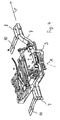
- FIG. 1 shows the rear portion 13 of a motor vehicle 1 with a bumper 2, 2a and a ball rod 3. Behind the hatched area 4, where the license plate is located, is invisible Load carrier 5.
- FIG. 2 shows the vehicle the FIG. 1 in which the load carrier 5 is extended.
- the ball rod 3 is dismantled here.
- the load carrier 5 is drawer-shaped guided by the bumper 2, 2a of the motor vehicle 1, wherein the area 4 for the license plate is also moved backwards and therefore remains visible even when the load carrier is extended.
- FIG. 3 shows the load carrier 5 corresponding to FIG. 1 in the extended to the vehicle rear side position or the operating position.
- the load carrier 5 is about struts 6 and on its underside over in the FIG. 3 invisible screw connected to the body 13, with its U-shaped cross member 7.
- the arrow P indicates the vehicle transverse direction.
- the cross member 7 is in turn connected via lugs 8 with the vehicle floor 9 associated longitudinal members 10.
- the longitudinal member 5 comprises a support frame 11 which can be moved via telescopic rails 12 perpendicular to the direction of arrow P. Since the bumper is 2,2a designed in several parts, results in a retracted into the bumper 2, 2a load carrier 5, apart from additional zero joints an unchanged appearance of the rear portion 14 relative to a motor vehicle 1 without load carrier 5. This design therefore leaves the visual appearance of the vehicle 1 largely untouched.
- FIG. 4 shows the load carrier 5 of FIG. 3 in his parking position.
- the area 4 for the license plate is located approximately above the cross member 7 and the ball bar 3 releasably secured to the cross member 7, namely by screwing.
- the ball rod 3 can be made pivotable about an obliquely oriented to the vertical axis A, so that it is located under the bumper 2, 2a when not in use.
Landscapes
- Engineering & Computer Science (AREA)
- Mechanical Engineering (AREA)
- Fittings On The Vehicle Exterior For Carrying Loads, And Devices For Holding Or Mounting Articles (AREA)
- Seats For Vehicles (AREA)
Description
- Die Erfindung betrifft einen Lastenträger für ein Kraftfahrzeug.
- Sperrige Güter wie beispielsweise Fahrräder, die nicht im Fahrzeuginneren untergebracht werden können, werden in der Regel außen befestigt. Hierfür werden Lastenträger eingesetzt, die entweder auf dem Fahrzeugdach oder am Fahrzeugheck montiert werden. Im Regelfall werden diese Lastenträger nur für den jeweiligen Bedarfsfall am Fahrzeug montiert und bei Nichtbenutzung anderweitig gelagert.
- Aus der
DE 102 52 132 A1 und auch derDE 10 2004 021 709 A1 ist jeweils ein Lastenträger für ein Kraftfahrzeug bekannt. Der Lastenträger zum Transport von Fahrrädern oder anderen Lasten ist dabei jeweils nach dem Prinzip einer Schublade konzipiert. In einer Parkposition befindet sich der Lastenträger von außen unsichtbar unter dem Fahrzeug. Zum Erreichen einer Betriebsstellung wird der Lastenträger heckseitig nach hinten ausgezogen. Der Lastenträger verbleibt damit dauerhaft am bzw. im Fahrzeug. - Aus der
US 6,176,406 B1 ist eine Tragvorrichtung für einen heckseitigen Anbau an Kraftfahrzeugen bekannt, wobei zwei Schubschienen, welche an Fahrgestellteilen verschiebbar gelagert sind, mit einem Transportgestell eine Tragvorrichtung komplettieren. An den Fahrgestellteilen kann ein Querträger mit einer Deichselkupplung angeordnet sein, wobei der Querträger eine zusätzliche Stabilisierung der Tragvorrichtung bereitstellt. - Die
DE 20 2005 011 163 U1 offenbart einen Heckträger, welcher im Heckbereich eines Fahrzeugs an zwei Befestigungspunkten befestigbar ist. Der Heckträger weist hierbei zwei stabförmig ausgebildete Adapter auf, welche als separate Einzelteile in je einen der Befestigungspunkte einbringbar sind. Der Heckträger weist hierbei ferner einen Tragrahmen mit zwei Aufnahmevorrichtungen mit einem Zentrierelement auf, welches ein jeweiliges Adapter-Endstück in der Aufnahmevorrichtung zentriert, so dass zwischen Aufnahmevorrichtung und Adapter nur noch Schwenkbewegungen möglich sind. - Aus der
EP 1 757 488 A2 ist des Weiteren eine Trägeranordnung für ein Kraftfahrzeug bekannt, welche eine gabelartige Gestaltung mit mindestens zwei Haltearmen aufweist, die einen im montierten Zustand horizontalen Abstand zueinander haben und durch eine Querträgeranordnung miteinander verbunden sind. An der Querträgeranordnung der Trägeranordnung kann hierbei eine Kupplung für eine Anhängerzugvorrichtung fest angeordnet sein. - Die
DE 92 11 316 U1 beschreibt ferner eine Vor-richtung zum lösbaren Befestigen eines Fahrradträgers am Heck eines Personenkraftwagens, deren Befestigung am Kraftfahrzeug ohne Anhängerkupplung auskommt. - Schließlich offenbart die
US 2003/0006581 A1 eine schwenkbare Befestigung einer Anhängerkupplung an einem Kraftfahrzeug. - Es ist eine Aufgabe einer Ausführungsform der Erfindung, einen Lastenträger der eingangs genannten Art auf einfache Weise funktionell zu erweitern.
- Die Lösung dieser Aufgabe erfolgt mit den Merkmalen der unabhängigen Ansprüche. Vorteilhafte Weiterbildungen werden durch die Merkmale der abhängigen Ansprüche wiedergegeben.
- Ein erster Aspekt der Erfindung bezieht sich auf einen Lastenträger für ein Kraftfahrzeug. Bei einer ersten Ausführungsform umfasst der Lastenträger eine an der Karosserie befestigbare Halterung, relativ zu der ein Tragrahmen des Lastenträgers aus dem Fahrzeugheck ausziehbar ist. An der Halterung ist eine Kugelstange lösbar befestigt.
- Der eingesetzte Lastenträger funktioniert nach dem Prinzip einer Schublade, bei der in einer Parkposition der Lastenträger von außen nicht sichtbar ist, weil er in die Karosserie des Fahrzeugs eingefahren ist. In einer Betriebsstellung ist ein Tragrahmen des Lastenträgers ausgefahren und steht zur Aufnahme von Lasten wie beispielsweise Fahrrädern oder anderen Lasten bereit. Der Lastenträger ist am Fahrzeugheck montiert und wird für den Einsatz entgegen der Fahrzeuglängsrichtung ausgefahren. Es können insofern die Lastenträger eingesetzt werden, die in der
DE 102 52 132 A1 oder derDE 10 2004 021 709 A1 beschrieben sind. - Der Lastenträger wird mit einer Halterung an der Karosserie befestigt, beispielsweise an den Längsträgern der Bodenstruktur bzw. des Fahrzeugbodens. An der Halterung ist eine Kugelstange befestigt.
- Die Ausführungsform kombiniert einen ausziehbaren Hecklastenträger mit einer Anhängerzugvorrichtung. Sie nutzt hierbei die Halterung doppelt, indem diese nicht nur der Befestigung der Kugelstange dient, sondern auch der Montage des Lastenträgers. Sie kommt daher mit weniger Bauteilen aus, als wenn ein Lastenträger und eine Anhängerzugvorrichtung einzeln am Fahrzeug montiert würden. Die Ausführungsform stellt damit eine preiswerte Lösung dar.
- In einer Ausführungsform besitzt der Tragrahmen des Lastenträgers teleskopierbare Schienen, die durch den Stoßfänger des zugehörigen Kraftfahrzeugs geführt sind. Der Lastenträger kann damit optisch ansprechend schubladenförmig durch den Stoßfänger geführt werden, ohne dass äußere Anbauten, die das Fahrverhalten beeinträchtigen könnten, erforderlich sind.
- Um in die Betriebsstellung des Lastenträgers zu gelangen, muss dessen Tragrahmen, zum Beispiel über seine teleskopierbaren Schienen, heckseitig ausgefahren oder ausgezogen werden. Hierbei kann, abhängig davon, welche Bodenfreiheit das zugehörige Fahrzeug besitzt, die Kugelstange im Weg sein.
- Demgemäß wird in einer weiteren Ausführungsform vorgeschlagen, dass die Kugelstange entlang einer schräg gegenüber der Vertikalen ausgerichteten Achse schwenkbar ausgeführt ist. Damit der Lastenträger ausgezogen werden kann, wird zuvor die Kugelstange schräg nach unten in eine Ruhestellung verschwenkt. Die Kugelstange verbleibt dabei dauerhaft am Fahrzeug, sodass hierfür kein separates Verstauen der Kugelstange bei Benutzung des Lastenträgers erforderlich ist.
- In einer weiteren Ausführungsform wird, als Alternative zur Ausführungsform des vorherigen Absatzes, vorgeschlagen, dass die Kugelstange lösbar mit der Halterung verbunden ist. In diesem Fall ist an die Halterung, beispielsweise einem Querträger, eine Kupplungsmechanik angeschraubt oder angeschweißt, und wird zum Abnehmen der Kugelstange deren Kugelstangen-verriegelung gelöst, um sie abzunehmen. Bei dieser mechanisch einfacheren Lösung wird die Kugelstange vor dem Ausziehen des Tragrahmens demontiert.
- Bei einer Ausführungsform ist die Halterung ein Querträger, beispielsweise ein U-förmiger Querträger. Im letztgenannten Fall ist der für eine Anhängerzugvorrichtung oftmals eingesetzte Querträger insofern über seine U-Form geringfügig baulich angepasst, um als Befestigung für die Kugelstange zu dienen. Zwischen der Bodenstruktur und dem Querträger kann dann der Lastenträger auf einfache Weise befestigt werden.
- Eine Ausführungsform sieht ferner vor, dass die Halterung am Längsträger der Bodenstruktur befestigt ist. Dies bietet die Möglichkeit, die teleskopierbaren Schienen Platz sparend in die Längsträger einfahren zu lassen.
- Ein weiterer Aspekt der Erfindung bezieht sich auf ein Kraftfahrzeug, beispielsweise einem Pkw. Das Kraftfahrzeug besitzt hierbei einen Lastenträger, wie oben beschrieben.
- Weitere Merkmale und Vorteile der beanspruchten Erfindung werden aus der folgenden detaillierten Beschreibung mit Bezug auf die beigefügten Zeichnungen erkennbar die nachfolgend als nicht beschränkende Beispiele angegeben sind. Hierbei soll die Benutzung von Bezugszeichen in den Figuren nicht dahingehend verstanden werden, dass die Bezugszeichen den Schutzumfang der beanspruchten Erfindung einschränken sollen. Es zeigen:
- Figur 1
- ein Kraftfahrzeug mit einem eingefahrenen Lastenträger,
- Figur 2
- ein Kraftfahrzeug mit einem ausgefahrenen Lastenträger,
- Figur 3
- den Lastenträger in seiner Betriebsstellung,
- Figur 4
- den Lastenträger in seiner Ruheposition.
-
Figur 1 zeigt den Heckbereich 13 eines Kraftfahrzeugs 1 mit einem Stoßfänger 2, 2a und einer Kugelstange 3. Hinter dem schraffierten Bereich 4, wo das Nummernschild angeordnet wird, befindet sich unsichtbar ein Lastenträger 5. -
Figur 2 zeigt das Fahrzeug derFigur 1 , bei dem der Lastenträger 5 ausgefahren ist. Die Kugelstange 3 ist hierbei demontiert. Der Lastenträger 5 ist schubladenförmig durch den Stoßfänger 2, 2a des Kraftfahrzeugs 1 geführt, wobei der Bereich 4 für das Nummernschild ebenfalls mit nach hinten verschoben ist und daher auch bei ausgezogenem Lastenträger sichtbar bleibt. -
Figur 3 zeigt den Lastenträger 5 korrespondierend zuFigur 1 in der zur Fahrzeugrückseite hin ausgefahrenen Position bzw. der Betriebsstellung. Der Lastenträger 5 ist über Streben 6 sowie auf seiner Unterseite über in derFigur 3 nicht sichtbare Schraubverbindungen mit der Karosserie 13 verbunden, und zwar mit deren U-förmigem Querträger 7. Der Pfeil P gibt hierzu die Fahrzeugquerrichtung an. Der Querträger 7 ist seinerseits über Ansatzstücke 8 mit den zum Fahrzeugboden 9 gehörenden Längsträgern 10 verbunden. - Der Längsträger 5 umfasst einen Tragrahmen 11, der über teleskopierbare Schienen 12 senkrecht zur Pfeilrichtung P verschoben werden kann. Da der Stoßfänger 2,2a mehrteilig ausgestaltet ist, ergibt sich bei einem in den Stoßfänger 2, 2a eingefahrenen Lastenträger 5 abgesehen von zusätzlichen Nullfugen ein unverändertes Erscheinungsbild des Heckbereichs 14 gegenüber einem Kraftfahrzeug 1 ohne Lastenträger 5. Diese Gestaltung lässt daher das optische Erscheinungsbild des Fahrzeugs 1 weitestgehend unberührt.
-
Figur 4 zeigt den Lastenträger 5 derFigur 3 in seiner Parkposition. In der Parkposition befindet sich der Bereich 4 für das Nummernschild in etwa über dem Querträger 7 und kann die Kugelstange 3 lösbar am Querträger 7 befestigt, nämlich durch Verschraubung. Alternativ kann die Kugelstange 3 über eine schräg zur Vertikalen ausgerichtete Achse A schwenkbar ausgeführt sein, sodass sie bei Nichtbenutzung unter dem Stoßfänger 2, 2a angeordnet ist. -
- 01
- Kraftfahrzeug
- 02
- Stoßfänger
- 02a
- Stoßfänger
- 03
- Kugelstange
- 04
- Bereich
- 05
- Lastenträger
- 06
- Strebe
- 07
- Querträger
- 08
- Ansatzstück
- 09
- Fahrzeugboden
- 10
- Längsträger
- 11
- Tragrahmen
- 12
- Schiene
- 13
- Karosserie
- 14
- Heckbereich
- P
- Pfeil
- A
- Achse
Claims (6)
- Lastenträger (5) für ein Kraftfahrzeug (1), umfassend eine an der Karosserie (13) befestigbare Halterung (7), relativ zu der ein Tragrahmen (11) des Lastenträgers aus dem Fahrzeugheck (14) ausziehbar ist, sowie eine an der Halterung (7) befestigte Kugelstange (3) einer Anhängerzugvorrichtung, dadurch gekennzeichnet, dass die Kugelstange (3) lösbar mit der Halterung (7) verbunden ist.
- Lastenträger nach Anspruch 1, bei dem der Tragrahmen an teleskopierbaren Schienen (12) durch den Stoßfänger (2,2a) eines Kraftfahrzeugs durchführbar ist.
- Lastenträger nach einem der vorherigen Ansprüche, bei dem die Kugelstange entlang einer schräg gegenüber der Vertikalen ausgerichteten Achse schwenkbar ist.
- Lastenträger nach einem der vorherigen Ansprüche, bei dem die Halterung ein Querträger (7) ist.
- Lastenträger nach einem der vorherigen Ansprüche, bei dem die Halterung am Längsträger (10) des Fahrzeugbodens (9) befestigt ist.
- Kraftfahrzeug (1) mit einem Lastenträger (5) nach einem der vorherigen Ansprüche.
Applications Claiming Priority (1)
| Application Number | Priority Date | Filing Date | Title |
|---|---|---|---|
| DE102006036856A DE102006036856A1 (de) | 2006-08-07 | 2006-08-07 | Lastenträger für ein Kraftfahrzeug |
Publications (3)
| Publication Number | Publication Date |
|---|---|
| EP1886875A2 EP1886875A2 (de) | 2008-02-13 |
| EP1886875A3 EP1886875A3 (de) | 2009-05-20 |
| EP1886875B1 true EP1886875B1 (de) | 2011-10-19 |
Family
ID=38649966
Family Applications (1)
| Application Number | Title | Priority Date | Filing Date |
|---|---|---|---|
| EP07015559A Not-in-force EP1886875B1 (de) | 2006-08-07 | 2007-08-07 | Lastenträger für ein Kraftfahrzeug |
Country Status (3)
| Country | Link |
|---|---|
| EP (1) | EP1886875B1 (de) |
| AT (1) | ATE529296T1 (de) |
| DE (1) | DE102006036856A1 (de) |
Families Citing this family (2)
| Publication number | Priority date | Publication date | Assignee | Title |
|---|---|---|---|---|
| US9533625B2 (en) | 2014-10-16 | 2017-01-03 | Ford Global Technologies, Llc | Bike rack attachment for vehicle |
| DE102016219028B4 (de) | 2016-09-30 | 2024-05-23 | Ford Motor Company | Mobilitätseinheit |
Family Cites Families (8)
| Publication number | Priority date | Publication date | Assignee | Title |
|---|---|---|---|---|
| DE9211316U1 (de) * | 1992-08-22 | 1992-11-12 | Braasch, Hans, 4133 Neukirchen-Vluyn, De | |
| DE29600485U1 (de) * | 1996-01-12 | 1997-05-15 | Smv Metall Gmbh | Tragvorrichtung für einen heckseitigen Anbau an Kraftfahrzeugen |
| DE19612959A1 (de) * | 1996-04-01 | 1997-10-02 | Oris Fahrzeugteile Riehle H | Anhängekupplung |
| US6789815B2 (en) * | 2000-04-27 | 2004-09-14 | Wing Enterprises, Inc. | Stowable-lock, convertible-pintle hitch |
| DE10338723B8 (de) * | 2003-08-22 | 2018-07-12 | GM Global Technology Operations LLC (n. d. Ges. d. Staates Delaware) | Vorrichtung zum Transport von Gegenständen an einem Fahrzeugheck |
| DE102004021709B4 (de) * | 2004-04-30 | 2006-10-26 | Cts Fahrzeug-Dachsysteme Gmbh | Ausziehbarer Fahrrad-Heckträger für Fahrzeuge, insbesondere Personenkraftwagen |
| DE202005011163U1 (de) * | 2004-10-08 | 2005-09-22 | Uebler, Klaus | Heckträger, insbesondere für Fahrräder |
| ATE523384T1 (de) * | 2005-08-25 | 2011-09-15 | Westfalia Automotive Gmbh | Trägeranordnung für ein kraftfahrzeug |
-
2006
- 2006-08-07 DE DE102006036856A patent/DE102006036856A1/de not_active Withdrawn
-
2007
- 2007-08-07 AT AT07015559T patent/ATE529296T1/de active
- 2007-08-07 EP EP07015559A patent/EP1886875B1/de not_active Not-in-force
Also Published As
| Publication number | Publication date |
|---|---|
| EP1886875A2 (de) | 2008-02-13 |
| EP1886875A3 (de) | 2009-05-20 |
| DE102006036856A1 (de) | 2008-02-21 |
| ATE529296T1 (de) | 2011-11-15 |
Similar Documents
| Publication | Publication Date | Title |
|---|---|---|
| EP2134571B1 (de) | Lastenträger für ein kraftfahrzeug | |
| DE102004021709A1 (de) | Ausziehbarer Fahrrad-Heckträger für Fahrzeuge, insbesondere Personenkraftwagen | |
| EP1972501B1 (de) | Lastenträger für ein Kraftfahrzeug | |
| DE102005036590B4 (de) | Wohnmobil | |
| DE202009011491U1 (de) | Fahrgestell | |
| EP1886875B1 (de) | Lastenträger für ein Kraftfahrzeug | |
| DE19856848C2 (de) | Kupplungsgebundener Fahrzeugheckträger | |
| DE10252132A1 (de) | Lastenträger für Kraftfahrzeuge zum Ausziehen aus dem Fahrzeugheck | |
| EP0289832A1 (de) | Schutzeinrichtung für den Innenraum von Kraftfahrzeugen | |
| DE19938991B4 (de) | Heckträger für ein Kraftfahrzeug | |
| DE202023100599U1 (de) | Innenlader mit variablem Unterfahrschutz | |
| DE102006042771B4 (de) | Fahrzeugrahmen und Verfahren zur Herstellung eines derartigen Fahrzeugrahmens | |
| DE102015001804A1 (de) | Lastenträger zur Anordnung am Heck eines Kraftfahrzeugs | |
| DE4416456C1 (de) | Vorrichtung zur schutzweisen Abtrennung des Raumes hinter dem Vorder- oder Hintersitz eines Personenkraftfahrzeugs | |
| EP2543549B1 (de) | Lastenträgervorrichtung, vorzugsweise für einen Personenkraftwagen | |
| DE102004064293A1 (de) | Klappbare Unterfahrschutzeinrichtung | |
| DE102011121400A1 (de) | Gepäckhalter für Fahrzeuge sowie Kraftfahrzeug | |
| DE202019101978U1 (de) | Trageinrichtung | |
| EP2368766B1 (de) | Transportbox | |
| DE2339637A1 (de) | Anhaengevorrichtung | |
| AT524815B1 (de) | integrierter Fahrradträger | |
| DE10260470A1 (de) | Outdoor Ladehilfe am Fahrzeugheck eines Kraftfahrzeuges | |
| DE102010010199B4 (de) | Mehrachsiges Kraftfahrzeug mit heckseitiger Ladeflächenvergrößerung | |
| DE102009032594A1 (de) | Lastenträgereinrichtung für ein Kraftfahrzeug | |
| DE10009962B4 (de) | Trägersystem für ein Fahrzeugheck, insbesondere für Fahrräder |
Legal Events
| Date | Code | Title | Description |
|---|---|---|---|
| PUAI | Public reference made under article 153(3) epc to a published international application that has entered the european phase |
Free format text: ORIGINAL CODE: 0009012 |
|
| AK | Designated contracting states |
Kind code of ref document: A2 Designated state(s): AT BE BG CH CY CZ DE DK EE ES FI FR GB GR HU IE IS IT LI LT LU LV MC MT NL PL PT RO SE SI SK TR |
|
| AX | Request for extension of the european patent |
Extension state: AL BA HR MK YU |
|
| PUAL | Search report despatched |
Free format text: ORIGINAL CODE: 0009013 |
|
| AK | Designated contracting states |
Kind code of ref document: A3 Designated state(s): AT BE BG CH CY CZ DE DK EE ES FI FR GB GR HU IE IS IT LI LT LU LV MC MT NL PL PT RO SE SI SK TR |
|
| AX | Request for extension of the european patent |
Extension state: AL BA HR MK RS |
|
| RIC1 | Information provided on ipc code assigned before grant |
Ipc: B60R 9/10 20060101AFI20071113BHEP Ipc: B60D 1/06 20060101ALI20090416BHEP |
|
| 17P | Request for examination filed |
Effective date: 20091120 |
|
| AKX | Designation fees paid |
Designated state(s): AT BE BG CH CY CZ DE DK EE ES FI FR GB GR HU IE IS IT LI LT LU LV MC MT NL PL PT RO SE SI SK TR |
|
| 17Q | First examination report despatched |
Effective date: 20100108 |
|
| GRAP | Despatch of communication of intention to grant a patent |
Free format text: ORIGINAL CODE: EPIDOSNIGR1 |
|
| RAP1 | Party data changed (applicant data changed or rights of an application transferred) |
Owner name: GM GLOBAL TECHNOLOGY OPERATIONS LLC |
|
| GRAS | Grant fee paid |
Free format text: ORIGINAL CODE: EPIDOSNIGR3 |
|
| GRAA | (expected) grant |
Free format text: ORIGINAL CODE: 0009210 |
|
| AK | Designated contracting states |
Kind code of ref document: B1 Designated state(s): AT BE BG CH CY CZ DE DK EE ES FI FR GB GR HU IE IS IT LI LT LU LV MC MT NL PL PT RO SE SI SK TR |
|
| REG | Reference to a national code |
Ref country code: GB Ref legal event code: FG4D Free format text: NOT ENGLISH |
|
| REG | Reference to a national code |
Ref country code: CH Ref legal event code: EP |
|
| REG | Reference to a national code |
Ref country code: IE Ref legal event code: FG4D |
|
| REG | Reference to a national code |
Ref country code: DE Ref legal event code: R096 Ref document number: 502007008404 Country of ref document: DE Effective date: 20111215 |
|
| REG | Reference to a national code |
Ref country code: NL Ref legal event code: VDEP Effective date: 20111019 |
|
| LTIE | Lt: invalidation of european patent or patent extension |
Effective date: 20111019 |
|
| PG25 | Lapsed in a contracting state [announced via postgrant information from national office to epo] |
Ref country code: LT Free format text: LAPSE BECAUSE OF FAILURE TO SUBMIT A TRANSLATION OF THE DESCRIPTION OR TO PAY THE FEE WITHIN THE PRESCRIBED TIME-LIMIT Effective date: 20111019 Ref country code: IS Free format text: LAPSE BECAUSE OF FAILURE TO SUBMIT A TRANSLATION OF THE DESCRIPTION OR TO PAY THE FEE WITHIN THE PRESCRIBED TIME-LIMIT Effective date: 20120219 |
|
| REG | Reference to a national code |
Ref country code: IE Ref legal event code: FD4D |
|
| PG25 | Lapsed in a contracting state [announced via postgrant information from national office to epo] |
Ref country code: SI Free format text: LAPSE BECAUSE OF FAILURE TO SUBMIT A TRANSLATION OF THE DESCRIPTION OR TO PAY THE FEE WITHIN THE PRESCRIBED TIME-LIMIT Effective date: 20111019 Ref country code: GR Free format text: LAPSE BECAUSE OF FAILURE TO SUBMIT A TRANSLATION OF THE DESCRIPTION OR TO PAY THE FEE WITHIN THE PRESCRIBED TIME-LIMIT Effective date: 20120120 Ref country code: NL Free format text: LAPSE BECAUSE OF FAILURE TO SUBMIT A TRANSLATION OF THE DESCRIPTION OR TO PAY THE FEE WITHIN THE PRESCRIBED TIME-LIMIT Effective date: 20111019 Ref country code: PT Free format text: LAPSE BECAUSE OF FAILURE TO SUBMIT A TRANSLATION OF THE DESCRIPTION OR TO PAY THE FEE WITHIN THE PRESCRIBED TIME-LIMIT Effective date: 20120220 Ref country code: SE Free format text: LAPSE BECAUSE OF FAILURE TO SUBMIT A TRANSLATION OF THE DESCRIPTION OR TO PAY THE FEE WITHIN THE PRESCRIBED TIME-LIMIT Effective date: 20111019 Ref country code: LV Free format text: LAPSE BECAUSE OF FAILURE TO SUBMIT A TRANSLATION OF THE DESCRIPTION OR TO PAY THE FEE WITHIN THE PRESCRIBED TIME-LIMIT Effective date: 20111019 |
|
| PG25 | Lapsed in a contracting state [announced via postgrant information from national office to epo] |
Ref country code: CY Free format text: LAPSE BECAUSE OF FAILURE TO SUBMIT A TRANSLATION OF THE DESCRIPTION OR TO PAY THE FEE WITHIN THE PRESCRIBED TIME-LIMIT Effective date: 20111019 |
|
| PG25 | Lapsed in a contracting state [announced via postgrant information from national office to epo] |
Ref country code: DK Free format text: LAPSE BECAUSE OF FAILURE TO SUBMIT A TRANSLATION OF THE DESCRIPTION OR TO PAY THE FEE WITHIN THE PRESCRIBED TIME-LIMIT Effective date: 20111019 Ref country code: BG Free format text: LAPSE BECAUSE OF FAILURE TO SUBMIT A TRANSLATION OF THE DESCRIPTION OR TO PAY THE FEE WITHIN THE PRESCRIBED TIME-LIMIT Effective date: 20120119 Ref country code: CZ Free format text: LAPSE BECAUSE OF FAILURE TO SUBMIT A TRANSLATION OF THE DESCRIPTION OR TO PAY THE FEE WITHIN THE PRESCRIBED TIME-LIMIT Effective date: 20111019 Ref country code: EE Free format text: LAPSE BECAUSE OF FAILURE TO SUBMIT A TRANSLATION OF THE DESCRIPTION OR TO PAY THE FEE WITHIN THE PRESCRIBED TIME-LIMIT Effective date: 20111019 Ref country code: IE Free format text: LAPSE BECAUSE OF FAILURE TO SUBMIT A TRANSLATION OF THE DESCRIPTION OR TO PAY THE FEE WITHIN THE PRESCRIBED TIME-LIMIT Effective date: 20111019 Ref country code: SK Free format text: LAPSE BECAUSE OF FAILURE TO SUBMIT A TRANSLATION OF THE DESCRIPTION OR TO PAY THE FEE WITHIN THE PRESCRIBED TIME-LIMIT Effective date: 20111019 |
|
| PLBE | No opposition filed within time limit |
Free format text: ORIGINAL CODE: 0009261 |
|
| STAA | Information on the status of an ep patent application or granted ep patent |
Free format text: STATUS: NO OPPOSITION FILED WITHIN TIME LIMIT |
|
| PG25 | Lapsed in a contracting state [announced via postgrant information from national office to epo] |
Ref country code: PL Free format text: LAPSE BECAUSE OF FAILURE TO SUBMIT A TRANSLATION OF THE DESCRIPTION OR TO PAY THE FEE WITHIN THE PRESCRIBED TIME-LIMIT Effective date: 20111019 Ref country code: IT Free format text: LAPSE BECAUSE OF FAILURE TO SUBMIT A TRANSLATION OF THE DESCRIPTION OR TO PAY THE FEE WITHIN THE PRESCRIBED TIME-LIMIT Effective date: 20111019 Ref country code: RO Free format text: LAPSE BECAUSE OF FAILURE TO SUBMIT A TRANSLATION OF THE DESCRIPTION OR TO PAY THE FEE WITHIN THE PRESCRIBED TIME-LIMIT Effective date: 20111019 |
|
| 26N | No opposition filed |
Effective date: 20120720 |
|
| REG | Reference to a national code |
Ref country code: DE Ref legal event code: R097 Ref document number: 502007008404 Country of ref document: DE Effective date: 20120720 |
|
| BERE | Be: lapsed |
Owner name: GM GLOBAL TECHNOLOGY OPERATIONS LLC Effective date: 20120831 |
|
| REG | Reference to a national code |
Ref country code: CH Ref legal event code: PL |
|
| PG25 | Lapsed in a contracting state [announced via postgrant information from national office to epo] |
Ref country code: MC Free format text: LAPSE BECAUSE OF NON-PAYMENT OF DUE FEES Effective date: 20120831 |
|
| PG25 | Lapsed in a contracting state [announced via postgrant information from national office to epo] |
Ref country code: CH Free format text: LAPSE BECAUSE OF NON-PAYMENT OF DUE FEES Effective date: 20120831 Ref country code: ES Free format text: LAPSE BECAUSE OF FAILURE TO SUBMIT A TRANSLATION OF THE DESCRIPTION OR TO PAY THE FEE WITHIN THE PRESCRIBED TIME-LIMIT Effective date: 20120130 Ref country code: LI Free format text: LAPSE BECAUSE OF NON-PAYMENT OF DUE FEES Effective date: 20120831 |
|
| PG25 | Lapsed in a contracting state [announced via postgrant information from national office to epo] |
Ref country code: BE Free format text: LAPSE BECAUSE OF NON-PAYMENT OF DUE FEES Effective date: 20120831 |
|
| PG25 | Lapsed in a contracting state [announced via postgrant information from national office to epo] |
Ref country code: FI Free format text: LAPSE BECAUSE OF FAILURE TO SUBMIT A TRANSLATION OF THE DESCRIPTION OR TO PAY THE FEE WITHIN THE PRESCRIBED TIME-LIMIT Effective date: 20111019 |
|
| REG | Reference to a national code |
Ref country code: AT Ref legal event code: MM01 Ref document number: 529296 Country of ref document: AT Kind code of ref document: T Effective date: 20120831 |
|
| PG25 | Lapsed in a contracting state [announced via postgrant information from national office to epo] |
Ref country code: AT Free format text: LAPSE BECAUSE OF NON-PAYMENT OF DUE FEES Effective date: 20120831 |
|
| PG25 | Lapsed in a contracting state [announced via postgrant information from national office to epo] |
Ref country code: MT Free format text: LAPSE BECAUSE OF FAILURE TO SUBMIT A TRANSLATION OF THE DESCRIPTION OR TO PAY THE FEE WITHIN THE PRESCRIBED TIME-LIMIT Effective date: 20111019 |
|
| PG25 | Lapsed in a contracting state [announced via postgrant information from national office to epo] |
Ref country code: TR Free format text: LAPSE BECAUSE OF FAILURE TO SUBMIT A TRANSLATION OF THE DESCRIPTION OR TO PAY THE FEE WITHIN THE PRESCRIBED TIME-LIMIT Effective date: 20111019 |
|
| PG25 | Lapsed in a contracting state [announced via postgrant information from national office to epo] |
Ref country code: LU Free format text: LAPSE BECAUSE OF NON-PAYMENT OF DUE FEES Effective date: 20120807 |
|
| PG25 | Lapsed in a contracting state [announced via postgrant information from national office to epo] |
Ref country code: HU Free format text: LAPSE BECAUSE OF FAILURE TO SUBMIT A TRANSLATION OF THE DESCRIPTION OR TO PAY THE FEE WITHIN THE PRESCRIBED TIME-LIMIT Effective date: 20070807 |
|
| REG | Reference to a national code |
Ref country code: FR Ref legal event code: PLFP Year of fee payment: 10 |
|
| PGFP | Annual fee paid to national office [announced via postgrant information from national office to epo] |
Ref country code: GB Payment date: 20160803 Year of fee payment: 10 |
|
| PGFP | Annual fee paid to national office [announced via postgrant information from national office to epo] |
Ref country code: FR Payment date: 20160712 Year of fee payment: 10 |
|
| GBPC | Gb: european patent ceased through non-payment of renewal fee |
Effective date: 20170807 |
|
| REG | Reference to a national code |
Ref country code: FR Ref legal event code: ST Effective date: 20180430 |
|
| PG25 | Lapsed in a contracting state [announced via postgrant information from national office to epo] |
Ref country code: GB Free format text: LAPSE BECAUSE OF NON-PAYMENT OF DUE FEES Effective date: 20170807 |
|
| PG25 | Lapsed in a contracting state [announced via postgrant information from national office to epo] |
Ref country code: FR Free format text: LAPSE BECAUSE OF NON-PAYMENT OF DUE FEES Effective date: 20170831 |
|
| PGFP | Annual fee paid to national office [announced via postgrant information from national office to epo] |
Ref country code: DE Payment date: 20180724 Year of fee payment: 12 |
|
| REG | Reference to a national code |
Ref country code: DE Ref legal event code: R119 Ref document number: 502007008404 Country of ref document: DE |
|
| PG25 | Lapsed in a contracting state [announced via postgrant information from national office to epo] |
Ref country code: DE Free format text: LAPSE BECAUSE OF NON-PAYMENT OF DUE FEES Effective date: 20200303 |