EP1884976B1 - Schaltvorrichtung mit Betätigungselement - Google Patents
Schaltvorrichtung mit Betätigungselement Download PDFInfo
- Publication number
- EP1884976B1 EP1884976B1 EP07112882A EP07112882A EP1884976B1 EP 1884976 B1 EP1884976 B1 EP 1884976B1 EP 07112882 A EP07112882 A EP 07112882A EP 07112882 A EP07112882 A EP 07112882A EP 1884976 B1 EP1884976 B1 EP 1884976B1
- Authority
- EP
- European Patent Office
- Prior art keywords
- switching device
- pawl
- contact carrier
- actuating element
- switching
- Prior art date
- Legal status (The legal status is an assumption and is not a legal conclusion. Google has not performed a legal analysis and makes no representation as to the accuracy of the status listed.)
- Active
Links
Images


Classifications
-
- H—ELECTRICITY
- H01—ELECTRIC ELEMENTS
- H01H—ELECTRIC SWITCHES; RELAYS; SELECTORS; EMERGENCY PROTECTIVE DEVICES
- H01H71/00—Details of the protective switches or relays covered by groups H01H73/00 - H01H83/00
- H01H71/10—Operating or release mechanisms
- H01H71/50—Manual reset mechanisms which may be also used for manual release
- H01H71/52—Manual reset mechanisms which may be also used for manual release actuated by lever
- H01H71/528—Manual reset mechanisms which may be also used for manual release actuated by lever comprising a toggle or collapsible link between handle and contact arm, e.g. sear pin mechanism
-
- H—ELECTRICITY
- H01—ELECTRIC ELEMENTS
- H01H—ELECTRIC SWITCHES; RELAYS; SELECTORS; EMERGENCY PROTECTIVE DEVICES
- H01H11/00—Apparatus or processes specially adapted for the manufacture of electric switches
- H01H11/0006—Apparatus or processes specially adapted for the manufacture of electric switches for converting electric switches
- H01H11/0018—Apparatus or processes specially adapted for the manufacture of electric switches for converting electric switches for allowing different operating parts
- H01H2011/0025—Apparatus or processes specially adapted for the manufacture of electric switches for converting electric switches for allowing different operating parts with provisions for allowing different orientation of the operating part, e.g. turning knob can be mounted in different positions
-
- H—ELECTRICITY
- H01—ELECTRIC ELEMENTS
- H01H—ELECTRIC SWITCHES; RELAYS; SELECTORS; EMERGENCY PROTECTIVE DEVICES
- H01H71/00—Details of the protective switches or relays covered by groups H01H73/00 - H01H83/00
- H01H71/002—Details of the protective switches or relays covered by groups H01H73/00 - H01H83/00 with provision for switching the neutral conductor
Definitions
- the invention relates to a switching device with an actuating element.
- Such a switching device is generally part of a protective switching device with a housing width of 18 mm, ie a single division unit 1TE, in which a first switching point for the phase conductor and another switching point for the neutral are housed and each occupy half a division of the device width.
- Per connection side of the protective switching device are two, mutually offset in height, connection points, one of which is arranged in the path of the conductor and the other in the path of the neutral conductor.
- the protective switching device can be switched on or off by an external device operation.
- the actuating element is arranged on the front of the device in a decentralized position, that is to say in the region of the lower connection side. In the lower position of the actuating element, the protective switching device is in its OFF position and in the upper position in its ON position.
- connection point of the neutral conductor is located in the lower left area of the one connection side, whereas the connection point of the phase conductor is located in the upper right area of one connection side.
- the required arrangement of the connection points is easily achievable thereby, Reachable that the circuit breaker is rotated, the lower junction takes the place of the upper junction and vice versa.
- this also results in a change in position of the actuating element, namely from the arrangement in the region of the lower connection side to an arrangement in the region of the upper connection side.
- the positions of the actuating element will change, after which the protective switching device is in the lower position of the actuating element in its ON position and in the upper position in its OFF position.
- this functionality is undesirable, so that a change in the position of the actuating element is necessary to obtain the usual positions of the actuating element.
- the FR-A1-2 553 572 discloses a switching device with a rotatable actuator for indirectly closing or disconnecting a switch and with a rotatable pawl for latching or unlatching the same on a spring-loaded release lever. Further, the FR-A1-2 553 572 a drive element, in particular drive bracket, which is rotatably arranged on the actuating element. From the FR-A1-2 553 572 Furthermore, a contact carrier protrudes, which serves as part of the switching point for contacting a fixed contact carrier. The switching device further comprises a coupling element, in particular coupling bracket, which is arranged rotatably on both the contact carrier and on the pawl. Due to the relatively fixed assignment of the individual component of the switching device, this is not very flexible in different protective devices used.
- the invention has for its object to provide a switching device which has a stationary actuating element with the same functional characteristics.
- a switching device which provides a movable actuator, without the operating characteristic of the switching device is affected, as for the Ver - And unlatching of the device only the predetermined and receivable positions of the pawl bearing along the fixed bearing guide are relevant. Used in a protective switching device can thus be adapted to the respective market arrangement of the connection points can be achieved at the usual position of the actuating element.
- a switching device 1 is shown as part of a switching device 2.
- the switching device 2 is designed as a circuit breaker and as such suitable for use in an AC network.
- the switching device 2 has a housing width of 18 mm, which corresponds to a so-called graduation unit in the field of modular devices.
- the division unit both components of the load current-carrying part, in particular a phase conductor or L-part, as well as components of the current-carrying part, in particular a neutral conductor or N-part, the device housed;
- the respective Druckmechanik- and switching contact elements of the two device parts are mirror images of each other in a housing 3 isolated from each other.
- a housing with a dividing unit and a housing with two graduation units with a housing width of 36 mm which comprises up to four device parts or to be switched three-phase current paths, in particular with three phase conductors and a neutral conductor.
- the switching device 1 arranged in the switching device 2 is provided with a first switching point 4 and with a further switching point 5.
- the two switching points 4, 5 each have a stationary contact carrier 4.1, 5.1 and a movable contact carrier 4.2, 5.2.
- the switching device 1 also comprises a common switching mechanism for controlling the movement sequences of the two movable contact carriers 4.2, 5.2.
- a trigger 6 is part of the switching device 1, which is intended to open the switching points 4, 5.
- the separation of the switching point 5 of the neutral conductor is initiated only in the wake of the separation of the switching point 4 of the phase conductor.
- the switching point 4 is closed before the switching point 5.
- an electrically insulating partition 8 is provided as part of the housing 3, so that the first and the further switching point 4, 5 are galvanically separated from each other.
- the insulation separation plate 8 is hereby provided with two gripping recesses which provide sufficient space for the placement of the handle 21.
- the trigger 6 operates on the electromagnetic operating principle using an armature 6.1, a coil 6.2 and a yoke 6.3, which are arranged to a short-circuit release; in this case, the armature 6.1 designed as a plunger armature is arranged within the helical coil 6.2, which is enclosed by the yoke 6.3 in L-shape on an end face and on a longitudinal side.
- the armature 6.1 has a plunger 7, which is guided in an opening of the short L-leg of the yoke 6.3.
- the actuating element 21 according to the FIG. 1 . 3 . 5 for the L-part from its OFF position 10 are pivoted to its ON position 9.
- the switching device 1 In the event of a short circuit occurring in the protected by the switching device 1 circuit flows a short-circuit current I.
- the switching device 1 is in this case in the ON position 9 according to FIG. 5 and 6 ,
- the short-circuit current I is conducted via an input terminal of the L-part to the tripping coil 6.2 up to the fixed contact carrier 4.1 and thus to a fixed contact 4.3 arranged thereon. From the fixed contact 4.3, the current I is continued via a corresponding moving contact 4.4, which is placed on the movable contact carrier 4.2.
- the movable contact carrier 4.2 is in turn connected to a flexible conductor 13, in particular stranded wire, which in turn is arranged on a thermal release 14. Accordingly, the short-circuit current I flows via the movable contact carrier 4.2, the flexible conductor 13 and also via the thermal release 14 as far as an outgoing terminal, which is coupled by a connecting means to the carrier element of the thermal release 14.
- the armature 6.1 Due to the short-circuit current I, a magnetic field is generated which causes the armature 6.1, in the direction of a trigger lever 17 in the current path of the phase conductor L further into the tripping coil 6.2 according to FIG. 7 immerse.
- the plunger 7 located on the armature 6.1 strikes against the force introduction end 17.1 of the rotationally mounted release lever 17.
- the release lever 17 is then rotated counterclockwise from its Verklinkungswolf.
- the Verklinkungswolf is formed by the Verklinkungsende 17.2 of the release lever 17 and a rotatably mounted and longitudinally displaceable in their storage pawl 18.
- the pawl 18 has a latching extension 18.1, which rests in the Verklinkungswolf on a shoulder 17.3 of the release lever 17.
- the pawl 18 is indirectly biased by a spring 19, in particular compression spring, and tends to rotate in the counterclockwise direction.
- the pivot bearing of the pawl 18 is given by an end 20.1 of a drive yoke 20, which has a U-shape.
- the other end 20.2 of the drive yoke 20 is arranged in a recess 21.1 of a toggle roller 21.
- the pawl 18 is also connected to the latching extension 18.1 opposite end 18.2 with a U-shaped coupling bracket 22 which is rotatably mounted at one end 22.1 in a receptacle 18.3 of the pawl 18.
- the other end 22.2 of the coupling bracket 22 forms a pivot bearing for the bearing end 4.5 of the movable contact carrier 4.2, which is also guided in a housing 3.1.
- the movable contact carrier 4.2 is in connection to its bearing in operative connection with the spring 19, which is responsible for producing the contact pressure at the one switching point 4 and the other to bias the switching mechanism designed as a switching mechanism.
- As a turning or turning point for the movable contact carrier 4.2 is a housing-fixed bolt 3.2.
- the spring 19 releases its stored energy by the movable contact carrier 4.2 with the bolt 3.2 as a turning or turning counterclockwise on the one hand with its contact end 4.6 of the fixed contact 4.3 and on the other hand its bearing end 4.5 is pivoted away from the spring 19 in the direction of the pawl 18.
- the coupling bracket 22 tends to rotate clockwise, thereby acting on the pawl lever force 18 for further rotation of the pawl 18 and the movable contact carrier 4.2 leads to an integrally formed on the pawl 18 eccentric 18.4 on a boom 23.1 of a driver 23rd comes under pressure to the concern.
- the pawl eccentric 18.4 which has come into contact with the arm 23.1 under contact pressure, acts on the catch 23, which is guided via a slotted link and is provided with a transfer element 23.2 which adjoins the side of the N part N according to FIG. 8 and 10 extends.
- the transmission element 23.2 acts primarily in the N-part N on a further flag 26.2 of the release lever 26 at the Verklinkungsende 26.3 such that this moves counterclockwise.
- the switching device 1 is shown as part of a circuit breaker, in which different positions of the handle 21 in a certain operating range are possible.
- conventional switching devices determine the grip position and the position of the drive yoke 20 a distance A and thus the Verklinkungskraft, so that a change in the grip position is not possible without a high design effort.
- the distance A causes in a relative small dimension a small Verklinkungskraft so that the respective trigger element, such as electromagnetic release or thermal bimetallic release, only a small Verklinkungskraft or frictional force must overcome; This creates a force reduction.
- the pawls 18, 27 In order to achieve a decoupling of the distance A from the grip position, the pawls 18, 27 according to the 1 to 10 on a housing fixed track 18.5 out.
- the output bracket 20 thus has only the task to move the pawls 18, 27 on this track 18.5.
- the distance A is therefore determined solely by the position of the pawls 18, 27 and the position of the coupling bracket 12.
- a drive bracket 20 both on the actuating element 21 and the pawl 18 is rotatably disposed, provided on the one hand a rotatable contact carrier 4.2 as part of the switching point 4 for contacting a fixed contact carrier 4.1 and on the other hand, a coupling bracket 22 is provided which is rotatably mounted both on the pivotable contact carrier 4.2 and on the pawl 18 , wherein the pawl 18 is displaceable at its pivot point 20.1 such that the distance between the actuating element 21 and the pawl 18 varies depending on the position of the actuating element 21.
Landscapes
- Breakers (AREA)
- Arc-Extinguishing Devices That Are Switches (AREA)
- Lock And Its Accessories (AREA)
- Driving Mechanisms And Operating Circuits Of Arc-Extinguishing High-Tension Switches (AREA)
Description
- Die Erfindung betrifft eine Schaltvorrichtung mit einem Betätigungselement.
- Eine derartige Schaltvorrichtung ist im Allgemeinen Bestandteil eines Schutzschaltgerätes mit einer Gehäusebreite von 18 mm, also einer einzelnen Teilungseinheit 1TE, bei der eine erste Schaltstelle für den Phasenleiter und eine weitere Schaltstelle für den Neutralleiter untergebracht sind und jeweils eine halbe Teilungseinheit der Gerätebreite belegen. Je Anschlussseite des Schutzschaltgerätes befinden sich zwei, zueinander höhenversetzt angeordnete, Anschlussstellen, wovon die eine im Pfad des Stromleiters und die andere im Pfad des Neutralleiters angeordnet ist. Bei Betrachtung der oberen Anschlussseite von der Gerätefront aus, befindet sich die Anschlussstelle des Neutralleiters im rechten unteren Bereich der einen Anschlussseite, wohingegen die Anschlussstelle des Phasenleiters im linken oberen Bereich der einen Anschlussseite sitzt. Mittels eines Betätigungselements lässt sich das Schutzschaltgerät durch eine geräteexterne Betätigung einschalten oder abschalten. Das Betätigungselement ist an der Gerätefront in einer dezentralen Position, das heißt im Bereich der unteren Anschlussseite, angeordnet. In der unteren Position des Betätigungselements befindet sich das Schutzschaltgerät in seiner AUS-Stellung und in der oberen Position in seiner EIN-Stellung.
- Auf Grund spezieller technischer Anforderungen in den verschiedenen Märkten ist es jedoch erforderlich, dass die obere und untere Anschlussstelle unterschiedlich ausgeführt sind; hierbei befindet sich die Anschlussstelle des Neutralleiters im linken unteren Bereich der einen Anschlussseite, wohingegen die Anschlussstelle des Phasenleiters im rechten oberen Bereich der einen Anschlussseite sitzt. Die geforderte Anordnung der Anschlussstellen ist auf einfache Weise dadurch erreichbar, reichbar, dass das Schutzschaltgerät gedreht wird, wobei die untere Anschlussstelle den Platz der oberen Anschlussstelle und umgekehrt einnimmt. Daraus folgt allerdings auch eine Lageveränderung des Betätigungselements, nämlich von der Anordnung im Bereich der unteren Anschlussseite hin zu einer Anordnung im Bereich der oberen Anschlussseite. Dabei werden auch die Stellungen des Betätigungselements verändern, wonach sich das Schutzschaltgerät in der unteren Position des Betätigungselements in seiner EIN-Stellung und in der oberen Position in seiner AUS-Stellung befindet. Diese Funktionalität ist allerdings unerwünscht, so dass eine Veränderung der Position des Betätigungselements notwendig wird, um die gewohnten Stellungen des Betätigungselements zu erhalten.
- Die
FR-A1-2 553 572 FR-A1-2 553 572 FR-A1-2 553 572 - Der Erfindung liegt die Aufgabe zugrunde, eine Schaltvorrichtung zu schaffen, die bei gleichbleibender Funktionscharakteristik ein ortsveränderliches Betätigungselement aufweist.
- Diese Aufgabe wird erfindungsgemäß durch die Merkmale des Patentanspruchs 1 gelöst; vorteilhafte Ausgestaltungen sind jeweils Gegenstand von weiteren Ansprüchen.
- Durch die an ihrem Drehpunkt verschiebbare Klinke, bei der die Distanz zwischen dem Betätigungselement und der Klinke in Abhängigkeit der Stellung des Betätigungselements variiert, ist eine Schaltvorrichtung gegeben, die ein ortsveränderliches Betätigungselement bereitstellt, ohne dass die Funktionscharakteristik der Schaltvorrichtung beeinflusst wird, da für die Ver- und Entklinkung der Vorrichtung nur die vorbestimmten und einnehmbaren Positionen des Klinkenlagers entlang der unveränderlichen Lagerführung maßgeblich sind. Eingesetzt in einem Schutzschaltgerät kann somit die für den jeweiligen Markt angepasste Anordnung der Anschlussstellen bei gewohnter Position des Betätigungselements erreicht werden.
- Die Erfindung sowie vorteilhafte Ausgestaltungen gemäß den Merkmalen der weiteren Ansprüche werden im Folgenden anhand in der Zeichnung dargestellter Ausführungsbeispiele näher erläutert, ohne dass insoweit eine Beschränkung der Erfindung erfolgt; darin zeigen:
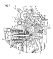
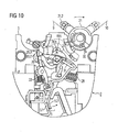
- FIG 1,3,5,7,9
- den Laststrom führenden Abschnitt der erfindungsgemäßen Schaltvorrichtung als Teil eines Schutzschaltgerätes in verschiedenen Funktionsstellungen;
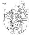
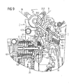
- FIG 2,4,6,8,10
- den Strom rückführenden Abschnitt der erfindungsgemäßen Schaltvorrichtung als Teil eines Schutzschaltgerätes in verschiedenen Funktionsstellungen; und
- FIG 11
- mögliche Positionen des ortsveränderlichen Betätigungselements als Teil des Schaltschlosses der Schaltvorrichtung.
- In den
FIG 1 bis 11 ist eine Schaltvorrichtung 1 als Teil eines Schaltgerätes 2 gezeigt. Das Schaltgerät 2 ist als Leitungsschutzschalter ausgeführt und als solches für den Einsatz in einem Wechselstromnetz geeignet. Das Schaltgerät 2 weist eine Gehäusebreite von 18 mm auf, was einer so genannten Teilungseinheit auf dem Gebiet der Reiheneinbaugeräte entspricht. In der Teilungseinheit sind sowohl Komponenten des Laststrom führenden Teils, insbesondere eines Phasenleiters oder auch L-Teils, als auch Komponenten des Strom rückführenden Teils, insbesondere eines Neutralleiters oder auch N-Teils, der Vorrichtung untergebracht; dabei sind die jeweiligen Schaltmechanik- und Schaltkontakt-Elemente der beiden Vorrichtungsteile spiegelverkehrt zueinander in einem Gehäuse 3 isoliert voneinander angeordnet. Neben einem Gehäuse mit einer Teilungseinheit ist auch ein Gehäuse mit zwei Teilungseinheiten mit einer Gehäusebreite von 36 mm möglich, welches bis zu vier Vorrichtungsteile bzw. zu schaltende Drehstrom-Strompfade, insbesondere mit drei Phasenleitern und einem Neutralleiter, umfasst. - Die in dem Schaltgerät 2 angeordnete Schaltvorrichtung 1 ist mit einer ersten Schaltstelle 4 und mit einer weiteren Schaltstelle 5 versehen. Die beiden Schaltstellen 4;5 weisen ihrerseits jeweils einen feststehenden Kontaktträger 4.1;5.1 und einen beweglichen Kontaktträger 4.2;5.2 auf. Die Schaltvorrichtung 1 umfasst zudem eine gemeinsame Schaltmechanik zur Steuerung der Bewegungsabläufe der beiden beweglichen Kontaktträger 4.2;5.2. Auch ein Auslöser 6 ist Bestandteil der Schaltvorrichtung 1, der zum Öffnen der Schaltstellen 4;5 bestimmt ist.
- Wie in den
FIG 1 und2 gezeigt, ist der feststehende Kontaktträger 4.1 im Strompfad des Neutralleiters näher an seinem beweglichen Kontaktträger 4.2 im Strompfad des Neutralleiters angeordnet als der feststehende Kontaktträger 5.1 an seinem beweglichen Kontaktträger 5.2 im Strompfad des Phasenleiters. Bei einer Auslösung des Schaltgerätes 2 wird folglich erst im Nachgang an die Trennung der Schaltstelle 4 des Phasenleiters die Trennung der Schaltstelle 5 des Neutralleiters eingeleitet. Beim Wiedereinschalten des Schaltgerätes 2 wird, bedingt durch den geringeren Abstand zwischen dem feststehenden Kontaktträger 4.1 und dem beweglichen Kontaktträger 4.2 im Strompfad des Neutralleiters, die Schaltstelle 4 vor der Schaltstelle 5 geschlossen. Zwischen den beiden Vorrichtungsteilen ist eine elektrisch isolierende Trennwand 8 als Teil des Gehäuses 3 vorgesehen, so dass die erste und die weitere Schaltstelle 4;5 galvanisch voneinander getrennt sind. Die Isolationstrennplatte 8 ist hierbei mit zwei Griffaussparungen versehen, welche einen ausreichenden Freiraum für die Platzierung des Griffs 21 bieten. Durch einen spiegelbildlich versetzten Griff 21, der in der zweiten Griffaussparung angeordnet ist, lassen sich der Gehäusedeckel und die Gehäuseschale auf der jeweils anderen Geräteseite montieren; weitere angepasste Geräteteile lassen sich demzufolge vermeiden. - Der Auslöser 6 arbeitet nach dem elektromagnetischen Funktionsprinzip unter Einsatz eines Ankers 6.1, einer Spule 6.2 und eines Jochs 6.3, welche zu einem Kurzschlussauslöser angeordnet sind; hierbei ist der als Tauchanker ausgeführte Anker 6.1 innerhalb der wendelförmigen Spule 6.2 angeordnet, welche von dem Joch 6.3 in L-Form an einer Stirnseite und an einer Längsseite eingefasst ist. Der Anker 6.1 weist einen Stößel 7 auf, der in einer Öffnung des kurzen L-Schenkels des Jochs 6.3 geführt ist. Um die Schaltvorrichtung 1 in den Bereitschaftsmodus zu versetzten muss das Betätigungselement 21 gemäß der
FIG 1 ,3 ,5 für den L-Teil von seiner AUS-Stellung 10 in seine EIN-Stellung 9 verschwenkt werden. Das gleiche gilt sinngemäß für den N-Teil gemäßFIG 2 ,4 ,6 , dessen Bauteile über den auch auf der Geräteseite des Neutralleiters wirkenden Antriebsbügel 20 mitgeführt werden. Dabei kommt eine ausgesprochen platzsparende Bauteilanordnung zum Einsatz, die sich dadurch auszeichnet, dass die beiden Schaltschlösser des L-Teils und des N-Teils in etwas im gleichen Gerätebereich nebeneinander in der vorhandenen Gerätebreite untergebracht sind und deren Komponenten entgegengesetzte Drehrichtungen aufweisen. - Im Falle eines auftretenden Kurzschlusses in dem durch die Schaltvorrichtung 1 geschützten Stromkreis fließt ein Kurzschlussstrom I. Die Schaltvorrichtung 1 befindet sich hierbei in der EIN-Stellung 9 gemäß
FIG 5 und6 . Der Kurzschlussstrom I wird über eine Eingangsklemme des L-Teils an die Auslösespule 6.2 bis hin zu dem Festkontaktträger 4.1 und damit zu einem darauf angeordneten Festkontakt 4.3 geleitet. Von dem Festkontakt 4.3 wird der Strom I weitergeführt über einen korrespondierenden Bewegkontakt 4.4, der auf dem beweglichen Kontaktträger 4.2 platziert ist. Der bewegliche Kontaktträger 4.2 ist seinerseits mit einem flexiblen Leiter 13, insbesondere Litze, verbunden, der wiederum an einem thermischen Auslöser 14 angeordnet ist. Der Kurzschlussstrom I fließt demnach über den beweglichen Kontaktträger 4.2, den flexiblen Leiter 13 und auch über den thermischen Auslöser 14 bis hin zu einer Abgangsklemme, welche durch ein Verbindungsmittel mit dem Trägerelement des thermischen Auslösers 14 gekoppelt ist. - Bedingt durch den Kurzschlussstrom I wird ein Magnetfeld erzeugt, das den Anker 6.1 dazu veranlasst, in Richtung eines Auslösehebels 17 im Strompfad des Phasenleiters L weiter in die Auslösespule 6.2 gemäß
FIG 7 einzutauchen. Der an dem Anker 6.1 befindliche Stößel 7 schlägt in Folge dessen an dem Krafteinleitungsende 17.1 des drehbeweglich gelagerten Auslösehebels 17 an. Der Auslösehebel 17 wird daraufhin entgegen dem Uhrzeigersinn aus seiner Verklinkungsstellung gedreht. Die Verklinkungsstellung ist gebildet durch das Verklinkungsende 17.2 des Auslösehebels 17 und einer drehbeweglich gelagerten und in ihrer Lagerung längsverschieblichen Klinke 18. Im vorliegenden Ausführungsbeispiel weist die Klinke 18 einen Rastfortsatz 18.1 auf, der in der Verklinkungsstellung auf einem Absatz 17.3 des Auslösehebels 17 aufliegt. - Die Klinke 18 ist mittelbar über eine Feder 19, insbesondere Druckfeder, vorgespannt und neigt dazu, entgegen dem Uhrzeigersinn zu drehen. Das Drehlager der Klinke 18 ist durch ein Ende 20.1 eines Antriebsbügels 20 gegeben, der eine U-Form aufweist. Das andere Ende 20.2 des Antriebsbügels 20 ist in einer Ausnehmung 21.1 einer Knebelwalze 21 angeordnet. Die Klinke 18 ist darüber hinaus an dem dem Rastfortsatz 18.1 gegenüberliegenden Ende 18.2 mit einem U-förmigen Koppelbügel 22 verbunden, der an seinem einen Ende 22.1 in einer Aufnahme 18.3 der Klinke 18 drehbeweglich gelagert ist. Das andere Ende 22.2 des Koppelbügels 22 bildet ein Drehlager für das Lagerende 4.5 des beweglichen Kontaktträgers 4.2, welches zudem in einer Gehäusekulisse 3.1 geführt ist. Der bewegliche Kontaktträger 4.2 steht im Anschluss an seine Lagerstelle in einer Wirkverbindung mit der Feder 19, die zum einen zur Herstellung des Kontaktdrucks an der einen Schaltstelle 4 und zum anderen zur Vorspannung der als Schaltschloss ausgeführten Schaltmechanik verantwortlich ist. Als Dreh- bzw. Umlenkpunkt für den beweglichen Kontaktträger 4.2 dient ein gehäusefester Bolzen 3.2.
- Sobald gemäß
FIG 7 und9 der Auslösehebel 17 die Klinke 18 aus der Verklinkungsstelle freigibt, setzt die Feder 19 ihre gespeicherte Energie frei, indem der bewegliche Kontaktträger 4.2 mit dem Bolzen 3.2 als Dreh- bzw. Umlenkpunkt entgegen dem Uhrzeigersinn einerseits mit seinem Kontaktende 4.6 von dem Festkontakt 4.3 und andererseits mit seinem Lagerende 4.5 von der Feder 19 in Richtung der Klinke 18 weggeschwenkt wird. Hierbei tendiert der Koppelbügel 22 dazu, sich im Uhrzeigersinn zu drehen, wobei die dabei auf die Klinke 18 einwirkende Hebelkraft zur Weiterdrehung der Klinke 18 und des beweglichen Kontaktträgers 4.2 führt, bis ein an der Klinke 18 angeformter Exzenter 18.4 an einem Ausleger 23.1 eines Mitnehmers 23 unter Anpressdruck zum Anliegen kommt. - Durch das schlagartige Aufreißen der ersten Schaltstelle 4 unter Kurzschlussstrom-Belastung gemäß
FIG 7 bildet sich zwischen dem Kontaktpaar 4.3;4.4 ein Lichtbogen, der zu seiner Löschung über zueinander trichterförmig angeordnete Lichtbogen-Leitschienen in eine Lichtbogen-Löschkammer 25 getrieben wird. Sofern der Lichtbogen wünschgemäß erloschen und damit der Stromfluss unterbrochen ist, also die Gefahr einer Lasttrennung der weiteren Schaltstelle 5, insbesondere des N-Teils N, nicht mehr vorliegt, kann der Anker 6.1 in seine Ausgangsstellung zurückkehren. - In der Folge wirkt der an dem Ausleger 23.1 unter Anpressdruck zum Anliegen gekommene Klinkenexzenter 18.4 auf den über eine Kulisse geführten Mitnehmer 23 ein, der mit einem Übertragungselement 23.2 versehen ist, das sich auf die Seite des N-Teils N gemäß der
FIG 8 und10 erstreckt. Das Übertragungselement 23.2 wirkt dabei vorrangig im N-Teil N auf eine weitere Fahne 26.2 des Auslösehebels 26 an dessen Verklinkungsende 26.3 derart ein, dass sich dieser entgegen dem Uhrzeigersinn bewegt. - Gleiches gilt für die baugleiche Anordnung in dem L-Teil L, sofern sich die dortige Fahne 17.4 gemäß
FIG 7 und9 noch in Reichweite des Mitnehmers 23 befindet. Hierbei wird die Kraft der Feder 19 des L-Teils L durch Verschiebung des Übertragungselements 23.2 in Richtung des Verklinkungsendes 26.3 des Auslösehebels 26 des N-Teils N weitergegeben, wodurch das Verklinkungsende 26.3 außer Eingriff mit der Klinke 27 des N-Teils N gebracht wird. Im Anschluss daran erfolgt auf der Seite des N-Teils N ein Bewegungsablauf des Schaltschlossbereichs, der dem des Schaltschlossbereichs auf der Seite des L-Teils L entspricht. Die Energie der Feder 28 des N-Teils N wird in der Folge freigesetzt und führt zu einer Öffnung der weiteren Schaltstelle 5, indem der bewegliche Kontaktträger 5.2 von seiner Schließstellung in seine Öffnungsstellung entgegen dem Uhrzeigersinn verschwenkt, so dass schließlich das Schaltschloss vollkommen ausgelöst ist und beide Schaltstellen 4;5 gemäß derFIG 1 bzw. 2 unterbrochen sind. - Im Falle einer damit einhergehenden Drehbewegung der freigegebenen Klinken 18;27 führt dies zudem zu einer Längsverschiebung des Klinkendrehlagers 20.1 in einer Führungsnut 18.5, wodurch die Knebelwalze 21 mit Unterstützung eines Federelements 30 z.B. zusammen mit dem daran angeordneten Betätigungsknebel 21.2 von der EIN-Stellung 9 in die AUS-Stellung 10 verschwenkt; damit wird auch außerhalb des Gehäuses 3 der Schaltstellungswechsel gemäß der
FIG 1 und2 angezeigt. Zum Wiedereinschalten des Gerätes 2 bei fehlerfreiem Stromkreis kann der Knebel 21.2 der Antriebswalze 21 manuell oder beispielsweise per Fernantrieb von der AUS-Stellung 10 in die EIN-Stellung 9 bewegt werden, so dass die Schaltmechanik erneut vorgespannt ist und beide Klinken 18;27 wieder auf dem jeweiligen Auslösehebel 17;26 zum Anliegen kommen. - In
FIG 11 ist die Schaltvorrichtung 1 als Teil eines Leitungsschutzschalters gezeigt, bei der unterschiedliche Positionen des Griffs 21 in einem bestimmten Betätigungsbereich möglich sind. Bei herkömmlichen Schaltvorrichtungen bestimmen die Griffposition und die Lage des Antriebsbügels 20 einen Abstand A und damit die Verklinkungskraft, so dass eine Veränderung der Griffposition nicht ohne einen hohen konstruktiven Aufwand möglich ist. Der Abstand A bewirkt in einer relativ kleinen Dimension eine kleine Verklinkungskraft, damit das jeweilige Auslöseelement, beispielsweise elektromagnetischer Auslöser oder Thermo-Bimetall-Auslöser, nur eine geringe Verklinkungskraft bzw. Reibkraft überwinden muss; hierbei entsteht eine Kraftuntersetzung. - Um eine Entkopplung des Abstands A von der Griffposition zu erreichen, werden die Klinken 18;27 gemäß den
FIG 1 bis 10 auf einer gehäusefesten Bahn 18.5 geführt. Der Abtriebsbügel 20 hat somit nur noch die Aufgabe, die Klinken 18;27 auf dieser Bahn 18.5 zu bewegen. Der Abstand A wird folglich ausschließlich von der Position der Klinken 18;27 und der Position des Koppelbügels 12 bestimmt. Für die Funktion des Schaltschlosses ist es maßgeblich, dass der Klinkenlagerpunkt 20.1 von dem Endpunkt E1 zum Endpunkt E2 verschoben wird, wodurch sich der Abstand A einstellt. - Die zuvor erläuterte erfindungsgemäße Lösung mit einem versetzbaren Griffelement kann wie folgt zusammengefasst werden:
- Um eine Schaltvorrichtung 1 zu schaffen, die bei gleichbleibender Funktionscharakteristik ein ortsveränderliches Betätigungselement 21 aufweist, ist zum einen eine drehbare Klinke 18 zur Verklinkung oder Entklinkung derselben an einem drehbaren Auslösehebel 17 und zum anderen ein Antriebsbügel 20, der sowohl an dem Betätigungselement 21 als auch an der Klinke 18 drehbar angeordnet ist, vorgesehen, wobei einerseits ein drehbarer Kontaktträger 4.2 als Teil der Schaltstelle 4 zur Kontaktierung eines feststehenden Kontaktträgers 4.1 und andererseits ein Koppelbügel 22 vorgesehen ist, der sowohl an dem verschwenkbaren Kontaktträger 4.2 als auch an der Klinke 18 drehbar angeordnet ist, wobei die Klinke 18 an ihrem Drehpunkt 20.1 derart verschiebbar ist, dass die Distanz zwischen dem Betätigungselement 21 und der Klinke 18 in Abhängigkeit der Stellung des Betätigungselements 21 variiert.
Claims (12)
- Schaltvorrichtung (1) mit einem drehbeweglichen Betätigungselement (21) zum mittelbaren Schließen oder Trennen einer Schaltstelle (4;5), und mit einer drehbeweglichen Klinke (18;27) zur Verklinkung oder Entklinkung derselben an einem Auslösehebel (17;26), und mit einem Antriebselement, insbesondere Antriebsbügel (20), und mit einem Kontaktträger (4.2;5.2), der als Teil der Schaltstelle (4;5) zur Kontaktierung eines feststehenden Kontaktträgers (4.1;5.1) dient, und mit einem Koppelelement, insbesondere Koppelbügel (22;31), der sowohl an dem Kontaktträger (4.2;5.2) als auch an der Klinke (18;27) drehbeweglich angeordnet ist, dadurch gekennzeichnet, dass der Auslösehebel (17;26) drehbeweglich ausgebildet ist, dass das Antriebselement, insbesondere der Antriebsbügel (20), sowohl an dem Betätigungselement (21) als auch an der Klinke (18;27) drehbeweglich angeordnet ist, dass der Kontaktträger (4.2;5.2) drehbeweglich ausgebildet ist und dass die Klinke (18;27) an ihrem Drehpunkt (20.1) derart verschiebbar ist, dass die Distanz zwischen dem Betätigungselement (21) und der Klinke (18;27) in Abhängigkeit der Stellung des Betätigungselements (21) variiert.
- Schaltvorrichtung (1) nach Anspruch 1, bei der zumindest das Betätigungselement (21), der Antriebsbügel(20), die Klinke (18;27), der Koppelbügel(22;31), der Auslösehebel (17;26) und der bewegliche Kontaktträger (4.2;5.2) Teile eines Schaltschlosses sind.
- Schaltvorrichtung (1) nach Anspruch 1 oder 2, bei der das Betätigungselement (21) einen Schaltknebel (21.2) und eine Schaltwalze (21.3) aufweist.
- Schaltvorrichtung (1) nach Anspruch 1 oder 2, bei welcher der Antriebsbügel (20) eine U-Form aufweist, wovon das eine Ende des Antriebsbügels (20) als Drehlager des Betätigungselements und das weitere Ende des Antriebsbügels als Drehlager (20.1) der Klinke (18;27) ausgeführt ist.
- Schaltvorrichtung (1) nach Anspruch 4, bei welcher das weitere Ende des Antriebsbügels (20) auch als Führungsmittel der Klinke (18;27) ausgeführt ist.
- Schaltvorrichtung (1) nach Anspruch 1 oder 2, bei der die Klinke (18;27) in einer Kulisse (18.5), insbesondere auf einer geradlinigen oder gekrümmten Bahn, verschiebbar ist.
- Schaltvorrichtung (1) nach Anspruch 6, bei der die Kulisse (18.5) als Langloch in einem Isolationstrennstück (8) ausgeführt ist, das einen ersten Strompfad (L) von einem weiteren Strompfad (N) elektrisch trennt.
- Schaltvorrichtung (1) nach einem der Ansprüche 1 bis 3, bei welcher das Betätigungselement (21) und/oder der Auslösehebel (17;26) und/oder der bewegliche Kontaktträger (4.2;5.2) mittels Federkraft beaufschlagt sind.
- Schaltvorrichtung (1) nach Anspruch 8, bei der eine Grifffeder (30) das Betätigungselement (21), eine Verklinkungsfeder (32;33) den Auslösehebel (17;26) und eine Kontaktdruckfeder (19;28) den beweglichen Kontaktträger (4.2;5.2) jeweils mit Federkraft beaufschlagen.
- Schaltvorrichtung (1) nach Anspruch 1 oder 2, bei der mittels des Antriebsbügels (20) neben der einen Klinke (18) des einen Strompfads (L) eine weitere Klinke (27) des weiteren Strompfads (N) antreibbar ist, die zueinander entgegengesetzte Drehrichtungen aufweisen.
- Schaltvorrichtung (1) nach Anspruch 10, bei der die weitere Klinke (27) als Teil eines weiteren Schaltschlosses mit einem weiteren Auslösehebel (26), einem weiteren Koppelbügel (31) und mit einem weiteren drehbeweglichen Kontaktträger (5.2) in einer Wirkverbindung steht.
- Schaltgerät, insbesondere Schutzschaltgerät bzw. Leitungsschutzschalter, mit einer Schaltvorrichtung (1) nach Anspruch 1.
Applications Claiming Priority (1)
| Application Number | Priority Date | Filing Date | Title |
|---|---|---|---|
| DE102006036187A DE102006036187A1 (de) | 2006-08-01 | 2006-08-01 | Schaltvorrichtung mit Betätigungselement |
Publications (2)
| Publication Number | Publication Date |
|---|---|
| EP1884976A1 EP1884976A1 (de) | 2008-02-06 |
| EP1884976B1 true EP1884976B1 (de) | 2011-11-16 |
Family
ID=38544059
Family Applications (1)
| Application Number | Title | Priority Date | Filing Date |
|---|---|---|---|
| EP07112882A Active EP1884976B1 (de) | 2006-08-01 | 2007-07-20 | Schaltvorrichtung mit Betätigungselement |
Country Status (5)
| Country | Link |
|---|---|
| EP (1) | EP1884976B1 (de) |
| CN (1) | CN101118821B (de) |
| AT (1) | ATE534134T1 (de) |
| DE (1) | DE102006036187A1 (de) |
| ES (1) | ES2375408T3 (de) |
Families Citing this family (5)
| Publication number | Priority date | Publication date | Assignee | Title |
|---|---|---|---|---|
| DE102010032556A1 (de) | 2010-07-29 | 2012-02-02 | Siemens Aktiengesellschaft | Schaltgerät mit zwangsgesteuertem Teleskopgriff |
| JP5620768B2 (ja) * | 2010-09-21 | 2014-11-05 | パナソニックエコソリューションズ電路株式会社 | 回路遮断器 |
| CN103632900B (zh) * | 2012-08-22 | 2016-04-13 | 西门子公司 | 复位装置及剩余电流动作断路器 |
| FR3121272B1 (fr) | 2021-03-26 | 2023-03-31 | Schneider Electric Ind Sas | Dispositif de protection électrique et tableau électrique comprenant un tel dispositif de protection |
| FR3123140B1 (fr) | 2021-05-20 | 2023-05-26 | Schneider Electric Ind Sas | Dispositif de protection électrique |
Family Cites Families (7)
| Publication number | Priority date | Publication date | Assignee | Title |
|---|---|---|---|---|
| DE1563781C3 (de) * | 1966-12-08 | 1973-10-31 | Siemens Ag, 1000 Berlin U. 8000 Muenchen | Leitungsschutzschalter |
| CH618288A5 (de) * | 1977-08-05 | 1980-07-15 | Weber Ag Fab Elektro | |
| IT1195443B (it) | 1983-10-13 | 1988-10-19 | Ave Spa | Interruttore differenziale perfezionato di ridotto ingombro |
| CN85103421B (zh) * | 1985-04-17 | 1987-11-04 | 三菱电机株式会社 | 断路器 |
| DE19716380C1 (de) * | 1997-04-18 | 1998-10-08 | Siemens Ag | Elektromagnetisches Schaltgerät |
| DE19919417A1 (de) * | 1999-04-28 | 2000-11-02 | Siemens Ag | Schutzschalteinrichtung |
| US6812423B1 (en) * | 2003-10-24 | 2004-11-02 | Eaton Corporation | Circuit breaker including lock for operating mechanism linkage |
-
2006
- 2006-08-01 DE DE102006036187A patent/DE102006036187A1/de not_active Withdrawn
-
2007
- 2007-07-20 AT AT07112882T patent/ATE534134T1/de active
- 2007-07-20 EP EP07112882A patent/EP1884976B1/de active Active
- 2007-07-20 ES ES07112882T patent/ES2375408T3/es active Active
- 2007-07-31 CN CN2007101376892A patent/CN101118821B/zh active Active
Also Published As
| Publication number | Publication date |
|---|---|
| DE102006036187A1 (de) | 2008-02-07 |
| CN101118821B (zh) | 2012-06-27 |
| ES2375408T3 (es) | 2012-02-29 |
| CN101118821A (zh) | 2008-02-06 |
| ATE534134T1 (de) | 2011-12-15 |
| EP1884976A1 (de) | 2008-02-06 |
Similar Documents
| Publication | Publication Date | Title |
|---|---|---|
| EP1884976B1 (de) | Schaltvorrichtung mit Betätigungselement | |
| EP0111662A1 (de) | Elektrischer Schalter | |
| EP0144799A2 (de) | Leitungsschutzschalter | |
| DE69930795T2 (de) | Schutzschalter | |
| EP0120836A1 (de) | Elektrischer geräteschutzschalter. | |
| DE2719052A1 (de) | Mehrpoliger schalter | |
| DE68920538T2 (de) | Ferngesteuerter Schutzschalter. | |
| DE4233918B4 (de) | Elektrischer Schalter mit Stromüberwachung | |
| EP1735803B1 (de) | Schaltvorrichtung | |
| DE19703977C1 (de) | Schaltgerät mit Schnelleinschaltung | |
| EP1284494B1 (de) | Schaltschloss für ein elektrisches Schaltgerät, insbesondere für einen Motorschutzschalter | |
| EP0243648B1 (de) | Elektrischer Schutzschalter | |
| DE721862C (de) | Selbstschalter, insbesondere Trennschutzschalter | |
| EP0820084B1 (de) | Betätigungsvorrichtung für Leistungsschaltgeräte | |
| DE102006036194B4 (de) | Schaltvorrichtung mit Schaltstellenpaar | |
| EP0849759B1 (de) | Installationsschaltgerät | |
| EP0147629B1 (de) | Schutzschalter | |
| EP1884975B1 (de) | Schaltvorrichtung | |
| EP0851449B1 (de) | Installationsschaltgerät | |
| DE68928206T2 (de) | Betätigungsmechanismus für einen mehrpoligen Fehlerstromschutzschalter mit drehbarer Schaltwelle | |
| AT404647B (de) | Elektrischer schutzschalter | |
| EP1709659B1 (de) | Elektromechanischer schalter | |
| EP0491250A2 (de) | Installationsgerät | |
| DE102005046640B4 (de) | Elektrisches Installationsgerät | |
| DE1003327B (de) | Installationsselbstschalter in Schmalbauform mit magnetischer und thermischer Ausloesung und einem oder mehreren abschaltbaren Hilfskontakten fuer allgemeine Leitungsschutz- oder Spezialzwecke |
Legal Events
| Date | Code | Title | Description |
|---|---|---|---|
| PUAI | Public reference made under article 153(3) epc to a published international application that has entered the european phase |
Free format text: ORIGINAL CODE: 0009012 |
|
| AK | Designated contracting states |
Kind code of ref document: A1 Designated state(s): AT BE BG CH CY CZ DE DK EE ES FI FR GB GR HU IE IS IT LI LT LU LV MC MT NL PL PT RO SE SI SK TR |
|
| AX | Request for extension of the european patent |
Extension state: AL BA HR MK YU |
|
| 17P | Request for examination filed |
Effective date: 20080804 |
|
| AKX | Designation fees paid |
Designated state(s): AT BE BG CH CY CZ DE DK EE ES FI FR GB GR HU IE IS IT LI LT LU LV MC MT NL PL PT RO SE SI SK TR |
|
| GRAP | Despatch of communication of intention to grant a patent |
Free format text: ORIGINAL CODE: EPIDOSNIGR1 |
|
| GRAS | Grant fee paid |
Free format text: ORIGINAL CODE: EPIDOSNIGR3 |
|
| GRAA | (expected) grant |
Free format text: ORIGINAL CODE: 0009210 |
|
| AK | Designated contracting states |
Kind code of ref document: B1 Designated state(s): AT BE BG CH CY CZ DE DK EE ES FI FR GB GR HU IE IS IT LI LT LU LV MC MT NL PL PT RO SE SI SK TR |
|
| REG | Reference to a national code |
Ref country code: GB Ref legal event code: FG4D Free format text: NOT ENGLISH |
|
| REG | Reference to a national code |
Ref country code: CH Ref legal event code: EP |
|
| REG | Reference to a national code |
Ref country code: IE Ref legal event code: FG4D Free format text: LANGUAGE OF EP DOCUMENT: GERMAN |
|
| REG | Reference to a national code |
Ref country code: DE Ref legal event code: R096 Ref document number: 502007008677 Country of ref document: DE Effective date: 20120119 |
|
| REG | Reference to a national code |
Ref country code: NL Ref legal event code: VDEP Effective date: 20111116 Ref country code: ES Ref legal event code: FG2A Ref document number: 2375408 Country of ref document: ES Kind code of ref document: T3 Effective date: 20120229 |
|
| LTIE | Lt: invalidation of european patent or patent extension |
Effective date: 20111116 |
|
| PG25 | Lapsed in a contracting state [announced via postgrant information from national office to epo] |
Ref country code: LT Free format text: LAPSE BECAUSE OF FAILURE TO SUBMIT A TRANSLATION OF THE DESCRIPTION OR TO PAY THE FEE WITHIN THE PRESCRIBED TIME-LIMIT Effective date: 20111116 Ref country code: IS Free format text: LAPSE BECAUSE OF FAILURE TO SUBMIT A TRANSLATION OF THE DESCRIPTION OR TO PAY THE FEE WITHIN THE PRESCRIBED TIME-LIMIT Effective date: 20120316 |
|
| PG25 | Lapsed in a contracting state [announced via postgrant information from national office to epo] |
Ref country code: LV Free format text: LAPSE BECAUSE OF FAILURE TO SUBMIT A TRANSLATION OF THE DESCRIPTION OR TO PAY THE FEE WITHIN THE PRESCRIBED TIME-LIMIT Effective date: 20111116 Ref country code: SE Free format text: LAPSE BECAUSE OF FAILURE TO SUBMIT A TRANSLATION OF THE DESCRIPTION OR TO PAY THE FEE WITHIN THE PRESCRIBED TIME-LIMIT Effective date: 20111116 Ref country code: GR Free format text: LAPSE BECAUSE OF FAILURE TO SUBMIT A TRANSLATION OF THE DESCRIPTION OR TO PAY THE FEE WITHIN THE PRESCRIBED TIME-LIMIT Effective date: 20120217 Ref country code: PL Free format text: LAPSE BECAUSE OF FAILURE TO SUBMIT A TRANSLATION OF THE DESCRIPTION OR TO PAY THE FEE WITHIN THE PRESCRIBED TIME-LIMIT Effective date: 20111116 Ref country code: SI Free format text: LAPSE BECAUSE OF FAILURE TO SUBMIT A TRANSLATION OF THE DESCRIPTION OR TO PAY THE FEE WITHIN THE PRESCRIBED TIME-LIMIT Effective date: 20111116 Ref country code: PT Free format text: LAPSE BECAUSE OF FAILURE TO SUBMIT A TRANSLATION OF THE DESCRIPTION OR TO PAY THE FEE WITHIN THE PRESCRIBED TIME-LIMIT Effective date: 20120316 Ref country code: NL Free format text: LAPSE BECAUSE OF FAILURE TO SUBMIT A TRANSLATION OF THE DESCRIPTION OR TO PAY THE FEE WITHIN THE PRESCRIBED TIME-LIMIT Effective date: 20111116 |
|
| REG | Reference to a national code |
Ref country code: IE Ref legal event code: FD4D |
|
| PG25 | Lapsed in a contracting state [announced via postgrant information from national office to epo] |
Ref country code: CY Free format text: LAPSE BECAUSE OF FAILURE TO SUBMIT A TRANSLATION OF THE DESCRIPTION OR TO PAY THE FEE WITHIN THE PRESCRIBED TIME-LIMIT Effective date: 20111116 |
|
| PG25 | Lapsed in a contracting state [announced via postgrant information from national office to epo] |
Ref country code: SK Free format text: LAPSE BECAUSE OF FAILURE TO SUBMIT A TRANSLATION OF THE DESCRIPTION OR TO PAY THE FEE WITHIN THE PRESCRIBED TIME-LIMIT Effective date: 20111116 Ref country code: CZ Free format text: LAPSE BECAUSE OF FAILURE TO SUBMIT A TRANSLATION OF THE DESCRIPTION OR TO PAY THE FEE WITHIN THE PRESCRIBED TIME-LIMIT Effective date: 20111116 Ref country code: IE Free format text: LAPSE BECAUSE OF FAILURE TO SUBMIT A TRANSLATION OF THE DESCRIPTION OR TO PAY THE FEE WITHIN THE PRESCRIBED TIME-LIMIT Effective date: 20111116 Ref country code: DK Free format text: LAPSE BECAUSE OF FAILURE TO SUBMIT A TRANSLATION OF THE DESCRIPTION OR TO PAY THE FEE WITHIN THE PRESCRIBED TIME-LIMIT Effective date: 20111116 Ref country code: BG Free format text: LAPSE BECAUSE OF FAILURE TO SUBMIT A TRANSLATION OF THE DESCRIPTION OR TO PAY THE FEE WITHIN THE PRESCRIBED TIME-LIMIT Effective date: 20120216 Ref country code: EE Free format text: LAPSE BECAUSE OF FAILURE TO SUBMIT A TRANSLATION OF THE DESCRIPTION OR TO PAY THE FEE WITHIN THE PRESCRIBED TIME-LIMIT Effective date: 20111116 |
|
| PG25 | Lapsed in a contracting state [announced via postgrant information from national office to epo] |
Ref country code: RO Free format text: LAPSE BECAUSE OF FAILURE TO SUBMIT A TRANSLATION OF THE DESCRIPTION OR TO PAY THE FEE WITHIN THE PRESCRIBED TIME-LIMIT Effective date: 20111116 |
|
| PLBE | No opposition filed within time limit |
Free format text: ORIGINAL CODE: 0009261 |
|
| STAA | Information on the status of an ep patent application or granted ep patent |
Free format text: STATUS: NO OPPOSITION FILED WITHIN TIME LIMIT |
|
| 26N | No opposition filed |
Effective date: 20120817 |
|
| REG | Reference to a national code |
Ref country code: DE Ref legal event code: R097 Ref document number: 502007008677 Country of ref document: DE Effective date: 20120817 |
|
| BERE | Be: lapsed |
Owner name: SIEMENS A.G. Effective date: 20120731 |
|
| PG25 | Lapsed in a contracting state [announced via postgrant information from national office to epo] |
Ref country code: MC Free format text: LAPSE BECAUSE OF NON-PAYMENT OF DUE FEES Effective date: 20120731 |
|
| REG | Reference to a national code |
Ref country code: CH Ref legal event code: PL |
|
| GBPC | Gb: european patent ceased through non-payment of renewal fee |
Effective date: 20120720 |
|
| PG25 | Lapsed in a contracting state [announced via postgrant information from national office to epo] |
Ref country code: CH Free format text: LAPSE BECAUSE OF NON-PAYMENT OF DUE FEES Effective date: 20120731 Ref country code: LI Free format text: LAPSE BECAUSE OF NON-PAYMENT OF DUE FEES Effective date: 20120731 Ref country code: GB Free format text: LAPSE BECAUSE OF NON-PAYMENT OF DUE FEES Effective date: 20120720 |
|
| PG25 | Lapsed in a contracting state [announced via postgrant information from national office to epo] |
Ref country code: BE Free format text: LAPSE BECAUSE OF NON-PAYMENT OF DUE FEES Effective date: 20120731 |
|
| PG25 | Lapsed in a contracting state [announced via postgrant information from national office to epo] |
Ref country code: FI Free format text: LAPSE BECAUSE OF FAILURE TO SUBMIT A TRANSLATION OF THE DESCRIPTION OR TO PAY THE FEE WITHIN THE PRESCRIBED TIME-LIMIT Effective date: 20111116 |
|
| PG25 | Lapsed in a contracting state [announced via postgrant information from national office to epo] |
Ref country code: MT Free format text: LAPSE BECAUSE OF FAILURE TO SUBMIT A TRANSLATION OF THE DESCRIPTION OR TO PAY THE FEE WITHIN THE PRESCRIBED TIME-LIMIT Effective date: 20111116 |
|
| REG | Reference to a national code |
Ref country code: AT Ref legal event code: MM01 Ref document number: 534134 Country of ref document: AT Kind code of ref document: T Effective date: 20120731 |
|
| REG | Reference to a national code |
Ref country code: ES Ref legal event code: FD2A Effective date: 20131022 |
|
| PG25 | Lapsed in a contracting state [announced via postgrant information from national office to epo] |
Ref country code: AT Free format text: LAPSE BECAUSE OF NON-PAYMENT OF DUE FEES Effective date: 20120731 |
|
| PG25 | Lapsed in a contracting state [announced via postgrant information from national office to epo] |
Ref country code: TR Free format text: LAPSE BECAUSE OF FAILURE TO SUBMIT A TRANSLATION OF THE DESCRIPTION OR TO PAY THE FEE WITHIN THE PRESCRIBED TIME-LIMIT Effective date: 20111116 |
|
| PG25 | Lapsed in a contracting state [announced via postgrant information from national office to epo] |
Ref country code: ES Free format text: LAPSE BECAUSE OF NON-PAYMENT OF DUE FEES Effective date: 20120721 Ref country code: LU Free format text: LAPSE BECAUSE OF NON-PAYMENT OF DUE FEES Effective date: 20120720 |
|
| PG25 | Lapsed in a contracting state [announced via postgrant information from national office to epo] |
Ref country code: HU Free format text: LAPSE BECAUSE OF FAILURE TO SUBMIT A TRANSLATION OF THE DESCRIPTION OR TO PAY THE FEE WITHIN THE PRESCRIBED TIME-LIMIT Effective date: 20070720 |
|
| REG | Reference to a national code |
Ref country code: FR Ref legal event code: PLFP Year of fee payment: 10 |
|
| REG | Reference to a national code |
Ref country code: FR Ref legal event code: PLFP Year of fee payment: 11 |
|
| REG | Reference to a national code |
Ref country code: FR Ref legal event code: PLFP Year of fee payment: 12 |
|
| P01 | Opt-out of the competence of the unified patent court (upc) registered |
Effective date: 20230512 |
|
| PGFP | Annual fee paid to national office [announced via postgrant information from national office to epo] |
Ref country code: FR Payment date: 20230720 Year of fee payment: 17 |
|
| PGFP | Annual fee paid to national office [announced via postgrant information from national office to epo] |
Ref country code: IT Payment date: 20240725 Year of fee payment: 18 |
|
| PG25 | Lapsed in a contracting state [announced via postgrant information from national office to epo] |
Ref country code: FR Free format text: LAPSE BECAUSE OF NON-PAYMENT OF DUE FEES Effective date: 20240731 |
|
| PGFP | Annual fee paid to national office [announced via postgrant information from national office to epo] |
Ref country code: DE Payment date: 20250919 Year of fee payment: 19 |