EP1884353A1 - Kunststoffverbundfolie - Google Patents
Kunststoffverbundfolie Download PDFInfo
- Publication number
- EP1884353A1 EP1884353A1 EP06405319A EP06405319A EP1884353A1 EP 1884353 A1 EP1884353 A1 EP 1884353A1 EP 06405319 A EP06405319 A EP 06405319A EP 06405319 A EP06405319 A EP 06405319A EP 1884353 A1 EP1884353 A1 EP 1884353A1
- Authority
- EP
- European Patent Office
- Prior art keywords
- layer
- plastic
- metal
- metal foil
- protective layer
- Prior art date
- Legal status (The legal status is an assumption and is not a legal conclusion. Google has not performed a legal analysis and makes no representation as to the accuracy of the status listed.)
- Withdrawn
Links
- 229920003023 plastic Polymers 0.000 title claims abstract description 90
- 239000004033 plastic Substances 0.000 title claims abstract description 90
- 239000002131 composite material Substances 0.000 title claims abstract description 48
- 229910052751 metal Inorganic materials 0.000 claims abstract description 163
- 239000002184 metal Substances 0.000 claims abstract description 163
- 239000010410 layer Substances 0.000 claims abstract description 161
- 239000011888 foil Substances 0.000 claims abstract description 96
- 239000011651 chromium Substances 0.000 claims abstract description 79
- 239000011241 protective layer Substances 0.000 claims abstract description 71
- VYZAMTAEIAYCRO-UHFFFAOYSA-N Chromium Chemical compound [Cr] VYZAMTAEIAYCRO-UHFFFAOYSA-N 0.000 claims abstract description 26
- 229910052804 chromium Inorganic materials 0.000 claims abstract description 24
- 238000000034 method Methods 0.000 claims abstract description 15
- 229920000642 polymer Polymers 0.000 claims abstract description 14
- 239000002985 plastic film Substances 0.000 claims abstract description 10
- 229920006255 plastic film Polymers 0.000 claims abstract description 10
- 238000005289 physical deposition Methods 0.000 claims abstract description 9
- 238000004544 sputter deposition Methods 0.000 claims abstract description 7
- 238000007740 vapor deposition Methods 0.000 claims abstract description 5
- HBBGRARXTFLTSG-UHFFFAOYSA-N Lithium ion Chemical compound [Li+] HBBGRARXTFLTSG-UHFFFAOYSA-N 0.000 claims abstract description 4
- 229910001416 lithium ion Inorganic materials 0.000 claims abstract description 4
- WHXSMMKQMYFTQS-UHFFFAOYSA-N Lithium Chemical compound [Li] WHXSMMKQMYFTQS-UHFFFAOYSA-N 0.000 claims abstract description 3
- 229910052744 lithium Inorganic materials 0.000 claims abstract description 3
- 239000004743 Polypropylene Substances 0.000 claims description 63
- 239000002346 layers by function Substances 0.000 claims description 40
- -1 polyethylene terephthalate Polymers 0.000 claims description 37
- 229920000139 polyethylene terephthalate Polymers 0.000 claims description 27
- 239000005020 polyethylene terephthalate Substances 0.000 claims description 27
- 229910052782 aluminium Inorganic materials 0.000 claims description 24
- 239000004698 Polyethylene Substances 0.000 claims description 23
- XAGFODPZIPBFFR-UHFFFAOYSA-N aluminium Chemical compound [Al] XAGFODPZIPBFFR-UHFFFAOYSA-N 0.000 claims description 22
- 229920001155 polypropylene Polymers 0.000 claims description 22
- 229920002647 polyamide Polymers 0.000 claims description 17
- 239000004952 Polyamide Substances 0.000 claims description 16
- 239000005026 oriented polypropylene Substances 0.000 claims description 15
- 229920000573 polyethylene Polymers 0.000 claims description 7
- QVGXLLKOCUKJST-UHFFFAOYSA-N atomic oxygen Chemical compound [O] QVGXLLKOCUKJST-UHFFFAOYSA-N 0.000 claims description 5
- 239000001301 oxygen Substances 0.000 claims description 5
- 229910052760 oxygen Inorganic materials 0.000 claims description 5
- 229910052719 titanium Inorganic materials 0.000 claims description 5
- 239000010936 titanium Substances 0.000 claims description 5
- 229910052726 zirconium Inorganic materials 0.000 claims description 5
- 238000005566 electron beam evaporation Methods 0.000 claims description 4
- 238000004519 manufacturing process Methods 0.000 claims description 4
- RTAQQCXQSZGOHL-UHFFFAOYSA-N Titanium Chemical compound [Ti] RTAQQCXQSZGOHL-UHFFFAOYSA-N 0.000 claims description 3
- QCWXUUIWCKQGHC-UHFFFAOYSA-N Zirconium Chemical compound [Zr] QCWXUUIWCKQGHC-UHFFFAOYSA-N 0.000 claims description 3
- 238000009832 plasma treatment Methods 0.000 claims description 3
- 238000000151 deposition Methods 0.000 claims description 2
- 238000001771 vacuum deposition Methods 0.000 claims description 2
- 239000010408 film Substances 0.000 description 73
- 229920000098 polyolefin Polymers 0.000 description 13
- 239000000853 adhesive Substances 0.000 description 12
- 230000001070 adhesive effect Effects 0.000 description 12
- 239000000126 substance Substances 0.000 description 12
- 239000012790 adhesive layer Substances 0.000 description 9
- 239000011248 coating agent Substances 0.000 description 6
- 238000000576 coating method Methods 0.000 description 6
- 239000000203 mixture Substances 0.000 description 6
- 238000007789 sealing Methods 0.000 description 6
- XEEYBQQBJWHFJM-UHFFFAOYSA-N Iron Chemical compound [Fe] XEEYBQQBJWHFJM-UHFFFAOYSA-N 0.000 description 5
- 238000003490 calendering Methods 0.000 description 5
- 229920001577 copolymer Polymers 0.000 description 5
- 239000002904 solvent Substances 0.000 description 5
- 239000013077 target material Substances 0.000 description 5
- NBIIXXVUZAFLBC-UHFFFAOYSA-N Phosphoric acid Chemical compound OP(O)(O)=O NBIIXXVUZAFLBC-UHFFFAOYSA-N 0.000 description 4
- 230000004888 barrier function Effects 0.000 description 4
- 238000006243 chemical reaction Methods 0.000 description 4
- 230000007797 corrosion Effects 0.000 description 4
- 238000005260 corrosion Methods 0.000 description 4
- 239000013039 cover film Substances 0.000 description 4
- 239000007789 gas Substances 0.000 description 4
- 150000002739 metals Chemical class 0.000 description 4
- 229920002239 polyacrylonitrile Polymers 0.000 description 4
- 229910000838 Al alloy Inorganic materials 0.000 description 3
- 239000005977 Ethylene Substances 0.000 description 3
- CERQOIWHTDAKMF-UHFFFAOYSA-N Methacrylic acid Chemical compound CC(=C)C(O)=O CERQOIWHTDAKMF-UHFFFAOYSA-N 0.000 description 3
- PXHVJJICTQNCMI-UHFFFAOYSA-N Nickel Chemical compound [Ni] PXHVJJICTQNCMI-UHFFFAOYSA-N 0.000 description 3
- 239000002318 adhesion promoter Substances 0.000 description 3
- 230000000694 effects Effects 0.000 description 3
- 238000010894 electron beam technology Methods 0.000 description 3
- 229910052742 iron Inorganic materials 0.000 description 3
- MWUXSHHQAYIFBG-UHFFFAOYSA-N nitrogen oxide Inorganic materials O=[N] MWUXSHHQAYIFBG-UHFFFAOYSA-N 0.000 description 3
- 230000001681 protective effect Effects 0.000 description 3
- NLHHRLWOUZZQLW-UHFFFAOYSA-N Acrylonitrile Chemical compound C=CC#N NLHHRLWOUZZQLW-UHFFFAOYSA-N 0.000 description 2
- XKRFYHLGVUSROY-UHFFFAOYSA-N Argon Chemical compound [Ar] XKRFYHLGVUSROY-UHFFFAOYSA-N 0.000 description 2
- VGGSQFUCUMXWEO-UHFFFAOYSA-N Ethene Chemical compound C=C VGGSQFUCUMXWEO-UHFFFAOYSA-N 0.000 description 2
- 239000002253 acid Substances 0.000 description 2
- 229910045601 alloy Inorganic materials 0.000 description 2
- 239000000956 alloy Substances 0.000 description 2
- 229910000147 aluminium phosphate Inorganic materials 0.000 description 2
- 229910052802 copper Inorganic materials 0.000 description 2
- 239000010949 copper Substances 0.000 description 2
- 238000007766 curtain coating Methods 0.000 description 2
- 230000032798 delamination Effects 0.000 description 2
- 238000001125 extrusion Methods 0.000 description 2
- 239000012939 laminating adhesive Substances 0.000 description 2
- 238000003475 lamination Methods 0.000 description 2
- 238000000465 moulding Methods 0.000 description 2
- 229910052759 nickel Inorganic materials 0.000 description 2
- 229920000728 polyester Polymers 0.000 description 2
- 239000012173 sealing wax Substances 0.000 description 2
- 238000000926 separation method Methods 0.000 description 2
- 239000003440 toxic substance Substances 0.000 description 2
- KXGFMDJXCMQABM-UHFFFAOYSA-N 2-methoxy-6-methylphenol Chemical compound [CH]OC1=CC=CC([CH])=C1O KXGFMDJXCMQABM-UHFFFAOYSA-N 0.000 description 1
- IJGRMHOSHXDMSA-UHFFFAOYSA-N Atomic nitrogen Chemical compound N#N IJGRMHOSHXDMSA-UHFFFAOYSA-N 0.000 description 1
- 229920001824 Barex® Polymers 0.000 description 1
- RYGMFSIKBFXOCR-UHFFFAOYSA-N Copper Chemical compound [Cu] RYGMFSIKBFXOCR-UHFFFAOYSA-N 0.000 description 1
- CWYNVVGOOAEACU-UHFFFAOYSA-N Fe2+ Chemical compound [Fe+2] CWYNVVGOOAEACU-UHFFFAOYSA-N 0.000 description 1
- KRHYYFGTRYWZRS-UHFFFAOYSA-N Fluorane Chemical compound F KRHYYFGTRYWZRS-UHFFFAOYSA-N 0.000 description 1
- 229910000831 Steel Inorganic materials 0.000 description 1
- BAPJBEWLBFYGME-UHFFFAOYSA-N acrylic acid methyl ester Natural products COC(=O)C=C BAPJBEWLBFYGME-UHFFFAOYSA-N 0.000 description 1
- 150000001336 alkenes Chemical class 0.000 description 1
- 239000004411 aluminium Substances 0.000 description 1
- 229910052786 argon Inorganic materials 0.000 description 1
- 229910052793 cadmium Inorganic materials 0.000 description 1
- 150000001844 chromium Chemical class 0.000 description 1
- 229910000151 chromium(III) phosphate Inorganic materials 0.000 description 1
- IKZBVTPSNGOVRJ-UHFFFAOYSA-K chromium(iii) phosphate Chemical compound [Cr+3].[O-]P([O-])([O-])=O IKZBVTPSNGOVRJ-UHFFFAOYSA-K 0.000 description 1
- 238000005253 cladding Methods 0.000 description 1
- 230000006735 deficit Effects 0.000 description 1
- 238000005137 deposition process Methods 0.000 description 1
- 230000001066 destructive effect Effects 0.000 description 1
- WMYWOWFOOVUPFY-UHFFFAOYSA-L dihydroxy(dioxo)chromium;phosphoric acid Chemical compound OP(O)(O)=O.O[Cr](O)(=O)=O WMYWOWFOOVUPFY-UHFFFAOYSA-L 0.000 description 1
- 239000003792 electrolyte Substances 0.000 description 1
- 238000001704 evaporation Methods 0.000 description 1
- 230000008020 evaporation Effects 0.000 description 1
- 238000007765 extrusion coating Methods 0.000 description 1
- 229910052733 gallium Inorganic materials 0.000 description 1
- 229910052732 germanium Inorganic materials 0.000 description 1
- 229910052737 gold Inorganic materials 0.000 description 1
- 239000010931 gold Substances 0.000 description 1
- 239000008187 granular material Substances 0.000 description 1
- 229910052735 hafnium Inorganic materials 0.000 description 1
- 229910000040 hydrogen fluoride Inorganic materials 0.000 description 1
- 230000001771 impaired effect Effects 0.000 description 1
- 229910052738 indium Inorganic materials 0.000 description 1
- 238000003780 insertion Methods 0.000 description 1
- 230000037431 insertion Effects 0.000 description 1
- 238000005304 joining Methods 0.000 description 1
- 229910052745 lead Inorganic materials 0.000 description 1
- 239000000463 material Substances 0.000 description 1
- 150000007522 mineralic acids Chemical class 0.000 description 1
- 229910052750 molybdenum Inorganic materials 0.000 description 1
- 239000005022 packaging material Substances 0.000 description 1
- 238000004806 packaging method and process Methods 0.000 description 1
- 229910052763 palladium Inorganic materials 0.000 description 1
- KDLHZDBZIXYQEI-UHFFFAOYSA-N palladium Substances [Pd] KDLHZDBZIXYQEI-UHFFFAOYSA-N 0.000 description 1
- 230000002093 peripheral effect Effects 0.000 description 1
- 239000005011 phenolic resin Substances 0.000 description 1
- 229920001568 phenolic resin Polymers 0.000 description 1
- 229910052697 platinum Inorganic materials 0.000 description 1
- BASFCYQUMIYNBI-UHFFFAOYSA-N platinum Substances [Pt] BASFCYQUMIYNBI-UHFFFAOYSA-N 0.000 description 1
- 231100000614 poison Toxicity 0.000 description 1
- 229920006267 polyester film Polymers 0.000 description 1
- 229920005606 polypropylene copolymer Polymers 0.000 description 1
- 239000002244 precipitate Substances 0.000 description 1
- 230000001376 precipitating effect Effects 0.000 description 1
- 238000002360 preparation method Methods 0.000 description 1
- 238000002203 pretreatment Methods 0.000 description 1
- 229920005989 resin Polymers 0.000 description 1
- 239000011347 resin Substances 0.000 description 1
- 230000000717 retained effect Effects 0.000 description 1
- 229910052702 rhenium Inorganic materials 0.000 description 1
- 229910052707 ruthenium Inorganic materials 0.000 description 1
- 150000003839 salts Chemical class 0.000 description 1
- 229910052709 silver Inorganic materials 0.000 description 1
- 239000010944 silver (metal) Substances 0.000 description 1
- 239000007858 starting material Substances 0.000 description 1
- 239000010959 steel Substances 0.000 description 1
- 238000005482 strain hardening Methods 0.000 description 1
- 229910052713 technetium Inorganic materials 0.000 description 1
- 229910052718 tin Inorganic materials 0.000 description 1
- 231100000167 toxic agent Toxicity 0.000 description 1
- 229910052721 tungsten Inorganic materials 0.000 description 1
- 229910052720 vanadium Inorganic materials 0.000 description 1
- 238000004804 winding Methods 0.000 description 1
- 229910052725 zinc Inorganic materials 0.000 description 1
Images


Classifications
-
- B—PERFORMING OPERATIONS; TRANSPORTING
- B32—LAYERED PRODUCTS
- B32B—LAYERED PRODUCTS, i.e. PRODUCTS BUILT-UP OF STRATA OF FLAT OR NON-FLAT, e.g. CELLULAR OR HONEYCOMB, FORM
- B32B15/00—Layered products comprising a layer of metal
- B32B15/04—Layered products comprising a layer of metal comprising metal as the main or only constituent of a layer, which is next to another layer of the same or of a different material
- B32B15/08—Layered products comprising a layer of metal comprising metal as the main or only constituent of a layer, which is next to another layer of the same or of a different material of synthetic resin
-
- H—ELECTRICITY
- H01—ELECTRIC ELEMENTS
- H01M—PROCESSES OR MEANS, e.g. BATTERIES, FOR THE DIRECT CONVERSION OF CHEMICAL ENERGY INTO ELECTRICAL ENERGY
- H01M50/00—Constructional details or processes of manufacture of the non-active parts of electrochemical cells other than fuel cells, e.g. hybrid cells
- H01M50/10—Primary casings; Jackets or wrappings
- H01M50/116—Primary casings; Jackets or wrappings characterised by the material
- H01M50/124—Primary casings; Jackets or wrappings characterised by the material having a layered structure
- H01M50/126—Primary casings; Jackets or wrappings characterised by the material having a layered structure comprising three or more layers
-
- H—ELECTRICITY
- H01—ELECTRIC ELEMENTS
- H01M—PROCESSES OR MEANS, e.g. BATTERIES, FOR THE DIRECT CONVERSION OF CHEMICAL ENERGY INTO ELECTRICAL ENERGY
- H01M50/00—Constructional details or processes of manufacture of the non-active parts of electrochemical cells other than fuel cells, e.g. hybrid cells
- H01M50/10—Primary casings; Jackets or wrappings
- H01M50/131—Primary casings; Jackets or wrappings characterised by physical properties, e.g. gas permeability, size or heat resistance
- H01M50/133—Thickness
-
- H—ELECTRICITY
- H01—ELECTRIC ELEMENTS
- H01M—PROCESSES OR MEANS, e.g. BATTERIES, FOR THE DIRECT CONVERSION OF CHEMICAL ENERGY INTO ELECTRICAL ENERGY
- H01M10/00—Secondary cells; Manufacture thereof
- H01M10/05—Accumulators with non-aqueous electrolyte
- H01M10/052—Li-accumulators
-
- H—ELECTRICITY
- H01—ELECTRIC ELEMENTS
- H01M—PROCESSES OR MEANS, e.g. BATTERIES, FOR THE DIRECT CONVERSION OF CHEMICAL ENERGY INTO ELECTRICAL ENERGY
- H01M10/00—Secondary cells; Manufacture thereof
- H01M10/05—Accumulators with non-aqueous electrolyte
- H01M10/056—Accumulators with non-aqueous electrolyte characterised by the materials used as electrolytes, e.g. mixed inorganic/organic electrolytes
- H01M10/0564—Accumulators with non-aqueous electrolyte characterised by the materials used as electrolytes, e.g. mixed inorganic/organic electrolytes the electrolyte being constituted of organic materials only
- H01M10/0565—Polymeric materials, e.g. gel-type or solid-type
-
- H—ELECTRICITY
- H01—ELECTRIC ELEMENTS
- H01M—PROCESSES OR MEANS, e.g. BATTERIES, FOR THE DIRECT CONVERSION OF CHEMICAL ENERGY INTO ELECTRICAL ENERGY
- H01M50/00—Constructional details or processes of manufacture of the non-active parts of electrochemical cells other than fuel cells, e.g. hybrid cells
- H01M50/10—Primary casings; Jackets or wrappings
- H01M50/116—Primary casings; Jackets or wrappings characterised by the material
- H01M50/124—Primary casings; Jackets or wrappings characterised by the material having a layered structure
-
- Y—GENERAL TAGGING OF NEW TECHNOLOGICAL DEVELOPMENTS; GENERAL TAGGING OF CROSS-SECTIONAL TECHNOLOGIES SPANNING OVER SEVERAL SECTIONS OF THE IPC; TECHNICAL SUBJECTS COVERED BY FORMER USPC CROSS-REFERENCE ART COLLECTIONS [XRACs] AND DIGESTS
- Y02—TECHNOLOGIES OR APPLICATIONS FOR MITIGATION OR ADAPTATION AGAINST CLIMATE CHANGE
- Y02E—REDUCTION OF GREENHOUSE GAS [GHG] EMISSIONS, RELATED TO ENERGY GENERATION, TRANSMISSION OR DISTRIBUTION
- Y02E60/00—Enabling technologies; Technologies with a potential or indirect contribution to GHG emissions mitigation
- Y02E60/10—Energy storage using batteries
-
- Y—GENERAL TAGGING OF NEW TECHNOLOGICAL DEVELOPMENTS; GENERAL TAGGING OF CROSS-SECTIONAL TECHNOLOGIES SPANNING OVER SEVERAL SECTIONS OF THE IPC; TECHNICAL SUBJECTS COVERED BY FORMER USPC CROSS-REFERENCE ART COLLECTIONS [XRACs] AND DIGESTS
- Y10—TECHNICAL SUBJECTS COVERED BY FORMER USPC
- Y10T—TECHNICAL SUBJECTS COVERED BY FORMER US CLASSIFICATION
- Y10T428/00—Stock material or miscellaneous articles
- Y10T428/12—All metal or with adjacent metals
- Y10T428/12493—Composite; i.e., plural, adjacent, spatially distinct metal components [e.g., layers, joint, etc.]
- Y10T428/12535—Composite; i.e., plural, adjacent, spatially distinct metal components [e.g., layers, joint, etc.] with additional, spatially distinct nonmetal component
- Y10T428/12542—More than one such component
-
- Y—GENERAL TAGGING OF NEW TECHNOLOGICAL DEVELOPMENTS; GENERAL TAGGING OF CROSS-SECTIONAL TECHNOLOGIES SPANNING OVER SEVERAL SECTIONS OF THE IPC; TECHNICAL SUBJECTS COVERED BY FORMER USPC CROSS-REFERENCE ART COLLECTIONS [XRACs] AND DIGESTS
- Y10—TECHNICAL SUBJECTS COVERED BY FORMER USPC
- Y10T—TECHNICAL SUBJECTS COVERED BY FORMER US CLASSIFICATION
- Y10T428/00—Stock material or miscellaneous articles
- Y10T428/26—Web or sheet containing structurally defined element or component, the element or component having a specified physical dimension
- Y10T428/263—Coating layer not in excess of 5 mils thick or equivalent
- Y10T428/264—Up to 3 mils
- Y10T428/265—1 mil or less
Definitions
- Battery modules i. the electrical energy generating part of batteries and accumulators (primary and secondary elements) usually have a housing or a sheath on.
- battery modules of lithium-ion polymer batteries or lithium-polymer batteries are composed essentially of a positive and a negative terminal and an intermediate electrolytic gel layer.
- the battery modules are sheathed.
- the sheath may be a pocket or preformed package of a multilayer laminate of plastics. Since the electrolyte in gel form contains aggressive salts and solvents and can form reactive gases with residual moisture, there is the risk that the aggressive substances will damage or destroy the casing, and consequently the device in which the battery is installed.
- the laminate may comprise a barrier layer of e.g.
- Aluminum foil included.
- the aggressive substances may weaken or destroy the aluminum foil by corrosion or pitting, or the individual layers forming the cladding laminate may separate from each other, i. delaminate.
- the described chemical attack on the sheath also applies to based on other chemical reactions primary and secondary elements.
- the plastic composite films may be composed of a base layer of plastic, adhesive, an aluminum foil and a sealing layer.
- a conversion layer is chemically generated on the surface of the aluminum foil by a phosphate-chromate treatment.
- a battery module package comprising a base layer, an aluminum layer, a conversion layer chemically generated by means of a phenolic resin, trivalent chromium phosphate and phosphoric acid and an innermost layer of polypropylene resin.
- the Japanese Patent Application 2002-075298 refers to a packaging material for polymer batteries containing, inter alia, an aluminum foil wet-chemically equipped with chromium salts, inorganic acids such as phosphoric acid or hydrogen fluoride, and organic components with a chrome layer.
- Object of the present invention is to avoid the disadvantages mentioned and to propose a particularly suitable for the sheathing of battery modules plastic composite film, a process for their preparation and the use of plastic composite film.
- this is achieved by directing the metal foil on the layer b), the metal foil, at least against the layer c), and / or on the layer c), the functional plastic layer, against the layer b), and / or in the functional plastic layer, at least one metal protective layer applied by a physical deposition method is disposed in a thickness of 0.1 to 1000 nm (nanometers).
- metal foils iron and non-ferrous metal foils such as foils of iron, steel, nickel, copper, etc.
- the metal foils have a thickness of 12 to 200 .mu.m, suitably 20 to 200 .mu.m, preferably 25 to 75 .mu.m and in particular 40 to 50 .mu.m.
- films of aluminum and its alloys are those of Al 99.0, Al 99-5 or alloys the types AA 1xxx and AA 8xxx, whereby the materials AA 8006, AA 8014 and AA 8021 are particularly suitable.
- the films of aluminum or aluminum alloys may have the thicknesses indicated above. Typical thicknesses of aluminum foils are 40, 45, 50, 60 and 100 ⁇ m.
- the plastic base film may contain one or more layers.
- it may be a polyester film, e.g. a polyethylene terephthalate film (PET), a polyamide film, e.g. an oriented polyamide film (oPA), a polyolefin film, e.g. an oriented polypropylene film (oPP) or a film or layer containing an acid-denatured polyolefin.
- a polyester film e.g. a polyethylene terephthalate film (PET)
- PET polyamide film
- oPA oriented polyamide film
- oPP oriented polypropylene film
- oPP oriented polypropylene film
- the thickness of the base film can be from 12 to 50 .mu.m, suitably from 15 to 25 .mu.m. Typical thicknesses of such films are 12, 15, 20, 23 and 25 ⁇ m.
- the base film is the outside of the sheath, i. is directed to the outside.
- the base film lies against the metal foil.
- an adhesive layer can be arranged between the base foil and the metal foil.
- the adhesives may be solvent-free, solvent-based or aqueous-based.
- the base film may contain acid denatured polyolefins, or a layer of acid denatured polyolefin may be disposed between the base film and the metal foil.
- the base film can also be connected to the metal foil by curtain coating, extrusion lamination, and / or by hot calendering.
- a primer can be used in the abovementioned processes.
- a plasma or corona pretreatment or chemical pretreatment of one or both of the respective surfaces to be mutually bonded may be provided.
- the functional plastic layer may be composed of one or more layers. If the functional plastic layer is composed of several layers, it may be two or more mutually adhesive-laminated, extrusion-laminated, hot-calendered and / or curtain coating obtained layers, resp. Act slides. Preference is given to two or more coextruded layers.
- the functional layer includes, for example, polyamides such as oriented polyamide (oPA), polyolefins such as polypropylene, oriented polypropylene (oPP) or polyethylene, polyesters such as polyethylene terephthalate (PET), acid-denatured polyolefins such as acid-denatured polypropylene-ethylene, metallocene-containing polyolefins such as metallocene-containing polypropylene or -ethylene, methacrylic acid-containing polyolefins, such as methacrylic acid-containing polypropylene or ethylene.
- the polypropylenes may also be a blend of polypropylene with polyethylene or other polyolefins.
- Copolymers of propylene and ethylene or other olefins or cycloolefinic copolymers (CoC), cycloolefinic polymers (COP) or polymers and copolymers of acrylonitrile such as acrylonitrile / methyl acrylate copolymers (BAREX®) may also be used.
- a functional layer which contains a coextrusion layer comprising at least two layers, namely a polypropylene layer and / or a metallocene-containing polypropylene layer, and a methacrylic acid-containing polypropylene layer.
- the total thickness of the functional layer may be for example from 12 to 100 microns, with individual layers of 15 to 60 microns and two or more layers together may have 40 to 100 microns thick.
- the functional plastic layer is the inside of the sheath, i. it is directed inwards towards the battery module.
- Typical examples of functional layers is a layer of coextruded polypropylene in a thickness of 30 to 50 microns or a layer of coextruded polyethylene in a thickness of 30 microns.
- the functional plastic layer is composed of two layers, one layer is directed against the metal foil, while the other layer is directed against the inside or the battery module.
- Typical examples of such layers are - facing the metal foil - from a layer of 15 micron oriented polyamide and - turned to the inside - 30 to 50 microns coextruded polypropylene or - turned to the metal foil - from a layer of 12 micron polyethylene terephthalate and - turned to the inside - 50 ⁇ m coextruded polypropylene or turned to metal foil - from a layer of 15 micron oriented polyamide and turned to the inside - 30 micron coextruded polyethylene or - turned to metal foil - from a layer of 20 micron oriented polypropylene and - turned inside - 30 to 50 microns coextruded polypropylene.
- the functional layer advantageously has sealing properties, i. the functional layer is sealable, such as cold or heat sealable.
- the functional layer is expediently sealable against surfaces of other packaging parts and against itself. If the functional layer is a combination of several individual layers, in particular the outermost exposed layer has sealing properties or is sealable, resp. the outermost exposed layer is advantageously weldable or can be glued by means of an adhesive.
- the base film lies on one side of the metal foil.
- the other side of the metal foil is the functional layer.
- an adhesive layer can be arranged therebetween.
- the adhesives may be solvent-free, solvent-based or aqueous-based.
- the functional layer may include acid-denatured polyolefins, or a layer of acid-denatured polyolefin may be disposed between the functional layer and the metal foil.
- the functional layer can also be bonded to the metal foil by extrusion lamination, extrusion coating and / or by hot calendering.
- a primer can be used in the abovementioned processes.
- a plasma or corona pretreatment of one or both of the respective surfaces to be mutually connected can be provided.
- the plastic composite film according to the invention contains a metal protective layer. It is the task of the metal protective layer to protect the metal foil against aggressive substances.
- a metal protective layer of 0.1 to 1000 nm (nanometers) is provided on the metal foil, such as on a foil made of aluminum or an aluminum alloy.
- the metal protective layer is not on the metal foil, but lies on the functional layer.
- the metal protective layer can also be deposited on a layer or foil of one of the plastics mentioned, which are processed with other layers or films of said plastics into a multilayer or multilayer functional layer. The metal protective layer is then contained between two plastic layers of the functional layer.
- a first metal protective layer can be arranged on the metal foil and a second metal protective layer can be arranged on the functional layer, wherein in the plastic composite film according to the invention the metal protective layers abut each other - occasionally via an adhesive or adhesion promoter.
- a metal protective layer is disposed on the metal foil and a metal protective layer is disposed between two layers or layers of plastic within the functional layer.
- a first metal protective layer is disposed on an outer side of the functional layer and a second metal protective layer is disposed between two layers or layers of plastic within the functional layer.
- the functional layer is connected to the metal foil via the first metal protective layer lying outside - in some cases via an adhesive or adhesion promoter.
- a first metal protective layer can be arranged on the metal foil, a second metal protective layer can be arranged on the functional layer, wherein in the plastic composite film the metal protective layers - occasionally via an adhesive or adhesion promoter - abut each other and a third metal protective layer is between two layers or layers made of plastic in the functional layer.
- Each of the aforementioned metal protective layers is applied by a physical deposition method.
- physical deposition methods are vacuum evaporation methods and sputtering.
- the metal foil or a plastic film or a metal-plastic film composite in a vacuum chamber in vacuum unwound as single sheets and most conveniently unwound from a roll, a roll or a coil exposed to an atmosphere of substantially vaporized or sputtered metal.
- the metal-containing vapor precipitates in a 0.1 to 1000 nm thick layer on at least one side of the metal foil.
- the metal foil evaporated with the metal protective layer can be rewound onto an opposite winding, roll or coil.
- the metal protective layer can be selected, for example, from Cu, Au, Ag, Ni, Pd, Pt, Ti, Zr, Hf, V, Cr, Mo, W, Zn, Cd, Hg, Si, Ge, Sn, Pb, Fe, Ru, Os , Mn, Tc, Re, Ga, In, Ti, Bi or mixtures thereof.
- the starting materials are selected from substances containing or consisting of the above-mentioned element (s).
- the metal is placed in a vacuum chamber and evaporated by means of electron beam gun which is directed onto the target material, or sputtered by means of a sputtering cathode.
- the target material is for example a plate of the metal to be evaporated.
- a mixture of metals is to be deposited, a mixture of the corresponding metals or multiple metal plates of the corresponding metals may be vaporized or sputtered.
- the vaporized or sputtered metal deposits on the surface of the metal foil in the specified thickness.
- the thickness of the metal deposit can be u.a. about the passage speed of the metal foil and the strength of the electron beam, resp. the power of the sputtering cathode, control.
- a plasma pretreatment proves to be particularly expedient with, for example, argon (Ar), nitrogen (N 2 ), NH 3 , NO x (nitrogen oxides) and preferably by means of oxygen plasma, the metal foil or the plastic films or layers in the vacuum system.
- the pre-treatment can be done directly in the vacuum system before coating.
- the plasma pretreatment for particularly good layer adhesion of the metal foil, the metal protective layer and the plastic films or layers with each other.
- the metal protective layer is preferably produced by means of electron beam evaporation and with chromium as the target material.
- Particularly preferred is a plasma pretreatment by means of oxygen plasma and evaporation by means of electron beam evaporation with chromium as the target material.
- An example of a method for applying the metal protective layer in the production of a plastic composite film according to the invention is that the application of the metal protective layer is carried out by a chromium deposition method.
- the base film, joined to the aluminum foil, or the functional layer may be exposed in a vacuum chamber to plasma treatment in an oxygen plasma and then to a chromium-containing vapor cloud generated by electron beam evaporation, with the chromium precipitating on the free surface of the foil or layer.
- the chromium deposition process may be carried out such that a plastic-aluminum foil, e.g. of oriented polyethylene or polyester and an aluminum foil, in a vacuum chamber of a plasma treatment in an oxygen plasma and then exposed to a chromium-containing vapor cloud.
- the cloud of steam is produced from a chromium granulate, which is heated and vaporized with an electron beam gun at about 30 to 40 kV with a beam current of, for example, 1.1 to 1.5 A.
- a chromium layer can be produced in a thickness of about 80 nm.
- the metal foil In the case where the metal foil is guided over a coating roller which is arranged in the vacuum chamber, the metal vapor deposits on only the free side of the metal foil that does not touch the coating roller. If the metal foil is free, in so-called "free-span", i. Exposed to both sides of the vaporized metal, passed through the vacuum chamber, both sides of the metal foil are coated. In order to keep the coating speed high and to minimize the energy input and the consumption of target materials, only one side of the metal foil is expediently coated.
- the present invention also relates to a process for producing a plastic composite film for use as a battery casing.
- a metal protective layer can be applied to at least one of the two surfaces of the metal foil. Otherwise, the metal protective layer may be disposed on the surface of the functional layer facing the plastic foil to the metal foil. Also, the metal protective layer be arranged between two layers or films of the functional layer. It is also possible to arrange a first metal protective layer on the functional layer-on the surface facing the metal foil-and a second metal protective layer between two layers or films of the functional layer.
- the metal protective layer is applied by a physical deposition method in a thickness of 0.1 to 1000 nm (nanometers).
- the metal protective layer is deposited by a vacuum vapor deposition method or by sputtering.
- the metal protective layer can be deposited in a thickness of 2 to 100 nm, preferably 5 to 50 nm, in particular 40 nm.
- the metal foil covered with the metal protective layer preferably aluminum foil coated with a chromium layer, is connected on one side to the base film, expediently by means of an adhesive layer, such as an adhesive, a laminating adhesive, a sealing wax or film and / or a primer.
- an adhesive layer such as an adhesive, a laminating adhesive, a sealing wax or film and / or a primer.
- the functional plastic layer is bonded on a case by adhesive layer, such as an adhesive, a laminating adhesive, a sealing wax or film and / or a primer.
- plastic composite films according to the present invention are those whose plastic base film is a 15 to 25 .mu.m thick oriented polyamide layer, a 12 to 23 .mu.m thick Polyethylenterephtalat für or a layer of two layers of oriented polyamide in a thickness of 15 to 25 microns, the metal foil is of aluminum in a thickness of 45 to 60 microns, the metal protective layer of chromium and has a thickness of about 40 nm and the functional plastic layer of a layer of 15 microns oriented polyamide and 30 to 50 microns coextruded polypropylene or from a Layer of 12 micron polyethylene terephthalate and 50 micron coextruded polypropylene or of a layer of 15 micron oriented polyamide and 30 micron coextruded polyethylene or from a layer of 20 ⁇ m oriented polypropylene and 30 to 50 ⁇ m coextruded polypropylene.
- the plastic composite film according to the invention is used as a battery casing for battery modules of batteries and accumulators, such as primary and secondary batteries, preferably lithium-ion polymer batteries and lithium polymer batteries.
- the plastic composite film can be formed into a pocket, the battery module can be inserted into the pocket and the pocket can be sealed, welded or glued at its open end.
- the battery module can also be wrapped in a corresponding blank of the plastic composite film, wrapped or rolled and the edges of the plastic composite film can be mutually sealed, welded or glued.
- a shaped body can be produced from the plastic composite film, for example by hot and preferably by cold forming.
- the deformation can be done by deep drawing, stretch drawing or by a combination of both methods.
- Such moldings may be trays, half-shells or container-shaped containers.
- the battery module is inserted into the shell and the shell can be closed with a cover foil.
- the cover film is in particular a suitable section of the plastic composite film according to the invention.
- the closure can be done by sealing seams along the edge of the shell. It is also possible to insert the battery module into a lower half shell and cover the lower half shell with an upper half shell. The two half-shells are sealed along their contacting edges and thus connected in a separable manner.
- the battery module in an approximately container-like container and to close the insertion opening by deforming the container or by covering the opening with a lid or a plastic composite film.
- the electrodes leading out of the battery module must be routed through the battery sheaths.
- the electrodes are guided through the respective filling opening for the battery module.
- the electrodes can be passed through the pocket filling pocket, between the shell and the cover, through the seam between the two half-shells, or through the seam between the container and the lid.
- the sealing seams on the pockets, shells, half shells and containers are advantageously at least liquid-tight, preferably air or gas tight, and are resistant to separation.
- the discharge of the electrodes should also be sealed so that no substances can enter or exit along the electrodes.
- a weld or a bond can be applied.
- the plastic composite films are cold formed into shells.
- cold working is meant forming, for example, by deep drawing or drawing, at room temperature, about 20 ° C to 30 ° C. and occasionally up to temperatures of about 50 ° C 70 ° C, understood.
- the battery module can be inserted into the shell, the electrodes are guided over the edge of the shell and the shell can be tightly and securely sealed with a cover film of the plastic composite film according to the invention or the shell can be molded by means of a sealed lid molding, for practical purposes a molded part made of the plastic composite film according to the invention. sealed tightly and separable.
- FIGS 1 to 5 illustrate the present invention by way of example closer.
- Figures 1 to 4 show schematically the layer sequence of inventive plastic composite films.
- FIG. 5 shows a section through a battery using a battery casing according to the invention.
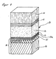
- an example of the plastic composite film (17) has a layer structure comprising a base film (10), adhesive layer (11), metal foil (12), metal protective layer (13) and the functional layer (14), for example comprising a layer of a denatured polyolefin (15 ) and a polyolefin layer (16).
- the base film (10) represents, in particular, the layer facing outward on a battery casing and may be made of oriented polyamide.
- the metal foil (12), such as an aluminum foil, is coated on the inside, to the battery module, facing side, with the 0.1 to 1000 nm thick, applied by a physical deposition method, metal protective layer (13), for example, a chromium layer.
- the metal protective layer (13) provides excellent protection, in particular corrosion protection, for the underlying metal foil (12).
- the functional layer (14) to penetrate,
- the deposited protective protective metal layer (13) reliably retained and do not penetrate to the metal foil (12).
- Such aggressive substances can not unfold their destructive and in particular corrosive action on the metal foil (12) for the metal foil (12).
- the metal foil (12) is a barrier layer against the passage of moisture and gases. By corrosion and pitting the barrier effect is impaired or destroyed. Without barrier effect not only substances from the battery module can come out, it can also substances, such as moisture, penetrate from the outside into the battery module. An impairment of the metal foil (12) also leads to delamination of the plastic composite film. A delamination is to be avoided, since a dissolving in their layers battery casing of the intended effect is no longer able to do justice.
- FIG 2 shows an example of the plastic composite film (17) with the layer structure of the base film (10), adhesive layer (11).
- the functional layer 1 (4) is made up of the layers or layers of plastic (15, 16). Between the layers (15, 16), which is applied by way of example in a thickness of 40 nm, applied by means of a physical deposition method, the metal protective layer (13a), eg a chrome layer, arranged.
- the metal protective layer (13a) can be vapor-deposited either on the plastic layer (15) or the plastic layer (16) or on a case-by-case basis both plastic layers (15, 16). After vapor deposition, the two plastic layers (15, 16) are joined in such a way that the metal protective layer (10a) comes to rest between the two plastic layers (15, 16).
- FIG. 3 shows an example of the plastic composite film (17) with the layer structure of base film (10), adhesive layer (11), metal foil (12), metal protective layer (13) and functional layer (14).
- the functional layer 1 (4) is composed of the layers or layers of plastic (15, 16). Between the layers (15, 16) a second metal protective layer (13a) is arranged.
- the metal protective layer (13a) can be vapor-deposited either on the plastic layer (15) or the plastic layer (16) or on a case-by-case basis both plastic layers (15, 16). After vapor deposition, the two plastic layers (15, 16) are joined such that the metal protective layer (13a) comes to rest between the two plastic layers (15, 16).
- FIG. 4 shows an example of the plastic composite film (17) with the layer structure of base film (10), adhesive layer (11), metal foil (12), metal protective layer (13) and functional layer (14).
- the functional layer 1 (4) is composed of the layers or layers of plastic (15, 16).
- a second metal protective layer (13a) is arranged on the layer (15).
- the second metal protective layer (13a) is vapor-deposited on the plastic layer (15).
- an adhesive layer or an adhesive may be provided between the two metal protective layers (13, 13a).
- a third metal protective layer may be provided between the layers or layers of plastic (15, 16).
- FIG. 5 shows a section through a battery.
- a battery module (19) is inserted in a shell (18) produced by cold forming from the plastic composite film (17) according to the invention.
- the electrodes (20) protrude from the battery module and traverse the edge of the shell (18).
- the cover film (21) can be made, for example, from the same plastic composite film (17) as the shell (18).
- Between the shell (18) and the cover sheet (21) is located along the peripheral shoulder (22) of the shell (18) an endless separation resistant sealing seam (22).
- the battery module is sealed gas and moisture-proof and protected from outside influences.
- plastic composite films according to the invention are listed.
- Base film facing outward metal foil Metal protective layer Functional layer, pointing inwards Case by case used further layer Al thickness in ⁇ m Metal, thickness in nm Case by case used further layer 15 ⁇ m oPA 40 ⁇ m Cr, 40nm 15 ⁇ m oPA 30 ⁇ m PP coex 15 ⁇ m oPA 45 ⁇ m Cr, 40nm 15 ⁇ m oPA 30 ⁇ m PP coex 15 ⁇ m oPA 60 ⁇ m Cr, 40nm 15 ⁇ m oPA 30 ⁇ m PP coex 25 ⁇ m oPA 45 ⁇ m Cr, 40nm 30 ⁇ m PP Coex 25 ⁇ m oPA 60 ⁇ m Cr, 40nm 30 ⁇ m PP Coex 25 ⁇ m oPA 60 ⁇ m Cr, 40nm 30 ⁇ m PP Coex 20 ⁇ m oPA 45 ⁇ m Cr, 40nm 30 ⁇ m PP Coex 25 ⁇ m oPA 100 ⁇
Landscapes
- Chemical & Material Sciences (AREA)
- Chemical Kinetics & Catalysis (AREA)
- Electrochemistry (AREA)
- General Chemical & Material Sciences (AREA)
- Laminated Bodies (AREA)
- Sealing Battery Cases Or Jackets (AREA)
- Physical Vapour Deposition (AREA)
Abstract
a) eine Basisfolie aus Kunststoff
b) eine Metallfolie und
c) eine funktionelle Kunststoffschicht
wobei auf der Schicht b), der Metallfolie, zumindest gegen die Schicht c) gerichtet, und/oder auf der Schicht c), der funktionellen Kunststoffschicht, gegen die Schicht b), die Metallfolie, gerichtet, und/oder in der funktionellen Kunststoffschicht, wenigstens eine durch ein physikalisches Abscheidungsverfahren, wie Vakuum-Bedampfungsverfahren oder Sputtern, aufgebrachte Metallschutzschicht, beispielsweise eine Chromschicht, in einer Dicke von 0,1 bis 1000 nm (Nanometer) angeordnet ist.
Description
- Vorliegende Erfindung betrifft Kunststoffverbundfolien enthaltend, übereinander liegend angeordnet, die Schichten:
- a) eine Basisfolie aus Kunststoff
- b) eine Metallfolie und
- c) eine funktionelle Kunststoffschicht.
- Batteriemodule, d.h. der elektrische Energie erzeugende Teil von Batterien und Akkumulatoren (Primär- und Sekundärelemente) weisen in der Regel ein Gehäuse oder eine Ummantelung auf. Beispielsweise Batteriemodule von Lithium-lonen-Polymer-Batterien oder Lithium-Polymer-Batterien, sind im wesentlichen aus einem positiven und einem negativen Anschluss und einer dazwischen liegenden elektrolytischen Gelschicht aufgebaut. Zum bestimmungsgemässen Gebrauch werden die Batteriemodule ummantelt. Die Ummantelung kann eine Tasche oder eine vorgeformte Packung aus einem mehrschichtigem Laminat aus Kunststoffen sein. Da der Elektrolyt in Gelform aggressive Salze und Lösemittel enthält und mit Restfeuchtigkeit reaktive Gase bilden kann, besteht die Gefahr, dass die aggressiven Substanzen die Ummantelung und in der Folge das Gerät, in dem die Batterie eingebaut ist, beschädigen oder zerstören. Zur Erhöhung der Haltbarkeit einer Batterie kann das Laminat eine Barriereschicht, aus z.B. Aluminiumfolie, enthalten. Die aggressiven Substanzen vermögen die Aluminiumfolie durch Korrosion oder Lochfrass zu schwächen oder zu zerstören oder die einzelnen Schichten die das Laminat der Ummantelung bilden, können sich gegenseitig voneinander lösen, d.h. delaminieren. Sinngemäss gilt der beschriebene chemische Angriff auf die Ummantelung auch für auf anderen chemischen Reaktionen beruhenden Primär- und Sekundärelemente.
- Aus der
US 6,761,994 ist bekannt, die Batteriemodule von Lithium-lon-Polymer Batterien oder Lithium-Polymer-Batterien mit Kunststoffverbundfolien zu umhüllen. Die Kunststoffverbundfolien können aus einer Basisschicht aus Kunststoff, Klebstoff, einer Aluminiumfolie und einer Siegelschicht aufgebaut sein. Um die Widerstandsfähigkeit der Aluminiumfolie gegen Korrosion zu verbessern, wird auf der Oberfläche der Aluminiumfolie chemisch eine Konversionsschicht durch eine Phosphat-Chromat Behandlung erzeugt. - Aus der
EP 1 160 892 ist eine Batteriemodulverpackung bekannt, enthaltend eine Basisschicht, eine Aluminiumschicht, eine chemisch, mittels eines Phenolharzes, dreiwertigem Chromphosphat und Phosphorsäure, erzeugte Konversionsschicht und eine innerste Schicht aus Polypropylenharz. - Die
japanische Patentanmeldung 2002-075298 - Die Erzeugung der Konversionsschichten auf nasschemischem Wege bedarf ätzender und hochtoxischer Substanzen die fallweise auch noch in Lösemitteln aufgenommen sind. Die Erzeugung von nasschemisch abgeschiedenen Chromschichten, besonders bei den verwendeten dünnen Aluminiumfolien, ist nicht nur äusserst aufwendig, sondern es fallen zum Schluss toxische Stoffmischungen an, die aufwendig entsorgt werden müssen.
- Aufgabe vorliegender Erfindung ist es, die genannten Nachteile zu vermeiden und eine zur Ummantelung von Batteriemodulen besonders geeignete Kunststoffverbundfolie, ein Verfahren zu deren Herstellung und die Verwendung der Kunststoffverbundfolie vorzuschlagen.
- Erfindungsgemäss wird dies dadurch erreicht, dass auf der Schicht b), der Metallfolie, zumindest gegen die Schicht c) gerichtet, und/oder auf der Schicht c), der funktionellen Kunststoffschicht, gegen die Schicht b), die Metallfolie gerichtet, und/oder in der funktionellen Kunststoffschicht, wenigstens eine durch ein physikalisches Abscheidungsverfahren aufgebrachte Metallschutzschicht in einer Dicke von 0,1 bis 1000 nm (Nanometer) angeordnet ist.
- Als Metallfolien können Eisen- und Nichteisenmetallfolien, wie Folien aus Eisen, Stahl, Nickel, Kupfer usw. angewendet werden. Die Metallfolien weisen eine Dicke von 12 bis 200 µm, zweckmässig 20 bis 200 µm, bevorzugt 25 bis 75 µm und insbesondere 40 bis 50 µm auf. Bevorzugt sind Folien aus Aluminium und dessen Legierungen, wobei weiches Aluminium zu bevorzugen ist. Beispiele von Folien aus Aluminium oder Aluminiumlegierungen sind solche aus Al 99,0, Al 99-5 oder Legierungen der Typen AA 1xxx und AA 8xxx, wobei die Werkstoffe AA 8006, AA 8014 und AA 8021 besonders geeignet sind. Die Folien aus Aluminium oder Aluminiumlegierungen können die vorstehend angegebenen Dicken aufweisen. Typische Dicken von Aluminiumfolien sind 40, 45, 50, 60 und 100 µm.
- Die Basisfolie aus Kunststoff kann eine oder mehrere Schichten enthalten. Beispielsweise kann es sich um eine Polyesterfolie, z.B. eine Polyethylenterephtalatfolie (PET), eine Polyamidfolie, z.B. eine orientierte Polyamidfolie (oPA), eine Polyolefinfolie, z.B. eine orientierte Polypropylenfolie (oPP) oder eine Folie oder Schicht enthaltend ein säuredenaturiertes Polyolefin sein. Enthält die Basisfolie mehrere Schichten, so kann es sich um zwei oder mehrere jeweils gegenseitig klebstoffkaschierte, extrusionskaschierte und/oder heisskalandrierte Schichten, resp. Folien handeln, Klebstoffkaschierte Schichten oder Folien können mit wässrigen, lösemittelhaltigen und/oder lösemittelfreien Klebstoffen verarbeitet werden. Die Dicke der Basisfolie kann von 12 bis 50 µm, zweckmässig von 15 bis 25 µm, betragen. Typische Dicken solcher Folien sind 12, 15, 20, 23 und 25 µm. Bei der Verwendung der erfindungsgemässen Kunststoffverbundfolien als Ummantelung von Batteriemodulen stellt die Basisfolie die Aussenseite der Ummantelung dar, d.h. ist nach aussen gerichtet.
- Die Basisfolie liegt der Metallfolie an. Zur Erzielung der geforderten Haftung der Basisfolie an der Metallfolie, kann zwischen der Basisfolie und der Metallfolie eine Klebstoffschicht angeordnet sein. Die Klebstoffe können lösemittelfrei, lösemittelbasierend oder auf wässriger Grundlage sein. In anderer Ausführungsform, um eine ausreichende Haftwirkung zwischen den zu verbindenden Schichten oder Folien zu erreichen, kann die Basisfolie säuredenaturierte Polyolefine enthalten oder zwischen der Basisfolie und der Metallfolie kann eine Schicht eines säuredenaturierten Polyolefins angeordnet sein. Die Basisfolie kann auch durch Curtain Coating, Extrusionskaschierung, und/oder durch Heisskalandrierung mit der Metallfolie verbunden werden. Fallweise kann bei den genannten Verfahren ein Primer eingesetzt werden. Zur Verbesserung der Haftung kann eine Plasma- oder Coronavorbehandlung oder eine chemische Vorbehandlung einer oder beider der jeweiligen gegenseitig zu verbindenden Oberflächen vorgesehen sein.
- Die funktionelle Kunststoffschicht kann aus eine Schicht oder mehreren Schichten aufgebaut sein. Ist die funktionelle Kunststoffschicht aus mehreren Schichten aufgebaut, so kann es sich um zwei oder mehrere jeweils gegenseitig klebstoffkaschierte, extrusionskaschierte, heisskalandrierte und/oder durch Curtain Coating erhaltene Schichten, resp. Folien handeln. Bevorzugt sind zwei oder mehrere coextrudierte Schichten. Die funktionelle Schicht enthält beispielsweise Polyamide, wie orientiertes Polyamid (oPA), Polyolefine, wie Polypropylen, orientiertes Polypropylen (oPP) oder Polyethylen, Polyester, wie Polyethylenterephtalat (PET), säuredenaturierte Polyolefine, wie säuredenaturiertes Polypropylen -ethylen, metallocenhaltige Polyolefine, wie metallocenhaltiges Polypropylen oder -ethylen, methacrylsäurehaltige Polyolefine, wie methacrylsäurehaltiges Polypropylen oder - ethylen. Bei den Polypropylenen kann es sich auch um einen Blend von Polypropylen mit Polyethylen oder anderen Polyolefinen handeln. Auch angewendet werden können Copolymere aus Propylen und Ethylen oder anderen Olefinen oder cycloolefinische Copolymere (CoC), cycloolefinische Polymere (COP) oder Polymere und Copolymere des Acrylnitrils, wie Acrylnitril/Methylacrylat-Copolymere (BAREX®). Bevorzugt ist eine funktionelle Schicht, die eine Coextrusionsschicht aus wenigstens zwei Schichten, nämlich einer Polypropylenschicht und/oder einer metallocenhaltigen Polypropylenschicht, und eine methacrylsäurehaltige Polypropylenschicht enthält. Die Gesamtdicke der funktionellen Schicht kann beispielsweise von 12 bis 100 µm betragen, wobei einzelne Schichten von 15 bis 60 µm und zwei oder mehrere Schichten zusammen 40 bis 100 µm Dicke aufweisen können.
- Bei der Verwendung der erfindungsgemässen Kunststoffverbundfolien als Ummantelung von Batteriemodulen stellt die funktionelle Kunststoffschicht die Innenseite der Ummantelung dar, d.h. sie ist nach innen, zum Batteriemodul hin gerichtet.
- Typische Beispiele von funktionellen Schichten ist eine Schicht aus coextrudiertem Polypropylen in einer Dicke von 30 bis 50 µm oder eine Schicht aus coextrudiertem Polyethylen in einer Dicke von 30 µm.
- Ist die funktionelle Kunststoffschicht beispielsweise aus zwei Schichten aufgebaut, so ist eine Schicht gegen die Metallfolie gerichtet, während die andere Schicht entsprechend gegen die Innenseite oder das Batteriemodul gerichtet ist.
- Typische Beispiele von derartigen Schichten sind - zur Metallfolie gewandt - aus einer Schicht aus 15 µm orientiertem Polyamid und - zur Innenseite gewandt - 30 bis 50 µm coextrudiertes Polypropylen oder - zur Metallfolie gewandt - aus einer Schicht aus 12 µm Polyethylenterephtalat und - zur Innenseite gewandt - 50 µm coextrudiertem Polypropylen oder- zur Metallfolie gewandt - aus einer Schicht aus 15 µm orientiertem Polyamid und -zur Innenseite gewandt - 30 µm coextrudiertem Polyethylen oder - zur Metallfolie gewandt - aus einer Schicht aus 20 µm orientiertem Polypropylen und - zur Innenseite gewandt - 30 bis 50 µm coextrudiertem Polypropylen.
- Sinngemäss können auch funktionelle Schichten mit drei oder mehr Einzelschichten angewendet werden.
- Die funktionelle Schicht weist vorteilhaft Siegeleigenschaften auf, d.h. die funktionelle Schicht ist siegelbar, wie kalt- oder heisssiegelbar. Die funktionelle Schicht ist zweckmässig gegen Flächen anderer Verpackungsteile und gegen sich selbst siegelbar. Ist die funktionelle Schicht eine Kombination aus mehreren Einzelschichten, so weist insbesondere die äusserste freiliegende Schicht Siegeleigenschaften auf oder ist siegelbar, resp. die äusserste freiliegende Schicht ist vorteilhaft schweissbar oder kann mittels eines Klebstoffes geklebt werden.
- Die Basisfolie liegt auf der einen Seite der Metallfolie an. Der anderen Seite der Metallfolie liegt die funktionelle Schicht an. Zur Erzielung der geforderten Haftung zwischen funktioneller Schicht und Metallfolie, kann dazwischen eine Klebstoffschicht angeordnet sein. Die Klebstoffe können lösemittelfrei, lösemittelbasierend oder auf wässriger Grundlage sein. In anderer Ausführungsform, um eine ausreichende Haftwirkung zwischen den zu verbindenden Schichten oder Folien zu erreichen, kann die funktionelle Schicht säuredenaturierte Polyolefine enthalten oder zwischen der funktionellen Schicht und der Metallfolie kann eine Schicht eines säuredenaturierten Polyolefins angeordnet sein. Die funktionelle Schicht kann auch durch Extrusionskaschierung, Extrusionsbeschichtung und/oder durch Heisskalandrierung mit der Metallfolie verbunden werden. Fallweise kann bei den genannten Verfahren ein Primer eingesetzt werden. Zur Verbesserung der Haftung kann eine Plasma- oder Coronavorbehandlung einer oder beider der jeweiligen gegenseitig zu verbindenden Oberflächen vorgesehen sein.
- Die erfindungsgemässe Kunststoffverbundfolie enthält eine Metallschutzschicht. Es ist die Aufgabe der Metallschutzschicht die Metallfolie vor aggressiven Stoffen zu schützen. In einer Ausführungsform gemäss vorliegender Erfindung befindet sich auf der Metallfolie, wie auf einer Folie aus Aluminium oder aus einer Aluminiumlegierung, eine 0,1 bis 1000 nm (Nanometer) dicke Metallschutzschicht. In altemativer Ausführungsform liegt die Metallschutzschicht nicht der Metallfolie an, sondern liegt der funktionellen Schicht an. Beim Verbinden der Metallfolie und der funktionellen Schicht kommt die Metalischutzschicht - fallweise über einen Klebstoff oder Haftvermittler - auf die eine Metallfolienoberfläche zu liegen. Die Metallschutzschicht kann auch auf einer Schicht oder Folie eines der genannten Kunststoffe, die mit anderen Schichten oder Folien aus den genannten Kunststoffen zu einer mehrlagigen oder mehrschichtigen funktionellen Schicht verarbeitet werden, abgeschieden werden. Die Metallschutzschicht ist dann zwischen zwei Kunststoffschichten der funktionellen Schicht enthalten.
- Mehrere Metallschutzschichten können vorgesehen sein. Eine erste Metallschutzschicht kann auf der Metallfolie angeordnet sein und eine zweite Metallschutzschicht kann auf der funktionellen Schicht angeordnet sein, wobei in der erfindungsgemässen Kunststoffverbundfolie die Metallschutzschichten einander - fallweise über einen Klebstoff oder Haftvermittler- anliegen.
- In weiterer Ausführungsform ist eine Metallschutzschicht auf der Metallfolie angeordnet und eine Metallschutzschicht ist zwischen zwei Lagen oder Schichten aus Kunststoff innerhalb der funktionellen Schicht angeordnet.
- In wieder anderer Ausführungsform ist eine erste Metallschutzschicht auf einer Aussenseite der funktionellen Schicht und eine zweite Metallschutzschicht zwischen zwei Lagen oder Schichten aus Kunststoff innerhalb der funktionellen Schicht angeordnet. Die funktionelle Schicht ist über die aussen liegende erste Metallschutzschicht - fallweise über einen Klebstoff oder Haftvermittler - mit der Metallfolie verbunden.
- In zusätzlicher Ausführungsform kann eine erste Metallschutzschicht auf der Metallfolie angeordnet sein, eine zweite Metallschutzschicht kann auf der funktionellen Schicht angeordnet sein, wobei in der Kunststoffverbundfolie die Metallschutzschichten - fallweise über einen Klebstoff oder Haftvermittler - einander anliegen und eine dritte Metallschutrschicht ist zwischen zwei Lagen oder Schichten aus Kunststoff in der funktionellen Schicht angeordnet.
- Jede der genannten Metallschutzschichten ist durch ein physikalisches Abscheideverfahren aufgebracht. Beispiele von physikalischen Abscheideverfahren sind Vakuum-Bedampfungsverfahren und Sputtern.
- Zur Beschichtung mit der Metallschutzschicht wird die Metallfolie oder eine Kunststofffolie oder ein Metall-Kunststofffolienverbund in einer Vakuumkammer im Vakuum, als Einzelblätter und besonders zweckmässig von einem Wickel, einer Rolle oder einem Coil abgewickelt, einer Atmosphäre aus im wesentlichen verdampften oder gesputtertem Metall ausgesetzt. Der metallhaltige Dampf schlägt sich in einer 0,1 bis 1000 nm dicken Schicht auf wenigstens einer Seite der Metallfolie nieder. Kontinuierlich kann die mit der Metallschutzschicht bedampfte Metallfolie wieder auf einen gegenüberliegenden Wickel, Rolle oder Coil aufgehaspelt werden. Die Metallschutzschicht kann beispielsweise aus Cu, Au, Ag, Ni, Pd, Pt, Ti, Zr, Hf, V, Cr, Mo, W, Zn, Cd, Hg, Si, Ge, Sn, Pb, Fe, Ru, Os, Mn, Tc, Re, Ga, In, TI, Bi oder aus Gemischen davon sein. Bevorzugt sind Cr, Ti und Zr, allein oder in einem Gemisch zweier oder allen drei der Metalle und vor allem bevorzugt ist Cr. Entsprechend der geforderten Metallschutzschicht werden die Ausgangsmaterialien aus Substanzen, enthaltend das oder die oder bestehend aus dem oder den vorstehend genannten Elementen, ausgewählt. Beispielsweise wird das Metall in einer Vakuumkammer vorgelegt und mittels Elektronenstrahlkanone die auf das Targetmaterial gerichtet ist, verdampft oder mittels einer Sputterkathode gesputtert. Das Targetmaterial ist beispielsweise eine Platte aus dem zu verdampfenden Metall. Soll eine Mischung von Metallen abgeschieden werden, so kann ein Gemisch der entsprechenden Metalle oder mehreren Metallplatten aus den entsprechenden Metallen verdampft oder gesputtert werden. Das verdampfte oder gesputterte Metall schlägt sich auf der Oberfläche der Metallfolie in der angegebenen Dicke nieder. Die Dicke der Metallabscheidung lässt sich u.a. über die Durchlaufgeschwindigkeit der Metallfolie und durch die Stärke des Elektronenstrahls, resp. die Leistung der Sputterkathode, steuern.
- Als besonders zweckmässig erweist sich eine Plasma-Vorbehandlung mit beispielsweise Argon (Ar), Stickstoff (N2), NH3, NOx (Stickoxyde) und bevorzugt mittels Sauerstoffplasma, der Metallfolie oder der Kunststofffolien oder -schichten in der Vakuumanlage. Die Vorbehandlung kann direkt in der Vakuumanlage vor dem Beschichten erfolgen. Die Plasmavorbehandlung für zu besonders guter Schichthaftung der Metallfolie, der Metallschutzschicht und der Kunststofffolien oder -schichten untereinander. Bevorzugt wird die Metallschutzschicht mittels Elektronenstrahlverdampfung und mit Chrom als Targetmaterial erzeugt. Besonders bevorzugt wird eine Plasmavorbehandlung mittels Sauerstoffplasma und eine Verdampfung mittels Elektronenstrahlverdampfung mit Chrom als Targetmaterial.
- Ein Beispiel eines Verfahrens zum Aufbringen der Metallschutzschicht bei der Herstellung einer erfindungsgemässen Kunststoffverbundfolie ist, dass das Aufbringen der Metallschutzschicht durch ein Chromabscheideverfahren ausgeführt wird. Die Basisfolie, verbunden mit der Aluminiumfolie, oder die funktionelle Schicht, kann in einer Vakuumkammer einer Plasmabehandlung in einem Sauerstoffplasma und danach einer durch Elektronenstrahlverdampfen erzeugten chromhaltigen Dampfwolke ausgesetzt werden, wobei sich das Chrom auf der freien Oberfläche der Folie oder Schicht niederschlägt. Das Chromabscheideverfahren kann derart ausgeführt werden, dass eine Kunststoff-Aluminium-Folie, z.B. aus orientiertem Polyethylen oder Polyester und einer Aluminiumfolie, in einer Vakuumkammer einer Plasmabehandlung in einem Sauerstoffplasma und danach einer chromhaltigen Dampfwolke ausgesetzt wird. Die Dampfwolke wird aus einem Chromgranulat, welches mit einer Elektronenstrahlkanone bei ca. 30 bis 40 kV mit einem Strahlstrom von beispielsweise 1,1 bis 1,5 A erhitzt und verdampft wird, erzeugt. Bei einer Durchlaufgeschwindigkeit der Kunststoff-Aluminium-Folie oder der funktionellen Schicht von beispielsweise 120 m/min kann eine Chromschicht in einer Dicke von rund 80 nm erzeugt werden.
- Im Falle, dass die Metallfolie über eine Beschichtungswalze, die in der Vakuumkammer angeordnet ist, geführt wird, schlägt sich der Metalldampf auf nur der freien, nicht die Beschichtungswalze berührende, Seite der Metallfolie nieder. Wird die Metallfolie frei, im sog. "free-span", d.h. beidseitig dem verdampften Metall ausgesetzt, durch die Vakuumkammer geführt, werden beide Seiten der Metallfolie beschichtet. Um die Beschichtungsgeschwindigkeit hoch zu halten und den Energieeintrag und den Verbrauch an Targetmaterialien zu minimieren, wird zweckmässig nur eine Seite der Metallfolie beschichtet.
- Es ist auch möglich, die bereits mit der Basisfolie beschichtete Metallfolie in der Vakuumkammer dem verdampften Metall auszusetzen und somit die Metallfolie auf der freien Seite mit der Metallschutzschicht zu belegen.
- Somit betrifft vorliegende Erfindung auch ein Verfahren zur Herstellung einer Kunststoffverbundfolie zur Verwendung als Batterieummantelung. Gemäss dem erfindungsgemässen Verfahren kann auf wenigstens einer der beiden Oberflächen der Metallfolie eine Metallschutzschicht aufgebracht werden. In anderer Weise kann die Metallschutzschicht an der Oberfläche der funktionellen Schicht, die an der Kunststoffverbundfolie zur Metallfolie weist, angeordnet sein. Auch kann die Metallschutzschicht zwischen zwei Schichten oder Folien der funktionellen Schicht angeordnet sein. Es kann auch eine erste Metallschutzschicht auf der funktionellen Schicht - an der zur Metallfolie weisenden Oberfläche - und eine zweite Metallschutzschicht zwischen zwei Schichten oder Folien der funktionellen Schicht angeordnet sein. Das Aufbringen der Metallschutzschicht erfolgt durch ein physikalisches Abscheidungsverfahren in einer Dicke von 0,1 bis 1000 nm (Nanometer).
- Bevorzugt wird auf wenigstens einer Oberflächen der Metallfolie die Metallschutzschicht durch ein Vakuum-Bedampfungsverfahren oder durch Sputtern abgeschieden.
- Die Metallschutzschicht kann in einer Dicke von 2 bis 100 nm, vorzugsweise von 5 bis 50 nm, insbesondere 40 nm, abgeschieden werden.
- Mit dem erfindungsgemässen Verfahren wird als Metallschutzschicht zweckmässig Zirkon oder Titan und vorzugsweise Chrom abgeschieden.
- Die mit der Metallschutzschicht belegte Metallfolie, vorzugsweise mit einer Chromschicht belegte Aluminiumfolie, ist auf der einen Seite mit der Basisfolie, zweckmässig mittels einer Adhäsivschicht, wie eines Klebstoffes, eines Kaschierklebers, eines Siegellackes oder -folie und/oder eines Primers verbunden. Auf der anderen Seite der Metallfolie, befindet sich die aufgedampfte Metallschutzschicht und mit der Metallschutzschicht, ist die funktionelle Kunststoffschicht, fallweise über eine Adhäsivschicht, wie einen Klebstoff, einen Kaschierkleber, einen Siegellack oder - folie und/oder einen Primer verbunden.
- Demnach sind besonders bevorzugte Kunststoffverbundfolien nach vorliegender Erfindung solche, deren Basisfolie aus Kunststoff eine 15 bis 25 µm dicke orientierte Polyamidschicht, eine 12 bis 23 µm dicke Polyethylenterephtalatschicht oder eine Schicht aus zwei Lagen aus orientiertem Polyamid in einer Dicke von jeweils 15 bis 25 µm ist, die Metallfolie aus Aluminium in einer Dicke von 45 bis 60 µm ist, die Metallschutzschicht aus Chrom ist und eine Dicke von ca. 40 nm aufweist und die funktionelle Kunststoffschicht aus einer Schicht aus 15 µm orientiertem Polyamid und 30 bis 50 µm coextrudiertem Polypropylen oder aus einer Schicht aus 12 µm Polyethylenterephtalat und 50 µm coextrudiertem Polypropylen oder aus einer Schicht aus 15 µm orientiertem Polyamid und 30 µm coextrudiertem Polyethylen oder aus einer Schicht aus 20 µm orientiertem Polypropylen und 30 bis 50 µm coextrudiertem Polypropylen ist.
- Die erfindungsgemässe Kunststoffverbundfolie wird als Batterieummantelung für Batteriemodule von Batterien und Akkumulatoren, wie Primär- und Sekundärbatterien, vorzugsweise Lithium-lonen-Polymer Batterien und Lithium-Polymer-Batterien, verwendet,
- Beispielsweise kann die Kunststoffverbundfolie zu einer Tasche geformt, das Batteriemodul in die Tasche eingelegt und die Tasche an ihrem offenen Ende versiegelt, verschweisst oder verklebt werden. Das Batteriemodule kann auch ein einen entsprechenden Zuschnitt der Kunststoffverbundfolie eingeschlagen, eingewickelt oder eingerollt und die Kanten der Kunststoffverbundfolie können gegenseitig versiegelt, verschweisst oder verklebt werden.
- In wieder anderer Weise kann aus der Kunststoffverbundfolie, beispielsweise durch heiss- und bevorzugt durch kaltverformen, ein Formkörper hergestellt werden. Das Verformen kann durch Tiefziehen, Streckziehen oder durch eine Kombination beider Verfahren erfolgen. Solche Formkörper können Schalen, Halbschalen oder etuiförmige Behälter sein. Das Batteriemodule wird in die Schale eingelegt und die Schale kann mit einer Deckfolie verschlossen werden. Die Deckfolie ist insbesondere ein passender Abschnitt der erfindungsgemässen Kunststoffverbundfolie. Das Verschliessen kann durch Siegelnähte entlang des Schalenrandes erfolgen. Es kann auch das Batteriemodul in eine untere Halbschale eingelegt und die untere Halbschale mit einer oberen Halbschale überdeckt werden. Die beiden Halbschalen werden entlang ihrer sich berührender Ränder gesiegelt und damit trennfest verbunden. Es ist auch möglich, das Batteriemodul in einen etwa etuiförmigen Behälter einzuführen und die Einführöffnung durch verformen des Behälters oder durch überdecken der Öffnung mit einem Deckel oder einer Kunststoffverbundfolie zu verschliessen. In allen Fällen müssen die aus dem Batteriemodul führenden Elektroden durch die Batterieumhüllungen geführt werden. Zweckmässig werden die Elektroden durch die jeweilige Einfüllöffnung für das Batteriemodul geführt. Die Elektroden können durch die Einfüllöffnung der Tasche, zwischen Schale und Bedeckelung, durch die Naht zwischen den beiden Halbschalen oder durch die Naht zwischen Behälter und Deckel geführt werden. Die Siegelnähte an den Taschen, Schalen, Halbschalen und Behältern sind vorteilhaft zumindest flüssigkeitsdicht, vorzugsweise luft- oder gasdicht, und trennfest. Die Ausleitung der Elektroden soll ebenfalls dicht verschlossen werden, so dass entlang der Elektroden keine Stoffe aus- oder eintreten können. Wahlweise kann statt einer Versiegelung auch eine Verschweissung oder eine Verklebung angewendet werden.
- Bevorzugt sind Batterieummantelungen unter Verwendung einer kaltverformten Kunststoffverbundfolie. Bevorzugt werden die Kunststoffverbundfolien zu Schalen kaltverformt. Unter "kaltverformt" wird eine Formgebung, beispielhaft durch Tiefen, wie Tief- oder Streckziehen, bei Raumtemperatur, etwa 20°C bis 30°C. und fallweise bis zu Temperaturen von etwa 50°C 70°C, verstanden. Das Batteriemodul kann in die Schale eingelegt, die Elektroden über den Schalenrand geführt und die Schale dicht und trennfest mit einer Deckelfolie, aus zweckmässig der erfindungsgemässen Kunststoffverbundfolie versiegelt werden oder die Schale kann mittels einem aufgesiegelten Deckelformteil, aus zweckmässig einem getieften Formteil aus der erfindungsgemässen Kunststoffverbundfolie, dicht und trennfest verschlossen werden.
- Figuren 1 bis 5 erläutern vorliegende Erfindung beispielhaft näher.
- Figuren 1 bis 4 zeigen schematisch die Schichtfolge von erfindungsgemässen Kunststoffverbundfolien.
- Figur 5 stellt einen Schnitt durch eine Batterie unter Verwendung einer erfindungsgemässen Batterieummantelung dar.
- Gemäss Figur 1 weist ein Beispiel der Kunststoffverbundfolie (17) einen Schichtaufbau aus Basisfolie (10), Adhäsivschicht (11), Metallfolie (12), Metallschutzschicht (13) und der funktionellen Schicht (14), beispielhaft aus einer Lage eines denaturierten Polyolefins (15) und einer Polyolefinschicht (16) auf. Die Basisfolie (10) stellt insbesondere die an einer Batterieummantelung nach aussen weisende Schicht dar und kann aus orientiertem Polyamid sein. Die Metallfolie (12), wie eine Aluminiumfolie, ist auf der nach innen, zum Batteriemodul, weisenden Seite, mit der 0,1 bis 1000 nm dicken, mittels eines physikalischen Abscheidungsverfahrens aufgebrachten, Metallschutzschicht (13), z.B. einer Chromschicht, beschichtet. Die Metallschutzschicht (13) stellt einen hervorragenden Schutz, insbesondere Korrosionsschutz, für die darunter liegende Metallfolie (12) dar. Für die Metallfolie (12) schädliche, z.B. korrosive, aus dem Batteriemodul austretende Stoffe vermögen fallweise die funktionelle Schicht (14) zu durchdringen, werden jedoch durch die aufgedampfte schützende Metallschutzschicht (13) zuverlässig zurückgehalten und dringen nicht bis zur Metallfolie (12) vor. Somit können solche aggressiven Stoffe ihre für die Metallfolie (12) zerstörerische und insbesondere korrosive Wirkung an der Metallfolie (12) nicht entfalten. Die Metallfolie (12) stellt eine Barriereschicht gegen den Durchtritt von Feuchtigkeit und Gasen dar. Durch Korrosion und Lochfrass wird die Barrierewirkung beeinträchtigt oder zerstört. Ohne Barrierewirkung können nicht nur Stoffe aus dem Batteriemodul nach aussen treten, es können auch Stoffe, wie Feuchtigkeit, von aussen in das Batteriemodul eindringen. Eine Beeinträchtigung der Metallfolie (12) führt auch zur Delamination der Kunststoffverbundfolie. Eine Delamination ist zu vermeiden, da eine sich in ihre Schichten auflösende Batterieummantelung der zugedachten Wirkung nicht mehr gerecht zu werden vermag.
- Figur 2 zeigt ein Beispiel der Kunststoffverbundfolie (17) mit dem Schichtaufbau aus Basisfolie (10), Adhäsivschicht (11). Metallfolie (12) und funktioneller Schicht (14). Die funktionelle Schicht 1 (4) ist aus den Schichten oder Lagen aus Kunststoff (15, 16) aufgebaut, Zwischen den Schichten (15, 16) ist die beispielhaft in 40 nm Dicke, mittels eines physikalischen Abscheidungsverfahrens aufgebracht, die Metallschutzschicht (13a), z.B. eine Chromschicht, angeordnet. Die Metallschutzschicht (13a) kann entweder auf die Kunststoffschicht (15) oder die Kunststoffschicht (16) oder fallweise beide Kunststoffschichten (15, 16) aufgedampft werden. Nach dem Aufdampfen werden die beiden Kunststoffschichten (15, 16) derart gefügt, dass die Metallschutzschicht (10a) zwischen die beiden Kunststoffschichten (15, 16) zu liegen kommt.
- Figur 3 zeigt ein Beispiel der Kunststoffverbundfolie (17) mit dem Schichtaufbau aus Basisfolie (10), Adhäsivschicht (11), Metallfolie (12), Metallschutzschicht (13) und funktioneller Schicht (14). Die funktionelle Schicht 1 (4) ist aus den Schichten oder Lagen aus Kunststoff (15, 16) aufgebaut. Zwischen den Schichten (15, 16) ist eine zweite Metallschutzschicht (13a) angeordnet. Die Metallschutzschicht (13a) kann entweder auf die Kunststoffschicht (15) oder die Kunststoffschicht (16) oder fallweise beide Kunststoffschichten (15, 16) aufgedampft werden. Nach dem Aufdampfen werden die beiden Kunststoffschichten (15, 16) derart gefügt, dass die Metallschutzschicht (13a) zwischen die beiden Kunststoffschichten (15, 16) zu liegen kommt.
- Figur 4 zeigt ein Beispiel der Kunststoffverbundfolie (17) mit dem Schichtaufbau aus Basisfolie (10), Adhäsivschicht (11), Metallfolie (12), Metallschutzschicht (13) und funktioneller Schicht (14). Die funktionelle Schicht 1(4) ist aus den Schichten oder Lagen aus Kunststoff (15, 16) aufgebaut. Auf der Schicht (15) ist eine zweite Metallschutzschicht (13a) angeordnet. Die zweite Metallschutzschicht (13a) ist auf die Kunststoffschicht (15) aufgedampft. Fallweise kann zwischen den beiden Metallschutzschichten (13, 13a) eine Adhäsivschicht oder ein Klebstoff (nicht abgebildet) vorgesehen sein. Der Vollständigkeit halber sei auf eine weitere mögliche Variante des Schichtaufbaues gemäss Figur 4 hingewiesen. Eine dritte Metallschutzschicht kann zwischen den Schichten oder Lagen aus Kunststoff (15, 16) vorgesehen sein.
- Figur 5 stellt einen Schnitt durch eine Batterie dar. In eine aus der erfindungsgemässen Kunststoffverbundfolie (17) durch Kaltverformen hergestellte Schale (18), z.B. rechteckiger Grundfläche, ist ein Batteriemodul (19) eingelegt. Die Elektroden (20) ragen aus dem Batteriemodul und queren den Rand der Schale (18). An den die Schale (18) überragenden Teilen der Elektroden kann beim Gebrauch der Batterie die Energie abgegriffen werden. Die Schale (18) ist mit einer Deckelfolie (21) abgedeckt. Die Deckelfolie (21) kann beispielsweise aus der gleichen Kunststoffverbundfolie (17), wie die Schale (18) gefertigt sein. Zwischen der Schale (18) und der Deckelfolie (21) befindet sich entlang der umlaufenden Schulter (22) der Schale (18) eine endlose trennfeste Siegelnaht (22). Damit ist das Batteriemodul gas- und feuchtigkeitsdicht eingeschlossen und von Ausseneinflüssen geschützt.
- In nachfolgender Tabelle sind Beispiele von erfindungsgemässen Kunststoffverbundfolien gelistet.
Basisfolie, nach aussen weisend Metallfolie Metallschutzschicht Funktionelle Schicht, nach innen weisend Fallweise eingesetzte weitere Schicht Al Dicke in µm Metall, Dicke in nm Fallweise eingesetzte weitere Schicht 15 µm oPA 40 µm Cr, 40nm 15 µm oPA 30 µm PP-Coex 15 µm oPA 45 µm Cr, 40nm 15 µm oPA 30 µm PP-Coex 15 µm oPA 60 µm Cr, 40nm 15 µm oPA 30 µm PP-Coex 25 µm oPA 45 µm Cr, 40nm 30µm PP Coex 25 µm oPA 60 µm Cr, 40nm 30µm PP Coex 25 µm oPA 60 µm Cr, 40nm 30µm PP Coex 20 µm oPA 45 µm Cr, 40nm 30µm PP Coex 25 µm oPA 100 µm Cr, 40nm 30µm PP Coex 15 µm oPA 45µm Cr, 40nm 15 µm oPA 50µm PP-Coex 15 µm oPA 60 µm Cr, 40nm 15 µm oPA 50µm PP-Coex 15 µm oPA 60 µm Cr, 40nm Cr, 40nm, 15 µm oPA 50 µm PP-Coex 25 µm oPA 45 µm Cr, 40nm 50µm PP Coex 25 µm oPA 60 µm Cr, 40nm 50µm PP Coex 25 µm oPA 60 µm Cr, 40nm 50µm PP Coex 20 µm oPA 45 µm Cr, 40nm 50µm PP Coex 25 µm oPA 100 µm Cr, 40nm 50µm PP Coex 12 µm PET 45 µm Cr, 40nm 12 µm PET 50µm PP Coex 12 µm PET 60 µm Cr, 40nm 12 µm PET 50µm PP Coex 23 µm PET 45 µm Cr, 40nm 50µm PP Coex 23 µm PET 60 µm Cr, 40nm 50µm PP Coex 23 µm PET 60 µm Cr, 40nm 50µm PP Coex 12 µm PET 45 µm Cr, 40nm 50µm PP Coex 23 µm PET 100 µm Cr, 40nm 50µm PP Coex 25 µm oPA 45 µm Cr, 40nm 12 µm PAN 50µm PP Coex 25 µm oPA 45 µm Cr, 40nm 12 µm PET 50µm PP Coex 25 µm oPA 60 µm Cr, 40nm 12 µm PET 50µm PP Coex 23 µm PET 45 µm Cr, 40nm 30µm PP Coex 23 µm PET 60 µm Cr, 40nm 30µm PP Coex 23 µm PET 60 µm Cr, 40nm 30µm PP Coex 12 µm PET 45 µm Cr, 40nm 30µm PP Coex 23 µm PET 100 µm Cr, 40nm 30µm PP Coex 15 µm oPA 45 µm Cr, 40nm 15 µm CoC 30 µm PE-Coex 15 µm oPA 45 µm Cr, 40nm 15 µm oPA 30 µm PE-Coex 15 µm oPA 60 µm Cr, 40nm 15 µm oPA 30 µm PE-Coex 25 µm oPA 45 µm Cr, 40nm 30µm PE Coex 25 µm oPA 60 µm Cr, 40nm 30µm PE Coex 25 µm oPA 60 µm Cr, 40nm 30µm PE Coex 20 µm oPA 45 µm Cr, 40nm 30µm PE Coex 25 µm oPA 100 µm Cr, 40nm 30µm PE Coex 25 µm oPA 25 µm oPA 45 µm Cr, 40nm 30µm PP Coex 25 µm oPA 25 µm oPA 100 µm Cr, 40nm 30µm PE Coex 20 µm oPA 20 µm oPA 45 µm Cr, 40nm 30µm PP Coex 20 µm oPA 20 µm oPA 100 µm Cr, 40nm 30µm PE Coex 15 µm oPA 15 µm oPA 45 µm Cr, 40nm 30µm PP Coex 15 µm oPA 15 µm oPA 100 µm Cr, 40nm 30µm PE Coex 20 µm oPP 100 µm Cr, 40nm 30µm PE Coex 25 µm oPA 40 µm Cr, 40nm 20µm oPP 50µm PP Coex 25 µm oPA 45 µm Cr, 40nm 20µm oPP 50µm PP Coex 25 µm oPA 45 µm Cr, 40nm 20µm oPP 30µm PP Coex 15 µm oPA 45 µm Cr, 40nm 20µm oPP 50µm PP Coex 15 µm oPA 45 µm Cr. 40nm 20µm oPP 30µm PP Coex - Die Zahlen zu den Kunststofffolien oder -schichten bedeuten die Dicke in µm.
- oPA:
- orientiertes Polyamid
- PET:
- Polyethylenterephtalat
- oPP:
- orientiertes Polypropylen
- Al:
- Aluminium
- Cr:
- Chrom
- nm:
- Nanometer
- PP:
- Polypropylen
- PE:
- Polyethlen
- PAN:
- Polyacrylnitril
- CoC:
- Cycloolefinisches Copolymer
- Coex:
- Coextrudiert
Claims (12)
- Kunststoffverbundfolie enthaltend, übereinander liegend angeordnet, die Schichtena) eine Basisfolie aus Kunststoffb) eine Metallfolie undc) eine funktionelle Kunststoffschichtdadurch gekennzeichnet, dass
auf der Schicht b), der Metallfolie, zumindest gegen die Schicht c) gerichtet, und/oder auf der Schicht c), der funktionellen Kunststoffschicht, gegen die Schicht b), die Metallfolie, gerichtet, und/oder in der funktionellen Kunststoffschicht, wenigstens eine durch ein physikalisches Abscheidungsverfahren aufgebrachte Metallschutzschicht in einer Dicke von 0,1 bis 1000 nm (Nanometer) angeordnet ist. - Kunststoffverbundfolie nach Anspruch 1, dadurch gekennzeichnet, dass die Metallschutzschicht eine Dicke von 2 bis 100 nm vorzugsweise von 5 bis 50 nm, insbesondere 40 nm aufweist.
- Kunststoffverbundfolie nach Ansprüchen 1 und 2, dadurch gekennzeichnet, dass die Metallschutzschicht durch ein Vakuum-Bedampfungsverfahren oder durch Sputtern erzeugte Metallschutzschicht ist.
- Kunststoffverbundfolie nach Ansprüchen 1 bis 3, dadurch gekennzeichnet, dass die Metallschutzschicht eine Chrom-, eine Titan- oder eine Zirkonschicht, bevorzugt eine Chromschicht ist.
- Kunststoffverbundfolie nach Ansprüchen 1 bis 4, dadurch gekennzeichnet, dass die Basisfolie aus Kunststoff eine 15 bis 25 µm dicke orientierte Polyamidschicht, eine 12 bis 23 µm dicke Polyethylenterephtalatschicht oder eine Schicht aus zwei Lagen aus orientiertem Polyamid in einer Dicke von jeweils 15 bis 25 µm ist, die Metallfolie aus Aluminium in einer Dicke von 45 bis 60 µm ist, die Metallschutzschicht aus Chrom ist und eine Dicke von 40 nm aufweist und die funktionelle Kunststoffschicht aus einer Schicht aus 15 µm orientiertem Polyamid und 30 bis 50 µm coextrudiertem Polypropylen oder aus einer Schicht aus 12 µm Polyethylenterephtalat und 50 µm coextrudiertem Polypropylen oder aus einer Schicht aus 15 µm orientiertem Polyamid und 30 µm coextrudiertem Polyethylen oder aus einer Schicht aus 20 µm orientiertem Polypropylen und 30 bis 50 µm coextrudiertem Polypropylen ist.
- Batterieummantelung für Batteriemodule, vorzugsweise Lithium-lonen-Polymer-Batterien und Lithium-Polymer-Batterien, unter Verwendung einer Kunststoffverbundfolie nach Anspruch 1.
- Batterieummantelung nach Anspruch 6 unter Verwendung einer kaltverformten Kunststoffverbundfolie.
- Verfahren zur Herstellung einer Kunststoffverbundfolie nach Anspruch 1, dadurch gekennzeichnet, dass auf wenigstens einer Oberflächen der Schicht b), der Metallfolie, zumindest gegen die Schicht c) gerichtet, und/oder auf der Schicht c), der funktionellen Kunststoffschicht, gegen die Schicht b), die Metallfolie, gerichtet, und/oder in der funktionellen Kunststoffschicht, wenigstens eine Metallschutzschicht in einer Dicke von 0,1 bis 1000 nm (Nanometer) durch ein physikalisches Abscheidungsverfahren aufgebracht wird.
- Verfahren zur Herstellung einer nach Anspruch 8, dadurch gekennzeichnet, dass auf wenigstens einer Oberflächen der Metallfolie die Metallschutzschicht durch ein Vakuum-Bedampfungsverfahren oder durch Sputtem abgeschieden wird.
- Verfahren zur Herstellung einer Kunststoffverbundfolie nach Ansprüchen 8 und 9, dadurch gekennzeichnet, dass die Metallschutzschicht in einer Dicke von 2 bis 100 nm, vorzugsweise von 5 bis 50 nm und insbesondere 40 nm abgeschieden wird.
- Verfahren zur Herstellung einer Kunststoffverbundfolie nach Ansprüchen 8 bis 10, dadurch gekennzeichnet, dass als Metallschutzschicht Zirkon oder Titan und vorzugsweise Chrom abgeschieden wird.
- Verfahren zur Herstellung einer Kunststoffverbundfolie nach Ansprüchen 8 bis 11, dadurch gekennzeichnet, dass das Aufbringen der Metallschutzschicht durch ein Chromabscheideverfahren ausgeführt wird, wobei die Basisfolie a) verbunden mit der Metallfolie b) oder die funktionelle Schicht c) in einer Vakuumkammer einer Plasmabehandlung in einem Sauerstoffplasma und danach einer durch Elektronenstrahlverdampfen erzeugten chromhaltigen Dampfwolke ausgesetzt wird und sich eine Chromschicht auf der Folie oder Schicht niederschlägt.
Priority Applications (11)
| Application Number | Priority Date | Filing Date | Title |
|---|---|---|---|
| EP06405319A EP1884353A1 (de) | 2006-07-24 | 2006-07-24 | Kunststoffverbundfolie |
| TW096121334A TW200818577A (en) | 2006-07-24 | 2007-06-13 | Plastic laminate film |
| ARP070102967A AR061800A1 (es) | 2006-07-24 | 2007-07-03 | Lamina compuesta de plastico |
| JP2009521135A JP2009544492A (ja) | 2006-07-24 | 2007-07-11 | プラスチックラミネートフィルム |
| US12/374,960 US20090317708A1 (en) | 2006-07-24 | 2007-07-11 | Plastic laminate film |
| KR1020087027855A KR20090035475A (ko) | 2006-07-24 | 2007-07-11 | 플라스틱 적층 막 |
| PCT/EP2007/006131 WO2008011987A2 (de) | 2006-07-24 | 2007-07-11 | Kunststoffverbundfolie |
| AU2007278582A AU2007278582A1 (en) | 2006-07-24 | 2007-07-11 | Plastics composite foil |
| CNA200780028073XA CN101495305A (zh) | 2006-07-24 | 2007-07-11 | 塑料复合膜 |
| PE2007000949A PE20080635A1 (es) | 2006-07-24 | 2007-07-20 | Lamina compuesta de plastico |
| CL200702146A CL2007002146A1 (es) | 2006-07-24 | 2007-07-23 | Lamina compuesta de plastico que contiene una lamina de base de plastico, una lamina de metal y una capa de plastico funcional que comprende una capa protectora de metal colocada mediante un procedimiento de precipitacion; revestimiento de bateria pa |
Applications Claiming Priority (1)
| Application Number | Priority Date | Filing Date | Title |
|---|---|---|---|
| EP06405319A EP1884353A1 (de) | 2006-07-24 | 2006-07-24 | Kunststoffverbundfolie |
Publications (1)
| Publication Number | Publication Date |
|---|---|
| EP1884353A1 true EP1884353A1 (de) | 2008-02-06 |
Family
ID=37561231
Family Applications (1)
| Application Number | Title | Priority Date | Filing Date |
|---|---|---|---|
| EP06405319A Withdrawn EP1884353A1 (de) | 2006-07-24 | 2006-07-24 | Kunststoffverbundfolie |
Country Status (11)
| Country | Link |
|---|---|
| US (1) | US20090317708A1 (de) |
| EP (1) | EP1884353A1 (de) |
| JP (1) | JP2009544492A (de) |
| KR (1) | KR20090035475A (de) |
| CN (1) | CN101495305A (de) |
| AR (1) | AR061800A1 (de) |
| AU (1) | AU2007278582A1 (de) |
| CL (1) | CL2007002146A1 (de) |
| PE (1) | PE20080635A1 (de) |
| TW (1) | TW200818577A (de) |
| WO (1) | WO2008011987A2 (de) |
Cited By (4)
| Publication number | Priority date | Publication date | Assignee | Title |
|---|---|---|---|---|
| WO2011020581A1 (en) * | 2009-08-18 | 2011-02-24 | Basell Polyolefine Gmbh | Housing for electrical power cells in electrically driven automotive vehicles |
| WO2011085944A1 (de) | 2010-01-15 | 2011-07-21 | 3A Technology & Management Ltd. | Batteriepaket |
| DE102017215147A1 (de) | 2017-08-30 | 2019-02-28 | Bayerische Motoren Werke Aktiengesellschaft | Elektrochemische energiespeichervorrichtung und verfahren zur herstellung dieser |
| EP3907073A1 (de) | 2020-05-06 | 2021-11-10 | Amcor Flexibles Kreuzlingen AG | Mehrschichtige struktur für batterieumhüllung |
Families Citing this family (41)
| Publication number | Priority date | Publication date | Assignee | Title |
|---|---|---|---|---|
| JP5598080B2 (ja) * | 2010-05-17 | 2014-10-01 | 大日本印刷株式会社 | ガスバリア性シートの製造方法 |
| CN101992570B (zh) * | 2010-08-26 | 2015-03-25 | 昆山永翔光电科技有限公司 | 锂电池封装铝塑膜 |
| US8989821B2 (en) | 2011-08-31 | 2015-03-24 | Apple Inc. | Battery configurations for electronic devices |
| JP5980495B2 (ja) | 2011-11-07 | 2016-08-31 | 日本パーカライジング株式会社 | 樹脂フィルム付金属製外装材及びその製造方法 |
| US9343716B2 (en) | 2011-12-29 | 2016-05-17 | Apple Inc. | Flexible battery pack |
| JP5948893B2 (ja) * | 2012-01-23 | 2016-07-06 | デクセリアルズ株式会社 | 電池ケース用包材及び非水電解液二次電池 |
| US9812680B2 (en) | 2012-08-30 | 2017-11-07 | Apple Inc. | Low Z-fold battery seal |
| US9136510B2 (en) | 2012-11-26 | 2015-09-15 | Apple Inc. | Sealing and folding battery packs |
| US10211433B2 (en) * | 2012-11-27 | 2019-02-19 | Apple Inc. | Battery packaging |
| US10033029B2 (en) | 2012-11-27 | 2018-07-24 | Apple Inc. | Battery with increased energy density and method of manufacturing the same |
| US9711770B2 (en) | 2012-11-27 | 2017-07-18 | Apple Inc. | Laminar battery system |
| US9899661B2 (en) | 2013-03-13 | 2018-02-20 | Apple Inc. | Method to improve LiCoO2 morphology in thin film batteries |
| US9570775B2 (en) | 2013-03-15 | 2017-02-14 | Apple Inc. | Thin film transfer battery systems |
| US9601751B2 (en) | 2013-03-15 | 2017-03-21 | Apple Inc. | Annealing method for thin film electrodes |
| US9887403B2 (en) | 2013-03-15 | 2018-02-06 | Apple Inc. | Thin film encapsulation battery systems |
| US10141600B2 (en) | 2013-03-15 | 2018-11-27 | Apple Inc. | Thin film pattern layer battery systems |
| CN104716276B (zh) * | 2013-12-13 | 2017-12-26 | 中国科学院大连化学物理研究所 | 一种金属/空气电池阳极保护结构 |
| US9593969B2 (en) | 2013-12-27 | 2017-03-14 | Apple Inc. | Concealed electrical connectors |
| US9479007B1 (en) | 2014-02-21 | 2016-10-25 | Apple Inc. | Induction charging system |
| CN103811703B (zh) * | 2014-02-26 | 2015-11-25 | 江苏安博瑞新材料有限公司 | 一种锂电池用铝塑复合膜及制备方法、锂电池 |
| CN103811685B (zh) * | 2014-02-26 | 2016-03-30 | 江苏华盈新材料有限公司 | 一种锂离子电池软包装用铝塑复合膜及锂离子电池 |
| US20150255776A1 (en) | 2014-03-06 | 2015-09-10 | Apple Inc. | Battery Pack System |
| US9455582B2 (en) | 2014-03-07 | 2016-09-27 | Apple Inc. | Electronic device and charging device for electronic device |
| US9917335B2 (en) | 2014-08-28 | 2018-03-13 | Apple Inc. | Methods for determining and controlling battery expansion |
| US10930915B2 (en) | 2014-09-02 | 2021-02-23 | Apple Inc. | Coupling tolerance accommodating contacts or leads for batteries |
| US10637017B2 (en) | 2016-09-23 | 2020-04-28 | Apple Inc. | Flexible battery structure |
| KR20190086006A (ko) * | 2016-12-29 | 2019-07-19 | 베이징 퉁수 카본 어드밴스드 머테리얼스 테크놀로지 씨오., 엘티디. | 알루미늄 - 플라스틱 패키징 필름 및 이를 사용한 리튬 이온 전지 |
| JP6555454B1 (ja) * | 2017-09-28 | 2019-08-07 | 大日本印刷株式会社 | 電池用包装材料、その製造方法、電池及びアルミニウム合金箔 |
| CN108099315A (zh) * | 2017-12-04 | 2018-06-01 | 浙江凯捷新材料有限公司 | 铝塑复合膜及其制备方法 |
| CN110391368B (zh) * | 2018-04-20 | 2024-07-19 | 宁德时代新能源科技股份有限公司 | 二次电池、其装配方法和电池模组 |
| JP7421868B2 (ja) * | 2019-04-08 | 2024-01-25 | 株式会社レゾナック・パッケージング | シート成形容器用積層シート、シート成形容器および包装体 |
| CN114444643B (zh) | 2019-04-17 | 2024-08-06 | 苹果公司 | 无线可定位标签 |
| CN113991121A (zh) * | 2020-01-03 | 2022-01-28 | 深圳市海鸿新能源技术有限公司 | 正极集流体及其制备方法和正极片、电芯以及电池 |
| CN111195657B (zh) * | 2020-01-10 | 2022-04-01 | 陈忠德 | 一种电子铝箔复合材料及其制备的电子铝箔 |
| HUE070118T2 (hu) | 2020-04-14 | 2025-05-28 | Lg Energy Solution Ltd | Tasak típusú teleptok és tasak típusú újratölthetõ telep |
| KR102382567B1 (ko) * | 2020-04-29 | 2022-04-04 | 충북대학교 산학협력단 | 산소차단성이 증대된 이차전지용 포장재, 이의 표면처리방법, 및 이를 포함하는 파우치형 이차전지 |
| US11824220B2 (en) | 2020-09-03 | 2023-11-21 | Apple Inc. | Electronic device having a vented battery barrier |
| US11367914B2 (en) * | 2020-11-06 | 2022-06-21 | ZAF Energy Systems, Incorporated | Pouched metal-air battery cells |
| KR102566013B1 (ko) * | 2021-03-30 | 2023-08-10 | 주식회사 엘지에너지솔루션 | 파우치형 이차전지 및 이를 포함하는 전지 모듈 |
| KR102770879B1 (ko) * | 2021-12-24 | 2025-02-24 | 주식회사 엘지에너지솔루션 | 파우치 필름 적층체 및 이를 이용하여 제조된 전지 케이스 |
| EP4611993A1 (de) * | 2022-11-03 | 2025-09-10 | Amcor Flexibles North America, Inc. | Laminierter artikel mit einer chromschicht und herstellungsverfahren dafür |
Citations (2)
| Publication number | Priority date | Publication date | Assignee | Title |
|---|---|---|---|---|
| US20020079050A1 (en) * | 2000-12-27 | 2002-06-27 | Usinor | Manufacturing metallic strip for packaging having a coating made up of a metallic layer and a polymer film, and the strip obtained |
| US20020160212A1 (en) * | 2000-03-08 | 2002-10-31 | Rikiya Yamashita | Packaging material for polymer cell and process for producing the same |
Family Cites Families (22)
| Publication number | Priority date | Publication date | Assignee | Title |
|---|---|---|---|---|
| US4085244A (en) * | 1976-02-10 | 1978-04-18 | Champion International Corporation | Balanced orientated flexible packaging composite |
| US4702963A (en) * | 1981-04-03 | 1987-10-27 | Optical Coating Laboratory, Inc. | Flexible polymer film with vapor impermeable coating |
| AU589144B2 (en) * | 1984-11-16 | 1989-10-05 | Toyo Seikan Kaisha Ltd. | Packaging material comprising iron foil, and container and container lid composed thereof |
| JPH0825565B2 (ja) * | 1987-04-28 | 1996-03-13 | 富士写真フイルム株式会社 | 写真感光材料用1重ガゼット袋 |
| JPH0659718B2 (ja) * | 1987-05-15 | 1994-08-10 | 富士写真フイルム株式会社 | 感光物質用包装材料 |
| US5057193A (en) * | 1989-04-05 | 1991-10-15 | Olin Corporation | Anti-tarnish treatment of metal foil |
| CH683175A5 (de) * | 1991-02-04 | 1994-01-31 | Alusuisse Lonza Services Ag | Verpackung. |
| GB9112053D0 (en) * | 1991-06-05 | 1991-07-24 | Du Pont Canada | Coffee web |
| SE512256C2 (sv) * | 1993-10-27 | 2000-02-21 | Tetra Laval Holdings & Finance | Förpackningslaminat med gas- och ljusbarriäregenskaper samt sätt att framställa laminatet |
| TW289900B (de) * | 1994-04-22 | 1996-11-01 | Gould Electronics Inc | |
| US5925431A (en) * | 1994-06-29 | 1999-07-20 | Zweckform Etikettiertechnik Gmbh | Label with integrated coding |
| CH689799A5 (de) * | 1995-11-28 | 1999-11-30 | Alusuisse Lonza Services Ag | Verpackungsbehälter aus einem mehrschichtigen Verbund |
| ID23974A (id) * | 1997-05-21 | 2000-06-14 | Alusuisse Tech & Man Ltd | Bentuk-bentuk kemasan dan pembantu kemasan |
| US6270869B1 (en) * | 1998-12-02 | 2001-08-07 | Alusuisse Technology & Management Ltd. | Cold formable laminate films |
| EP1060875A3 (de) * | 1999-06-15 | 2001-12-12 | Alcan Technology & Management AG | Sterilisierbare Verbundfolie |
| US6541137B1 (en) * | 2000-07-31 | 2003-04-01 | Motorola, Inc. | Multi-layer conductor-dielectric oxide structure |
| US6767601B2 (en) * | 2001-10-09 | 2004-07-27 | Honeywell International Inc. | Multilayer laminate for use in chemical barrier packaging |
| EP1352933B1 (de) * | 2002-04-08 | 2011-06-08 | Mitsubishi Gas Chemical Company, Inc. | Flexibler Gassperrfilm |
| EP1407880A1 (de) * | 2002-10-07 | 2004-04-14 | Alcan Technology & Management Ltd. | Verfahren und Vorrichtung zur Herstellung eines mehrschichtigen Folien-Verbundes für Verpackungsmaterialen |
| EP1407831A3 (de) * | 2002-10-07 | 2005-08-31 | Alcan Technology & Management Ltd. | Verfahren zur Herstellung eines folienförmigen Verpackungsmaterials |
| US6943288B1 (en) * | 2004-06-04 | 2005-09-13 | Schlegel Systems, Inc. | EMI foil laminate gasket |
| EP1616710A1 (de) * | 2004-07-01 | 2006-01-18 | Alcan Technology & Management Ltd. | Verfahren zur Herstellung eines Verpackungsmaterials |
-
2006
- 2006-07-24 EP EP06405319A patent/EP1884353A1/de not_active Withdrawn
-
2007
- 2007-06-13 TW TW096121334A patent/TW200818577A/zh unknown
- 2007-07-03 AR ARP070102967A patent/AR061800A1/es unknown
- 2007-07-11 KR KR1020087027855A patent/KR20090035475A/ko not_active Withdrawn
- 2007-07-11 JP JP2009521135A patent/JP2009544492A/ja active Pending
- 2007-07-11 CN CNA200780028073XA patent/CN101495305A/zh active Pending
- 2007-07-11 WO PCT/EP2007/006131 patent/WO2008011987A2/de not_active Ceased
- 2007-07-11 AU AU2007278582A patent/AU2007278582A1/en not_active Abandoned
- 2007-07-11 US US12/374,960 patent/US20090317708A1/en not_active Abandoned
- 2007-07-20 PE PE2007000949A patent/PE20080635A1/es not_active Application Discontinuation
- 2007-07-23 CL CL200702146A patent/CL2007002146A1/es unknown
Patent Citations (2)
| Publication number | Priority date | Publication date | Assignee | Title |
|---|---|---|---|---|
| US20020160212A1 (en) * | 2000-03-08 | 2002-10-31 | Rikiya Yamashita | Packaging material for polymer cell and process for producing the same |
| US20020079050A1 (en) * | 2000-12-27 | 2002-06-27 | Usinor | Manufacturing metallic strip for packaging having a coating made up of a metallic layer and a polymer film, and the strip obtained |
Cited By (8)
| Publication number | Priority date | Publication date | Assignee | Title |
|---|---|---|---|---|
| WO2011020581A1 (en) * | 2009-08-18 | 2011-02-24 | Basell Polyolefine Gmbh | Housing for electrical power cells in electrically driven automotive vehicles |
| US9174417B2 (en) | 2009-08-18 | 2015-11-03 | Basell Polyolefine Gmbh | Housing for electrical power cells in electrically driven automotive vehicles |
| EP2467253B1 (de) | 2009-08-18 | 2018-02-21 | Basell Poliolefine Italia S.r.l. | Gehäuse für stromzellen in elektrisch betriebenen fahrzeugen |
| WO2011085944A1 (de) | 2010-01-15 | 2011-07-21 | 3A Technology & Management Ltd. | Batteriepaket |
| DE102010004828A1 (de) | 2010-01-15 | 2011-07-21 | Alcan Technology & Management Ag | Batteriepaket |
| DE102017215147A1 (de) | 2017-08-30 | 2019-02-28 | Bayerische Motoren Werke Aktiengesellschaft | Elektrochemische energiespeichervorrichtung und verfahren zur herstellung dieser |
| EP3907073A1 (de) | 2020-05-06 | 2021-11-10 | Amcor Flexibles Kreuzlingen AG | Mehrschichtige struktur für batterieumhüllung |
| WO2021226160A1 (en) | 2020-05-06 | 2021-11-11 | Amcor Flexibles Kreuzlingen Ag | Multilayer structure for battery encasement |
Also Published As
| Publication number | Publication date |
|---|---|
| AR061800A1 (es) | 2008-09-24 |
| WO2008011987A3 (de) | 2008-04-03 |
| WO2008011987A2 (de) | 2008-01-31 |
| TW200818577A (en) | 2008-04-16 |
| US20090317708A1 (en) | 2009-12-24 |
| JP2009544492A (ja) | 2009-12-17 |
| AU2007278582A1 (en) | 2008-01-31 |
| CL2007002146A1 (es) | 2008-02-08 |
| PE20080635A1 (es) | 2008-07-09 |
| KR20090035475A (ko) | 2009-04-09 |
| CN101495305A (zh) | 2009-07-29 |
Similar Documents
| Publication | Publication Date | Title |
|---|---|---|
| EP1884353A1 (de) | Kunststoffverbundfolie | |
| EP2378589B1 (de) | Verpackungsmaterial für Batterien | |
| JP5519895B2 (ja) | 電池ケース用包材及び電池用ケース | |
| US9865846B2 (en) | Polymer battery module packaging sheet and a method of manufacturing the same | |
| EP2141755B1 (de) | Batterie und Leitungsisolationsfolie | |
| CA2334724C (en) | Material for packaging cell, bag for packaging cell, and its production method | |
| JP4940496B2 (ja) | リチウムイオン電池用包装材料およびその製造方法 | |
| JP2008288117A (ja) | 電池ケース用包材及び電池用ケース | |
| JPS5920547B2 (ja) | 溶接缶 | |
| TWI905134B (zh) | 電池之外裝材用密封薄膜 | |
| JP4090812B2 (ja) | 積層体の製造方法 | |
| JP4736189B2 (ja) | リチウムイオン電池用包装材料 | |
| JP2023109815A (ja) | 蓄電デバイス、及び、蓄電デバイスの製造方法 | |
| JP2009283382A (ja) | 電池ケース用包材の製造方法 | |
| JP4993051B2 (ja) | リチウムイオン電池用包装材料およびその製造方法 | |
| JP4736188B2 (ja) | リチウムイオン電池用包装材料およびその製造方法 | |
| JP2002216720A (ja) | リチウム電池タブ部に用いる接着性フィルム | |
| JP2010255065A (ja) | 表面処理鋼板およびその製造方法 | |
| JP4620232B2 (ja) | リチウム電池用包装材料の製造方法 | |
| DE102010055401A1 (de) | Folie zum Schutz elektrochemischer Energiespeicher | |
| JP2003031188A (ja) | 電池用包装材料およびそれを用いた電池 | |
| JP2012176540A (ja) | アルミニウム箔樹脂積層体およびその製造方法 | |
| JP2002216718A (ja) | リチウム電池のタブ部に用いる接着性フィルム | |
| JP2002245985A (ja) | 電池のリード線用フィルム及びそれを用いた電池用包装材料 | |
| WO2026023700A1 (ja) | 半固体電池用集電体用の支持フィルム |
Legal Events
| Date | Code | Title | Description |
|---|---|---|---|
| PUAI | Public reference made under article 153(3) epc to a published international application that has entered the european phase |
Free format text: ORIGINAL CODE: 0009012 |
|
| AK | Designated contracting states |
Kind code of ref document: A1 Designated state(s): AT BE BG CH CY CZ DE DK EE ES FI FR GB GR HU IE IS IT LI LT LU LV MC NL PL PT RO SE SI SK TR |
|
| AX | Request for extension of the european patent |
Extension state: AL BA HR MK YU |
|
| 17P | Request for examination filed |
Effective date: 20080422 |
|
| 17Q | First examination report despatched |
Effective date: 20080625 |
|
| AKX | Designation fees paid |
Designated state(s): AT BE BG CH CY CZ DE DK EE ES FI FR GB GR HU IE IS IT LI LT LU LV MC NL PL PT RO SE SI SK TR |
|
| GRAP | Despatch of communication of intention to grant a patent |
Free format text: ORIGINAL CODE: EPIDOSNIGR1 |
|
| STAA | Information on the status of an ep patent application or granted ep patent |
Free format text: STATUS: THE APPLICATION IS DEEMED TO BE WITHDRAWN |
|
| 18D | Application deemed to be withdrawn |
Effective date: 20090703 |