EP1884015B1 - Fonctionnement d'un onduleur a surmodulation - Google Patents
Fonctionnement d'un onduleur a surmodulation Download PDFInfo
- Publication number
- EP1884015B1 EP1884015B1 EP06771255A EP06771255A EP1884015B1 EP 1884015 B1 EP1884015 B1 EP 1884015B1 EP 06771255 A EP06771255 A EP 06771255A EP 06771255 A EP06771255 A EP 06771255A EP 1884015 B1 EP1884015 B1 EP 1884015B1
- Authority
- EP
- European Patent Office
- Prior art keywords
- approximately
- rated
- power
- voltage
- operate
- Prior art date
- Legal status (The legal status is an assumption and is not a legal conclusion. Google has not performed a legal analysis and makes no representation as to the accuracy of the status listed.)
- Expired - Fee Related
Links
Images

Classifications
-
- H—ELECTRICITY
- H02—GENERATION; CONVERSION OR DISTRIBUTION OF ELECTRIC POWER
- H02M—APPARATUS FOR CONVERSION BETWEEN AC AND AC, BETWEEN AC AND DC, OR BETWEEN DC AND DC, AND FOR USE WITH MAINS OR SIMILAR POWER SUPPLY SYSTEMS; CONVERSION OF DC OR AC INPUT POWER INTO SURGE OUTPUT POWER; CONTROL OR REGULATION THEREOF
- H02M7/00—Conversion of ac power input into dc power output; Conversion of dc power input into ac power output
- H02M7/42—Conversion of dc power input into ac power output without possibility of reversal
- H02M7/44—Conversion of dc power input into ac power output without possibility of reversal by static converters
- H02M7/48—Conversion of dc power input into ac power output without possibility of reversal by static converters using discharge tubes with control electrode or semiconductor devices with control electrode
- H02M7/483—Converters with outputs that each can have more than two voltages levels
- H02M7/49—Combination of the output voltage waveforms of a plurality of converters
-
- H—ELECTRICITY
- H02—GENERATION; CONVERSION OR DISTRIBUTION OF ELECTRIC POWER
- H02P—CONTROL OR REGULATION OF ELECTRIC MOTORS, ELECTRIC GENERATORS OR DYNAMO-ELECTRIC CONVERTERS; CONTROLLING TRANSFORMERS, REACTORS OR CHOKE COILS
- H02P27/00—Arrangements or methods for the control of AC motors characterised by the kind of supply voltage
- H02P27/04—Arrangements or methods for the control of AC motors characterised by the kind of supply voltage using variable-frequency supply voltage, e.g. inverter or converter supply voltage
-
- H—ELECTRICITY
- H02—GENERATION; CONVERSION OR DISTRIBUTION OF ELECTRIC POWER
- H02M—APPARATUS FOR CONVERSION BETWEEN AC AND AC, BETWEEN AC AND DC, OR BETWEEN DC AND DC, AND FOR USE WITH MAINS OR SIMILAR POWER SUPPLY SYSTEMS; CONVERSION OF DC OR AC INPUT POWER INTO SURGE OUTPUT POWER; CONTROL OR REGULATION THEREOF
- H02M5/00—Conversion of ac power input into ac power output, e.g. for change of voltage, for change of frequency, for change of number of phases
- H02M5/40—Conversion of ac power input into ac power output, e.g. for change of voltage, for change of frequency, for change of number of phases with intermediate conversion into dc
- H02M5/42—Conversion of ac power input into ac power output, e.g. for change of voltage, for change of frequency, for change of number of phases with intermediate conversion into dc by static converters
- H02M5/44—Conversion of ac power input into ac power output, e.g. for change of voltage, for change of frequency, for change of number of phases with intermediate conversion into dc by static converters using discharge tubes or semiconductor devices to convert the intermediate dc into ac
- H02M5/453—Conversion of ac power input into ac power output, e.g. for change of voltage, for change of frequency, for change of number of phases with intermediate conversion into dc by static converters using discharge tubes or semiconductor devices to convert the intermediate dc into ac using devices of a triode or transistor type requiring continuous application of a control signal
- H02M5/458—Conversion of ac power input into ac power output, e.g. for change of voltage, for change of frequency, for change of number of phases with intermediate conversion into dc by static converters using discharge tubes or semiconductor devices to convert the intermediate dc into ac using devices of a triode or transistor type requiring continuous application of a control signal using semiconductor devices only
-
- H—ELECTRICITY
- H02—GENERATION; CONVERSION OR DISTRIBUTION OF ELECTRIC POWER
- H02P—CONTROL OR REGULATION OF ELECTRIC MOTORS, ELECTRIC GENERATORS OR DYNAMO-ELECTRIC CONVERTERS; CONTROLLING TRANSFORMERS, REACTORS OR CHOKE COILS
- H02P27/00—Arrangements or methods for the control of AC motors characterised by the kind of supply voltage
- H02P27/04—Arrangements or methods for the control of AC motors characterised by the kind of supply voltage using variable-frequency supply voltage, e.g. inverter or converter supply voltage
- H02P27/16—Arrangements or methods for the control of AC motors characterised by the kind of supply voltage using variable-frequency supply voltage, e.g. inverter or converter supply voltage using ac to ac converters without intermediate conversion to dc
Definitions
- This document relates to electronic devices, such as variable frequency drives, that use one or more inverters.
- this document relates to methods and systems for operating a set of inverters using over-modulation.
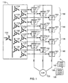
- FIG. 1 illustrates a drive circuit comprising series-connected power cells that include inverters as described in U.S. Patent No. 5,625,545 to Hammond , the disclosure of which is incorporated herein by reference in its entirety.
- a transformer 110 delivers three-phase, medium-voltage power to a load 130 such as a three-phase induction motor via an array of power cells.
- the transformer 110 includes a primary winding 112 that excites any number of secondary windings 114 -125. Although primary winding 112 is illustrated as having a star configuration, a mesh configuration is also possible.
- secondary windings 114 -125 are illustrated as having a mesh configuration, star-configured secondary windings are possible, or a combination of star and mesh windings may be used. Further, the number of secondary windings illustrated in FIG. 1 is merely exemplary, and other numbers of secondary windings are possible.
- the circuit may be used for medium voltage applications or, in some embodiments, other applications.
- a local control system 192 may be used to control each power cell, such as for turning transistors in each cell on or off. In some embodiments, the local control system 192 may be directed by a central control system 195 via a wireless or wired communications network 190.
- Each secondary winding is electrically connected to a dedicated power cell 151-153, 161-163, 171-173 and 181-183 so that three phases of series-connected power cells are connected to deliver three-phase power to a load 130.
- the number of cells per phase depicted in FIG. 1 is exemplary, and more or less than four cells per phase may be possible in various embodiments.
- three power cells may be used for each of the three phase output lines.
- five power cells may be used for each of the three phase output lines.
- Such an embodiment may have eleven voltage states which may include approximately +/-3000 volts DC (VDC), +/-2400 VDC, +/-1800 VDC, +/-1200 VDC, +/-600 VDC and zero VDC.
- US6151227 refers to a multi-level output three phase power converter which receives power from a transformer and supplies power to a load.
- a variable frequency drive includes a plurality of power cells. Each power cell has an input to receive three-phase power from a secondary winding of a transformer, and each power cell has an output to deliver single-phase power to a phase of a three-phase motor.
- a control system controls the operation of each of the power cells. The control system is programmed to increase the output voltage of each of the power cells using overmodulation upon the occurrence of a predetermined event.
- the predetermined event may include, for example, at least one of steady-state operation of the motor, the motor having reached a predetermined percentage of rated speed, the detection of a voltage change that crosses a threshold level, or the detection of bypass of at least one of the power cells.
- a variable-frequency drive includes a plurality of power cells. Each power cell has an input to receive three-phase power from a secondary winding of a transformer. Each power cell also has an output to deliver single-phase power to a phase of a three-phase load. If the load is rated to operate at approximately 4160 volts, the drive includes fewer than twelve power cells. If the load is rated to operate at approximately 6.6 kilovolts to approximately 6.9 kilovolts, the drive includes fewer than eighteen power cells. If the load is rated to operate at approximately 10 kilovolts, the drive includes fewer than twenty-four power cells. Each power cell may be rated, for example, to operate with an input AC voltage of approximately 740 volts to approximately 780 volts.
- each power cell is rated to operate with an input AC voltage of approximately 740 volts to approximately 780 volts, the motor is rated to operate at approximately 4160V, and the drive includes less than twelve power cells.
- each power cell is rated to operate with an input AC voltage of approximately 740 volts to approximately 780 volts, the motor is rated to operate at approximately 4160V, the drive includes at least twelve cells, and at least one cell per phase provides redundancy.
- each power cell is rated to operate with an input AC of approximately 740 volts to approximately 780 volts, the motor is rated to operate at approximately 6.6 kilovolts to approximately 6.9 kilovolts, and the drive includes less than eighteen power cells.
- each power cell is rated to operate with an input AC voltage of approximately 740 volts to approximately 780 volts, the motor is rated to operate at approximately 6.6 kilovolts to approximately 6.9 kilovolts, the drive includes at least eighteen cells, and at least one cell per phase provides redundancy.
- each power cell is rated to operate with an input AC of approximately 740 volts to approximately 780 volts, the motor is rated to operate at approximately 10 kilovolts, and the drive includes less than twenty-four power cells.
- each power cell is rated to operate with an input AC voltage of approximately 740 volts to approximately 780 volts, the motor is rated to operate at approximately 10 kilovolts, the drive includes at least twenty-four cells, and at least one cell per phase provides redundancy.
- the drive also may include a control system that increases the output voltage of each of the power cells using overmodulation upon the occurrence of a predetermined event.
- a method of operating a variable frequency drive includes operating a plurality of power cells that are configured as three phases of series-connected cells to deliver power to a load.
- the method includes increasing the output voltage of each power cell using overmodulation.
- the use of overmodulation may be performed under a steady-state condition, and it also may be performed under a transient condition.
- the overmodulation technique may include sinusoidal modulation, sinusoidal modulation with third-harmonic injection, or other suitable methods.
- the output voltage increase may be, for example, up to approximately 10.2% above the cells' normal output voltage at the supplied input voltage.
- the method also may include monitoring the operating speed of the load, and only permitting the use of overmodulation when the operating speed is at or above a predetermined level, such as is approximately 95% of the maximum speed of the load.
- the method also may include monitoring the power cells to detect when a power cell has been bypassed, and triggering the use of overmodulation upon detection of a bypass.
- a variable frequency drive includes a plurality of power cells.
- Each power cell has an input to receive three-phase power from a secondary winding of a transformer, and each power cell has an output to deliver single-phase power to a phase of a three-phase motor.
- a control system controls the operation of each of the power cells.
- the control system is programmed to increase the output voltage of each of the power cells using overmodulation. The increase may occur during steady-state operation of the motor, or it may be triggered by the motor having reached a predetermined percentage of rated speed, the detection of a voltage drop, or the detection of bypass of at least one of the power cells, or by some other predetermined event.
- each power cell is rated to supply approximately 690 volts
- the motor is rated to operate at approximately 4160V
- the drive includes less than twelve power cells.
- each power cell may be rated to supply approximately 690 volts
- the motor may be rated to operate at approximately 4160V
- the drive may include at least twelve cells with fewer than twelve of the cells are required to drive the load at any point in time.
- each power cell may be rated to supply approximately 690 volts
- the motor may be rated to operate at approximately 6.6 kilovolts to approximately 6.9 kilovolts
- the drive may include less than eighteen power cells.
- each power cell may be rated to supply approximately 690 volts
- the motor may be rated to operate at approximately 6.6 kilovolts to approximately 6.9 kilovolts
- the drive may includes at least eighteen cells with fewer than eighteen of the cells are required to drive the load at any point in time.
- FIG. 1 depicts an exemplary circuit comprising a plurality of power cells connected to a load.
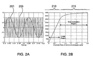
- FIGs. 2A and 2B illustrate an example of overmodulation.
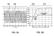
- FIGs. 3A and 3B illustrate an example of overmodulation with third-harmonic injection.
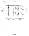
- FIG. 4 is a circuit diagram of an exemplary power cell.
- FIG. 5 is a flow diagram illustrating an exemplary overmodulation process.
- control circuit - a first electrical device that signals a second electrical device to change a state of the second electrical device.
- converter - a device that converts AC power to DC power.
- an H-bridge inverter 416 generally includes a first phase leg and a second phase leg electrically connected in parallel at the DC terminals. Each leg includes two transistor/diode combinations. In each combination, the diode is electrically coupled across the base and emitter of the transistor.
- inverter - a device that converts DC power to AC power or AC power.
- medium voltage - a rated voltage greater than 690 volts (V) and less than 69 kilovolts (kV). In some embodiments, medium voltage may be a voltage between about 1000 V and about 69 kV.
- power cell - an electrical device that has a three-phase alternating current input and a single-phase alternating current output.
- pulse-width modulation - a technique for controlling a circuit by generating variable-width pulses to represent the amplitude of an analog input signal.
- steady-state condition - a stable condition that does not substantially change over time.
- Inverters that convert a DC input to an AC output are often controlled using one or more pulse-width modulation (PWM) techniques.
- PWM pulse-width modulation
- One such technique is sinusoidal modulation.
- a sinusoidal voltage reference i.e., a control signal with amplitude V control
- a triangular waveform with amplitude V tri .
- the amplitude and frequency of the triangular waveform are typically constant, and the frequency of the triangular waveform establishes the inverter's switching frequency.
- Sinusoidal modulation allows linear control of the output voltage until the amplitude of a sinusoidal voltage reference is equal to the amplitude of the triangular carrier.
- FIG. 2A shows the two signals that are compared in sinusoidal modulation v control 201 and v tri 205.
- FIG. 2B shows the output voltage as a function of modulation index. As shown in FIG. 2B , the amplitude of the fundamental frequency component of the output voltage linearly varies with the amplitude of the reference signal in the linear region 210. However, the voltage output does not linearly increase with the amplitude of the reference signal after it exceeds the amplitude of the triangular carrier, i.e., when the modulation index exceeds 1.0 and the overmodulation region 215 is entered.
- the inverter output voltage is 3500 volts (V) when the modulation index is 1.0, although the present invention is not limited to such an embodiment.
- FIG. 3A illustrates the two signals, v control 301 and v tri 305, that may be compared in a sinusoidal modulation with third-harmonic injection method.
- FIG. 3B illustrates an exemplary output voltage as a function of modulation index. As shown in FIG. 3B , the voltage output is linear until the modulation index reaches 1.155.
- the output voltage is 4040V, which is correspondingly higher than the linear control limit with sinusoidal modulation. Above this modulation index linearity is lost, i.e., when the amplitude of the reference signal exceeds 1.155 times the amplitude of the triangular carrier. Increasing the amplitude of the sinusoidal voltage references above this linear control limit of 115.5% can increase voltage output above 115.5%.
- the maximum output of the inverter in the over-modulation region is 127.3% of the voltage produced with a modulation index of 1.0. This is achieved when the sinusoidal reference amplitude is increased beyond 320% of the triangular carrier signal (i.e., when the modulation index is greater than 3.2).
- Operation in the over-modulation region may occur in situations when the inverter output is required to be maximized under input transient conditions, such as a sudden loss of the source voltage in the inverter.
- the inverter attempts to maintain maximum possible output voltage by increasing the voltage reference amplitude and operating in the over-modulation region. Once the source voltage is restored, the inverter operates in the linear region to limit the production of lower order harmonics on the output and prevent any long term side-effects of such harmonics from affecting the load.
- the use of over-modulation in steady state operation of series-connected inverters may provide one or more advantages in certain embodiments. For example, by intentionally forcing a power cell to operate in the overmodulation region in steady-state operation, the inverter may deliver the same output voltage as it would in the linear region, but with lower source voltage (for example, approximately 10% lower) being delivered to the inverter.
- the components in the inverter, or the input transformer may be rated at a lower voltage and thus could be less expensive or smaller than with higher-rated components.
- such operation (with overmodulation) may provide a higher output voltage (for example, approximately 10% higher), with the same source voltage being delivered to the inverter.
- FIG. 4 is a circuit diagram that illustrates exemplary components of a power cell that may be used in a circuit such as that of FIG. 1 .
- a prior art power cell 410 may include a three-phase diode-bridge rectifier 412, one or more direct current (DC) capacitors 414, and an H-bridge or other inverter 416.
- the rectifier 412 converts the input 418 AC voltage to a substantially constant DC voltage that is supported by the capacitors 414 that are connected across the rectifier 412 output.
- the output stage of the inverter 410 includes an H-bridge inverter 416 includes two poles, a left pole and a right pole, each with two devices.
- the inverter 410 transforms the DC voltage across the DC capacitors 414 to an AC output 420 using pulse-width modulation (PWM) of the semiconductor devices in the H-bridge inverter 416.
- PWM pulse-width modulation
- Outputs of the H-Bridge inverters may be connected in series (as shown in FIG. 1 ) to build up the output voltage.
- Other circuit configurations may be used for a power cell instead of the circuit illustrated in FIG. 4 .
- Series-connected inverters such as those shown in FIGs. 1 and 4 are typically used in medium-voltage AC motor drive applications. Accordingly, the embodiments described herein include operating a circuit of series-connected inverters so that each inverter is operated in the overmodulation region. For a power cell that normally receives (or operates with a transformer secondary winding voltage of) 690V, an increase of up to 750V (i.e., an increase of approximately 8.7%), or even an increase of up to 780V (i.e., an approximately 13% increase) may be desirable.
- Motors are available only at a few discrete voltage levels that are industry standard, and only some of these levels are extremely popular. Although the invention is not limited to current industry standard voltage levels, the examples listed below describe the use of over-modulation with series-connected inverters at two exemplary voltage levels.
- K ovm represents the increase in output voltage due to operation with overmodulation and is the range of 1.0 ⁇ K ovm ⁇ 1.10. This expression shows that increasing both the AC input voltage to the power cells and the K ovm factor to their practical limits can reduce the number of ranks required to produce a given output voltage. This is illustrated using examples in the following paragraphs.
- a drive such as that shown in FIG. 1 with series-connected inverters such as those shown in FIG. 4 may be used.
- the typical drive in the prior art has four series-connected (single-phase) inverters per phase.
- the typical drive in the prior art has four series-connected (single-phase) inverters per phase.
- the typical drive in the prior art has four series-connected (single-phase) inverters per phase.
- Each inverter which may use insulated gate bipolar transistors (IGBTs) or other suitable devices rated at approximately 1700V, receives a 690V AC source and is capable of delivering approximately 709V at the output for a total output of approximately 4912V phase-to-phase (or approximately 2836V per phase).
- IGBTs insulated gate bipolar transistors
- Such an inverter is capable of producing well over the required voltage of 4160V.
- a small increase in the input source voltage to 740V in each single-phase inverter can provide approximately 4347V phase-to-phase. This is sufficient for the 4160V desired output.
- the small increase in source voltage can be accommodated with existing IGBT ratings and will not need transistors that are rated for the next higher voltage rating.
- a slight increase in capacitor rating of the inverter i.e., element 414 of FIG. 4
- this arrangement which uses only three inverters per-phase, may result in overall size and cost savings.
- FIG. 1 Another popular voltage level is 6900V for which the drive of FIG. 1 may be used.
- this drive may be modified to have six series-connected (single-phase) inverters per phase (i.e., six ranks).
- Each inverter such as that shown in FIG. 4 which may use IGBTs rated at 1700V, receives a 690V AC source and is capable of approximately 709V at the output for a total output of approximately 4254V per phase, or approximately 7368V phase-to-phase.
- Such an inverter may be capable of producing well over the required voltage of 4160V.
- the total output voltage would be approximately 6140V phase-to-phase (or approximately 3545V per phase). This voltage level is well below the desired output of 6900V. If over-modulation is used, then the three series-connected inverters in per-phase arrangement may provide approximately 6754V phase-to-phase (or approximately 3900V per phase) which is slightly less than the desired voltage output.
- a small increase in the input source voltage to 740V in each single-phase inverter can provide approximately 7243V phase-phase. This is sufficient for the 6900V desired output.
- the small increase in source voltage can be accommodated with existing IGBT ratings and will not need transistors that are rated for the next higher voltage rating.
- a slight increase in capacitor rating of the inverter i.e., element 414 of FIG. 4
- this arrangement which uses only five inverters per-phase, also may result in overall size or cost savings.
- a further increase in the input source voltage to each cell from 740V to 750V may be desirable to compensate for voltage drops such as those due to transformer leakage impedance.
- a drive having 24 series-connected power cells i.e., 8 ranks of cells
- each rated to operate with an input AC voltage of between about 740V and 780 V may be used in the prior art.
- overmodulation fewer than 24 cells, such as seven ranks of cells could be used to drive the load.
- 8 or more ranks could be used, with one rank providing redundancy as only seven are required to drive the load when overmodulation is triggered.
- the methods described herein may include using a control system (i.e., element 192 in FIG. 1 ) to operate a drive such as that shown in FIG. 1 by introducing reference and carrier signals so that the power cell is operated in an overmodulation region 510.
- operation in the overmodulation region may occur on all cells in the power circuit during normal - i.e., steady-state - operation of the circuit to drive a motor.
- over modulation may also occur during transient operation.
- control system may monitor the drive to determine whether one or more of the cells has failed or otherwise been bypassed 515, and the control circuit may trigger overmodulation 525 in order to maintain a substantially full output voltage despite the loss of one or more cells.
- overmodulation also may be triggered by the occurrence of one or more events.
- overmodulation may be triggered by detecting that the input voltage has crossed a predetermined threshold, such as detecting that voltage to the load has dropped below a predetermined level 530 or increased above a predetermined level 550.
- a predetermined threshold such as detecting that voltage to the load has dropped below a predetermined level 530 or increased above a predetermined level 550.
- the input voltage to the series-connected inverters may be monitored, or the desired voltage delivered to the load may be monitored, and overmodulation may be triggered.
- the trigger may be based on a first predetermined level, such as a voltage drop that results in the input voltage dropping to or below approximately 95% of a predetermined or rated level.
- the trigger may be based on an increase of the desired load voltage above a certain level, such as approximately 95% of the rated motor voltage
- overmodulation may be limited to operating conditions that are between about 95% and about 100% of rated speed, or conditions that are between about 97% and about 100% of desired maximum speed, or at other desired conditions.
- overmodulation may be controlled to be triggered by a combination of factors, such as the detection of a cell bypass and change in the operating speed.
- the pretedetermined threshold speed and voltage levels may differ 517, 518, depending on whether a cell bypass has been detected 515.
- the control system may apply any now or hereafter known overmodulation techniques to accomplish the goals described herein.
- the techniques described in Hava “Carrier-Based PWM-VSI Drives in the Overmodulation Region", published as a Ph.D thesis December 1998 at the University of Wisconsin-Madison (Madison, Wisconsin, U.S.A.) may be used.
- overmodulation may result in each power cell having an output voltage that is between approximately 0% and approximately 10.2% higher than its normal operation based on the input voltage. In other embodiments, overmodulation may result in each power cell having an output voltage that is between approximately 2% and approximately 10% higher than its normal operation. In other embodiments, overmodulation may result in each power cell having an output voltage that is approximately 2.7% higher than its normal operation.
- the circuits that would normally be used to drive a load could instead serve to provide redundancy in the event of a power cell failure.
- FIG. 1 in a circuit where power cells are rated to operate with an input AC voltage of 690V, four ranks of cells 150,160,170 and 180 are normally required to drive a load of 4160V or approximately 4 kilovolts (kV). Each rank includes three power cells - one cell per phase - and under normal operation the circuits therefore normally require twelve power cells 151-153,161-163,171-173 and 181-183.
- each power cell is operated with an input AC voltage of approximately 740V to approximately 780V
- only three ranks 150,160 and 170 i.e., nine power cells 151-153,161-163, 171-173
- the fourth rank 180 could be omitted as mentioned in Example 1 above.
- the fourth rank 180 could be included in the circuit but only used to provide a redundancy of one power cell per phase for a 4160V rated motor voltage.
- a circuit that drives a load at approximately 6.6 kV or approximately 6.9 kV six ranks of power cells (i.e., eighteen total power cells) if the power cells are rated to operate with an input AC voltage of approximately 690V.
- this circuit could supply 6900V to the load using and only five ranks (i.e., fifteen power cells) as described in Example 2 above.
- the sixth rank could be omitted from the circuit, or it could be included in the circuit to provide redundant power cells.
- the selection of power cells is not limited to the embodiments described herein, and any number of power cells can be selected based on the desired voltage that must be supplied to power a load.
Landscapes
- Engineering & Computer Science (AREA)
- Power Engineering (AREA)
- Inverter Devices (AREA)
- Control Of Ac Motors In General (AREA)
Abstract
Claims (10)
- Entraînement à fréquence variable, comprenant un système de commande qui augmente la tension de sortie de chacun des éléments de puissance (151-153 ; 161-163 ; 171-173 ; 181-183) en utilisant la surmodulation lors de la survenue d'un évènement prédéterminé, et comprenant par ailleurs une pluralité d'éléments de puissance (151-153 ; 161-163 ; 171-173 ; 181-183), dans lequel :chaque élément de puissance (151-153 ; 161-163 ; 171-173 ; 181-183) a une entrée pour recevoir du courant triphasé d'un enroulement secondaire de transformateur ;chaque élément de puissance (151-153 ; 161-163 ; 171-173 ; 181-183) a une sortie pour fournir du courant monophasé à une phase d'une charge triphasée (130) ;si la charge est prévue pour fonctionner à approximativement 4 160 volts, la pluralité d'éléments de puissance (151-153 ; 161-163 ; 171-173 ; 181-183) comprend moins de douze éléments de puissance ;si la charge est prévue pour fonctionner d'approximativement 6,6 kilovolts à approximativement 6,9 kilovolts, la pluralité d'éléments de puissance (151-153 ; 161-163 ; 171-173 ; 181-183) comprend moins de dix-huit éléments de puissance, etsi la charge est prévue pour fonctionner à approximativement 10 kilovolts, la pluralité d'éléments de puissance (151-153 ; 161-163 ; 171-173 ; 181-183) comprend moins de vingt-quatre éléments de puissance.
- Entraînement selon la revendication 1, dans lequel la charge est constituée d'un moteur triphasé (130).
- Entraînement selon la revendication 2, dans lequel chaque élément de puissance (151-153 ; 161-163 ; 171-173 ; 181-183) est prévu pour fonctionner à une tension alternative d'entrée d'approximativement 740 volts à approximativement 780 volts, le moteur est prévu pour fonctionner à approximativement 4 160 V et l'entraînement comprend moins de douze éléments de puissance.
- Entraînement selon la revendication 2, dans lequel chaque élément de puissance (151-153 ; 161-163 ; 171-173 ; 181-183) est prévu pour fonctionner à une tension alternative d'entrée d'approximativement 740 volts à approximativement 780 volts, le moteur est prévu pour fonctionner à approximativement 4 160 V, l'entraînement comprend au moins douze éléments de puissance et au moins un élément par phase fournit une redondance.
- Entraînement selon la revendication 2, dans lequel chaque élément de puissance (151-153 ; 161-163 ; 171-173 ; 181-183) est prévu pour fonctionner à une tension alternative d'entrée d'approximativement 740 volts à approximativement 780 volts, le moteur est prévu pour fonctionner d'approximativement 6,6 kilovolts à approximativement 6,9 kilovolts et l'entraînement comprend moins de dix-huit éléments de puissance.
- Entraînement selon la revendication 2, dans lequel chaque élément de puissance (151-153 ; 161-163 ; 171-173 ; 181-183) est prévu pour fonctionner à une tension alternative d'entrée d'approximativement 740 volts à approximativement 780 volts, le moteur est prévu pour fonctionner d'approximativement 6,6 kilovolts à approximativement 6,9 kilovolts, l'entraînement comprend au moins dix-huit éléments de puissance et au moins un élément par phase fournit une redondance.
- Entraînement selon la revendication 2, dans lequel chaque élément de puissance (151-153 ; 161-163 ; 171-173 ; 181-183) est prévu pour fonctionner à une tension alternative d'entrée d'approximativement 740 volts à approximativement 780 volts, le moteur est prévu pour fonctionner à approximativement 10 kilovolts et l'entraînement comprend moins de vingt-quatre éléments de puissance.
- Entraînement selon la revendication 2, dans lequel chaque élément de puissance (151-153 ; 161-163 ; 171-173 ; 181-183) est prévu pour fonctionner à une tension alternative d'entrée d'approximativement 740 volts à approximativement 780 volts, le moteur est prévu pour fonctionner à approximativement 10 kilovolts, l'entraînement comprend au moins vingt-quatre éléments de puissance et au moins un élément par phase fournit une redondance.
- Entraînement selon la revendication 1, dans lequel chaque élément de puissance (151-153 ; 161-163 ; 171-173 ; 181-183) est prévu pour fonctionner à une tension alternative d'entrée d'approximativement 740 volts à approximativement 780 volts.
- Entraînement selon la revendication 9, dans lequel l'évènement prédéterminé consiste au moins en l'un des évènements parmi le fonctionnement en régime permanent du moteur, le moteur ayant atteint un pourcentage prédéterminé de sa vitesse nominale, la détection d'une variation de tension qui passe par un niveau seuil, ou la détection de la mise hors circuit d'au moins l'un des éléments de puissance (151-153 ; 161-163 ; 171-173 ; 181-183).
Applications Claiming Priority (2)
| Application Number | Priority Date | Filing Date | Title |
|---|---|---|---|
| US68531105P | 2005-05-27 | 2005-05-27 | |
| PCT/US2006/020373 WO2006130452A2 (fr) | 2005-05-27 | 2006-05-26 | Fonctionnement d'un onduleur a surmodulation |
Publications (2)
| Publication Number | Publication Date |
|---|---|
| EP1884015A2 EP1884015A2 (fr) | 2008-02-06 |
| EP1884015B1 true EP1884015B1 (fr) | 2011-06-29 |
Family
ID=36972677
Family Applications (1)
| Application Number | Title | Priority Date | Filing Date |
|---|---|---|---|
| EP06771255A Expired - Fee Related EP1884015B1 (fr) | 2005-05-27 | 2006-05-26 | Fonctionnement d'un onduleur a surmodulation |
Country Status (9)
| Country | Link |
|---|---|
| US (1) | US7307400B2 (fr) |
| EP (1) | EP1884015B1 (fr) |
| KR (1) | KR100984496B1 (fr) |
| CN (1) | CN101180785B (fr) |
| BR (1) | BRPI0610651B1 (fr) |
| CA (1) | CA2609798C (fr) |
| MX (1) | MX2007014842A (fr) |
| RU (2) | RU2007149319A (fr) |
| WO (1) | WO2006130452A2 (fr) |
Families Citing this family (18)
| Publication number | Priority date | Publication date | Assignee | Title |
|---|---|---|---|---|
| US8125177B2 (en) * | 2008-06-13 | 2012-02-28 | Baker Hughes Incorporated | System and method for adding voltages of power modules in variable frequency drives |
| DE102008036811B4 (de) * | 2008-08-07 | 2019-10-10 | Siemens Aktiengesellschaft | Redundanzsteuerverfahren eines mehrphasigen Stromrichters mit verteilten Energiespeichern |
| NO332673B1 (no) * | 2008-11-24 | 2012-12-03 | Aker Engineering & Technology | Frekvensomformer |
| CN102498656B (zh) * | 2009-09-15 | 2014-08-27 | Abb研究有限公司 | 电压源换流器,用于控制电压源换流器的方法和控制装置 |
| US8760089B2 (en) * | 2009-11-30 | 2014-06-24 | Franklin Electric Company, Inc. | Variable speed drive system |
| JP5013283B2 (ja) * | 2010-02-17 | 2012-08-29 | 株式会社安川電機 | マトリクスコンバータの制御装置 |
| ES2395460B2 (es) * | 2011-05-31 | 2014-05-23 | Universidad Carlos Iii De Madrid | Método y dispositivo de transformación de corriente continua en corriente alterna |
| US8664903B2 (en) | 2011-06-27 | 2014-03-04 | Franklin Electric Company, Inc. | Adaptive flux control drive |
| KR20130039612A (ko) * | 2011-10-12 | 2013-04-22 | 엘에스산전 주식회사 | 회생형 고압 인버터 |
| FR2982092B1 (fr) * | 2011-11-02 | 2015-01-02 | Valeo Systemes De Controle Moteur | Module de puissance et dispositif electrique pour l'alimentation et la charge combinees respectivement d'un accumulateur et d'un moteur |
| JP6014061B2 (ja) * | 2014-01-22 | 2016-10-25 | 東芝三菱電機産業システム株式会社 | 無停電電源システム |
| EP2975621A1 (fr) * | 2014-07-15 | 2016-01-20 | Siemens Aktiengesellschaft | Batterie de condensateur |
| GB201610369D0 (en) * | 2016-06-15 | 2016-07-27 | Rolls Royce Plc | Control of an electrical converter |
| WO2018226025A1 (fr) * | 2017-06-07 | 2018-12-13 | 엘지전자 주식회사 | Appareil d'entraînement d'un moteur |
| DE102017131042A1 (de) | 2017-12-21 | 2019-06-27 | Sma Solar Technology Ag | Umrichter mit mindestens einem wandlermodul mit drei brückenzweigen, verfahren zum betreiben und verwendung eines solchen umrichters |
| CN113016113A (zh) * | 2018-11-15 | 2021-06-22 | 西门子股份公司 | 无输入功率的变频驱动器的延长制动 |
| WO2020142661A1 (fr) * | 2019-01-04 | 2020-07-09 | Siemens Aktiengesellschaft | Réduction de distorsion harmonique d'entrée dans une alimentation électrique |
| CN113872494B (zh) * | 2021-09-14 | 2023-03-21 | 湖南三一中益机械有限公司 | 电机堵转保护控制方法、装置和电动铣刨机 |
Family Cites Families (21)
| Publication number | Priority date | Publication date | Assignee | Title |
|---|---|---|---|---|
| JPS6152179A (ja) * | 1984-08-22 | 1986-03-14 | Toshiba Corp | 電動機駆動用電源装置 |
| JP2814837B2 (ja) * | 1992-06-04 | 1998-10-27 | 株式会社日立製作所 | 電力変換装置 |
| ZA949795B (en) * | 1993-12-17 | 1995-08-18 | Hitachi Ltd | Electric power conversion equipment. |
| JP3455788B2 (ja) * | 1993-12-17 | 2003-10-14 | 株式会社日立製作所 | 電力変換装置 |
| JP3747259B2 (ja) | 1993-12-17 | 2006-02-22 | 株式会社日立製作所 | 電気車の制御装置 |
| US5625545A (en) * | 1994-03-01 | 1997-04-29 | Halmar Robicon Group | Medium voltage PWM drive and method |
| US5638263A (en) * | 1994-03-01 | 1997-06-10 | Halmar Robicon Group | Low and medium voltage PWM AC/DC power conversion method and apparatus |
| JP3395920B2 (ja) * | 1994-07-05 | 2003-04-14 | 株式会社デンソー | インバータ制御装置 |
| DE19614627A1 (de) * | 1996-04-13 | 1997-10-16 | Abb Patent Gmbh | Hochspannungs-Stromrichtersystem |
| KR100326104B1 (ko) * | 1997-08-04 | 2002-10-11 | 가부시끼가이샤 도시바 | 전력변환장치의제어방법 |
| US6014323A (en) * | 1997-08-08 | 2000-01-11 | Robicon Corporation | Multiphase power converter |
| GB2330254B (en) * | 1997-10-09 | 2000-10-18 | Toshiba Kk | Multiple inverter system |
| US6262555B1 (en) * | 1998-10-02 | 2001-07-17 | Robicon Corporation | Apparatus and method to generate braking torque in an AC drive |
| US6301130B1 (en) * | 1999-09-01 | 2001-10-09 | Robicon Corporation | Modular multi-level adjustable supply with parallel connected active inputs |
| US6313600B1 (en) * | 2000-02-29 | 2001-11-06 | Robicon Corporation | Control method and apparatus for insufficient input voltage in an AC drive |
| DE10106245A1 (de) | 2001-01-10 | 2002-07-11 | Itg Induktionstechnik Gmbh | Verfahren zur Speisung eines Rinnenofens |
| US6590361B2 (en) * | 2001-07-19 | 2003-07-08 | Delphi Technologies, Inc. | Method and system for controlling an induction machine |
| AU2003238635A1 (en) * | 2002-07-15 | 2004-02-02 | Koninklijke Philips Electronics N.V. | Inverter |
| US6969967B2 (en) * | 2003-12-12 | 2005-11-29 | Ut-Battelle Llc | Multi-level dc bus inverter for providing sinusoidal and PWM electrical machine voltages |
| FR2875970B1 (fr) * | 2004-09-27 | 2008-01-18 | Schneider Electric Ind Sas | Dispositif et procede de commande d'un convertisseur d'energie electrique et convertisseur comportant un tel dispositif |
| US8749839B2 (en) | 2005-03-24 | 2014-06-10 | Kofax, Inc. | Systems and methods of processing scanned data |
-
2006
- 2006-05-26 CN CN2006800180864A patent/CN101180785B/zh active Active
- 2006-05-26 US US11/420,578 patent/US7307400B2/en active Active
- 2006-05-26 EP EP06771255A patent/EP1884015B1/fr not_active Expired - Fee Related
- 2006-05-26 WO PCT/US2006/020373 patent/WO2006130452A2/fr active Application Filing
- 2006-05-26 RU RU2007149319/09A patent/RU2007149319A/ru unknown
- 2006-05-26 BR BRPI0610651-0A patent/BRPI0610651B1/pt not_active IP Right Cessation
- 2006-05-26 KR KR1020077030388A patent/KR100984496B1/ko active IP Right Grant
- 2006-05-26 MX MX2007014842A patent/MX2007014842A/es active IP Right Grant
- 2006-05-26 CA CA2609798A patent/CA2609798C/fr active Active
-
2009
- 2009-10-09 RU RU2009137559/22U patent/RU93000U1/ru active
Also Published As
| Publication number | Publication date |
|---|---|
| WO2006130452A3 (fr) | 2007-04-05 |
| BRPI0610651B1 (pt) | 2018-08-07 |
| US7307400B2 (en) | 2007-12-11 |
| KR20080015029A (ko) | 2008-02-15 |
| WO2006130452A2 (fr) | 2006-12-07 |
| MX2007014842A (es) | 2008-02-21 |
| US20060279249A1 (en) | 2006-12-14 |
| BRPI0610651A2 (pt) | 2010-07-13 |
| EP1884015A2 (fr) | 2008-02-06 |
| KR100984496B1 (ko) | 2010-10-01 |
| CA2609798C (fr) | 2012-03-20 |
| RU2007149319A (ru) | 2009-07-10 |
| RU93000U1 (ru) | 2010-04-10 |
| CN101180785A (zh) | 2008-05-14 |
| CA2609798A1 (fr) | 2006-12-07 |
| CN101180785B (zh) | 2010-05-26 |
Similar Documents
| Publication | Publication Date | Title |
|---|---|---|
| EP1884015B1 (fr) | Fonctionnement d'un onduleur a surmodulation | |
| US6747881B2 (en) | Frequency converter | |
| US8476859B2 (en) | DC power for SGCT devices using a high frequency current loop with multiple current transformers | |
| EP2030312B1 (fr) | Procédé de commande d'un convertisseur à trois niveaux | |
| CA2230500C (fr) | Convertisseur de puissance et procede de conversion de puissance | |
| EP3059847B1 (fr) | Dispositif de conversion de puissance et procédé de conversion de puissance | |
| EP3300240A1 (fr) | Piles à combustible de secours sur demande pour convertisseur de puissance multiniveau modulaire | |
| WO2006026217A2 (fr) | Convertisseur de puissance multiniveau sans transformateur | |
| US9929676B2 (en) | Method for controlling three phase equivalent voltage of multilevel inverter | |
| EP2830210B1 (fr) | Appareil d'excitation de générateur et système de conversion de puissance | |
| JPH11122943A (ja) | 多重インバータ装置及びその制御方法 | |
| JP6685477B1 (ja) | 電力変換装置、および電力変換システム | |
| CN112640280B (zh) | 具有控制装置和无源频率滤波器的多相多级变流器以及用于控制多相多级装置变流器的方法 | |
| US20160380551A1 (en) | Converter arrangement having multi-step converters connected in parallel and method for controlling these | |
| EP3375082B1 (fr) | Convertisseur modulaire multiniveaux pour gestion de défauts côté ca | |
| JP4011534B2 (ja) | 多重変換器で構成される直流送電設備及びその運転方法 | |
| Baros et al. | Multilevel inverters for motor drives and wireless power transfer applications | |
| JPH11252992A (ja) | 電力変換装置 | |
| US8284577B2 (en) | Method for operation of a converter circuit, and apparatus for carrying out the method | |
| Sengolrajan et al. | Three Phase Trinary Source MLI Using Multicarrier SPWM Strategies | |
| US20120127763A1 (en) | Electric power supply system comprising power modules coupled in parallel | |
| JP5181712B2 (ja) | 多重インバータシステム | |
| ZAKIR et al. | Simulation and Analysis of Capacitor Voltage-Balancing Method for NNPC Inverter |
Legal Events
| Date | Code | Title | Description |
|---|---|---|---|
| PUAI | Public reference made under article 153(3) epc to a published international application that has entered the european phase |
Free format text: ORIGINAL CODE: 0009012 |
|
| 17P | Request for examination filed |
Effective date: 20071112 |
|
| AK | Designated contracting states |
Kind code of ref document: A2 Designated state(s): CH DE FR IT LI |
|
| RBV | Designated contracting states (corrected) |
Designated state(s): CH DE FR IT LI |
|
| DAX | Request for extension of the european patent (deleted) | ||
| 17Q | First examination report despatched |
Effective date: 20090617 |
|
| RAP1 | Party data changed (applicant data changed or rights of an application transferred) |
Owner name: SIEMENS INDUSTRY, INC. |
|
| GRAP | Despatch of communication of intention to grant a patent |
Free format text: ORIGINAL CODE: EPIDOSNIGR1 |
|
| GRAS | Grant fee paid |
Free format text: ORIGINAL CODE: EPIDOSNIGR3 |
|
| GRAA | (expected) grant |
Free format text: ORIGINAL CODE: 0009210 |
|
| AK | Designated contracting states |
Kind code of ref document: B1 Designated state(s): CH DE FR IT LI |
|
| REG | Reference to a national code |
Ref country code: CH Ref legal event code: EP |
|
| REG | Reference to a national code |
Ref country code: CH Ref legal event code: NV Representative=s name: SIEMENS SCHWEIZ AG |
|
| REG | Reference to a national code |
Ref country code: DE Ref legal event code: R096 Ref document number: 602006022801 Country of ref document: DE Effective date: 20110825 |
|
| PLBE | No opposition filed within time limit |
Free format text: ORIGINAL CODE: 0009261 |
|
| STAA | Information on the status of an ep patent application or granted ep patent |
Free format text: STATUS: NO OPPOSITION FILED WITHIN TIME LIMIT |
|
| 26N | No opposition filed |
Effective date: 20120330 |
|
| REG | Reference to a national code |
Ref country code: DE Ref legal event code: R097 Ref document number: 602006022801 Country of ref document: DE Effective date: 20120330 |
|
| REG | Reference to a national code |
Ref country code: CH Ref legal event code: PUE Owner name: SIEMENS AKTIENGESELLSCHAFT, DE Free format text: FORMER OWNER: SIEMENS INDUSTRY, INC., US |
|
| REG | Reference to a national code |
Ref country code: DE Ref legal event code: R082 Ref document number: 602006022801 Country of ref document: DE Representative=s name: MAIER, DANIEL OLIVER, DIPL.-ING. UNIV., DE |
|
| REG | Reference to a national code |
Ref country code: DE Ref legal event code: R081 Ref document number: 602006022801 Country of ref document: DE Owner name: SIEMENS AKTIENGESELLSCHAFT, DE Free format text: FORMER OWNER: SIEMENS INDUSTRY, INC., BUFFALO GROVE, ILL., US Effective date: 20150429 Ref country code: DE Ref legal event code: R082 Ref document number: 602006022801 Country of ref document: DE Representative=s name: MAIER, DANIEL OLIVER, DIPL.-ING. UNIV., DE Effective date: 20150429 |
|
| REG | Reference to a national code |
Ref country code: FR Ref legal event code: TP Owner name: SIEMENS AKTIENGESELLSCHAFT, DE Effective date: 20150626 |
|
| REG | Reference to a national code |
Ref country code: FR Ref legal event code: PLFP Year of fee payment: 11 |
|
| REG | Reference to a national code |
Ref country code: FR Ref legal event code: PLFP Year of fee payment: 12 |
|
| REG | Reference to a national code |
Ref country code: CH Ref legal event code: PCOW Free format text: NEW ADDRESS: WERNER-VON-SIEMENS-STRASSE 1, 80333 MUENCHEN (DE) |
|
| REG | Reference to a national code |
Ref country code: FR Ref legal event code: PLFP Year of fee payment: 13 |
|
| PGFP | Annual fee paid to national office [announced via postgrant information from national office to epo] |
Ref country code: DE Payment date: 20190719 Year of fee payment: 14 |
|
| PGFP | Annual fee paid to national office [announced via postgrant information from national office to epo] |
Ref country code: CH Payment date: 20190802 Year of fee payment: 14 |
|
| PGFP | Annual fee paid to national office [announced via postgrant information from national office to epo] |
Ref country code: FR Payment date: 20200518 Year of fee payment: 15 |
|
| PGFP | Annual fee paid to national office [announced via postgrant information from national office to epo] |
Ref country code: IT Payment date: 20200525 Year of fee payment: 15 |
|
| REG | Reference to a national code |
Ref country code: DE Ref legal event code: R119 Ref document number: 602006022801 Country of ref document: DE |
|
| PG25 | Lapsed in a contracting state [announced via postgrant information from national office to epo] |
Ref country code: CH Free format text: LAPSE BECAUSE OF NON-PAYMENT OF DUE FEES Effective date: 20200531 Ref country code: LI Free format text: LAPSE BECAUSE OF NON-PAYMENT OF DUE FEES Effective date: 20200531 |
|
| PG25 | Lapsed in a contracting state [announced via postgrant information from national office to epo] |
Ref country code: DE Free format text: LAPSE BECAUSE OF NON-PAYMENT OF DUE FEES Effective date: 20201201 |
|
| PG25 | Lapsed in a contracting state [announced via postgrant information from national office to epo] |
Ref country code: FR Free format text: LAPSE BECAUSE OF NON-PAYMENT OF DUE FEES Effective date: 20210531 |
|
| PG25 | Lapsed in a contracting state [announced via postgrant information from national office to epo] |
Ref country code: IT Free format text: LAPSE BECAUSE OF NON-PAYMENT OF DUE FEES Effective date: 20200526 |