EP1880096B1 - Procede et dispositif de commande electrique d'une soupape au moyen d'un element de fermeture mecanique - Google Patents
Procede et dispositif de commande electrique d'une soupape au moyen d'un element de fermeture mecanique Download PDFInfo
- Publication number
- EP1880096B1 EP1880096B1 EP06742322A EP06742322A EP1880096B1 EP 1880096 B1 EP1880096 B1 EP 1880096B1 EP 06742322 A EP06742322 A EP 06742322A EP 06742322 A EP06742322 A EP 06742322A EP 1880096 B1 EP1880096 B1 EP 1880096B1
- Authority
- EP
- European Patent Office
- Prior art keywords
- duty cycle
- pwm
- value
- low
- period
- Prior art date
- Legal status (The legal status is an assumption and is not a legal conclusion. Google has not performed a legal analysis and makes no representation as to the accuracy of the status listed.)
- Active
Links
- 238000000034 method Methods 0.000 title claims description 16
- 238000012937 correction Methods 0.000 claims description 23
- 238000001914 filtration Methods 0.000 claims description 4
- 230000006978 adaptation Effects 0.000 claims description 2
- 238000010586 diagram Methods 0.000 description 8
- 230000000694 effects Effects 0.000 description 6
- 238000013459 approach Methods 0.000 description 5
- 230000001419 dependent effect Effects 0.000 description 3
- 230000000712 assembly Effects 0.000 description 1
- 238000000429 assembly Methods 0.000 description 1
- 230000035559 beat frequency Effects 0.000 description 1
- 230000005540 biological transmission Effects 0.000 description 1
- 125000004122 cyclic group Chemical group 0.000 description 1
- 230000005520 electrodynamics Effects 0.000 description 1
- 230000002349 favourable effect Effects 0.000 description 1
- 238000005259 measurement Methods 0.000 description 1
- 238000012544 monitoring process Methods 0.000 description 1
- 230000007935 neutral effect Effects 0.000 description 1
- 230000000737 periodic effect Effects 0.000 description 1
- 230000003068 static effect Effects 0.000 description 1
- 238000011144 upstream manufacturing Methods 0.000 description 1
Images

Classifications
-
- F—MECHANICAL ENGINEERING; LIGHTING; HEATING; WEAPONS; BLASTING
- F16—ENGINEERING ELEMENTS AND UNITS; GENERAL MEASURES FOR PRODUCING AND MAINTAINING EFFECTIVE FUNCTIONING OF MACHINES OR INSTALLATIONS; THERMAL INSULATION IN GENERAL
- F16K—VALVES; TAPS; COCKS; ACTUATING-FLOATS; DEVICES FOR VENTING OR AERATING
- F16K31/00—Actuating devices; Operating means; Releasing devices
- F16K31/02—Actuating devices; Operating means; Releasing devices electric; magnetic
- F16K31/06—Actuating devices; Operating means; Releasing devices electric; magnetic using a magnet, e.g. diaphragm valves, cutting off by means of a liquid
- F16K31/0675—Electromagnet aspects, e.g. electric supply therefor
-
- H—ELECTRICITY
- H03—ELECTRONIC CIRCUITRY
- H03K—PULSE TECHNIQUE
- H03K7/00—Modulating pulses with a continuously-variable modulating signal
- H03K7/08—Duration or width modulation ; Duty cycle modulation
-
- F—MECHANICAL ENGINEERING; LIGHTING; HEATING; WEAPONS; BLASTING
- F02—COMBUSTION ENGINES; HOT-GAS OR COMBUSTION-PRODUCT ENGINE PLANTS
- F02D—CONTROLLING COMBUSTION ENGINES
- F02D41/00—Electrical control of supply of combustible mixture or its constituents
- F02D41/0025—Controlling engines characterised by use of non-liquid fuels, pluralities of fuels, or non-fuel substances added to the combustible mixtures
- F02D41/003—Adding fuel vapours, e.g. drawn from engine fuel reservoir
- F02D41/0032—Controlling the purging of the canister as a function of the engine operating conditions
- F02D41/004—Control of the valve or purge actuator, e.g. duty cycle, closed loop control of position
-
- F—MECHANICAL ENGINEERING; LIGHTING; HEATING; WEAPONS; BLASTING
- F02—COMBUSTION ENGINES; HOT-GAS OR COMBUSTION-PRODUCT ENGINE PLANTS
- F02D—CONTROLLING COMBUSTION ENGINES
- F02D41/00—Electrical control of supply of combustible mixture or its constituents
- F02D41/02—Circuit arrangements for generating control signals
- F02D41/14—Introducing closed-loop corrections
- F02D41/1401—Introducing closed-loop corrections characterised by the control or regulation method
- F02D41/1408—Dithering techniques
-
- F—MECHANICAL ENGINEERING; LIGHTING; HEATING; WEAPONS; BLASTING
- F15—FLUID-PRESSURE ACTUATORS; HYDRAULICS OR PNEUMATICS IN GENERAL
- F15B—SYSTEMS ACTING BY MEANS OF FLUIDS IN GENERAL; FLUID-PRESSURE ACTUATORS, e.g. SERVOMOTORS; DETAILS OF FLUID-PRESSURE SYSTEMS, NOT OTHERWISE PROVIDED FOR
- F15B2211/00—Circuits for servomotor systems
- F15B2211/30—Directional control
- F15B2211/32—Directional control characterised by the type of actuation
- F15B2211/327—Directional control characterised by the type of actuation electrically or electronically
- F15B2211/328—Directional control characterised by the type of actuation electrically or electronically with signal modulation, e.g. pulse width modulation [PWM]
-
- F—MECHANICAL ENGINEERING; LIGHTING; HEATING; WEAPONS; BLASTING
- F15—FLUID-PRESSURE ACTUATORS; HYDRAULICS OR PNEUMATICS IN GENERAL
- F15B—SYSTEMS ACTING BY MEANS OF FLUIDS IN GENERAL; FLUID-PRESSURE ACTUATORS, e.g. SERVOMOTORS; DETAILS OF FLUID-PRESSURE SYSTEMS, NOT OTHERWISE PROVIDED FOR
- F15B2211/00—Circuits for servomotor systems
- F15B2211/40—Flow control
- F15B2211/42—Flow control characterised by the type of actuation
- F15B2211/426—Flow control characterised by the type of actuation electrically or electronically
- F15B2211/427—Flow control characterised by the type of actuation electrically or electronically with signal modulation, e.g. using pulse width modulation [PWM]
-
- F—MECHANICAL ENGINEERING; LIGHTING; HEATING; WEAPONS; BLASTING
- F15—FLUID-PRESSURE ACTUATORS; HYDRAULICS OR PNEUMATICS IN GENERAL
- F15B—SYSTEMS ACTING BY MEANS OF FLUIDS IN GENERAL; FLUID-PRESSURE ACTUATORS, e.g. SERVOMOTORS; DETAILS OF FLUID-PRESSURE SYSTEMS, NOT OTHERWISE PROVIDED FOR
- F15B2211/00—Circuits for servomotor systems
- F15B2211/50—Pressure control
- F15B2211/52—Pressure control characterised by the type of actuation
- F15B2211/526—Pressure control characterised by the type of actuation electrically or electronically
- F15B2211/527—Pressure control characterised by the type of actuation electrically or electronically with signal modulation, e.g. pulse width modulation [PWM]
Definitions
- the invention relates to a method and a device for the electrical control of a valve with a mechanical closing element.
- the closing element is moved by means of an electric current flowing in a coil, and the electric current is generated by means of a pulse-width-modulated PWM signal having a predetermined PWM period and a duty cycle.
- the device comprises a PWM generator for generating a pulse width modulated PWM signal having a predetermined PWM period and a duty cycle, and on the basis of which an electric current is fed into a coil cooperating with the closing element.
- the valve may be a hydraulic valve for controlling a hydraulic system.
- the closing element has a relation to the sliding friction more pronounced stiction, so that the so-called stick-slip effect can occur.
- an overlay component is added to a basic component responsible for the basic position of the closing element in the pulse duty factor of the PWM signal, which sets the closing element in a cyclical movement about the basic position.
- it may come to operating conditions in which the responsible for the continuous movement of the closing element overlay component can not be provided with the amplitude that would actually be required to avoid the stick-slip effect.
- the invention is therefore based on the object to provide a method of the type described above so that a sufficient to avoid the stick-slip effect movement of the closing element is guaranteed.
- the duty cycle signal and in particular the overlay component are corrected according to the invention. It has been recognized that moving away from a symmetrical overlap component of the same positive and negative amplitude opens up the possibility of achieving a substantially unchanged mechanical movement of the closure element despite the correction.
- the variant according to claim 2 offers the possibility of monitoring the valve control and in particular also to adapt to changing specifications.
- the basic component may in fact vary over time, for example if the nominal value specified by a superordinate control or regulation unit is subject to fluctuations.
- the additionally provided according to claim 3 low-pass filtering filters the PWM frequency and at least partially also the beat frequency from the measured value. This simplifies the control, which would otherwise work in the measured value against the overlap component acting as a disturbance variable from the control point of view.
- a corrected overlay switching time results which is closest possible to the middle of the overlapping period and thus comes closest to a preferred symmetrical overlay with equal time periods for the two duty cycle values.
- the variant according to claim 5 enables a simple adjustment of the low and high duty cycle values and is in particular also neutral in value. This means that the arithmetic mean value of the duty cycle signal determined over a superposition period duration is not significantly changed, apart from the usual rounding or calculation inaccuracies.
- the measure according to claim 6 offers substantially the same advantages that have already been mentioned in connection with claim 4.
- a further object of the invention is to specify a device of the type described at the beginning in such a way that sufficient movement of the closing element is ensured to avoid the stick-slip effect.
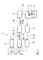
- Fig. 1 is an embodiment of a drive device 1 for controlling a hydraulic valve 2, which is part of a hydraulic circuit not shown in detail in a clutch drive of a motor vehicle transmission shown.
- the hydraulic valve 2 comprises a coil 3 and a mechanically movable closing element 4, which cooperate according to the electrodynamic plunger coil principle.
- the drive device 1 comprises a control loop with a regulator 5, an adder 6, a PWM generator 7, a MOSFET output stage designed as a driver 8, a current meter 9 and a low-pass filter 10. Between the controller 5 and the PWM generator arranged adder 6 is also connected to an overlay unit 11.
- the controller 5 has an input 12.
- the superimposition unit 11 has two inputs 13 and 14. The inputs 12 to 14 are for feeding setpoint values which originate from a higher-level control unit, not shown.
- the superimposition unit 11 is also connected to an output 15 of the regulator 5.
- the controller 5 contains, in addition to the input 12, a further input 16 to which a feedback branch of the control loop is connected.
- subunits of the control device 1 can be designed as physically separate (electronic) modules or as software modules that run on a computing unit (for example, a microprocessor) executed.
- a computing unit for example, a microprocessor
- a mixed form is also possible.
- the driver 8 and the ammeter 9 are separate electronic assemblies, whereas the remaining subunits are implemented as software modules in a computing unit, not shown.
- a flowing in the coil 3 current I causes a change in position of the closing element 4, so that the opening degree of the hydraulic valve 2 can be adjusted.
- the closing element 4 is set in a cyclical movement about an essentially constant or at least only comparatively slowly variable basic position.
- Both the basic position and the cyclic movement are effected by means of a drive signal S A , which is applied to the coil 3 and which is generated by the driver 8 on the basis of a pulse width modulated PWM signal S P.
- the drive signal S A and the PWM signal S P have substantially the same waveform.
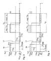
- the example in the lower diagram of Fig. 2 Plotted over the time t PWM signal S P has a PWM frequency f PWM whose reciprocal is a PWM period T PWM .
- T PWM Within the PWM period T PWM is switched to a switching time between a switch-on and a switch-off.
- a duty cycle results as a quotient of the duration of the switch-on phase to the PWM period T PWM .
- the duty cycle of the PWM signal S P generated by the PWM generator 7 is not constant. It varies cyclically and is adjusted depending on the instantaneous value of a pulse duty signal TV present at the input of the PWM generator 7. This relationship is in the two diagrams of Fig. 2 in the upper diagram an exemplary duty cycle signal TV and in the lower diagram a resulting PWM signal S P are shown.
- the duty cycle signal TV has a rectangular waveform, which varies with a superposition period T Ü by an average duty cycle TV M. It alternates between a low duty cycle value TV L and a high duty cycle value TV H.
- the duty cycle signal TV determines the respective duration of the switch-on phase of the PWM signal S P. Accordingly, the power-on phase lasts longer in the presence of the high duty cycle value TV H than in the presence of the low duty cycle value TV L.
- This variation of the duration of the switch-on phase in the PWM signal S P has no influence on the average value of the PWM signal S P and the electrical current I derived therefrom and the finally resulting movement of the closing element 4, since the variation cycles cyclically with the overlap period T Ü repeated.
- the duty cycle signal TV comprises a substantially constant or only very slowly time-varying basic component and a periodic component of the overlay. It is formed by adding a provided by the controller 5 at the output 15 basic signal S G and one generated by the superimposition unit 11 overlay signal S Ü in the adder 6.
- the superposition signal S Ü is also called a dither signal. It is determined in the superposition unit 11 on the basis of the values specified for the inputs 13 and 14 for a superposition current I Ü or for a superposition frequency f Ü corresponding to the reciprocal of the superimposed period T Ü . These specifications ultimately determine at which speed and with which amplitude the movement of the closing element 4 takes place.
- the specifications made at the inputs 13 and 14 depend on the type of hydraulic valve 2. In addition, these specifications can also be made taking into account further parameters, such as the ambient temperature.
- the superposition frequency f Ü is in the range between a few 10 Hz and a few 100 Hz. In the exemplary embodiment, 300 Hz are provided.
- the superposition period T Ü is, in particular, an integer multiple of the PWM period T PWM which is dependent on the type of the hydraulic valve 2.
- Their reciprocal, that is the PWM frequency f PWM is typically in the range of a few kHz. In the embodiment, 3 kHz are provided.
- the basic signal S G responsible for the basic position of the closing element 4 is derived from the nominal current I S present at the input 12.
- the quantity present at the input 16 results from a measurement of the electric current I by means of the current meter 9 and a filtering of this measured value M in the low-pass filter 10.
- the cut-off frequency of the low-pass filter 10 is low enough to complete the PWM frequency f PWM and the superposition frequency f Ü at least partially filter out of the measured value M. On the other hand, it is big enough not to influence the dynamics of the control loop too much.
- the drive signal S A causes an electrical current I in the coil 3, the time course of which due to the coil inertia is not identical to that of the PWM signal S P. But also the current I contains a substantially constant fundamental component and a with the superposition frequency f Ü periodically fluctuating superposition share. Due to the inertia of the closing element 4 and also due to the coil inertia, the mechanical adjustment movement of the closing element 4 of the comparatively high PWM frequency f PWM not follow. By contrast, the superposition frequency f Ü is low enough to cause a corresponding cyclical movement of the closing element 4, which counteracts the undesirable stick-slip effect.
- Fig. 2 symmetrical relationships are shown.
- the duty cycle signal TV has a symmetry.
- the high and the low duty cycle values TV H and TV L are respectively assumed during one half of the overlay period T Ü . This results in a superposition ratio ⁇ of 0.5, which is formed as a quotient of the duration of the high duty cycle value TV H and of the overlay period T Ü .
- a correction is provided with a change to an asymmetrical signal curve of the duty cycle signal TV. Examples of this are in the diagrams of 3 and 4 shown.
- a fictitious signal course 17 of the duty ratio signal TV resulting initially from the default values is shown in dashed lines, while solid lines are provided for corrected waveforms 18 and 19. In the examples shown, the fictitious waveform 17 each falls below the lower limit of zero.
- the correction is performed on the superposition signal S Ü in the superimposition unit 11.
- the superposition unit 11 is supplied with the basic signal S G currently present at the output 15 of the controller 5.
- these checking and correction performed in the overlay unit 11 in the exemplary embodiment can also take place elsewhere, for example in the adder 6 or in a subunit provided on the input side in the PWM generator 7.
- the absolute distance between the two duty cycle values TV L and TV H on the one hand and TV LK and TV HK on the other hand remains the same, so that the cyclical movement of the closing element 4 is still guaranteed to the same extent.
- the value for the corrected overlay ratio ⁇ K1 determined according to equation (4) generally does not fall within the grid of the PWM period T PWM .
- a raster conformity is deliberately set by selecting the period of time during which the corrected low or high duty cycle value TV LK or TV HK is assumed to be an integer multiple of the PWM period T PWM .
- the raster conformity is favorable because the drive device 1 can be realized thereby more simply.
- a raster conformity which is taken into account in the correction namely makes an otherwise possibly necessary adaptation of further parameters, such as the PWM period T PWM, superfluous.
- the corrected beat ratio ⁇ K1 indicates an upper limit to which the corrected low duty ratio value TV LK takes a value ⁇ 0.
- this yields the following condition for the integer n: n ⁇ TV M 2 ⁇ TV U ⁇ ⁇ T U ⁇ T PWM and n ⁇ 0 1 2 3 ... ,
Landscapes
- Engineering & Computer Science (AREA)
- General Engineering & Computer Science (AREA)
- Physics & Mathematics (AREA)
- Electromagnetism (AREA)
- Mechanical Engineering (AREA)
- Magnetically Actuated Valves (AREA)
Claims (12)
- Procédé de pilotage électrique d'une soupape (2) avec un élément de fermeture (4) mécanique, dans lequela) l'élément de fermeture (4) est déplacé au moyen d'un courant électrique (I) s'écoulant dans une bobine (3),b) le courant électrique (I) est produit au moyen d'un signal PWM à modulation de largeur d'impulsions (Sp) qui présente une durée de période PWM (TPWM) paramétrée et un taux d'impulsions,c) le taux d'impulsions est réglé au moyen d'un signal de taux d'impulsions (TV) qui se compose de façon additive d'une fraction de base (SG) et d'une fraction de superposition (SÜ) avec une durée de période de superposition (TÜ) à l'intérieur de laquelle le signal de taux d'impulsions (TV) est commuté entre une valeur de taux d'impulsions élevée et une valeur de taux d'impulsions faible (TVH, TVL; TVHK, TVLK),d) il est vérifié si l'addition de la fraction de base (SG) et de la fraction de superposition (SÜ) prévue initialement fournit une valeur de taux d'impulsions (TVL) faible fictive inférieure à zéro ou une valeur de taux d'impulsions (TVH) élevée fictive supérieure à un et, dans l'affirmative, une correction est effectuée, par le fait quela correction étant effectuée de sorte que la valeur moyenne temporelle arithmétique (TVM) du signal de taux d'impulsions (TV) n'est pas modifiée de façon importante.d1) la valeur de taux d'impulsions (TVL) faible est augmentée à au moins zéro, et la valeur de taux d'impulsions (TVH) élevée est augmentée à une valeur de taux d'impulsions (TVHK) élevée corrigée, ou la valeur de taux d'impulsions (TVH) élevée est abaissée à un au maximum et la valeur de taux d'impulsions (TVL) faible est abaissée à une valeur de taux d'impulsions (TVHK) faible corrigée, etd2) une durée de taux d'impulsions depuis le début de la durée de période de superposition (TÜ) jusqu'à la commutation entre les deux valeurs de taux d'impulsions corrigées (TVLK, TVHK) est réglée en tant que multiple entier de la durée de période PWM (TPWM),
- Procédé selon la revendication 1, caractérisé en ce que la fraction de base (SG) est déterminée par le fait qu'une valeur de mesure (M) du courant électrique (I) s'écoulant dans la bobine (3) est définie et est comparée, dans le cadre d'une régulation, avec une valeur de consigne (IS) paramétrable.
- Procédé selon la revendication 2, caractérisé en ce que la valeur de mesure (M) est soumise à un filtrage passe-bas.
- Procédé selon la revendication 1, caractérisé en ce que la durée de taux d'impulsions est réglée sur le multiple entier le plus grand possible de la durée de période PWM (TPWM).
- Procédé selon la revendication 1, caractérisé en ce que les valeurs de taux d'impulsions faible et élevée corrigées (TVLK, TVHK) sont réglées selon


si la vérification montre que la valeur de taux d'impulsions faible fictive est inférieure à zéro, TVM désignant la fraction de base, TVÜ l'amplitude de la fraction de superposition prévue initialement, TÜ la durée de période de superposition, TPWM la durée de période PWM et n un nombre naturel. - Procédé selon la revendication 5, caractérisé en ce que le nombre naturel n est réglé sur la plus grande valeur qui respecte les conditions

- Equipement de pilotage électrique d'une soupape (2) avec un élément de fermeture mécanique (4), comprenanta) un générateur PWM (7) pour la production d'un signal PWM à modulation de largeur d'impulsions (Sp) qui présente une durée de période PWM (TPWM) paramétrée et un taux d'impulsions, et sur la base duquel il se produit une alimentation d'un courant électrique (I) dans une bobine (3) coopérant avec l'élément de fermeture (4) et,b) sur le côté entrée, des moyens de fourniture (5, 6, 11), raccordés au générateur PWM (7), pour la fourniture d'un signal de taux d'impulsions (TV) définissant le taux d'impulsions,l'adaptation de valeurs des valeurs de taux d'impulsions (TVLK, TVHK) et le réglage de la durée de taux d'impulsions ne modifiant pas de façon importante la valeur moyenne (TVM) temporelle arithmétique du signal de taux d'impulsions (TV).b1) les moyens de fourniture (5, 6, 11) comprenant un circuit d'addition (6) pour produire le signal de taux d'impulsions (TV) à partir d'une fraction de base (SG) et d'une fraction de superposition (SÜ) avec une durée de période de superposition (TÜ) à l'intérieur de laquelle le signal de taux d'impulsions (TV) varie entre une valeur de taux d'impulsions élevée et une valeur de taux d'impulsions faible (TVH, TVL ;TVHK,TVLK),b2) les moyens de fourniture (5, 6, 11) contenant des moyens de correction (11) qui sont calculésb21) pour vérifier si l'addition de la fraction de base (SG) et de la fraction de superposition (SÜ) prévue initialement fournit une valeur de taux d'impulsions (TVL) faible fictive inférieure à zéro ou une valeur de taux d'impulsions (TVH) élevée fictive supérieure à un,b22) pour adapter les valeurs au moyen du relèvement de la valeur de taux d'impulsions (TVL) faible à au moins zéro et de la valeur de taux d'impulsions (TVH) élevée à une valeur de taux d'impulsions (TVHK) élevée corrigée, ou pour adapter les valeurs au moyen de l'abaissement de la valeur de taux d'impulsions (TVH) élevée à un au maximum et de la valeur de taux d'impulsions (TVL) faible à une valeur de taux d'impulsions (TVLK) faible corrigée, etb23) pour régler une durée de taux d'impulsions depuis le début de la durée de période de superposition (TÜ) jusqu'à la commutation entre les deux valeurs de taux d'impulsions (TVLK, TVHK) corrigées en tant que multiple entier de la durée de période PWM (TPWM),
- Equipement selon la revendication 7, caractérisé en ce que les moyens de fourniture (5, 6, 11) contiennent une régulateur (5) pour la comparaison d'une valeur de mesure (M) du courant électrique (I) s'écoulant dans la bobine (3) avec une valeur de consigne (IS) paramétrable.
- Equipement selon la revendication 8, caractérisé en ce qu'il est prévu un filtre passe-bas (10) pour le filtrage de la valeur de mesure (M).
- Equipement selon la revendication 7, caractérisé en ce que les moyens de correction (11) sont calculés pour le réglage de la durée de taux d'impulsions sur le multiple entier le plus grand possible de la durée de période PWM (TPWM).
- Equipement selon la revendication 7, caractérisé en ce que les moyens de correction (11) sont calculés pour le réglage des valeurs de taux d'impulsions (TVLK, TVHK) faible et élevée corrigées selon


dans le cas où la vérification indique que la valeur de taux d'impulsions faible fictive est inférieure à zéro, TVM désignant la fraction de base, TVÜ l'amplitude de la fraction de superposition prévue initialement, TÜ la durée de période de superposition, TPWM la durée de période PWM et n un nombre naturel. - Equipement selon la revendication 11, caractérisé en ce que les moyens de correction (11) sont calculés pour le réglage du nombre naturel n à la plus grande valeur qui respecte les conditions

Applications Claiming Priority (2)
| Application Number | Priority Date | Filing Date | Title |
|---|---|---|---|
| DE200510022063 DE102005022063A1 (de) | 2005-05-12 | 2005-05-12 | Verfahren und Einrichtung zur elektrischen Ansteuerung eines Ventils mit einem mechanischen Schließelement |
| PCT/DE2006/000814 WO2006119751A2 (fr) | 2005-05-12 | 2006-05-12 | Procede et dispositif de commande electrique d'une soupape au moyen d'un element de fermeture mecanique |
Publications (2)
| Publication Number | Publication Date |
|---|---|
| EP1880096A2 EP1880096A2 (fr) | 2008-01-23 |
| EP1880096B1 true EP1880096B1 (fr) | 2009-10-28 |
Family
ID=37075808
Family Applications (1)
| Application Number | Title | Priority Date | Filing Date |
|---|---|---|---|
| EP06742322A Active EP1880096B1 (fr) | 2005-05-12 | 2006-05-12 | Procede et dispositif de commande electrique d'une soupape au moyen d'un element de fermeture mecanique |
Country Status (4)
| Country | Link |
|---|---|
| EP (1) | EP1880096B1 (fr) |
| CN (1) | CN101166895B (fr) |
| DE (3) | DE102005022063A1 (fr) |
| WO (1) | WO2006119751A2 (fr) |
Families Citing this family (8)
| Publication number | Priority date | Publication date | Assignee | Title |
|---|---|---|---|---|
| DE102006045353A1 (de) * | 2006-09-26 | 2008-04-03 | Lucas Automotive Gmbh | Regeleinheit und Verfahren zur Regelung einer elektromagnetischen Ventilanordnung |
| DE102008031906B4 (de) * | 2008-07-08 | 2015-03-19 | Ifm Electronic Gmbh | Steuergerät und Verfahren zum Betreiben eines Steuergeräts |
| KR102052954B1 (ko) * | 2012-11-05 | 2019-12-06 | 콘티넨탈 오토모티브 시스템 주식회사 | 솔레노이드 과통전을 방지하기 위한 솔레노이드 제어 장치 및 방법 |
| CN103513571A (zh) * | 2013-09-18 | 2014-01-15 | 东莞博用电子科技有限公司 | 一种带限幅的脉宽调制装置和方法 |
| US9920856B2 (en) | 2014-03-31 | 2018-03-20 | Dresser, Inc. | Method for determining amplitude of stick-slip on a valve assembly and implementation thereof |
| DE102014206973A1 (de) * | 2014-04-10 | 2015-10-15 | Volkswagen Aktiengesellschaft | Verfahren zur Steuerung eines Elektromagnetventils |
| DE102016215229A1 (de) * | 2016-08-16 | 2018-02-22 | Zf Friedrichshafen Ag | Verfahren zum Betätigen einer Ventileinrichtung in Abhängigkeit einer Kennlinie |
| KR101896324B1 (ko) * | 2016-09-19 | 2018-09-07 | 현대자동차 주식회사 | 연료 증기 퍼지 장치 및 방법 |
Family Cites Families (12)
| Publication number | Priority date | Publication date | Assignee | Title |
|---|---|---|---|---|
| KR960007409B1 (ko) * | 1994-04-01 | 1996-05-31 | 아시아자동차공업주식회사 | 자동차용 전자식 액세레이터 페달 제어장치 |
| DE4429373A1 (de) * | 1994-08-22 | 1996-02-29 | Bosch Gmbh Robert | Einrichtung zur Ansteuerung eines Verbrauchers |
| DE19544517C2 (de) * | 1995-11-29 | 1999-08-05 | Siemens Ag | Steuereinrichtung für ein automatisches Kraftfahrzeuggetriebe |
| DE19727358B4 (de) * | 1996-07-02 | 2008-02-07 | Conti Temic Microelectronic Gmbh | Druckmittelanlage sowie ein Verfahren zu deren Verwendung |
| JP3855209B2 (ja) * | 1996-12-09 | 2006-12-06 | 株式会社日立製作所 | サスペンション制御装置 |
| JP3687020B2 (ja) * | 1997-03-18 | 2005-08-24 | 株式会社日立製作所 | Pwm式比例ソレノイドバルブ制御装置 |
| DE19930965A1 (de) * | 1999-07-05 | 2001-01-11 | Mannesmann Sachs Ag | Verfahren zum Betätigen eines Stromreglers für ein Stellglied sowie Stromregler |
| DE19944831A1 (de) * | 1999-09-18 | 2001-03-22 | Bosch Gmbh Robert | Verfahren und Vorrichtung zur Steuerung eines Verbrauchers |
| DE19949684A1 (de) * | 1999-10-15 | 2001-02-08 | Daimler Chrysler Ag | Verfahren zur Vorgabe des Stroms durch ein induktives Bauteil |
| DE19963154B4 (de) * | 1999-12-24 | 2009-10-08 | Conti Temic Microelectronic Gmbh | Verfahren zur Vorgabe des Stroms durch ein induktives Bauteil |
| DE19963153B4 (de) * | 1999-12-24 | 2005-01-05 | Conti Temic Microelectronic Gmbh | Verfahren zum Betrieb eines Systems |
| DE10160477A1 (de) * | 2001-12-08 | 2003-06-18 | Ballard Power Systems | Verfahren zur Steuerung eines Stellglieds |
-
2005
- 2005-05-12 DE DE200510022063 patent/DE102005022063A1/de not_active Withdrawn
-
2006
- 2006-05-12 WO PCT/DE2006/000814 patent/WO2006119751A2/fr not_active Application Discontinuation
- 2006-05-12 DE DE112006000656T patent/DE112006000656A5/de not_active Withdrawn
- 2006-05-12 CN CN2006800136734A patent/CN101166895B/zh not_active Expired - Fee Related
- 2006-05-12 DE DE502006005250T patent/DE502006005250D1/de active Active
- 2006-05-12 EP EP06742322A patent/EP1880096B1/fr active Active
Also Published As
| Publication number | Publication date |
|---|---|
| DE102005022063A1 (de) | 2006-11-16 |
| CN101166895A (zh) | 2008-04-23 |
| WO2006119751A2 (fr) | 2006-11-16 |
| CN101166895B (zh) | 2010-06-16 |
| DE112006000656A5 (de) | 2008-01-03 |
| EP1880096A2 (fr) | 2008-01-23 |
| DE502006005250D1 (de) | 2009-12-10 |
| WO2006119751A3 (fr) | 2007-02-08 |
Similar Documents
| Publication | Publication Date | Title |
|---|---|---|
| EP1880096B1 (fr) | Procede et dispositif de commande electrique d'une soupape au moyen d'un element de fermeture mecanique | |
| EP2891161B1 (fr) | Procédé de régulation de l'intensité du courant électrique circulant dans une charge inductive, et circuit correspondant | |
| DE2751743A1 (de) | Verfahren und regeleinrichtung zum zumessen stroemender medien | |
| EP2850725B1 (fr) | Procédé de régulation d'une source de courant, source de courant et régulateur de processus associés | |
| EP1703629B1 (fr) | Procédé pour la commande digitale de courant | |
| EP1540431B1 (fr) | Procede de regulation du courant traversant un element d'ajustement electromagnetique | |
| DE3343883A1 (de) | Verfahren und einrichtung zur zweipunktregelung eines laststromes | |
| EP3605832A1 (fr) | Courant de maintien adaptatif pour moteurs électriques à commutation électrique | |
| DE19930965A1 (de) | Verfahren zum Betätigen eines Stromreglers für ein Stellglied sowie Stromregler | |
| WO1999027640A2 (fr) | Procede et circuit pour la production d'un signal de reglage a modulation d'impulsions en largeur pour un actionneur a courant continu | |
| EP2371055B1 (fr) | Procédé et dispositif d'excitation d'un moteur électrique | |
| DE102013107792A1 (de) | Steuergerät für einen wandler und steuerverfahren | |
| DE3610500A1 (de) | Vorrichtung und verfahren zum regeln des stroms in einer induktiven last | |
| EP2383879A2 (fr) | Procédé et dispositif de synchronisation pour la synchronisation d'au moins deux entraînements d'aspiration de fumée et de chaleur et à clapets d'aération | |
| DE102014103027A1 (de) | Nachführregler für eine U/f-gesteuerte Asynchronmaschine | |
| EP1146405B1 (fr) | Méthode de régulation | |
| DE19651062C2 (de) | System zur Regelung der Position eines Motors gegen eine Rückstellkraft | |
| DE4203191C2 (de) | Einrichtung zur Positionierung einer Verstelleinrichtung in einem Fahrzeug | |
| DE10301501B4 (de) | Schaltungsanordnung und Verfahren zur Erzeugung eines Pulsweiten-modulierten Signals | |
| WO2010118978A2 (fr) | Procédé pour utiliser un circuit de commande, en particulier pour une application sur un véhicule automobile | |
| DE2626831B2 (de) | Nutzbrems-regelanordnung fuer gleichstrommotoren | |
| DE102021206426B3 (de) | Regeleinrichtung zur Regelung einer eine Brennkraftmaschine und einen mit der Brennkraftmaschine antriebswirkverbundenen Generator umfassenden Leistungsanordnung, Regelanordnung mit einer solchen Regeleinrichtung, Leistungsanordnung und Verfahren zur Regelung einer Leistungsanordnung | |
| DE102007062173A1 (de) | Verfahren zum Betreiben einer Brennkraftmaschine und Steuer- oder Regelrichtung für eine Brennkraftmaschine | |
| DE19817891A1 (de) | Verfahren und Schaltungsanordnung zur Erzeugung eines pulsbreitenmodulierten Stellsignals für einen Gleichstrom-Aktuator | |
| WO2022117246A1 (fr) | Dispositif de commande pour convertisseur continu-continu, convertisseur continu-continu et procédé d'actionnement d'un convertisseur continu-continu |
Legal Events
| Date | Code | Title | Description |
|---|---|---|---|
| PUAI | Public reference made under article 153(3) epc to a published international application that has entered the european phase |
Free format text: ORIGINAL CODE: 0009012 |
|
| 17P | Request for examination filed |
Effective date: 20070925 |
|
| AK | Designated contracting states |
Kind code of ref document: A2 Designated state(s): DE FR |
|
| DAX | Request for extension of the european patent (deleted) | ||
| RBV | Designated contracting states (corrected) |
Designated state(s): DE FR |
|
| GRAP | Despatch of communication of intention to grant a patent |
Free format text: ORIGINAL CODE: EPIDOSNIGR1 |
|
| GRAS | Grant fee paid |
Free format text: ORIGINAL CODE: EPIDOSNIGR3 |
|
| GRAA | (expected) grant |
Free format text: ORIGINAL CODE: 0009210 |
|
| AK | Designated contracting states |
Kind code of ref document: B1 Designated state(s): DE FR |
|
| REF | Corresponds to: |
Ref document number: 502006005250 Country of ref document: DE Date of ref document: 20091210 Kind code of ref document: P |
|
| PLBE | No opposition filed within time limit |
Free format text: ORIGINAL CODE: 0009261 |
|
| STAA | Information on the status of an ep patent application or granted ep patent |
Free format text: STATUS: NO OPPOSITION FILED WITHIN TIME LIMIT |
|
| 26N | No opposition filed |
Effective date: 20100729 |
|
| REG | Reference to a national code |
Ref country code: FR Ref legal event code: PLFP Year of fee payment: 11 |
|
| REG | Reference to a national code |
Ref country code: FR Ref legal event code: PLFP Year of fee payment: 12 |
|
| REG | Reference to a national code |
Ref country code: FR Ref legal event code: PLFP Year of fee payment: 13 |
|
| REG | Reference to a national code |
Ref country code: DE Ref legal event code: R084 Ref document number: 502006005250 Country of ref document: DE |
|
| REG | Reference to a national code |
Ref country code: DE Ref legal event code: R081 Ref document number: 502006005250 Country of ref document: DE Owner name: VITESCO TECHNOLOGIES GERMANY GMBH, DE Free format text: FORMER OWNER: CONTI TEMIC MICROELECTRONIC GMBH, 90411 NUERNBERG, DE |
|
| PGFP | Annual fee paid to national office [announced via postgrant information from national office to epo] |
Ref country code: FR Payment date: 20210520 Year of fee payment: 16 |
|
| REG | Reference to a national code |
Ref country code: DE Ref legal event code: R081 Ref document number: 502006005250 Country of ref document: DE Owner name: VITESCO TECHNOLOGIES GERMANY GMBH, DE Free format text: FORMER OWNER: VITESCO TECHNOLOGIES GERMANY GMBH, 30165 HANNOVER, DE |
|
| PG25 | Lapsed in a contracting state [announced via postgrant information from national office to epo] |
Ref country code: FR Free format text: LAPSE BECAUSE OF NON-PAYMENT OF DUE FEES Effective date: 20220531 |
|
| P01 | Opt-out of the competence of the unified patent court (upc) registered |
Effective date: 20230530 |
|
| PGFP | Annual fee paid to national office [announced via postgrant information from national office to epo] |
Ref country code: DE Payment date: 20230531 Year of fee payment: 18 |