EP1879781B1 - Lenkvorrichtung, insbesondere für eine hinterradlenkung - Google Patents
Lenkvorrichtung, insbesondere für eine hinterradlenkung Download PDFInfo
- Publication number
- EP1879781B1 EP1879781B1 EP06754924A EP06754924A EP1879781B1 EP 1879781 B1 EP1879781 B1 EP 1879781B1 EP 06754924 A EP06754924 A EP 06754924A EP 06754924 A EP06754924 A EP 06754924A EP 1879781 B1 EP1879781 B1 EP 1879781B1
- Authority
- EP
- European Patent Office
- Prior art keywords
- wheel
- steering mechanism
- mechanism according
- nut
- coupling element
- Prior art date
- Legal status (The legal status is an assumption and is not a legal conclusion. Google has not performed a legal analysis and makes no representation as to the accuracy of the status listed.)
- Active
Links
- 239000000725 suspension Substances 0.000 claims abstract description 13
- 230000008878 coupling Effects 0.000 claims description 28
- 238000010168 coupling process Methods 0.000 claims description 28
- 238000005859 coupling reaction Methods 0.000 claims description 28
- 230000033001 locomotion Effects 0.000 claims description 16
- 230000005540 biological transmission Effects 0.000 claims description 13
- 230000006835 compression Effects 0.000 claims description 7
- 238000007906 compression Methods 0.000 claims description 7
- 238000006073 displacement reaction Methods 0.000 claims description 5
- 230000009467 reduction Effects 0.000 claims description 5
- 230000008859 change Effects 0.000 description 10
- 230000000903 blocking effect Effects 0.000 description 7
- 239000000969 carrier Substances 0.000 description 5
- 238000011161 development Methods 0.000 description 4
- 230000018109 developmental process Effects 0.000 description 4
- 238000000034 method Methods 0.000 description 4
- 238000013461 design Methods 0.000 description 3
- 238000013519 translation Methods 0.000 description 3
- 230000001133 acceleration Effects 0.000 description 2
- 230000008901 benefit Effects 0.000 description 2
- 230000004048 modification Effects 0.000 description 2
- 238000012986 modification Methods 0.000 description 2
- 230000008054 signal transmission Effects 0.000 description 2
- 230000008093 supporting effect Effects 0.000 description 2
- 230000007423 decrease Effects 0.000 description 1
- 230000001419 dependent effect Effects 0.000 description 1
- 238000005516 engineering process Methods 0.000 description 1
- 230000002349 favourable effect Effects 0.000 description 1
- 238000009434 installation Methods 0.000 description 1
Images

Classifications
-
- B—PERFORMING OPERATIONS; TRANSPORTING
- B62—LAND VEHICLES FOR TRAVELLING OTHERWISE THAN ON RAILS
- B62D—MOTOR VEHICLES; TRAILERS
- B62D7/00—Steering linkage; Stub axles or their mountings
- B62D7/06—Steering linkage; Stub axles or their mountings for individually-pivoted wheels, e.g. on king-pins
- B62D7/14—Steering linkage; Stub axles or their mountings for individually-pivoted wheels, e.g. on king-pins the pivotal axes being situated in more than one plane transverse to the longitudinal centre line of the vehicle, e.g. all-wheel steering
-
- B—PERFORMING OPERATIONS; TRANSPORTING
- B60—VEHICLES IN GENERAL
- B60G—VEHICLE SUSPENSION ARRANGEMENTS
- B60G7/00—Pivoted suspension arms; Accessories thereof
- B60G7/001—Suspension arms, e.g. constructional features
- B60G7/003—Suspension arms, e.g. constructional features of adjustable length
-
- B—PERFORMING OPERATIONS; TRANSPORTING
- B62—LAND VEHICLES FOR TRAVELLING OTHERWISE THAN ON RAILS
- B62D—MOTOR VEHICLES; TRAILERS
- B62D7/00—Steering linkage; Stub axles or their mountings
- B62D7/06—Steering linkage; Stub axles or their mountings for individually-pivoted wheels, e.g. on king-pins
- B62D7/14—Steering linkage; Stub axles or their mountings for individually-pivoted wheels, e.g. on king-pins the pivotal axes being situated in more than one plane transverse to the longitudinal centre line of the vehicle, e.g. all-wheel steering
- B62D7/146—Steering linkage; Stub axles or their mountings for individually-pivoted wheels, e.g. on king-pins the pivotal axes being situated in more than one plane transverse to the longitudinal centre line of the vehicle, e.g. all-wheel steering characterised by comprising means for steering by acting on the suspension system, e.g. on the mountings of the suspension arms
-
- B—PERFORMING OPERATIONS; TRANSPORTING
- B62—LAND VEHICLES FOR TRAVELLING OTHERWISE THAN ON RAILS
- B62D—MOTOR VEHICLES; TRAILERS
- B62D7/00—Steering linkage; Stub axles or their mountings
- B62D7/20—Links, e.g. track rods
-
- B—PERFORMING OPERATIONS; TRANSPORTING
- B60—VEHICLES IN GENERAL
- B60G—VEHICLE SUSPENSION ARRANGEMENTS
- B60G2202/00—Indexing codes relating to the type of spring, damper or actuator
- B60G2202/40—Type of actuator
- B60G2202/42—Electric actuator
-
- B—PERFORMING OPERATIONS; TRANSPORTING
- B60—VEHICLES IN GENERAL
- B60G—VEHICLE SUSPENSION ARRANGEMENTS
- B60G2204/00—Indexing codes related to suspensions per se or to auxiliary parts
- B60G2204/40—Auxiliary suspension parts; Adjustment of suspensions
- B60G2204/419—Gears
Definitions
- the invention relates to a steering device for adjusting a Radeinschlagswinkels a wheel of a motor vehicle, in particular a rear wheel, comprising at least one Rad arrangementsglied, via which a wheel of the wheel is connected to a vehicle body, wherein the wheel carrier is pivotable about a substantially parallel to the wheel plane axis of rotation and the wheel guide is spaced from the axis of rotation of the wheel carrier is articulated, and wherein the wheel guide member is adjustable by means of a drive unit in its length.
- a steering device of the type mentioned is known.
- a device for detecting the vehicle speed and other values is provided, wherein the control of the steering device is based on the vehicle speed and the other values.
- this object is achieved by a steering device with the features of claim 1.
- the drive unit comprises a blocking device, in which at least one magnetic plunger by switching off an electromagnet form-fitting can be inserted into a receptacle of a nut or a coupling element, whereby the drive unit can be blocked.
- a wheel guide member of a conventional suspension is replaced by a length-adjustable wheel guide.
- a change in length of the wheel guide leads to a change in the Radeinschlagswinkels the wheel.
- the suspension does not need to be changed and the steering device can be easily integrated into a conventional suspension.
- the axis of rotation of the achievable pivotal movement of the wheels is usually not completely parallel to the wheel plane, in particular due to the fall of the wheels.
- the deviation corresponds to the camber angle of the wheels.
- the wheel guide member is embodied in one piece and is articulated to the vehicle body via a first joint and to the wheel carrier via a second joint.
- single-limbed is understood to mean that the wheel guide element otherwise has no pivot joints. It is thus rigid in itself, as is usually the case with the wheel guide members of conventional suspension.
- the wheel guide element is a track rod and / or a transverse link of an independent wheel suspension.
- the wheel guide member comprises a housing and a push rod, which are axially displaceable against each other by means of an electromechanical drive unit.
- this embodiment is preferred because it can be dispensed with a pressure supply device.
- a likewise preferred embodiment of the invention is characterized in that the drive unit is contained in the housing.
- An advantageous embodiment of the invention includes that the drive unit includes an electric motor and a driven by the electric motor threaded spindle nut drive, which has a nut which engages in a spindle portion of the push rod.
- threaded spindle nut drive is a ball screw drive.
- a particularly preferred embodiment of the invention provides that the push rod is supported by means of a compensation spring on the housing.
- the spring force of the compensation spring counteracts a reduction in length of the wheel guide member and thus supports the pressure forces acting.
- a drive shaft of the electric motor is connected via a gear with the mother of the threaded spindle nut drive.
- An advantageous development of the invention is characterized in that the gear and / or the threaded spindle nut drive has the blocking device.
- the drive unit can be blocked when the motor is not energized in order to prevent an unwanted change in length of the wheel guide element or an unwanted steering movement of the wheel.
- An advantageous embodiment of the invention includes that a clamping ring is fixedly connected to an inner wall of the housing and the transmission comprises a rotatably mounted in the outer region of the clamping ring coupling element, wherein the coupling element with the nut of the threaded nut nut drive, in the interior of the clamping ring is rotatably mounted, is engaged.
- a plurality of receptacles for the magnetic plunger are regularly spaced on the circumference of the nut and / or the coupling element are arranged.
- the mother of the threaded spindle nut drive can be advantageous block in a plurality of regularly spaced angular positions by means of the magnetic plunger.
- An advantageous development of the invention is characterized in that the transmission has a freewheel device, which causes in a first torque range, a freewheel of the nut of the threaded spindle drive and in a second torque range, a blockage of the nut.
- the freewheel device comprises two clamping body, which are held within a driven by the electric motor freewheel cage between the clamping ring and the coupling element, wherein an engagement pin of the freewheel cage engages with an opening of the coupling element with play and the Clamping means are pressed by means engaging on the engagement pin and aligned in the circumferential direction of the freewheel cage compression springs in wedge-shaped pockets of the coupling element and can be brought through recesses connected to the freewheel cage Freistellelements through the clamping ring in contact.
- the freewheel device When the clamping elements are in contact with the clamping ring, the freewheel device is in the blocking position. On the suspension acting disturbing forces that are transmitted via the threaded spindle nut drive on the coupling element are derived in the locked position in the clamping ring and do not lead to an unwanted change in length of the wheel guide.
- the clamping body are pressed in a rotational movement of the freewheel cage due to movement of the engagement pin in the opening of the coupling element from the recesses of the Freistellelements and lose contact with the clamping ring.
- the freewheel device enters the freewheeling position, which allows a motor-driven change in length of the wheel guide member.
- the relative position of the push rod with respect to the housing by means of a non-contact displacement sensor can be detected.
- the invention also provides a motor vehicle that includes a right and a left rear wheel, and is characterized in that each of two rear wheels is associated with a steering device of the type previously described.
- a particularly advantageous embodiment of the invention includes that the length-adjustable wheel guide of the right Rear wheel is adjustable independently of the length-adjustable wheel guide of the left rear wheel in its length.
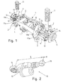
- FIG. 1 shows a rear axle integral carrier for a driven rear axle of a motor vehicle, as it is known per se from the prior art. It has a subframe 1, which at attachment points 2 with an in FIG. 1 not shown body of the vehicle is connected. Wheel carrier 3 are articulated via Rad arrangementslenker 4 connected to the subframe 1. Furthermore, a respective strut 5 is fixedly mounted on the wheel carriers 3 for support on the body. In FIG. 1 Wheel bearings 6 mounted on the wheel carriers are also shown. The rear wheels of the vehicle which can be mounted on the wheel carriers 3 and the wheel bearings 6 are each driven by a wheel drive shaft 9. The wheel drive shafts 9 are connected to each other via a differential gear 10, which has a forwardly directed in the vehicle longitudinal direction flange 11 for flanging a driven by the vehicle engine shaft.
- a differential gear 10 which has a forwardly directed in the vehicle longitudinal direction flange 11 for flanging a driven by the vehicle engine shaft.
- a tie rod 12 with a fixed length which is connected by a respective pivot bearing 13, 14 with the subframe 1 on the one hand and the wheel carrier 3 on the other.
- the invention provides to replace a length-fixed wheel guide on each side of the rear axle integral carrier by a Rad Operationsglied which is adjustable in its length.
- the tie rods 12 each by a in FIG. 2 replace shown tie rod 15 which is variable in length L.
- the tie rod 15 has for attachment to the subframe 1 a bearing means web 16 which, together with the bearing side webs 17a, 17b (FIG. FIG. 1 ) of the subframe 1 forms the pivot bearing 13.
- the tie rod 17 can be hinged to the wheel carrier 3.
- the bearing center web 16 is attached to a housing 19 which contains a motor with which a push rod 51 can be moved distally and proximally via a transmission in order to lengthen or shorten the tie rod 15. At the push rod while the wheel carrier side joint 18 is arranged.
- a modification of the remaining Rad arrangementslenker 4 is usually not required, as suspensions usually allow pivoting of the wheels in the direction of toe and toe. Without further modifications, it is possible in particular to realize wheel steering angles which are in the range of the wheel steering angle due to elastokinematic steering movement and are already sufficiently large for an effective influencing of the vehicle dynamics. Likewise, however, it may also be provided to modify the suspension so that larger steering angles are possible.
- FIG. 3 shows a schematic representation of a four-wheeled motor vehicle with a left rear wheel 31a and a right rear wheel 31b.
- the rear wheels 31a, 31b are fastened to the vehicle by a rear axle carrier 32, which may be, for example, the one shown in FIG FIG. 1 can act Schuachsintegral (2004) shown.
- Each rear wheel 31a, 31b is associated with a tie rod 15a and 15b, each of which is a track rod 15 adjustable in its length.
- the tie rods engage via the lever 33a, 33b shown schematically in the figure to the rear wheels 31a, 31b, so that they can pivot due to changes in length of the tie rods 15a, 15b with respect to a pivot axis 34a, 34b by an angle.
- the control of the tie rods is carried out by a Häachslenkungs Kunststoff réelle 35, with which the tie rods 15a, 15b are each connected via an electronic interface.
- the Hinterachslenkungs Kunststoff réelle 35 is powered by the 12-volt supply voltage of the electrical system of the vehicle.
- control commands for controlling the motor of the tie rods 15a, 15b on the one hand and on the other hand signals from displacement sensors which detect the position of the push rod within the housing of the tie rod can be transmitted via the interface.
- the current wheel steering angle of the rear wheels 31a, 31b can be determined from these signals.
- the two tie rods 15a, 15b thereby represent independent modules that can be controlled independently of each other, so that in principle a freely selectable Radeinschlagwinkel can be set on each rear wheel 31a, 31b.
- the control is based on a control method in dependence on different vehicle sizes, which are measured in particular by means of sensors.
- the sensor technology of a vehicle dynamics control system for example an ESP system (ESP: Electronic Stability Program), is preferably used for carrying out the control method.
- ESP Electronic Stability Program
- the ESP controller is typically integrated with an electro-hydraulic unit for performing brake interventions in an assembly 42.
- the master cylinder 43 of the hydraulic vehicle brake system is connected to the wheel brakes 44a, 44b, 44c, 44d via the electrohydraulic unit.
- the brake pressure built up by the driver via the brake booster 45 by means of a brake actuating device 46 can be modified in a wheel-individual manner.
- the hydraulic unit has a pressure build-up device with which driver-independent brake interventions can be made to stabilize the vehicle, which are controlled by the ESP control unit on the basis of a control method known to a person skilled in the art.
- an interface for signal transmission between the ESP control unit and the Schuachslenkungs Kunststoff réelle 35 is provided.
- the signal transmission can take place, for example, via a data bus system such as the CAN (Controller Area Network) usually used in motor vehicles.
- CAN Controller Area Network
- the interface can be used to transmit the signals of the ESP sensor system to the rear axle steering control unit 35, which generates setpoint specifications for the wheel steering angle of the rear wheels 31a, 31b or the lengths of the tie rods 15a, 15b as a function of the sensor signals using a control method.
- setpoint specifications are determined in the ESP control unit and transmitted via the interface to the Schuachslenkungs Kunststoff réelle 35, which then controls the tie rods 15a, 15b according to the setpoint specifications.
- the rear wheels 31a, 31b can be deflected in the same direction or in opposite directions with respect to the steering movement of the front wheels 38a, 38b.
- the radius of curvature decreases at the same steering angle at the front wheels 38a, 38b, so that an increase in the agility of the vehicle can be achieved.
- the rear wheels 31a, 31b are turned in the opposite direction of rotation to the front wheels, the yaw rate of the vehicle is reduced, so that the vehicle can be stabilized in critical driving situations.
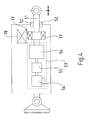
- FIG. 4 shows a schematic representation of the structure of the tie rod 15 in a preferred embodiment of the invention.
- the bearing means web 16 is fixedly mounted to the housing 19.
- the hinge 18 is attached to the distal end of the push rod 51 which is slidable within the housing and guided by thrust bearings 52 becomes.
- the tie rod 15 includes an electromechanical drive assembly 53. This includes an electric motor 54 whose motor shaft is coupled via a transmission gear 55 with a rotation / translation gear 56, which converts the rotational movement of the motor shaft in a translational movement of the push rod 51 and preferably is designed as a screw drive. Depending on the direction of rotation of the motor shaft, the push rod 51 is moved in the distal or proximal direction.
- the drive unit 53 also has a blocking device, which is designed such that the push rod 51 is displaceable exclusively by means of the electric motor 54 within the housing 19.
- the transmission gear 55 and / or the rotation / translation gear 56 has a self-locking, which causes such blocking. Further embodiments of the blocking device are described below in connection with FIGS Figure 5 to 7 described.
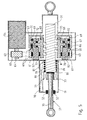
- FIG. 5 shows a schematic cross section through a tie rod 15 according to the invention in an advantageous embodiment, in which the rotation / translation gear 56 is formed as a ball screw (KGT).
- the electric motor 54 drives via the transmission gear 55, an annular freewheel cage 60, which is rotatably supported by means of an axial / radial bearing 61 on the outer circumference of a clamping ring 62.
- the clamping ring 62 is fixedly connected at one end face to the housing 19 of the tie rod 15.
- the transmission gear 55 is in the in FIG. 5 illustrated embodiment designed as a belt transmission, in which a belt 63, the rotational movement of an attached to the motor shaft 64 pulley 65 transmits to the freewheel cage 60.
- the transmission gear can also be designed as a gear or spur gear.
- the freewheel cage 60 drives via the freewheel device 66, which will be described in more detail later, a coupling element 67, which is in engagement with the nut 68 of the KGT.
- the coupling element 67 is also rotatably mounted on the outer circumference of the clamping ring 62 by means of an axial / radial bearing 69.
- the nut 68 engages over a number of balls 70 in a spindle portion 71 of the push rod 51 a.
- the nut 68 is supported by means of a thrust bearing 72 and a radial bearing 73.
- the spindle section 71 connects at its wheel carrier end to a further section 75 of the push rod 51.
- the push rod 51 is fixed by linear guides 52, which are arranged on a wheel carrier-side outlet opening of the housing 19.
- the linear guide 52 secures the push rod 51 thereby also with respect to a rotation.
- the push rod 51 is supported by means of a compensation spring 79 which is arranged between a first, attached to the push rod 51 pressure ring 80 and a second, on which the drive unit housing housing part mounted pressure ring 81.
- a compensation spring 79 pressure forces acting in the loaded state of the motor vehicle in the direction of the subframe 1 on the tie rod 15 are at least partially supported. If this did not happen, then an offset moment to overcome these pressure forces would have to be provided by the drive motor 54 with an increase in the length of the tie rod 15. With a reduction in length, the pressure forces would have a supporting effect, so that a much lower engine torque would be required. The motor operation would thus be asymmetrical with respect to the direction of rotation. However, this is prevented by the compensation spring 79, which ensures a symmetrical and energetically meaningful motor operation.
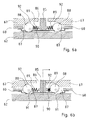
- the freewheel device 66 is shown in greater detail.
- the freewheel cage 60 is guided between the clamping ring 62 and the coupling element 67. He has at least one point on its circumference on a radially aligned engagement pin 85 which engages in a likewise radially aligned opening 86 of the coupling element 67.
- the cross-sectional area of the opening 86 is greater than the cross-sectional area of the engagement pin 85, so that a game arises.
- recesses 87 In the circumferential direction of the freewheel cage 60 are located next to the engagement pin 85 recesses 87, in which spherical clamping body 88 are introduced, which in each case by a compression spring 89 to the outside (i.e., in the direction away from the engagement pin 85) are pressed.
- the recesses 87 are delimited by a release element 90, which in turn has recesses 91 which have a smaller diameter than the clamping bodies 88 and are preferably trough-shaped in the edge region.
- the recesses 91 are in particular dimensioned such that the clamping bodies 88 located in the recesses 91 can be brought into contact with the clamping ring 62.
- the clamping bodies 88 engage in pockets 92 aligned in the circumferential direction of the coupling element 67 and wedge-shaped at least in sections, tapering outwards (i.e., in the direction away from the opening 86).
- the recesses 91 of the free-setting element 90 are arranged so that a free space remains between a clamping body 88 located in a recess 91 and the outer edge of the recess 87 of the free-wheeling cage 60.
- the compression springs 89 By means of the compression springs 89, the clamping body 88 are pressed against the clamping ramps of the pockets 92, whereby the freewheel cage 60 is fixed, as shown in the FIG. 6a is shown.
- the compression springs 89 are dimensioned so that small torques caused by disturbing forces acting on the rear wheel connected to the tie rod 15, the clamping body 88 does not drive out of the recesses 91 of the Freistellelements 90. The disturbing forces are thus from the coupling element 67 via the clamping body 88 in the clamping ring 62nd derived.
- the drive unit of the tie rod 25 When energized motor, the drive unit of the tie rod 25 is blocked in this way, so that the disturbance forces do not lead to a change in length of the tie rod 15.
- the electric motor 54 When the electric motor 54 is activated, it transmits its drive torque to the freewheel cage 60, so that the engagement pins 85 move in the circumferential direction. As illustrated with reference to FIG. 6b, the play of the engagement pin 85 in the opening 86 is overcome in one direction and the compression spring 89 lying in the direction of movement of the engagement pin 85 is compressed, so that the associated clamping body 88 is pressed out of the recess 91 assigned to it loses contact with the clamping ring 62.
- the other clamping body moves within the pocket 92 in the direction of the opening 86 - that is, in a wider portion of the pocket 92 - and is due to its from the associated compression spring 89 in one of the direction of movement of the engagement pin 85 opposite direction from the corresponding recess 91 of the freewheel cage in the free space 93 is pressed. In this way, he also loses contact with the clamping ring 62.
- the achieved operating condition, the in FIG. 6b is shown corresponds to the free-running position of the freewheel device 66th
- the freewheel device 66 thus ensures that the tie rod 15 is mechanically clamped with no current supplied electric motor and its length is not changed. Compared to a likewise conceivable embodiment of the drive unit of the tie rod 15 with a self-locking gear, the embodiment with the freewheel has the advantage that a better mechanical efficiency can be achieved.
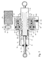
- FIG. 7 A further embodiment of a variable in its length Rad Equipmentsgliedes and in particular the length-adjustable tie rod 15 is in the FIG. 7 shown. This embodiment is preferred because it is less expensive than that in the FIG. 5 illustrated embodiment and ensures a similar high mechanical efficiency.
- the coupling element 67 is thus connected via the rotary / rotary gear directly to the motor shaft 64.
- the drive of the coupling element 67 takes place here via the belt 63, which transmits the rotational movement of the motor shaft 64 to the coupling element 67.
- the coupling device 67 On the circumference of the coupling device 67 here regularly spaced holes 100 are provided, into which one or more associated with the housing 19 magnetic plunger 101, which are actuated by electromagnets 102, can engage positively.
- the engagement is preferably spring-driven with the electromagnet 102 de-energized, while the magnetic plunger 101 is in the freewheeling position when the electromagnet 102 is energized. outside the holes 100, is held.
Landscapes
- Engineering & Computer Science (AREA)
- Mechanical Engineering (AREA)
- Chemical & Material Sciences (AREA)
- Combustion & Propulsion (AREA)
- Transportation (AREA)
- Power Steering Mechanism (AREA)
- Steering-Linkage Mechanisms And Four-Wheel Steering (AREA)
Applications Claiming Priority (4)
| Application Number | Priority Date | Filing Date | Title |
|---|---|---|---|
| DE102005020396 | 2005-05-02 | ||
| DE102005020422 | 2005-05-02 | ||
| DE102006020041A DE102006020041A1 (de) | 2005-05-02 | 2006-04-26 | Lenkvorrichtung, insbesondere für eine Hinterradlenkung |
| PCT/EP2006/061925 WO2006117343A1 (de) | 2005-05-02 | 2006-04-28 | Lenkvorrichtung, insbesondere für eine hinterradlenkung |
Publications (2)
| Publication Number | Publication Date |
|---|---|
| EP1879781A1 EP1879781A1 (de) | 2008-01-23 |
| EP1879781B1 true EP1879781B1 (de) | 2010-12-29 |
Family
ID=36658781
Family Applications (1)
| Application Number | Title | Priority Date | Filing Date |
|---|---|---|---|
| EP06754924A Active EP1879781B1 (de) | 2005-05-02 | 2006-04-28 | Lenkvorrichtung, insbesondere für eine hinterradlenkung |
Country Status (5)
| Country | Link |
|---|---|
| EP (1) | EP1879781B1 (ko) |
| JP (1) | JP4942739B2 (ko) |
| KR (1) | KR101259206B1 (ko) |
| DE (2) | DE102006020041A1 (ko) |
| WO (1) | WO2006117343A1 (ko) |
Families Citing this family (34)
| Publication number | Priority date | Publication date | Assignee | Title |
|---|---|---|---|---|
| DE102007058143A1 (de) * | 2006-12-04 | 2008-06-05 | Continental Teves Ag & Co. Ohg | System und Verfahren zum Einstellen eines Radeinschlagwinkels eines Rades eines Kraftfahrzeugs |
| DE102007007234A1 (de) * | 2007-02-14 | 2008-08-21 | Audi Ag | Elektromechanische Stellvorrichtung für Radaufhängungen von Kraftfahrzeugen |
| EP1975041B1 (en) | 2007-03-27 | 2013-10-16 | Honda Motor Co., Ltd. | Steering system |
| DE102007024755A1 (de) | 2007-05-26 | 2008-11-27 | Bayerische Motoren Werke Aktiengesellschaft | Aktives Fahrwerksystem eines zweispurigen Fahrzeugs sowie Betriebsverfahren hierfür |
| US8308174B2 (en) | 2007-06-04 | 2012-11-13 | Continental Teves Ag & Ohg | Steering device for adjusting a wheel steering angle |
| JP2009173192A (ja) * | 2008-01-25 | 2009-08-06 | Honda Motor Co Ltd | 後輪操舵装置 |
| DE102008012686A1 (de) | 2008-03-05 | 2009-09-10 | Audi Ag | Stellglied für ein Radführungselement von Radaufhängungen |
| JP5311862B2 (ja) * | 2008-03-31 | 2013-10-09 | 本田技研工業株式会社 | 操舵装置 |
| DE102009039164A1 (de) * | 2008-12-09 | 2010-06-10 | Continental Teves Ag & Co. Ohg | Lenkvorrichtung, insbesondere für eine Hinterradlenkung |
| FR2947234B1 (fr) | 2009-06-30 | 2011-07-15 | Michelin Soc Tech | Ensemble routier comprenant un vehicule et un train de pneus. |
| KR101126248B1 (ko) * | 2009-12-03 | 2012-03-20 | 현대자동차주식회사 | 스티어 바이 와이어 장치 |
| DE102011085607A1 (de) | 2010-11-03 | 2012-07-12 | Continental Automotive Gmbh | Lenkvorrichtung für eine Hinterradlenkung und Verfahren zu deren Betrieb |
| US8979046B2 (en) * | 2010-11-16 | 2015-03-17 | Chul Seok Woo | Vacuum adsorbing device |
| DE102011006890A1 (de) | 2011-04-06 | 2012-10-11 | Zf Friedrichshafen Ag | Lenkvorrichtung, insbesondere für eine Hinterradlenkung |
| FR2973734B1 (fr) * | 2011-04-06 | 2013-05-17 | Renault Sa | Essieu arriere directeur de vehicule automobile |
| ITBO20120006A1 (it) * | 2012-01-05 | 2013-07-06 | Ferrari Spa | Attuatore lineare elettromagnetico con dispositivo frenante per variare la geometria di una sospensione attiva di una vettura |
| ITBO20120005A1 (it) * | 2012-01-05 | 2013-07-06 | Ferrari Spa | Attuatore lineare elettromagnetico per variare la geometria di una sospensione attiva di una vettura |
| DE102012212608A1 (de) | 2012-07-18 | 2014-02-06 | Schaeffler Technologies AG & Co. KG | Aktuator für eine elektronisch gesteuerte elektromechanische Lenkung für schwere Nutzfahrzeuge |
| JP6110732B2 (ja) * | 2013-06-03 | 2017-04-05 | 本田技研工業株式会社 | 伸縮アクチュエータ |
| DE102013211230A1 (de) * | 2013-06-17 | 2014-12-18 | Schaeffler Technologies Gmbh & Co. Kg | Vorrichtung zum Lenken einer Hinterachse eines Kraftfahrzeugs |
| DE102013211538A1 (de) * | 2013-06-19 | 2014-12-24 | Zf Friedrichshafen Ag | Radaufhängung mit Querblattfeder |
| JP2016084011A (ja) * | 2014-10-24 | 2016-05-19 | アイシン精機株式会社 | 車両の後輪操舵装置 |
| JP2016147513A (ja) * | 2015-02-10 | 2016-08-18 | Ntn株式会社 | 後輪転舵装置 |
| DE102015206228A1 (de) | 2015-04-08 | 2016-10-13 | Volkswagen Aktiengesellschaft | Anordnung und Verfahren zur Ermittlung eines Lenkwinkels einer lenkbaren Hinterachse |
| JP2016203758A (ja) * | 2015-04-21 | 2016-12-08 | アイシン精機株式会社 | 車両の後輪操舵装置 |
| DE102016208317A1 (de) * | 2016-05-13 | 2017-11-16 | Zf Friedrichshafen Ag | Lenkgetriebevorrichtung und Fahrzeug |
| DE102016211342B4 (de) | 2016-06-24 | 2021-05-06 | Zf Friedrichshafen Ag | Lenkvorrichtung für ein Kraftfahrzeug |
| KR102530701B1 (ko) * | 2017-02-28 | 2023-05-10 | 현대모비스 주식회사 | 후륜 조향장치 |
| DE102017211672A1 (de) * | 2017-07-07 | 2019-01-10 | Zf Friedrichshafen Ag | Verstelleinrichtung für ein Fahrwerk eines Kraftfahrzeuges sowie Hinterachslenkung |
| DE102017221289B4 (de) | 2017-11-28 | 2023-06-29 | Robert Bosch Gmbh | Risikominimaler Zustand in einem steer-by-wire-Lenksystem |
| JP6572291B2 (ja) * | 2017-11-28 | 2019-09-04 | 本田技研工業株式会社 | アクチュエータのロック機構 |
| KR20230111245A (ko) | 2021-02-08 | 2023-07-25 | 닛본 세이고 가부시끼가이샤 | 역입력 차단 클러치 |
| DE102021211594A1 (de) | 2021-10-14 | 2023-04-20 | Zf Friedrichshafen Ag | Lenker mit elastischem Lager umfassend magnetoelastisches und/oder elektroaktives Material |
| CN115107869A (zh) * | 2022-07-06 | 2022-09-27 | 北京汽车集团越野车有限公司 | 一种后轮转向对中锁止机构 |
Family Cites Families (12)
| Publication number | Priority date | Publication date | Assignee | Title |
|---|---|---|---|---|
| JPS58214470A (ja) * | 1982-06-07 | 1983-12-13 | Nissan Motor Co Ltd | 後輪操舵装置 |
| JPS6280173A (ja) * | 1985-10-03 | 1987-04-13 | Mazda Motor Corp | 車両の4輪操舵装置 |
| IT1212162B (it) * | 1987-12-30 | 1989-11-08 | Fiat Auto Spa | Sospensione posteriore per autoveicoli del tipo a ruote indipendenti a quadrilateri trasversali |
| IT1217427B (it) * | 1988-04-18 | 1990-03-22 | Alfa Lancia Ind | Dispositivo di regolazione della lunghezza dei bracci di sospensioni di autoveicoli |
| DE3827039A1 (de) * | 1988-08-10 | 1990-02-15 | Bayerische Motoren Werke Ag | Vorrichtung zur radstellungsaenderung von kraftfahrzeugraedern |
| JPH03153472A (ja) * | 1989-11-07 | 1991-07-01 | Aisin Aw Co Ltd | 後輪操舵装置及び方法 |
| DE4020547A1 (de) * | 1990-06-28 | 1992-01-02 | Porsche Ag | Vorrichtung zur aktiven verstellung eines kraftfahrzeugrades |
| JPH0761363A (ja) * | 1992-07-23 | 1995-03-07 | Norinaga Yokoyama | 後輪方向制御装置及び車両 |
| JPH08337106A (ja) * | 1995-06-13 | 1996-12-24 | Toyota Motor Corp | 車輪操舵装置 |
| JP3476972B2 (ja) * | 1995-07-17 | 2003-12-10 | 本田技研工業株式会社 | 後輪転舵装置 |
| DE10064585A1 (de) * | 2000-12-22 | 2002-09-12 | Woelk Adalbert | Variable Radwinkelsteuerung |
| JP4104346B2 (ja) * | 2002-02-21 | 2008-06-18 | 本田技研工業株式会社 | 車両用後輪操舵装置 |
-
2006
- 2006-04-26 DE DE102006020041A patent/DE102006020041A1/de not_active Ceased
- 2006-04-28 WO PCT/EP2006/061925 patent/WO2006117343A1/de not_active Application Discontinuation
- 2006-04-28 JP JP2008509421A patent/JP4942739B2/ja active Active
- 2006-04-28 DE DE502006008607T patent/DE502006008607D1/de active Active
- 2006-04-28 EP EP06754924A patent/EP1879781B1/de active Active
- 2006-04-28 KR KR1020077025380A patent/KR101259206B1/ko active IP Right Grant
Also Published As
| Publication number | Publication date |
|---|---|
| EP1879781A1 (de) | 2008-01-23 |
| WO2006117343A1 (de) | 2006-11-09 |
| DE502006008607D1 (de) | 2011-02-10 |
| DE102006020041A1 (de) | 2007-03-15 |
| JP4942739B2 (ja) | 2012-05-30 |
| KR101259206B1 (ko) | 2013-04-29 |
| JP2008540209A (ja) | 2008-11-20 |
| KR20080002917A (ko) | 2008-01-04 |
Similar Documents
| Publication | Publication Date | Title |
|---|---|---|
| EP1879781B1 (de) | Lenkvorrichtung, insbesondere für eine hinterradlenkung | |
| EP3691943B1 (de) | Mechanische bremsvorrichtung | |
| DE102018214188A1 (de) | Elektromechanisch-hydraulischer Kolbenaktuator und Bremssystem | |
| EP1268257B1 (de) | Fahrzeuglenkung und achslenkmodul für eine fahrzeuglenkung | |
| EP0916568B1 (de) | Aktuator zum Erzeugen eines zusätzlichen Lenkwinkels für Strassenfahrzeuge | |
| DE10150803B4 (de) | Hydraulische Fahrzeugbremse mit elektrisch betätigbarer Feststelleinrichtung | |
| WO2008148817A1 (de) | Lenkvorrichtung zum einstellen eines radeinschlagwinkels | |
| EP2931573B1 (de) | Bremseinheit für ein fahrzeug und fahrzeug mit einer derartigen bremseinheit | |
| EP2934975B1 (de) | Bremseinheit für ein fahrzeug und fahrzeug mit einer derartigen bremseinheit | |
| DE102006020487A1 (de) | Lenkvorrichtung, insbesondere für eine Hinterachslenkung | |
| DE19741869A1 (de) | Vorrichtung zur Betätigung einer elektromagnetischen Bremse eines Fahrzeuges | |
| DE69017948T2 (de) | Blockierschutz-Bremssystem. | |
| DE10127592B4 (de) | Fahrstabilisierungsverfahren für ein Kraftfahrzeug | |
| DE19741867C1 (de) | Bremsaktuator | |
| EP3807143B1 (de) | Steer-by-wire-lenkung mit einem spindelantrieb | |
| EP1384913B1 (de) | Scheibenbremse, insbesondere für Landfahrzeuge | |
| WO2006114265A1 (de) | Aktuator | |
| DE102021200369B3 (de) | Verfahren sowie Steuereinheit zum Betreiben eines Aktuators einer steer-by-wire-Lenkung | |
| EP3980661B1 (de) | Bremsvorrichtung | |
| EP1181178B1 (de) | Radantrieb für ein mobilfahrzeug | |
| EP0237840A2 (de) | Betätigungseinrichtung für eine kraftschlüssige Sperrkupplung eines sperrbaren Differentialgetriebes für Kraftfahrzeuge | |
| WO2019042861A1 (de) | Fussbremsmodul mit notlenkfunktion | |
| AT524955B1 (de) | Plattform für mindestens vierrädrige Kraftfahrzeuge mit Elektroantrieb | |
| EP2951073B1 (de) | Bremseinheit für ein fahrzeug und fahrzeug mit einer derartigen bremseinheit | |
| AT525556B1 (de) | Verfahren zum Betreiben eines Kraftfahrzeuges mit Elektro-Antrieb |
Legal Events
| Date | Code | Title | Description |
|---|---|---|---|
| PUAI | Public reference made under article 153(3) epc to a published international application that has entered the european phase |
Free format text: ORIGINAL CODE: 0009012 |
|
| 17P | Request for examination filed |
Effective date: 20071203 |
|
| AK | Designated contracting states |
Kind code of ref document: A1 Designated state(s): DE FR HU IT |
|
| 17Q | First examination report despatched |
Effective date: 20080222 |
|
| DAX | Request for extension of the european patent (deleted) | ||
| RBV | Designated contracting states (corrected) |
Designated state(s): DE FR HU IT |
|
| GRAP | Despatch of communication of intention to grant a patent |
Free format text: ORIGINAL CODE: EPIDOSNIGR1 |
|
| GRAS | Grant fee paid |
Free format text: ORIGINAL CODE: EPIDOSNIGR3 |
|
| GRAA | (expected) grant |
Free format text: ORIGINAL CODE: 0009210 |
|
| AK | Designated contracting states |
Kind code of ref document: B1 Designated state(s): DE FR HU IT |
|
| REF | Corresponds to: |
Ref document number: 502006008607 Country of ref document: DE Date of ref document: 20110210 Kind code of ref document: P |
|
| REG | Reference to a national code |
Ref country code: DE Ref legal event code: R096 Ref document number: 502006008607 Country of ref document: DE Effective date: 20110210 |
|
| PLBI | Opposition filed |
Free format text: ORIGINAL CODE: 0009260 |
|
| PLAX | Notice of opposition and request to file observation + time limit sent |
Free format text: ORIGINAL CODE: EPIDOSNOBS2 |
|
| 26 | Opposition filed |
Opponent name: ZF FRIEDRICHSHAFEN AG Effective date: 20110929 |
|
| REG | Reference to a national code |
Ref country code: DE Ref legal event code: R026 Ref document number: 502006008607 Country of ref document: DE Effective date: 20110929 |
|
| PLBB | Reply of patent proprietor to notice(s) of opposition received |
Free format text: ORIGINAL CODE: EPIDOSNOBS3 |
|
| PG25 | Lapsed in a contracting state [announced via postgrant information from national office to epo] |
Ref country code: HU Free format text: LAPSE BECAUSE OF FAILURE TO SUBMIT A TRANSLATION OF THE DESCRIPTION OR TO PAY THE FEE WITHIN THE PRESCRIBED TIME-LIMIT Effective date: 20101229 |
|
| REG | Reference to a national code |
Ref country code: FR Ref legal event code: PLFP Year of fee payment: 11 |
|
| REG | Reference to a national code |
Ref country code: FR Ref legal event code: PLFP Year of fee payment: 12 |
|
| PLCK | Communication despatched that opposition was rejected |
Free format text: ORIGINAL CODE: EPIDOSNREJ1 |
|
| APAH | Appeal reference modified |
Free format text: ORIGINAL CODE: EPIDOSCREFNO |
|
| APBM | Appeal reference recorded |
Free format text: ORIGINAL CODE: EPIDOSNREFNO |
|
| APBP | Date of receipt of notice of appeal recorded |
Free format text: ORIGINAL CODE: EPIDOSNNOA2O |
|
| APBQ | Date of receipt of statement of grounds of appeal recorded |
Free format text: ORIGINAL CODE: EPIDOSNNOA3O |
|
| REG | Reference to a national code |
Ref country code: FR Ref legal event code: PLFP Year of fee payment: 13 |
|
| RAP2 | Party data changed (patent owner data changed or rights of a patent transferred) |
Owner name: CONTINENTAL TEVES AG & CO. OHG |
|
| REG | Reference to a national code |
Ref country code: DE Ref legal event code: R084 Ref document number: 502006008607 Country of ref document: DE |
|
| REG | Reference to a national code |
Ref country code: DE Ref legal event code: R100 Ref document number: 502006008607 Country of ref document: DE |
|
| APBU | Appeal procedure closed |
Free format text: ORIGINAL CODE: EPIDOSNNOA9O |
|
| PLBN | Opposition rejected |
Free format text: ORIGINAL CODE: 0009273 |
|
| STAA | Information on the status of an ep patent application or granted ep patent |
Free format text: STATUS: OPPOSITION REJECTED |
|
| 27O | Opposition rejected |
Effective date: 20200918 |
|
| REG | Reference to a national code |
Ref country code: DE Ref legal event code: R081 Ref document number: 502006008607 Country of ref document: DE Owner name: CONTINENTAL AUTOMOTIVE TECHNOLOGIES GMBH, DE Free format text: FORMER OWNER: CONTINENTAL TEVES AG & CO. OHG, 60488 FRANKFURT, DE |
|
| P01 | Opt-out of the competence of the unified patent court (upc) registered |
Effective date: 20230522 |
|
| PGFP | Annual fee paid to national office [announced via postgrant information from national office to epo] |
Ref country code: DE Payment date: 20240430 Year of fee payment: 19 |
|
| PGFP | Annual fee paid to national office [announced via postgrant information from national office to epo] |
Ref country code: IT Payment date: 20240424 Year of fee payment: 19 Ref country code: FR Payment date: 20240426 Year of fee payment: 19 |