EP1870232B1 - Formstempel für eine Faltschachtelherstellungsmaschine - Google Patents
Formstempel für eine Faltschachtelherstellungsmaschine Download PDFInfo
- Publication number
- EP1870232B1 EP1870232B1 EP07380181A EP07380181A EP1870232B1 EP 1870232 B1 EP1870232 B1 EP 1870232B1 EP 07380181 A EP07380181 A EP 07380181A EP 07380181 A EP07380181 A EP 07380181A EP 1870232 B1 EP1870232 B1 EP 1870232B1
- Authority
- EP
- European Patent Office
- Prior art keywords
- push head
- holes
- head according
- opposite
- fixing
- Prior art date
- Legal status (The legal status is an assumption and is not a legal conclusion. Google has not performed a legal analysis and makes no representation as to the accuracy of the status listed.)
- Not-in-force
Links
- 230000008878 coupling Effects 0.000 claims abstract description 20
- 238000010168 coupling process Methods 0.000 claims abstract description 20
- 238000005859 coupling reaction Methods 0.000 claims abstract description 20
- 238000009434 installation Methods 0.000 claims abstract description 8
- 238000000605 extraction Methods 0.000 claims description 2
- 238000003780 insertion Methods 0.000 claims description 2
- 230000037431 insertion Effects 0.000 claims description 2
- 238000010276 construction Methods 0.000 description 2
- 238000000465 moulding Methods 0.000 description 2
- 229910000831 Steel Inorganic materials 0.000 description 1
- XAGFODPZIPBFFR-UHFFFAOYSA-N aluminium Chemical compound [Al] XAGFODPZIPBFFR-UHFFFAOYSA-N 0.000 description 1
- 229910052782 aluminium Inorganic materials 0.000 description 1
- 230000015572 biosynthetic process Effects 0.000 description 1
- 239000000463 material Substances 0.000 description 1
- 238000012986 modification Methods 0.000 description 1
- 230000004048 modification Effects 0.000 description 1
- 239000010959 steel Substances 0.000 description 1
- 238000003466 welding Methods 0.000 description 1
Images




Classifications
-
- B—PERFORMING OPERATIONS; TRANSPORTING
- B31—MAKING ARTICLES OF PAPER, CARDBOARD OR MATERIAL WORKED IN A MANNER ANALOGOUS TO PAPER; WORKING PAPER, CARDBOARD OR MATERIAL WORKED IN A MANNER ANALOGOUS TO PAPER
- B31B—MAKING CONTAINERS OF PAPER, CARDBOARD OR MATERIAL WORKED IN A MANNER ANALOGOUS TO PAPER
- B31B50/00—Making rigid or semi-rigid containers, e.g. boxes or cartons
-
- B—PERFORMING OPERATIONS; TRANSPORTING
- B31—MAKING ARTICLES OF PAPER, CARDBOARD OR MATERIAL WORKED IN A MANNER ANALOGOUS TO PAPER; WORKING PAPER, CARDBOARD OR MATERIAL WORKED IN A MANNER ANALOGOUS TO PAPER
- B31B—MAKING CONTAINERS OF PAPER, CARDBOARD OR MATERIAL WORKED IN A MANNER ANALOGOUS TO PAPER
- B31B50/00—Making rigid or semi-rigid containers, e.g. boxes or cartons
- B31B50/26—Folding sheets, blanks or webs
- B31B50/44—Folding sheets, blanks or webs by plungers moving through folding dies
-
- B—PERFORMING OPERATIONS; TRANSPORTING
- B31—MAKING ARTICLES OF PAPER, CARDBOARD OR MATERIAL WORKED IN A MANNER ANALOGOUS TO PAPER; WORKING PAPER, CARDBOARD OR MATERIAL WORKED IN A MANNER ANALOGOUS TO PAPER
- B31B—MAKING CONTAINERS OF PAPER, CARDBOARD OR MATERIAL WORKED IN A MANNER ANALOGOUS TO PAPER
- B31B50/00—Making rigid or semi-rigid containers, e.g. boxes or cartons
- B31B50/26—Folding sheets, blanks or webs
- B31B50/44—Folding sheets, blanks or webs by plungers moving through folding dies
- B31B50/46—Folding sheets, blanks or webs by plungers moving through folding dies and interconnecting side walls
Definitions
- the present invention relates to a push head for a cardboard box forming machine starting from flat, die-cut cardboard templates.
- Patent documents US-A-2798416 , ES-A-0442914 , ES-A-0550143 , ES-A-235835-U and ES-A-255122-U disclose automatic open cardboard box assembling machines starting from flat templates, generally comprising four corner forming units arranged as vertical columns defining a molding cavity on which a flat die-cut cardboard template supplied sequentially by a feed device is horizontally introduced. The flat die-cut cardboard template is then pushed downwards by a push head joined to a moving arm of the machine, each of said corner units cooperating in the formation of the box by folding several parts of the flat cardboard template.
- Spanish addition patent application N° 200402985 relating to Spanish patent application N° 200302184 describes a push head for a cardboard box forming machine comprising a support structure formed from two longitudinal side plates joined by three transverse bridges, one of which is a central bridge defining a fixing base adapted to be joined to a moving member of the machine that is able to transmit an up-down reciprocating movement to said support structure. Assembled at the ends of the side plates there are corner posts and a swiveling thruster is assembled at each of the two end bridges.
- the push head includes several adjustable fixing devices to adjust the relative positions of the side plates, bridges, corner posts and swiveling thrusters for the purpose of adapting the push head to different box formats and allowing operation adjustments.
- the present invention provides a push head for a cardboard box forming machine comprising a support structure provided with a fixing base adapted to be joined to a moving member of said machine that is able to transmit an up-down movement to said support structure, four swiveling thrusters projecting from four corresponding corners of said support structure, two on one side and two others on the other opposite side in a longitudinal direction.
- Each swiveling thruster is individually assembled to rotate about a horizontal shaft and in cooperation with a rotation limiter which keeps it stiff so as to press against a cardboard box template during a downward movement and which allows it to pivot so as to overcome a flap of the cardboard box during an upward movement.
- Adjustment means allow adjusting the distances between the swiveling thrusters in the longitudinal and transverse directions of the support structure.
- the support structure comprises first and second side plates arranged longitudinally on opposite sides and joined to one another by means of a transverse bridge having adjustable length and several transverse bars also having adjustable length.
- the mentioned transverse bridge supports the fixing base, and is assembled such that its position can be adjusted in the vertical direction in relation to the first and second side plates.
- the swiveling thrusters are assembled in respective supports fixed to the first and second side plates such that their position can be individually adjusted in the longitudinal direction.
- This construction is simplified in relation to the push heads of the state of the art and allows precise adjustments in the longitudinal, transverse and vertical directions in a fast and practical manner.
- the transverse bridge further has fixed thereto several hooks projecting above the fixing base. These hooks are adapted to engage a coupling member joined to said moving member for the purpose of temporarily supporting the push head during a push head installation or removal operation.
- FIG 1 shows a push head for a cardboard box forming machine according to an embodiment of the present invention.
- the push head comprises a support structure 1 formed from first and second side plates 6a, 6b arranged longitudinally on opposite sides of the structure.
- the mentioned first and second side plates 6a, 6b are joined to one another by a transverse bridge 8 having adjustable length and several transverse bars 7 also having adjustable length.
- a fixing base 2 adapted to be joined to a moving member 3 (shown in Figures 2 and 3 ) of said machine.
- the mentioned moving member is actuated to transmit an up-down reciprocating movement to the support structure 1.
- the support structure 1 has a general rectangular shape with a longitudinal dimension and a transverse dimension, and is substantially symmetrical both in relation to a longitudinal vertical midplane and in relation to a transverse vertical midplane. Projecting from the four corners of the support structure 1 there are four corresponding swiveling thrusters 4, two on one side and two others on the other opposite side in the longitudinal direction.
- the transverse bridge 8 comprises a central body 10 with an upper part in which the fixing base 2 is defined and opposite side faces 12 in which guide grooves 11 are defined. Coupled in each of such guide grooves in a sliding manner there is a first guide member 13a projecting on one side and a second guide member 13b projecting on the other opposite side. Therefore projecting from one side of the central body there are two first guide members 13a joined to the first side plate 6a in an adjustable manner in the vertical direction, and projecting from the other opposite side there are two second guide members 13b joined to the second side plate 6b in an adjustable manner in the vertical direction.
- the transverse bridge includes fixing means for fixing the first and second guide members 13a, 13b to the central body 10 in an adjustable manner in the transverse direction comprising round holes 22 formed in the guide members 13a, 13b opposite to elongated holes 23 formed in the central body 10, or vice versa, said round holes 22 and corresponding elongated holes 23 are traversed by locking screws 24 screwed into screw threads formed in the round holes 22 of some of said guide members. Alternatively, the locking screws could be tightened by respective nuts.
- the first and second guide members 13a, 13b can slide along the guide grooves 11 of the central body 10 to reduce or increase the length of the transverse bridge 8 or to simply shift the central body 10 without changing the length of the transverse bridge 8.
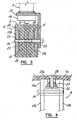
- the mentioned moving member 3 of the machine ends in a coupling member 16 adapted to be joined to the fixing base 2 of the push head.
- Formed in the fixing base 2 there are centering holes 18 adapted to receive corresponding centering lugs 17 projecting from the lower part of the coupling member 16, or vice versa.
- Formed in the fixing base 2 there are also holes 20 opposite to corresponding holes 19 existing in the coupling member 16. These holes 19, 20 are adapted for installing vertical locking screws (not shown) for joining the push head to the moving member 3.
- the central body 10 has fixed thereto, for example by means of some of the same locking screws 24 joining the first and second guide members 13a, 13b to the central body 10, hooks 15 projecting above the fixing base 2.
- the mentioned hooks 15 are adapted to engage in the coupling member 16 joined to said moving member 3 for the purpose of temporarily supporting the push head during a push head installation or removal operation.
- the mentioned centering lugs 17 remain opposite to said centering holes 18, though outside of them, and the holes 19 of the coupling member 16 remain opposite to the holes 20 of the fixing base 2, as shown in Figure 2 .
- the mentioned vertical locking screws have a suitable length to project from the lower end of the holes 20 of the fixing base 2 and to couple, for example, to corresponding nuts when the push head is supported by the hooks 15 in the coupling member 16.
- slowly tightening the vertical locking screws allows bringing the coupling member 16 closer to the fixing base 2 with the insertion of the centering lugs 17 in the centering holes 18 until fixedly joining the push head to the moving member 3 during a push head installation operation.
- slowly loosening the vertical locking screws allows gradually separating the coupling member 16 from the fixing base 2 with the extraction of the centering lugs 17 from the centering holes 18 until the hooks 15 rest on the coupling member 16. Therefore, by virtue of the hooks 15, a single operator can install and remove the push head easily and without making any unnecessary efforts.
- first and second guide members 13a, 13b are fixed to a first block 14a, which is assembled such that it can be shifted along a first vertical guide 25a formed or arranged in the first side plate 6a
- second guide members 13b are fixed to a second block 14b assembled such that it can be shifted along a second vertical guide 25b formed or arranged in the second side plate 6b (also see Figure 1 ).
- the first and second guide members 13a, 13b are fixed to the corresponding first and second blocks by means of screws 34.
- fixing means comprising a trapezium-shaped groove 26 formed in each first and second block 14a, 14b in the vertical direction, each trapezium-shaped groove 26 being opposite to its corresponding first and second side plate 6a, 6b.
- a trapezium-shaped bar 27 is inserted in a sliding manner in each trapezium-shaped groove 26, and locking screws 28 traverse opposite holes of the corresponding trapezium-shaped bar 27 and of the first or second side plate 6a, 6b. Tightening said locking screws 28 brings each trapezium-shaped bar 27 towards the corresponding first or second side plate 6a, 6b and presses it against the vertical guide 25a, 25b, thus locking the corresponding first or second block 14a, 14b.
- FIG. 5 and 6 show one of the four swiveling thrusters 4, and the description thereof can also be used for the three other swiveling thrusters 4, which are equal and/or symmetrical to the one shown in Figures 5 and 6 .
- Each of the swiveling thrusters 4 is assembled in a respective support 9 fixed to the first or second side plate 6a, 6b such that its position can be adjusted individually in the longitudinal direction.
- the mentioned support 9 has an overturned U shape and comprises two opposite parallel plates between which a rear portion of the swiveling thruster 4 is arranged.
- a horizontal shaft 5 traversing the swiveling thruster 4 and a pin 29 adjacent thereto extend from one of the side plates of the support 9 to the other.
- the swiveling thruster 4 can rotate about the horizontal shaft 5 and the pin 29 acts as a rotation limiter.
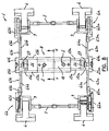
- the longitudinal shafts 5 of two of the swiveling thrusters 4 located at the same longitudinal end of the support structure 1 can optionally be aligned and connected with the two rods forming part of one of the transverse bars 7 having adjustable length ( Fig. 1 ).
- the rotation limiter keeps the swiveling thruster 4 stiff (as it is shown by means of continuous lines in Figure 6 ) to press the cardboard box template towards the inside of the molding cavity of the machine forcing the folding of the flaps for forming the open cardboard box. Then when the push head carries out an upward movement, the swiveling thruster 4 can pivot (towards the position shown by means of dotted lines in Figure 6 ) in order to overcome a flap of the formed cardboard box.
- Each swiveling thruster 4 is associated to a corresponding elastic element 33 ( Fig. 1 ) arranged to push the swiveling thruster 4 towards the mentioned stiff position in contact with the rotation limiter pin 29.
- the push head includes adjustment means to adjust the distances between the swiveling thrusters 4 in the longitudinal direction of the support structure 1.
- one of the two opposite parallel plates of each support 9 has threaded holes 30, which are opposite to elongated holes 31 formed in the corresponding first or second side plate 6a, 6b ( Fig. 6 ).
- Locking screws 32 traverse said elongated holes 31 and are screwed in said threaded holes 30 to lock the support 9 in relation to the side plate 6a, 6b.
- a perimetral step 35 in which plates 36 provided with holes are arranged for the locking screws 32, and the locking screws 32 have heads which press against said plates 36.
- first and second longitudinal side plates 6a, 6b of the support structure 1 therein are formed by respective first and second central portions 61a, 61b and respective first and second end portions 62a, 62b.
- the mentioned first and second central portions 61 a, 61b are joined to opposite ends of said transverse bridge 8, and said first and second end portions 62a, 62b are joined to opposite sides of their corresponding central portion 61a, 61b by connecting members 63a, 63b having adjustable length.
- the supports 9 in which the swiveling thrusters 4 are assembled are fixed to the first and second end portions 62a, 62b, an adjustment of the length of the mentioned connecting members 63a, 63b allows adjusting the length of the push head determined by the positions of the swiveling thrusters 4.
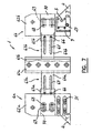
- each of the supports 9 of the swiveling thrusters 4 is fixed to its corresponding end portion 62a, 62b by means including screws traversing elongated holes 31 ( Fig. 7 ) similar to those described above in relation to Figure 6 , such that the position of each of the swiveling thrusters 4 can be additionally adjusted in the longitudinal direction in relation to its corresponding end portion 62a, 62b.
- the first and second central portions 61a, 61b of the side plates 6a, 6b are metallic, for example steel or aluminum, and each of the mentioned connecting members 63a, 63b comprises a slider rail 64a, 64b rigidly fixed at one of its ends, preferably by welding, to the corresponding central portion 61a, 61b of the side plate 6a, 6b.
- Each slider rail 64a, 64b is inserted in a sliding manner in a groove defined in a guide part 65a, 65b, which in turn is fixed to its corresponding first or second end portion 62a, 62b of the side plate 6a, 6b.
- the first and second end portions 62a, 62b of the side plates 6a, 6b are made of a plastic material, and each guide part 65a, 65b is coupled in a sliding manner in a recessed area 70 of the corresponding first or second end portion 62a, 62b ( Fig. 7 ).
- the guide part 65a, 65b has holes 68 adapted for installing locking screws cooperating with elongated holes 69 formed in the first or second end portion 62a, 62b for fixing the guide part 65a, 65b to the first or second end portion 62a, 62b in a selected position, which provides the possibility of an additional adjustment of the dimension of the push head in the longitudinal direction.
- transverse bars 7 having adjustable length are connected at their ends to the first and second end portions 62a, 62b.
- two of these transverse bars 7 having adjustable length namely those which are located at a lower level, are connected at their ends to the supports 9, which in turn are fixed to the corresponding first and second end portions 62a, 62b as described above.
- the transverse bridge 8 is formed by a central body 10 and first and second guide members 13a, 13b.
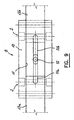
- each of the mentioned guide grooves 11 of the central body 10 has sufficient depth so as to house, mutually overlapped, the mentioned first and second guide members 13a, 13b, such that the first and second guide members 13a, 13b can slide in their guide groove with respect to one another and in turn with respect to the central body 10.
- the first guide members 13a have elongated holes 71a and the second guide members 13b also have elongated holes 71b, which, in an operative position, partially overlap the mentioned elongated holes 71a of first guide members 13a.
- the overlapping area of the elongated holes 71a, 71b of the first and second guide members 13a, 13b is opposite to a transverse hole 72 formed in the central body 10. Therefore, a locking screw installed through said transverse hole 72 and said elongated holes 71a, 71b can be tightened to fix the first and second guide members 13a, 13b to the central body 10 in selected positions.
- the overlapping arrangement of the first and second guide members 13a, 13b and of the elongated holes 71a, 72a provides this second embodiment with greater adjustment capacity of the transverse dimension of the push head in comparison with the first embodiment.
- first and second guide members 13a, 13b are fixed at their ends farthest from the central body 10 to respective first and second blocks 14a, 14b, which are assembled such that they can be shifted along corresponding first and second vertical guides 25a, 25b formed in the first and second central portions 61a, 61b.
- Fixing means are arranged for fixing the positions of the first and second blocks 14a, 14b in relation to the first and second central portions 61a, 61b, respectively, whereby providing a possibility of adjusting the vertical position of the push head in relation to the moving member 3 of the cardboard box assembling machine.
- the mentioned fixing means comprise, for each side plate 6a, 6b, a trapezium-shaped bar 27 inserted in a sliding manner in a corresponding trapezium-shaped groove 26 formed in the corresponding first or second block 14a.
- a series of threaded holes are formed along said trapezium-shaped bar 27, which holes are opposite to a series of holes formed in the corresponding first or second central portion 61a, 61b of the first or second side plate 6a, 6b.
- Locking screws 28 are inserted through said opposite holes, which locking screws, when tightened, bring the trapezium-shaped bar 27 towards the corresponding first or second central portion 61a, 61b and press it against the vertical guide 25a, 25b, thus locking the corresponding first or second block 14a, 14b.
- Figure 11 only shows the fixing means on one side of the push head, given that the fixing means on the opposite side are identical.
Landscapes
- Making Paper Articles (AREA)
- Connection Of Plates (AREA)
Claims (19)
- Schiebekopf für eine Kartonformmaschine, derart umfassend eine Stützstruktur (1), welche mit einem Fixierboden (1) versehen ist, der dazu angepasst ist, mit einem beweglichen Glied (3) der genannten Maschine verbunden zu werden, welches eine Auf- und Abwärtsbewegung auf die genannte Stützstruktur (1) übertragen kann, vier Schwenkschubvorrichtungen (4), welche an vier entsprechenden Ecken der genannten Stützstruktur (1) überstehen, zwei auf einer Seite und weitere zwei auf der anderen gegenüberliegenden Seite in Längsrichtung, wobei jede Schwenkschubvorrichtung (4) individuell zusammengebaut ist, um sich um eine horizontale Welle (5) und zusammen mit einer Drehsperre zu drehen, welche sie starr hält, um während einer Abwärtsbewegung gegen eine Kartonschablone gepresst zu werden, und welche ihr ein Schwenken ermöglicht, um eine Klappe des Kartons während einer Aufwärtsbewegung zu überwinden, und Stellmittel zum Einstellen der Abstände zwischen den Schwenkschubvorrichtungen (4) in der Längs- und Querrichtung der Stützstruktur (1), dadurch gekennzeichnet, dass die Stützstruktur (1) eine erste und eine zweite Längsseitenplatte (6a, 6b) auf gegenüberliegenden Seiten in der Querrichtung umfasst, welche miteinander durch einen Quersteg (8) mit einstellbarer Länge und mehrere Querstangen (7) mit einstellbarer Länge verbunden sind, wobei der genannte Quersteg (8) den genannten Fixierboden (2) trägt und derart zusammengebaut ist, dass seine Position in vertikaler Richtung in Bezug auf die genannte erste und zweite Seitenplatte (6a, 6b) eingestellt werden kann, und wobei die Schwenkschubvorrichtungen (4) in jeweiligen Stützen (9) zusammengebaut sind, welche an der ersten und zweiten Seitenplatte (6a, 6b) fixiert sind, so dass ihre Position individuell in Längsrichtung eingestellt werden kann.
- Schiebekopf nach Anspruch 1, dadurch gekennzeichnet, dass an dem Quersteg (8) Haken (15) fixiert sind, welche über den Fixierboden (2) überstehen, wobei die genannten Haken (15) dazu angepasst sind, in ein Koppelglied (16) einzugreifen, welches mit dem genannten beweglichen Glied (3) verbunden ist, um den Schiebekopf während eines Installations- oder Entfernungsvorgangs des Schiebekopfs vorübergehend zu stützen.
- Schiebekopf nach Anspruch 1, dadurch gekennzeichnet, dass der genannte Quersteg (8) einen zentralen Körper (10) umfasst, welcher den Fixierboden (2) in einem oberen Teil definiert, und zumindest eine Führungsnut (11), welche dazu angepasst ist, auf einer Seite zumindest ein erstes Führungsglied (13a) aufzunehmen, welches mit der ersten Seitenplatte (6a) in vertikaler Richtung verstellbar verbunden ist, und auf einer gegenüberliegenden Seite zumindest ein zweites Führungsglied (13b), welches mit der zweiten Seitenplatte (6b) in vertikaler Richtung verstellbar verbunden ist, wobei Fixiermittel zum in Querrichtung einstellbaren Fixieren des ersten und zweiten Führungsglieds (13a, 13b) an dem zentralen Körper (10) vorgesehen sind.
- Schiebekopf nach Anspruch 3, dadurch gekennzeichnet, dass an dem zentralen Körper (10) Haken (15) fixiert sind, welche über den Fixierboden (2) überstehen, wobei die genannten Haken (15) dazu angepasst sind, in ein Koppelglied (16) einzugreifen, welches mit dem genannten beweglichen Glied (3) verbunden ist, um den Schiebekopf während eines Installations- oder Entfernungsvorgangs des Schiebekopfs vorübergehend zu stützen.
- Schiebekopf nach Anspruch 4, dadurch gekennzeichnet, dass das genannte Koppelglied (16) Zentrieransätze (17) umfasst, welche dazu angepasst sind, in in dem Fixierboden (2) gebildete Zentrierlöcher (18) eingepasst zu werden, bzw. umgekehrt, wobei die genannten Zentrieransätze (17) den genannten Zentrierlöchern (18) gegenüberliegen, außerhalb derselbigen, wenn der Schiebekopf durch die Haken (15) in dem Koppelglied (16) gestützt wird.
- Schiebekopf nach Anspruch 5, dadurch gekennzeichnet, dass das Koppelglied (16) Löcher (19) umfasst, welche entsprechenden, in dem Fixierboden (2) gebildeten Löchern (20) gegenüberliegen, wobei die genannten Löcher (19, 20) dazu angepasst sind, vertikale Feststellschrauben geeigneter Länge zu installieren, um ein Annähern des Koppelglieds (16) an den Fixierboden (2) mit einem Einsetzen der Zentrieransätze (17) in die Zentrierlöcher (18) zu ermöglichen, bis diese fest verbunden sind, wenn die genannten vertikalen Feststellschrauben während eines Installationsvorgangs des Schiebekopfs angezogen werden, und um ein Trennen des Koppelglieds (16) von dem Fixierboden (2) mit einem Herausziehen der Zentrieransätze (17) aus den Zentrierlöchern (18) zu ermöglichen, bis die Haken (15) auf dem Koppelglied (16) aufliegen, wenn die genannten vertikalen Feststellschrauben während eines Entfernungsvorgangs des Schiebekopfs gelöst werden.
- Schiebekopf nach Anspruch 3, dadurch gekennzeichnet, dass der zentrale Körper (10) zwei der genannten Führungsnuten (11) umfasst, welche in gegenüberliegenden Seitenflächen (12) desselbigen gebildet sind, des Weiteren zwei der genannten ersten Führungsglieder (13a), welche an einem ersten Block (14a) fixiert sind, welcher derart zusammengebaut ist, dass er entlang einer ersten, in der ersten Seitenplatte (6a) angeordneten Vertikalführung (25a) verschoben werden kann, des Weiteren zwei der genannten zweiten Führungsglieder (13b), welche an einem zweiten Block (14b) fixiert sind, welcher derart zusammengebaut ist, dass er entlang einer zweiten, in der zweiten Seitenplatte (6b) angeordneten Vertikalführung (25b) verschoben werden kann, sowie Fixiermittel zum in vertikaler Richtung einstellbaren Fixieren des ersten und zweiten Blocks (14a, 14b) jeweils an der ersten und zweiten Seitenplatte (6a, 6b).
- Schiebekopf nach Anspruch 7, dadurch gekennzeichnet, dass die genannten Fixiermittel zum Fixieren des ersten und zweiten Führungsglieds (13a, 13b) an dem zentralen Körper (10) Rundlöcher (22) umfassen, welche in den Führungsgliedern (13a, 13b) gegenüber von Langlöchern (23) gebildet sind, welche wiederum in dem zentralen Körper (10) gebildet sind, bzw. umgekehrt, sowie Feststellschrauben (24), welche die genannten Rundlöcher (22) und entsprechende Langlöcher (23) durchqueren, und welche dazu angepasst sind, durch eine Mutter angezogen zu werden, oder in Schraubengewinde, welche in einigen der genannten Rundlöcher (22) gebildet sind, eingeschraubt zu werden.
- Schiebekopf nach Anspruch 7, dadurch gekennzeichnet, dass die genannten Fixiermittel zum Fixieren des ersten und zweiten Blocks (14a, 14b) jeweils an der ersten und zweiten Seitenplatte (6a, 6b) eine trapezförmige Nut (26) umfassen, welche in jedem ersten und zweiten Block (14a, 14b) in vertikaler Richtung und gegenüber der entsprechenden ersten und zweiten Seitenplatte (6a, 6b) gebildet ist, des Weiteren eine trapezförmige Stange (27), welche gleitend in jede trapezförmige Nut (26) eingesetzt ist, sowie Feststellschrauben (28), welche gegenüberliegende Löcher der entsprechenden trapezförmigen Stange (27) und der ersten oder zweiten Seitenplatte (6a, 6b) durchqueren, um jede trapezförmige Stange (27) zu der entsprechenden ersten oder zweiten Seitenplatte (6a, 6b) zu pressen, wobei der entsprechende erste oder zweite Block (14a, 14b) blockiert wird.
- Schiebekopf nach Anspruch 1 oder 2, dadurch gekennzeichnet, dass die genannte Stütze (9) jedes Schubelements (4) die Form eines umgedrehten U's hat, und zwei gegenüberliegende, parallele Platten, zwischen welchen sich die genannte horizontale Welle (5) und ein Bolzen (29), welcher als die genannte Drehsperre fungiert, erstrecken.
- Schiebekopf nach Anspruch 10, dadurch gekennzeichnet, dass in einer der genannten gegenüberliegenden, parallelen Platten jeder Stütze (9) Gewindebohrungen (30) gebildet sind, welche Langlöchern (31) gegenüberliegen, welche wiederum in der entsprechenden ersten oder zweiten Seitenplatte (6a, 6b) gebildet sind, wobei Feststellschrauben (32) installiert sind, welche die genannten Langlöcher (31) durchqueren und in den genannten Gewindebohrungen (30) eingeschraubt sind, um die Stütze (9) in Bezug auf die Seitenplatte (6a, 6b) festzustellen.
- Schiebekopf nach Anspruch 10, dadurch gekennzeichnet, dass jede Schwenkschubvorrichtung (4) einem entsprechenden elastischen Element (33) zugeordnet ist, welches angeordnet ist, um die Schwenkschubvorrichtung (4) zu der genannten starren Position zu schieben, welche durch den Kontakt der Schwenkschubvorrichtung (4) gegen den genannten Drehsperrbolzen (29) bestimmt ist.
- Schiebekopf nach Anspruch 1 oder 2, dadurch gekennzeichnet, dass jede der genannten Querstangen (7) mit einstellbarer Länge zwei Stäbe umfasst, welche ein äußeres Gewinde mit umgekehrten Spiralrichtungen aufweisen, welche zueinander fluchten und durch Einschrauben in entsprechende Schraubengewinde gekoppelt sind, welche im Inneren in umgekehrten Spiralrichtungen in gegenüberliegenden Teilen einer Durchgangsbohrung gebildet sind, welche sich in einem Stellglied befindet, welches dazu angepasst ist, von Hand oder durch ein Werkzeug gedreht zu werden.
- Schiebekopf nach einem der Ansprüche 1 bis 13, dadurch gekennzeichnet, dass die genannte erste und zweite Längsseitenplatte (6a, 6b) der Stützstruktur (1) einen jeweiligen ersten und zweiten zentralen Teil (61a, 61b) und einen jeweiligen ersten und zweiten Endteil (62a, 62b) umfassen, in welchen:der genannte erste und zweite zentrale Teil (61a, 61b) mit gegenüberliegenden Enden des genannten Querstegs (8) verbunden ist;der genannte erste und zweite Endteil (62a ,62b) mit gegenüberliegenden Seiten seines entsprechenden zentralen Teils (61a, 61b) durch Anschlussglieder (63a, 63b) mit einstellbarer Länge verbunden ist;die genannten Stützen (9), in welchen die Schwenkschubvorrichtungen (4) zusammengebaut sind, an dem ersten und zweiten Endteil (62a, 62b) fixiert sind; unddie genannten Querstangen (7) mit einstellbarer Länge an ihren Enden an den ersten und zweiten Endteil (62a, 62b) angeschlossen sind.
- Schiebekopf nach Anspruch 14, dadurch gekennzeichnet, dass zumindest zwei der Querstangen (7) mit einstellbarer Länge an ihren Enden an die Stützen (9) angeschlossen sind, welche wiederum an dem entsprechenden ersten und zweiten Endteil (62a, 62b) fixiert sind.
- Schiebekopf nach Anspruch 14, dadurch gekennzeichnet, dass jedes der genannten Anschlussglieder (63a, 63b) mit einstellbarer Länge eine Gleitschiene (64a, 64b) umfasst, welche an einem ihrer Enden an dem entsprechenden zentralen Teil (61a, 61b) fixiert und gleitend in einem Führungsteil (65a, 65b) eingesetzt ist, welcher an seinem entsprechenden ersten oder zweiten Endteil (62a, 62b) fixiert ist, wobei der genannte Führungsteil (65a, 65b) Löcher (66) hat, welche zum Installieren von Feststellschrauben angepasst sind, welche mit in der genannten Gleitschiene (64a, 64b) gebildeten Langlöchern (67) zusammenwirken, um die Gleitschiene (64a, 64b) an dem gleitenden Führungsteil (65a, 65b) in einer ausgewählten Position zu fixieren.
- Schiebekopf nach Anspruch 16, dadurch gekennzeichnet, dass jeder Führungsteil (65a, 65b) gleitend in einem ausgesparten Bereich (70) des entsprechenden ersten oder zweiten Endteils (62a, 62b) gekoppelt ist, und dass der Führungsteil (65a, 65b) Löcher (68) hat, welche zum Installieren von Feststellschrauben angepasst sind, welche mit in dem ersten oder zweiten Endteil (62a, 62b) gebildeten Langlöchern (69) zusammenwirken, um den Führungsteil (65a, 65b) an dem ersten oder zweiten Endteil (62a, 62b) in einer ausgewählten Position zu fixieren.
- Schiebekopf nach Anspruch 14, dadurch gekennzeichnet, dass jede der genannten Führungsnuten (11) des zentralen Körpers (10) eine ausreichende Tiefe hat, um das erste und zweite Führungsglied (13a, 13b) derart aufzunehmen, dass sie sich gegenseitig überlappen, so dass das erste und zweite Führungsglied (13a, 13b) in Bezug auf das andere und in Bezug auf den zentralen Körper (10) gleiten kann, und dass das erste und zweite Führungsglied (13a, 13b) ein jeweiliges Langloch (71a, 71b) hat, welche sich gegenseitig teilweise überlappen, und welche einem Querloch (72) gegenüberliegen, welches in dem zentralen Körper (10) gebildet ist, wobei eine Feststellschraube durch das genannte Querloch (72) und durch die genannten Langlöcher (71a, 71b) hindurch installiert ist, um das erste und zweite Führungsglied (13a, 13b) an dem zentralen Körper (10) in ausgewählten Positionen zu fixieren.
- Schiebekopf nach Anspruch 18, dadurch gekennzeichnet, dass das erste und zweite Führungsglied (13a, 13b) an einem jeweiligen ersten und zweiten Block (14a, 14b) fixiert ist, welche derart zusammengebaut sind, dass sie entlang einer entsprechenden ersten und zweiten Vertikalführung (25a, 25b) verschoben werden können, welche in dem ersten und zweiten zentralen Teil (61a, 61b) gebildet sind, und dass Fixiermittel angeordnet sind, um die Positionen des ersten und zweiten Blocks (14a, 14b) in Bezug auf das jeweils erste und zweite zentrale Teil (61a, 61b) in vertikaler Richtung verstellbar zu fixieren.
Applications Claiming Priority (1)
| Application Number | Priority Date | Filing Date | Title |
|---|---|---|---|
| ES200601698A ES2318971B1 (es) | 2006-06-23 | 2006-06-23 | Macho para maquina formadora de cajas de carton. |
Publications (2)
| Publication Number | Publication Date |
|---|---|
| EP1870232A1 EP1870232A1 (de) | 2007-12-26 |
| EP1870232B1 true EP1870232B1 (de) | 2010-10-06 |
Family
ID=38513234
Family Applications (1)
| Application Number | Title | Priority Date | Filing Date |
|---|---|---|---|
| EP07380181A Not-in-force EP1870232B1 (de) | 2006-06-23 | 2007-06-22 | Formstempel für eine Faltschachtelherstellungsmaschine |
Country Status (4)
| Country | Link |
|---|---|
| EP (1) | EP1870232B1 (de) |
| AT (1) | ATE483579T1 (de) |
| DE (1) | DE602007009602D1 (de) |
| ES (2) | ES2318971B1 (de) |
Cited By (1)
| Publication number | Priority date | Publication date | Assignee | Title |
|---|---|---|---|---|
| EP3587094A2 (de) | 2018-06-22 | 2020-01-01 | Boix Maquinaria Spain, S.L.U. | Formstempel für eine kartonherstellungsmaschine |
Families Citing this family (7)
| Publication number | Priority date | Publication date | Assignee | Title |
|---|---|---|---|---|
| ES2342522B1 (es) * | 2008-04-07 | 2011-05-11 | Telesforo Gonzalez Olmos | Maquina formadora de cajas y/o tapas de carton a partir de plantillasde carton planas, y molde y macho para tal maquina. |
| ES2605994B1 (es) * | 2015-09-16 | 2017-12-27 | Telesforo Gonzalez Maquinaria Slu | Macho para máquina formadora de bandejas prismáticas octogonales |
| ES2655317B1 (es) * | 2016-08-09 | 2018-11-27 | Telesforo González Maquinaria, Sl | Método y máquina para fabricación automática de una caja prismática por doblado y unido de una pieza plana de base, y caja prismática obtenida |
| CN109094111A (zh) * | 2018-09-24 | 2018-12-28 | 亚晟(东莞)自动化设备科技有限公司 | 一种用于固定待装配桶盒的调节模具 |
| CN110001127A (zh) * | 2019-04-10 | 2019-07-12 | 王荣斌 | 一种鞋盒自动成型机 |
| ES2798000B2 (es) * | 2019-06-04 | 2021-04-20 | Telesforo Gonzalez Maqu Slu | Macho para maquina formadora de cajas, y maquina y metodo para la formacion de cajas |
| CN111361202B (zh) * | 2020-03-27 | 2022-04-26 | 深圳劲嘉新型智能包装有限公司 | 一种酒盒包装用定位结构 |
Family Cites Families (5)
| Publication number | Priority date | Publication date | Assignee | Title |
|---|---|---|---|---|
| US1826260A (en) * | 1929-10-05 | 1931-10-06 | Schwarz Carl | Adjustable form for making paper boxes |
| US2798416A (en) * | 1954-04-19 | 1957-07-09 | Ernest C Clement | Box making die |
| US3978774A (en) * | 1974-11-25 | 1976-09-07 | International Paper Company | Tray forming machine |
| DE2530527A1 (de) * | 1975-07-09 | 1977-01-27 | Djerdj Pap | Formstempel fuer eine kartonaufricht- und -eckenschliessmaschine |
| ES2058006B1 (es) * | 1992-01-24 | 1995-08-16 | Boix Maquinaria Sa | Perfeccionamientos introducidos en las maquinas formadoras de cajas de carton. |
-
2006
- 2006-06-23 ES ES200601698A patent/ES2318971B1/es active Active
-
2007
- 2007-06-22 DE DE602007009602T patent/DE602007009602D1/de active Active
- 2007-06-22 AT AT07380181T patent/ATE483579T1/de not_active IP Right Cessation
- 2007-06-22 EP EP07380181A patent/EP1870232B1/de not_active Not-in-force
- 2007-06-22 ES ES07380181T patent/ES2354199T3/es active Active
Cited By (1)
| Publication number | Priority date | Publication date | Assignee | Title |
|---|---|---|---|---|
| EP3587094A2 (de) | 2018-06-22 | 2020-01-01 | Boix Maquinaria Spain, S.L.U. | Formstempel für eine kartonherstellungsmaschine |
Also Published As
| Publication number | Publication date |
|---|---|
| ES2354199T3 (es) | 2011-03-10 |
| DE602007009602D1 (de) | 2010-11-18 |
| ES2318971A1 (es) | 2009-05-01 |
| ES2318971B1 (es) | 2010-02-05 |
| ATE483579T1 (de) | 2010-10-15 |
| EP1870232A1 (de) | 2007-12-26 |
Similar Documents
| Publication | Publication Date | Title |
|---|---|---|
| EP1870232A1 (de) | Formstempel für eine Faltschachtelherstellungsmaschine | |
| US7060016B2 (en) | Device for rotary converting a web or sheet matter | |
| CN103189195A (zh) | 组装纸板箱的机器 | |
| CN112372170B (zh) | 一种电机安装支架的制造方法 | |
| CN113210915A (zh) | 一种钢结构制作加工系统 | |
| EP2509757B1 (de) | Pressvorrichtung mit einer presse und einer verbesserten montagenanordnung zur montage eines presselements an der presse | |
| AU4381901A (en) | Converting press | |
| KR100648870B1 (ko) | 판형 작업물을 처리하는 기계에서의 판형 작업물의 정렬 장치 | |
| CN110667180A (zh) | 一种瓦楞纸箱制作开槽切角机及方法 | |
| CN109927958B (zh) | 一种距离可调整的夹具组件 | |
| CN215035354U (zh) | 一种卧式车床的升降机构 | |
| AU781118B2 (en) | A reception station on a shaping press and a set of tools for a said station | |
| US6427756B1 (en) | Quick-change mechanism for a tie bar | |
| CN215590065U (zh) | 一种高稳定性纸盒自动清废装置 | |
| CN213645444U (zh) | 一种具有多种折弯圆角的折弯设备 | |
| CN210305569U (zh) | 一种搓丝机的轨道座整体升降装置 | |
| CN210132810U (zh) | 一种用于加工重型纸箱的开槽机纸板定位装置 | |
| CN217155671U (zh) | 一种高强螺栓检测仪 | |
| CN112992441B (zh) | 芯模调节装置 | |
| CN109352440B (zh) | 一种定位装置及其磨削设备 | |
| ITUA20164310A1 (it) | "macchina per la formazione di scatole" | |
| CA2422407A1 (en) | Supporting, fastening and reinforcing member for a plane tool used into a waste stripping station of a diecutting press | |
| CN218693026U (zh) | 一种新型模具用稳固型模架 | |
| CN219747684U (zh) | 一种模具调试用钢板定位装置 | |
| CN223015096U (zh) | 一种纸箱包装机纸箱定位机构 |
Legal Events
| Date | Code | Title | Description |
|---|---|---|---|
| PUAI | Public reference made under article 153(3) epc to a published international application that has entered the european phase |
Free format text: ORIGINAL CODE: 0009012 |
|
| AK | Designated contracting states |
Kind code of ref document: A1 Designated state(s): AT BE BG CH CY CZ DE DK EE ES FI FR GB GR HU IE IS IT LI LT LU LV MC MT NL PL PT RO SE SI SK TR |
|
| AX | Request for extension of the european patent |
Extension state: AL BA HR MK YU |
|
| 17P | Request for examination filed |
Effective date: 20080604 |
|
| AKX | Designation fees paid |
Designated state(s): AT BE BG CH CY CZ DE DK EE ES FI FR GB GR HU IE IS IT LI LT LU LV MC MT NL PL PT RO SE SI SK TR |
|
| GRAP | Despatch of communication of intention to grant a patent |
Free format text: ORIGINAL CODE: EPIDOSNIGR1 |
|
| GRAS | Grant fee paid |
Free format text: ORIGINAL CODE: EPIDOSNIGR3 |
|
| GRAA | (expected) grant |
Free format text: ORIGINAL CODE: 0009210 |
|
| AK | Designated contracting states |
Kind code of ref document: B1 Designated state(s): AT BE BG CH CY CZ DE DK EE ES FI FR GB GR HU IE IS IT LI LT LU LV MC MT NL PL PT RO SE SI SK TR |
|
| REG | Reference to a national code |
Ref country code: GB Ref legal event code: FG4D |
|
| REG | Reference to a national code |
Ref country code: CH Ref legal event code: EP |
|
| REG | Reference to a national code |
Ref country code: IE Ref legal event code: FG4D |
|
| REF | Corresponds to: |
Ref document number: 602007009602 Country of ref document: DE Date of ref document: 20101118 Kind code of ref document: P |
|
| REG | Reference to a national code |
Ref country code: NL Ref legal event code: VDEP Effective date: 20101006 |
|
| PG25 | Lapsed in a contracting state [announced via postgrant information from national office to epo] |
Ref country code: SI Free format text: LAPSE BECAUSE OF FAILURE TO SUBMIT A TRANSLATION OF THE DESCRIPTION OR TO PAY THE FEE WITHIN THE PRESCRIBED TIME-LIMIT Effective date: 20101006 |
|
| REG | Reference to a national code |
Ref country code: ES Ref legal event code: FG2A Effective date: 20110228 |
|
| LTIE | Lt: invalidation of european patent or patent extension |
Effective date: 20101006 |
|
| PG25 | Lapsed in a contracting state [announced via postgrant information from national office to epo] |
Ref country code: LT Free format text: LAPSE BECAUSE OF FAILURE TO SUBMIT A TRANSLATION OF THE DESCRIPTION OR TO PAY THE FEE WITHIN THE PRESCRIBED TIME-LIMIT Effective date: 20101006 |
|
| PG25 | Lapsed in a contracting state [announced via postgrant information from national office to epo] |
Ref country code: NL Free format text: LAPSE BECAUSE OF FAILURE TO SUBMIT A TRANSLATION OF THE DESCRIPTION OR TO PAY THE FEE WITHIN THE PRESCRIBED TIME-LIMIT Effective date: 20101006 Ref country code: AT Free format text: LAPSE BECAUSE OF FAILURE TO SUBMIT A TRANSLATION OF THE DESCRIPTION OR TO PAY THE FEE WITHIN THE PRESCRIBED TIME-LIMIT Effective date: 20101006 Ref country code: FI Free format text: LAPSE BECAUSE OF FAILURE TO SUBMIT A TRANSLATION OF THE DESCRIPTION OR TO PAY THE FEE WITHIN THE PRESCRIBED TIME-LIMIT Effective date: 20101006 Ref country code: SE Free format text: LAPSE BECAUSE OF FAILURE TO SUBMIT A TRANSLATION OF THE DESCRIPTION OR TO PAY THE FEE WITHIN THE PRESCRIBED TIME-LIMIT Effective date: 20101006 Ref country code: BG Free format text: LAPSE BECAUSE OF FAILURE TO SUBMIT A TRANSLATION OF THE DESCRIPTION OR TO PAY THE FEE WITHIN THE PRESCRIBED TIME-LIMIT Effective date: 20110106 Ref country code: LV Free format text: LAPSE BECAUSE OF FAILURE TO SUBMIT A TRANSLATION OF THE DESCRIPTION OR TO PAY THE FEE WITHIN THE PRESCRIBED TIME-LIMIT Effective date: 20101006 Ref country code: PT Free format text: LAPSE BECAUSE OF FAILURE TO SUBMIT A TRANSLATION OF THE DESCRIPTION OR TO PAY THE FEE WITHIN THE PRESCRIBED TIME-LIMIT Effective date: 20110207 Ref country code: IS Free format text: LAPSE BECAUSE OF FAILURE TO SUBMIT A TRANSLATION OF THE DESCRIPTION OR TO PAY THE FEE WITHIN THE PRESCRIBED TIME-LIMIT Effective date: 20110206 |
|
| PG25 | Lapsed in a contracting state [announced via postgrant information from national office to epo] |
Ref country code: GR Free format text: LAPSE BECAUSE OF FAILURE TO SUBMIT A TRANSLATION OF THE DESCRIPTION OR TO PAY THE FEE WITHIN THE PRESCRIBED TIME-LIMIT Effective date: 20110107 Ref country code: BE Free format text: LAPSE BECAUSE OF FAILURE TO SUBMIT A TRANSLATION OF THE DESCRIPTION OR TO PAY THE FEE WITHIN THE PRESCRIBED TIME-LIMIT Effective date: 20101006 |
|
| PLBI | Opposition filed |
Free format text: ORIGINAL CODE: 0009260 |
|
| PG25 | Lapsed in a contracting state [announced via postgrant information from national office to epo] |
Ref country code: CZ Free format text: LAPSE BECAUSE OF FAILURE TO SUBMIT A TRANSLATION OF THE DESCRIPTION OR TO PAY THE FEE WITHIN THE PRESCRIBED TIME-LIMIT Effective date: 20101006 Ref country code: EE Free format text: LAPSE BECAUSE OF FAILURE TO SUBMIT A TRANSLATION OF THE DESCRIPTION OR TO PAY THE FEE WITHIN THE PRESCRIBED TIME-LIMIT Effective date: 20101006 |
|
| PLAX | Notice of opposition and request to file observation + time limit sent |
Free format text: ORIGINAL CODE: EPIDOSNOBS2 |
|
| 26 | Opposition filed |
Opponent name: BOIX MAQUINARIA, S.L. Effective date: 20110701 |
|
| PG25 | Lapsed in a contracting state [announced via postgrant information from national office to epo] |
Ref country code: DK Free format text: LAPSE BECAUSE OF FAILURE TO SUBMIT A TRANSLATION OF THE DESCRIPTION OR TO PAY THE FEE WITHIN THE PRESCRIBED TIME-LIMIT Effective date: 20101006 Ref country code: PL Free format text: LAPSE BECAUSE OF FAILURE TO SUBMIT A TRANSLATION OF THE DESCRIPTION OR TO PAY THE FEE WITHIN THE PRESCRIBED TIME-LIMIT Effective date: 20101006 Ref country code: SK Free format text: LAPSE BECAUSE OF FAILURE TO SUBMIT A TRANSLATION OF THE DESCRIPTION OR TO PAY THE FEE WITHIN THE PRESCRIBED TIME-LIMIT Effective date: 20101006 Ref country code: RO Free format text: LAPSE BECAUSE OF FAILURE TO SUBMIT A TRANSLATION OF THE DESCRIPTION OR TO PAY THE FEE WITHIN THE PRESCRIBED TIME-LIMIT Effective date: 20101006 |
|
| REG | Reference to a national code |
Ref country code: DE Ref legal event code: R026 Ref document number: 602007009602 Country of ref document: DE Effective date: 20110701 |
|
| PLBB | Reply of patent proprietor to notice(s) of opposition received |
Free format text: ORIGINAL CODE: EPIDOSNOBS3 |
|
| PG25 | Lapsed in a contracting state [announced via postgrant information from national office to epo] |
Ref country code: IT Free format text: LAPSE BECAUSE OF FAILURE TO SUBMIT A TRANSLATION OF THE DESCRIPTION OR TO PAY THE FEE WITHIN THE PRESCRIBED TIME-LIMIT Effective date: 20101006 Ref country code: MT Free format text: LAPSE BECAUSE OF FAILURE TO SUBMIT A TRANSLATION OF THE DESCRIPTION OR TO PAY THE FEE WITHIN THE PRESCRIBED TIME-LIMIT Effective date: 20101006 |
|
| REG | Reference to a national code |
Ref country code: CH Ref legal event code: PL |
|
| GBPC | Gb: european patent ceased through non-payment of renewal fee |
Effective date: 20110622 |
|
| REG | Reference to a national code |
Ref country code: IE Ref legal event code: MM4A |
|
| REG | Reference to a national code |
Ref country code: DE Ref legal event code: R119 Ref document number: 602007009602 Country of ref document: DE Effective date: 20120103 |
|
| PG25 | Lapsed in a contracting state [announced via postgrant information from national office to epo] |
Ref country code: CH Free format text: LAPSE BECAUSE OF NON-PAYMENT OF DUE FEES Effective date: 20110630 Ref country code: IE Free format text: LAPSE BECAUSE OF NON-PAYMENT OF DUE FEES Effective date: 20110622 Ref country code: LI Free format text: LAPSE BECAUSE OF NON-PAYMENT OF DUE FEES Effective date: 20110630 Ref country code: DE Free format text: LAPSE BECAUSE OF NON-PAYMENT OF DUE FEES Effective date: 20120103 |
|
| PG25 | Lapsed in a contracting state [announced via postgrant information from national office to epo] |
Ref country code: GB Free format text: LAPSE BECAUSE OF NON-PAYMENT OF DUE FEES Effective date: 20110622 |
|
| PGFP | Annual fee paid to national office [announced via postgrant information from national office to epo] |
Ref country code: ES Payment date: 20120629 Year of fee payment: 6 |
|
| PG25 | Lapsed in a contracting state [announced via postgrant information from national office to epo] |
Ref country code: MC Free format text: LAPSE BECAUSE OF NON-PAYMENT OF DUE FEES Effective date: 20110630 |
|
| PG25 | Lapsed in a contracting state [announced via postgrant information from national office to epo] |
Ref country code: LU Free format text: LAPSE BECAUSE OF NON-PAYMENT OF DUE FEES Effective date: 20110622 Ref country code: CY Free format text: LAPSE BECAUSE OF FAILURE TO SUBMIT A TRANSLATION OF THE DESCRIPTION OR TO PAY THE FEE WITHIN THE PRESCRIBED TIME-LIMIT Effective date: 20101006 |
|
| PG25 | Lapsed in a contracting state [announced via postgrant information from national office to epo] |
Ref country code: TR Free format text: LAPSE BECAUSE OF FAILURE TO SUBMIT A TRANSLATION OF THE DESCRIPTION OR TO PAY THE FEE WITHIN THE PRESCRIBED TIME-LIMIT Effective date: 20101006 |
|
| PG25 | Lapsed in a contracting state [announced via postgrant information from national office to epo] |
Ref country code: HU Free format text: LAPSE BECAUSE OF FAILURE TO SUBMIT A TRANSLATION OF THE DESCRIPTION OR TO PAY THE FEE WITHIN THE PRESCRIBED TIME-LIMIT Effective date: 20101006 |
|
| PLAY | Examination report in opposition despatched + time limit |
Free format text: ORIGINAL CODE: EPIDOSNORE2 |
|
| PLBC | Reply to examination report in opposition received |
Free format text: ORIGINAL CODE: EPIDOSNORE3 |
|
| PLCK | Communication despatched that opposition was rejected |
Free format text: ORIGINAL CODE: EPIDOSNREJ1 |
|
| PLBN | Opposition rejected |
Free format text: ORIGINAL CODE: 0009273 |
|
| STAA | Information on the status of an ep patent application or granted ep patent |
Free format text: STATUS: OPPOSITION REJECTED |
|
| 27O | Opposition rejected |
Effective date: 20150227 |
|
| REG | Reference to a national code |
Ref country code: ES Ref legal event code: FD2A Effective date: 20160126 |
|
| PG25 | Lapsed in a contracting state [announced via postgrant information from national office to epo] |
Ref country code: ES Free format text: LAPSE BECAUSE OF NON-PAYMENT OF DUE FEES Effective date: 20140623 |
|
| REG | Reference to a national code |
Ref country code: FR Ref legal event code: PLFP Year of fee payment: 10 |
|
| REG | Reference to a national code |
Ref country code: ES Ref legal event code: GD2A Effective date: 20170130 |
|
| REG | Reference to a national code |
Ref country code: FR Ref legal event code: TP Owner name: TELESFORO GONZALES MAQUINARIA, ES Effective date: 20170308 |
|
| REG | Reference to a national code |
Ref country code: FR Ref legal event code: PLFP Year of fee payment: 11 |
|
| REG | Reference to a national code |
Ref country code: FR Ref legal event code: PLFP Year of fee payment: 12 |
|
| PGFP | Annual fee paid to national office [announced via postgrant information from national office to epo] |
Ref country code: FR Payment date: 20200707 Year of fee payment: 14 |
|
| PG25 | Lapsed in a contracting state [announced via postgrant information from national office to epo] |
Ref country code: FR Free format text: LAPSE BECAUSE OF NON-PAYMENT OF DUE FEES Effective date: 20210630 |