EP1868962B1 - Keramische glühstiftkerze - Google Patents
Keramische glühstiftkerze Download PDFInfo
- Publication number
- EP1868962B1 EP1868962B1 EP06725299A EP06725299A EP1868962B1 EP 1868962 B1 EP1868962 B1 EP 1868962B1 EP 06725299 A EP06725299 A EP 06725299A EP 06725299 A EP06725299 A EP 06725299A EP 1868962 B1 EP1868962 B1 EP 1868962B1
- Authority
- EP
- European Patent Office
- Prior art keywords
- glow plug
- coating
- sheathed
- plug according
- ceramic
- Prior art date
- Legal status (The legal status is an assumption and is not a legal conclusion. Google has not performed a legal analysis and makes no representation as to the accuracy of the status listed.)
- Ceased
Links
- 239000000919 ceramic Substances 0.000 title claims abstract description 51
- 238000000576 coating method Methods 0.000 claims abstract description 51
- 239000011248 coating agent Substances 0.000 claims abstract description 45
- 239000000758 substrate Substances 0.000 claims abstract description 15
- 229910052684 Cerium Inorganic materials 0.000 claims abstract description 13
- RYGMFSIKBFXOCR-UHFFFAOYSA-N Copper Chemical compound [Cu] RYGMFSIKBFXOCR-UHFFFAOYSA-N 0.000 claims abstract description 13
- 229910052802 copper Inorganic materials 0.000 claims abstract description 13
- 239000010949 copper Substances 0.000 claims abstract description 13
- 229910052720 vanadium Inorganic materials 0.000 claims abstract description 13
- 150000001722 carbon compounds Chemical class 0.000 claims abstract description 3
- ZMIGMASIKSOYAM-UHFFFAOYSA-N cerium Chemical compound [Ce][Ce][Ce][Ce][Ce][Ce][Ce][Ce][Ce][Ce][Ce][Ce][Ce][Ce][Ce][Ce][Ce][Ce][Ce][Ce][Ce][Ce][Ce][Ce][Ce][Ce][Ce][Ce][Ce][Ce][Ce][Ce][Ce][Ce][Ce][Ce][Ce][Ce] ZMIGMASIKSOYAM-UHFFFAOYSA-N 0.000 claims description 12
- BASFCYQUMIYNBI-UHFFFAOYSA-N platinum Chemical compound [Pt] BASFCYQUMIYNBI-UHFFFAOYSA-N 0.000 claims description 9
- KDLHZDBZIXYQEI-UHFFFAOYSA-N Palladium Chemical compound [Pd] KDLHZDBZIXYQEI-UHFFFAOYSA-N 0.000 claims description 6
- OKTJSMMVPCPJKN-UHFFFAOYSA-N Carbon Chemical compound [C] OKTJSMMVPCPJKN-UHFFFAOYSA-N 0.000 claims description 5
- 150000001875 compounds Chemical class 0.000 claims description 5
- 239000000945 filler Substances 0.000 claims description 5
- 229920001558 organosilicon polymer Polymers 0.000 claims description 5
- 229910052697 platinum Inorganic materials 0.000 claims description 5
- 229910052727 yttrium Inorganic materials 0.000 claims description 5
- PNEYBMLMFCGWSK-UHFFFAOYSA-N Alumina Chemical compound [O-2].[O-2].[O-2].[Al+3].[Al+3] PNEYBMLMFCGWSK-UHFFFAOYSA-N 0.000 claims description 4
- XEEYBQQBJWHFJM-UHFFFAOYSA-N Iron Chemical compound [Fe] XEEYBQQBJWHFJM-UHFFFAOYSA-N 0.000 claims description 4
- VYPSYNLAJGMNEJ-UHFFFAOYSA-N Silicium dioxide Chemical compound O=[Si]=O VYPSYNLAJGMNEJ-UHFFFAOYSA-N 0.000 claims description 4
- XUIMIQQOPSSXEZ-UHFFFAOYSA-N Silicon Chemical compound [Si] XUIMIQQOPSSXEZ-UHFFFAOYSA-N 0.000 claims description 4
- 229910052804 chromium Inorganic materials 0.000 claims description 4
- 239000011651 chromium Substances 0.000 claims description 4
- 238000000197 pyrolysis Methods 0.000 claims description 4
- 229910052719 titanium Inorganic materials 0.000 claims description 4
- 239000010936 titanium Substances 0.000 claims description 4
- 229910052726 zirconium Inorganic materials 0.000 claims description 4
- 229910052581 Si3N4 Inorganic materials 0.000 claims description 3
- 229910052782 aluminium Inorganic materials 0.000 claims description 3
- 229910052791 calcium Inorganic materials 0.000 claims description 3
- 239000011575 calcium Substances 0.000 claims description 3
- 229910002804 graphite Inorganic materials 0.000 claims description 3
- 239000010439 graphite Substances 0.000 claims description 3
- 229910052763 palladium Inorganic materials 0.000 claims description 3
- 229910052703 rhodium Inorganic materials 0.000 claims description 3
- 239000010948 rhodium Substances 0.000 claims description 3
- MHOVAHRLVXNVSD-UHFFFAOYSA-N rhodium atom Chemical compound [Rh] MHOVAHRLVXNVSD-UHFFFAOYSA-N 0.000 claims description 3
- 229910052710 silicon Inorganic materials 0.000 claims description 3
- 239000010703 silicon Substances 0.000 claims description 3
- HBMJWWWQQXIZIP-UHFFFAOYSA-N silicon carbide Chemical compound [Si+]#[C-] HBMJWWWQQXIZIP-UHFFFAOYSA-N 0.000 claims description 3
- 229910010271 silicon carbide Inorganic materials 0.000 claims description 3
- HQVNEWCFYHHQES-UHFFFAOYSA-N silicon nitride Chemical compound N12[Si]34N5[Si]62N3[Si]51N64 HQVNEWCFYHHQES-UHFFFAOYSA-N 0.000 claims description 3
- VWQVUPCCIRVNHF-UHFFFAOYSA-N yttrium atom Chemical compound [Y] VWQVUPCCIRVNHF-UHFFFAOYSA-N 0.000 claims description 3
- OYPRJOBELJOOCE-UHFFFAOYSA-N Calcium Chemical compound [Ca] OYPRJOBELJOOCE-UHFFFAOYSA-N 0.000 claims description 2
- VYZAMTAEIAYCRO-UHFFFAOYSA-N Chromium Chemical compound [Cr] VYZAMTAEIAYCRO-UHFFFAOYSA-N 0.000 claims description 2
- RTAQQCXQSZGOHL-UHFFFAOYSA-N Titanium Chemical compound [Ti] RTAQQCXQSZGOHL-UHFFFAOYSA-N 0.000 claims description 2
- QCWXUUIWCKQGHC-UHFFFAOYSA-N Zirconium Chemical compound [Zr] QCWXUUIWCKQGHC-UHFFFAOYSA-N 0.000 claims description 2
- XAGFODPZIPBFFR-UHFFFAOYSA-N aluminium Chemical compound [Al] XAGFODPZIPBFFR-UHFFFAOYSA-N 0.000 claims description 2
- YXTPWUNVHCYOSP-UHFFFAOYSA-N bis($l^{2}-silanylidene)molybdenum Chemical compound [Si]=[Mo]=[Si] YXTPWUNVHCYOSP-UHFFFAOYSA-N 0.000 claims description 2
- ODINCKMPIJJUCX-UHFFFAOYSA-N calcium oxide Inorganic materials [Ca]=O ODINCKMPIJJUCX-UHFFFAOYSA-N 0.000 claims description 2
- 239000000292 calcium oxide Substances 0.000 claims description 2
- 229910001597 celsian Inorganic materials 0.000 claims description 2
- 229910021358 chromium disilicide Inorganic materials 0.000 claims description 2
- KZHJGOXRZJKJNY-UHFFFAOYSA-N dioxosilane;oxo(oxoalumanyloxy)alumane Chemical compound O=[Si]=O.O=[Si]=O.O=[Al]O[Al]=O.O=[Al]O[Al]=O.O=[Al]O[Al]=O KZHJGOXRZJKJNY-UHFFFAOYSA-N 0.000 claims description 2
- 229910052742 iron Inorganic materials 0.000 claims description 2
- 229910021343 molybdenum disilicide Inorganic materials 0.000 claims description 2
- 229910052863 mullite Inorganic materials 0.000 claims description 2
- 239000000377 silicon dioxide Substances 0.000 claims description 2
- GPPXJZIENCGNKB-UHFFFAOYSA-N vanadium Chemical compound [V]#[V] GPPXJZIENCGNKB-UHFFFAOYSA-N 0.000 claims 3
- QIJNJJZPYXGIQM-UHFFFAOYSA-N 1lambda4,2lambda4-dimolybdacyclopropa-1,2,3-triene Chemical compound [Mo]=C=[Mo] QIJNJJZPYXGIQM-UHFFFAOYSA-N 0.000 claims 1
- 229910039444 MoC Inorganic materials 0.000 claims 1
- 239000004411 aluminium Substances 0.000 claims 1
- VXAUWWUXCIMFIM-UHFFFAOYSA-M aluminum;oxygen(2-);hydroxide Chemical compound [OH-].[O-2].[Al+3] VXAUWWUXCIMFIM-UHFFFAOYSA-M 0.000 claims 1
- BRPQOXSCLDDYGP-UHFFFAOYSA-N calcium oxide Chemical compound [O-2].[Ca+2] BRPQOXSCLDDYGP-UHFFFAOYSA-N 0.000 claims 1
- CETPSERCERDGAM-UHFFFAOYSA-N ceric oxide Chemical compound O=[Ce]=O CETPSERCERDGAM-UHFFFAOYSA-N 0.000 claims 1
- 229910000421 cerium(III) oxide Inorganic materials 0.000 claims 1
- 229910000422 cerium(IV) oxide Inorganic materials 0.000 claims 1
- 235000012239 silicon dioxide Nutrition 0.000 claims 1
- LEONUFNNVUYDNQ-UHFFFAOYSA-N vanadium atom Chemical compound [V] LEONUFNNVUYDNQ-UHFFFAOYSA-N 0.000 abstract description 10
- GWXLDORMOJMVQZ-UHFFFAOYSA-N cerium Chemical compound [Ce] GWXLDORMOJMVQZ-UHFFFAOYSA-N 0.000 abstract 1
- 239000010410 layer Substances 0.000 description 50
- 238000010438 heat treatment Methods 0.000 description 21
- 238000002485 combustion reaction Methods 0.000 description 13
- 239000007789 gas Substances 0.000 description 8
- 239000000203 mixture Substances 0.000 description 8
- 239000004071 soot Substances 0.000 description 6
- 238000004939 coking Methods 0.000 description 5
- 239000011521 glass Substances 0.000 description 5
- 229920001296 polysiloxane Polymers 0.000 description 5
- 230000003197 catalytic effect Effects 0.000 description 4
- 239000002131 composite material Substances 0.000 description 4
- 229910052751 metal Inorganic materials 0.000 description 4
- 239000002184 metal Substances 0.000 description 4
- 238000012856 packing Methods 0.000 description 4
- -1 polysiloxane Polymers 0.000 description 4
- 238000007789 sealing Methods 0.000 description 4
- 230000007774 longterm Effects 0.000 description 3
- 229910001404 rare earth metal oxide Inorganic materials 0.000 description 3
- CSCPPACGZOOCGX-UHFFFAOYSA-N Acetone Chemical compound CC(C)=O CSCPPACGZOOCGX-UHFFFAOYSA-N 0.000 description 2
- WYURNTSHIVDZCO-UHFFFAOYSA-N Tetrahydrofuran Chemical compound C1CCOC1 WYURNTSHIVDZCO-UHFFFAOYSA-N 0.000 description 2
- QVQLCTNNEUAWMS-UHFFFAOYSA-N barium oxide Chemical compound [Ba]=O QVQLCTNNEUAWMS-UHFFFAOYSA-N 0.000 description 2
- 239000004020 conductor Substances 0.000 description 2
- 239000000446 fuel Substances 0.000 description 2
- 150000002500 ions Chemical class 0.000 description 2
- 229910052741 iridium Inorganic materials 0.000 description 2
- 238000005259 measurement Methods 0.000 description 2
- 150000002739 metals Chemical class 0.000 description 2
- 229910052580 B4C Inorganic materials 0.000 description 1
- 229910052582 BN Inorganic materials 0.000 description 1
- ZOXJGFHDIHLPTG-UHFFFAOYSA-N Boron Chemical compound [B] ZOXJGFHDIHLPTG-UHFFFAOYSA-N 0.000 description 1
- PZNSFCLAULLKQX-UHFFFAOYSA-N Boron nitride Chemical compound N#B PZNSFCLAULLKQX-UHFFFAOYSA-N 0.000 description 1
- DGAQECJNVWCQMB-PUAWFVPOSA-M Ilexoside XXIX Chemical compound C[C@@H]1CC[C@@]2(CC[C@@]3(C(=CC[C@H]4[C@]3(CC[C@@H]5[C@@]4(CC[C@@H](C5(C)C)OS(=O)(=O)[O-])C)C)[C@@H]2[C@]1(C)O)C)C(=O)O[C@H]6[C@@H]([C@H]([C@@H]([C@H](O6)CO)O)O)O.[Na+] DGAQECJNVWCQMB-PUAWFVPOSA-M 0.000 description 1
- 229910052769 Ytterbium Inorganic materials 0.000 description 1
- 239000013543 active substance Substances 0.000 description 1
- 230000032683 aging Effects 0.000 description 1
- 239000003513 alkali Substances 0.000 description 1
- QVGXLLKOCUKJST-UHFFFAOYSA-N atomic oxygen Chemical compound [O] QVGXLLKOCUKJST-UHFFFAOYSA-N 0.000 description 1
- 230000015572 biosynthetic process Effects 0.000 description 1
- 229910000416 bismuth oxide Inorganic materials 0.000 description 1
- 229910052796 boron Inorganic materials 0.000 description 1
- INAHAJYZKVIDIZ-UHFFFAOYSA-N boron carbide Chemical compound B12B3B4C32B41 INAHAJYZKVIDIZ-UHFFFAOYSA-N 0.000 description 1
- 235000012255 calcium oxide Nutrition 0.000 description 1
- 229910052799 carbon Inorganic materials 0.000 description 1
- 239000006229 carbon black Substances 0.000 description 1
- 229910021393 carbon nanotube Inorganic materials 0.000 description 1
- 239000002041 carbon nanotube Substances 0.000 description 1
- 229910010293 ceramic material Inorganic materials 0.000 description 1
- 229910000420 cerium oxide Inorganic materials 0.000 description 1
- 238000006243 chemical reaction Methods 0.000 description 1
- 239000011231 conductive filler Substances 0.000 description 1
- 238000004132 cross linking Methods 0.000 description 1
- 230000001419 dependent effect Effects 0.000 description 1
- 238000011161 development Methods 0.000 description 1
- 230000018109 developmental process Effects 0.000 description 1
- TYIXMATWDRGMPF-UHFFFAOYSA-N dibismuth;oxygen(2-) Chemical compound [O-2].[O-2].[O-2].[Bi+3].[Bi+3] TYIXMATWDRGMPF-UHFFFAOYSA-N 0.000 description 1
- 238000003618 dip coating Methods 0.000 description 1
- 238000007598 dipping method Methods 0.000 description 1
- 239000006185 dispersion Substances 0.000 description 1
- 230000000694 effects Effects 0.000 description 1
- 230000003628 erosive effect Effects 0.000 description 1
- 229910052733 gallium Inorganic materials 0.000 description 1
- 230000001771 impaired effect Effects 0.000 description 1
- 238000005470 impregnation Methods 0.000 description 1
- 239000012535 impurity Substances 0.000 description 1
- GKOZUEZYRPOHIO-UHFFFAOYSA-N iridium atom Chemical compound [Ir] GKOZUEZYRPOHIO-UHFFFAOYSA-N 0.000 description 1
- 229910052746 lanthanum Inorganic materials 0.000 description 1
- FZLIPJUXYLNCLC-UHFFFAOYSA-N lanthanum atom Chemical compound [La] FZLIPJUXYLNCLC-UHFFFAOYSA-N 0.000 description 1
- 229910052748 manganese Inorganic materials 0.000 description 1
- 238000004519 manufacturing process Methods 0.000 description 1
- 239000000463 material Substances 0.000 description 1
- 238000002844 melting Methods 0.000 description 1
- 230000008018 melting Effects 0.000 description 1
- 229910044991 metal oxide Inorganic materials 0.000 description 1
- 150000004706 metal oxides Chemical class 0.000 description 1
- 238000000034 method Methods 0.000 description 1
- 229910052759 nickel Inorganic materials 0.000 description 1
- TWNQGVIAIRXVLR-UHFFFAOYSA-N oxo(oxoalumanyloxy)alumane Chemical compound O=[Al]O[Al]=O TWNQGVIAIRXVLR-UHFFFAOYSA-N 0.000 description 1
- BMMGVYCKOGBVEV-UHFFFAOYSA-N oxo(oxoceriooxy)cerium Chemical compound [Ce]=O.O=[Ce]=O BMMGVYCKOGBVEV-UHFFFAOYSA-N 0.000 description 1
- 229910052760 oxygen Inorganic materials 0.000 description 1
- 239000001301 oxygen Substances 0.000 description 1
- 239000002245 particle Substances 0.000 description 1
- 229920000548 poly(silane) polymer Polymers 0.000 description 1
- 229920003257 polycarbosilane Polymers 0.000 description 1
- 229920000642 polymer Polymers 0.000 description 1
- 229920000734 polysilsesquioxane polymer Polymers 0.000 description 1
- 239000000843 powder Substances 0.000 description 1
- 238000007639 printing Methods 0.000 description 1
- 239000011241 protective layer Substances 0.000 description 1
- 239000003870 refractory metal Substances 0.000 description 1
- 238000005096 rolling process Methods 0.000 description 1
- 239000011863 silicon-based powder Substances 0.000 description 1
- 238000005245 sintering Methods 0.000 description 1
- 229910052708 sodium Inorganic materials 0.000 description 1
- 239000011734 sodium Substances 0.000 description 1
- 239000002904 solvent Substances 0.000 description 1
- 150000003467 sulfuric acid derivatives Chemical class 0.000 description 1
- 238000012360 testing method Methods 0.000 description 1
- YLQBMQCUIZJEEH-UHFFFAOYSA-N tetrahydrofuran Natural products C=1C=COC=1 YLQBMQCUIZJEEH-UHFFFAOYSA-N 0.000 description 1
- 229910021341 titanium silicide Inorganic materials 0.000 description 1
- 229910052721 tungsten Inorganic materials 0.000 description 1
- NAWDYIZEMPQZHO-UHFFFAOYSA-N ytterbium Chemical compound [Yb] NAWDYIZEMPQZHO-UHFFFAOYSA-N 0.000 description 1
- 229910052725 zinc Inorganic materials 0.000 description 1
Images
Classifications
-
- G—PHYSICS
- G01—MEASURING; TESTING
- G01N—INVESTIGATING OR ANALYSING MATERIALS BY DETERMINING THEIR CHEMICAL OR PHYSICAL PROPERTIES
- G01N27/00—Investigating or analysing materials by the use of electric, electrochemical, or magnetic means
- G01N27/26—Investigating or analysing materials by the use of electric, electrochemical, or magnetic means by investigating electrochemical variables; by using electrolysis or electrophoresis
- G01N27/403—Cells and electrode assemblies
- G01N27/406—Cells and probes with solid electrolytes
- G01N27/407—Cells and probes with solid electrolytes for investigating or analysing gases
- G01N27/4077—Means for protecting the electrolyte or the electrodes
-
- F—MECHANICAL ENGINEERING; LIGHTING; HEATING; WEAPONS; BLASTING
- F23—COMBUSTION APPARATUS; COMBUSTION PROCESSES
- F23Q—IGNITION; EXTINGUISHING-DEVICES
- F23Q7/00—Incandescent ignition; Igniters using electrically-produced heat, e.g. lighters for cigarettes; Electrically-heated glowing plugs
- F23Q7/001—Glowing plugs for internal-combustion engines
-
- H—ELECTRICITY
- H05—ELECTRIC TECHNIQUES NOT OTHERWISE PROVIDED FOR
- H05B—ELECTRIC HEATING; ELECTRIC LIGHT SOURCES NOT OTHERWISE PROVIDED FOR; CIRCUIT ARRANGEMENTS FOR ELECTRIC LIGHT SOURCES, IN GENERAL
- H05B3/00—Ohmic-resistance heating
- H05B3/10—Heating elements characterised by the composition or nature of the materials or by the arrangement of the conductor
- H05B3/12—Heating elements characterised by the composition or nature of the materials or by the arrangement of the conductor characterised by the composition or nature of the conductive material
- H05B3/14—Heating elements characterised by the composition or nature of the materials or by the arrangement of the conductor characterised by the composition or nature of the conductive material the material being non-metallic
- H05B3/141—Conductive ceramics, e.g. metal oxides, metal carbides, barium titanate, ferrites, zirconia, vitrous compounds
Definitions
- the invention relates to a ceramic glow plug according to the preamble of claim 1.
- ceramic composites of an organosilicon polymer can be prepared by a suitable pyrolysis.
- the ceramic must be protected from corrosive influences.
- customary ceramics for example based on silicon nitride, silicon carbide or on the basis of silicon oxycarbides in contact with oxygen-containing gas atmospheres, form a self-protecting, oxidic, glassy layer at elevated temperatures at elevated temperatures;
- this layer is usually relatively thin and, for example, does not reliably withstand a continuous load due to the action of exhaust gases from internal combustion engines.
- a ceramic resistance element is used, for example, as a heating element in glow plugs, there is a risk that, for example in the case of non-optimized combustion, soot deposits form on the glow plug (coking). This coking can complicate a subsequent disassembly of the glow plug. If the outer part of the ceramic glow plug is electrically conductive, soot deposits can form a conductor to the housing, whereby the glow plug may no longer be operated properly or integrated sensor functions of the glow plug (such as ion current measurement) are no longer guaranteed.
- a ceramic glow plug with a ceramic substrate is known, which is provided with a protective layer of a silicon ceramic with rare earth oxides contained therein, being used as rare earth oxides of ytterbium, lanthanum or yttrium.
- the rare earth oxides are intended to prevent the formation of sulfates due to impurities which may lower the melting point of the ceramic.
- the object of the present invention is to provide a ceramic glow plug that can withstand long-term high temperature applications.
- the object underlying the invention is achieved in that the ceramic substrate of the ceramic glow plug is provided with a coating containing copper, cerium and / or vanadium, wherein the total content of compounds of copper, cerium or vanadium more than 85 wt. % is.
- the coating is designed so that a burning of attached soot is made possible even at moderate temperatures, as they can prevail, for example, in combustion processes in the combustion chamber. In this way it is effectively prevented that form conductive structures to the housing of the glow plug.
- the flammability temperature of the fuel can be catalytically reduced by the coating, so that the glow plug can already be operated at lower temperatures and thus increases their service life.
- the content of compounds of copper, cerium or vanadium for example, more than 90 wt.% Is.
- the coating oxides of the elements zirconium, titanium, aluminum, Yttrium, chromium and / or calcium are included. In this way, coatings are obtained which are long-term stable due to the added oxides and which effectively catalyze the burning-off of deposited soot.
- the coating can comprise up to 10% by weight of the elements platinum, palladium and / or rhodium. In this way, the coating can be aligned to the specific field of application of the ceramic glow plug.
- the ceramic substrate of the ceramic glow plug comprises a ceramic produced by pyrolysis of an organosilicon polymer, since the catalytic activity of the coating on the resulting SiOC ceramic is particularly pronounced.
- a further coating is provided between the coating and the ceramic substrate, which is glass-like or partially crystalline.
- This coating serves, in particular, to protect the ceramic from the corrosive influences which may occur, for example, when the exhaust gases of internal combustion engines are acted upon.
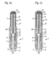
- FIG. 1a a first embodiment of a glow plug in longitudinal section, which contains a resistive element according to the present invention
- FIG. 1b A second embodiment of a glow plug in longitudinal section, which contains a resistive element according to the present invention.
- FIG. 1a shows a longitudinal section through an inventive ceramic resistance element containing embodiment of a glow plug 1.
- a combustion chamber remote end of the glow plug 1 is carried out via an electrical contact via a circular connector 2, which is connected via a seal of a metallic candle housing 4 separately connected to a cylindrical feed line 5.
- the cylindrical feed line 5 is connected via a contact pin 10 and a suitable contacting element 12, preferably as a contact spring, as an electrically conductive Powder pack or as an electrically conductive tablet with an elastic spring portion, preferably made of graphite, is connected to a ceramic glow plug 14.
- the cylindrical feed line 5 can also be combined with the contact pin 10 in one component.
- the interior of the glow plug is sealed by means of a sealing packing 15 with respect to the combustion chamber.
- the sealing packing 15 consists of an electrically conductive carbon compound.
- the sealing packing 15 may also be formed by metals, a mixture of carbon and metal or a mixture of ceramic and metal.
- the glow plug further comprises a resistance element in the form of a glow plug 14, which is formed of a ceramic heating layer 18 and ceramic lead layers 20 and 21, wherein the two lead layers 20, 21 are connected by the heating layer 18 and together with the heating layer 18 form a conductive layer.
- the lead layers 20, 21 have an arbitrary shape; the heating layer 18 can also have any desired shape.
- the conductive layer is U-shaped.
- the lead layers 20, 21 are separated by an insulating layer 22, which is also made of ceramic material.
- the glow plug 14 is designed such that the lead layers 20 and 21 and the heating layer 18 are arranged on the outside of the glow plug 14.
- the lead layers 20 and 21 are located within the glow plug 14 and are still covered by an external, ceramic, insulating layer.
- the ceramic glow plug 14 is isolated by a glass layer, not shown, of the other components of the glow plug 4, 8, 12, 15.
- the glass layer is interrupted at the point 24.
- a further opening of the glass layer at the point 26 allows electrical contact between the feed layer 21 and the plug housing 4 via the sealing packing 15.
- the heating layer 18 was placed at the tip of the glow plug 14 as a preferred embodiment. However, it is also conceivable to place the heating layer 18 at another location of the conductive layer. The heating layer 18 should be at the point where the greatest heating effect is to be achieved.
- the material of the heating layer 18 is chosen so that the absolute electrical resistance of the heating layer 18 is greater than the absolute electrical resistance of the lead layers 20, 21.
- the resistance of the insulating layer 22 is preferably significantly greater than the resistance of the heating layer 18 and the lead layers 20, 21.
- the specific resistance of the insulating layer 22 is at least 10 times greater than the specific resistance of the heating layer 18 over the entire operating range of the glow plug.
- compositions of the insulating layer, the lead layers and the heating layer are chosen in the above-mentioned embodiments so that their thermal expansion coefficients and the shrinkage occurring during the sintering or pyrolysis process of the individual supply, heating and insulating layers are as equal as possible, so that no Cracks in the glow plug arise.
- the heating layer 18 is made of an electrically conductive ceramic having a high electrical resistance.
- This is preferably a ceramic resistor based on an organosilicon polymer provided with fillers, such as, for example, a polysiloxane or a polysilsesquioxane.
- a polysiloxane for example, a condensation-crosslinked polyalkoxysiloxane or an addition-crosslinking polysiloxane such as a methyl-phenyl-vinyl-polysiloxane is used.
- Other polymers such as polycarbosilanes and polysilanes may be added to the polysiloxanes used.
- suitable fillers are molybdenum disilicide, chromium disilicide, iron powder, silicon nitride, silicon powder, titanium silicide, cerium oxide, bismuth oxide, barium oxide, silicon carbide, boron carbide, boron nitride or graphite and optionally also carbon nanotubes or aluminum oxide.
- the feed layers 20, 21 can be embodied in a similar manner, wherein their electrical resistance can be modified, for example, by adding electrically conductive fillers.
- a coating 28 is preferably provided on the combustion chamber exposed ceramic outer surfaces of the glow plug, which is catalytically active and allows burning of accumulating soot particles at low temperatures.
- This coating contains as main components copper, cerium or vanadium or mixtures thereof.
- a total content of compounds of copper, cerium or vanadium of more than 85% by weight, in particular more than 90% by weight, is advantageous.
- said elements copper, cerium and vanadium are contained in the coating 28 as oxides, wherein cerium is preferably present as CeO 2 and / or Ce 2 O 3 .
- catalytic coating 28 Another advantage of the catalytic coating 28 is the fact that the ignition temperature of the burned fuel in the combustion chamber is possibly reduced due to the catalytic function of the coating 30, so that the glow plug can be operated at lower temperatures and thus increases their service life.
- the coating 28 may moreover contain up to 20% by weight, in particular up to 10% by weight, of the platinum metals platinum, palladium, rhodium and / or iridium.
- the coating 28 may contain refractory metal oxides, for example of the elements Zr, Ti, Al, Y, Cr or Ca, as well as mixtures thereof, in order to counteract possible aging of the catalytically active components of the coating.
- the layer thickness of the coating 28 is preferably up to 50 .mu.m, in particular 0.5 to 10 microns. It has been found that the coating 28, in particular in the composition described, develops its catalytic action, above all on ceramic substrates which have been produced on the basis of organosilicon polymers.
- the coating 28 may be formed on the ceramic substrate by dissolving a dispersion or solution of the catalytically active substances, e.g. by dipping (dip coating), printing, rolling, impregnation or air pressure or Ulitaschallvernebelung is applied to the surface of the pen and subsequently a heat treatment in air at temperatures of about 500 ° C, especially at 800 to 1300 ° C at a treatment time from 0.25 to 12 h
- FIG. 1b shows a further embodiment of a glow plug according to the invention containing a ceramic resistance element.
- the same reference numerals designate the same component components as in FIG. 1a ,
- glow plug comprises a resistance element in the form of glow plug 14, which has a further coating 30 between the coating 28 and the ceramic substrate in the form of the ceramic layers 18, 20, 21.
- the further coating 30 is formed by a glass or composite layer, which is embodied, for example, gas-tight, alkali-resistant and high-temperature-stable.
- the glass or composite layer 30 contains one or more of the following oxides: celsian, mullite, silica, alumina, and calcia.
- the layer may comprise proportions of sodium or boron.
- the layer thickness of the further coating 30 is preferably up to 20 ⁇ m, in particular 0.5 to 10 ⁇ m.
- the application of the further coating 30 on a glow plug preferably takes place in a similar manner as the production of the coating 28.
- the coatings 28, 30 may cover the glow plug 14 partially or even over the entire surface. It can be provided that the further coating 30 covers the glow plug 14 in a larger surface area than the coating 28. Thus, the further coating 30, the glow plug 14, for example, cover substantially full area, while the coating 28 is provided only in the region of the heating layer 18 is.
- glow plugs with a coating 28 in the region of the heating layer 18 the elements such as Ir, Pt, Y, Ti, Zr, Cr, W, Mn, Fe, Co, Ni, Zn, Ga and others contained without the addition of copper, cerium or vanadium, only at temperatures above 585 ° C show a significant burnup of the deposited carbon black, while copper-containing coatings 28 already at temperatures of 515 ° C caused a noticeable erosion of soot coating, vanadium-containing coatings 28 already at temperatures of 450 ° C and copper and vanadium coatings 28 already at temperatures between 450 ° C and 515 ° C.
- the ceramic resistance element according to the invention is not only suitable as a glow plug for glow plugs in diesel engines, auxiliary and additional heaters, but also for heaters of flame candles or ceramic gas sensors and for high temperature applications.
- ceramic outer surfaces of electrochemical sensor elements for the determination of gases in gas mixtures can also be provided with the described coatings.
Landscapes
- Engineering & Computer Science (AREA)
- Chemical & Material Sciences (AREA)
- Life Sciences & Earth Sciences (AREA)
- Health & Medical Sciences (AREA)
- Physics & Mathematics (AREA)
- General Health & Medical Sciences (AREA)
- Chemical Kinetics & Catalysis (AREA)
- Electrochemistry (AREA)
- Ceramic Engineering (AREA)
- Analytical Chemistry (AREA)
- Biochemistry (AREA)
- Molecular Biology (AREA)
- General Physics & Mathematics (AREA)
- Immunology (AREA)
- Pathology (AREA)
- Combustion & Propulsion (AREA)
- Mechanical Engineering (AREA)
- General Engineering & Computer Science (AREA)
- Resistance Heating (AREA)
Abstract
Description
- Die Erfindung bezieht sich auf eine keramische Glühstiftkerze nach dem Oberbegriff des Anspruchs 1.
- Aus der
EP 412 428 B1 - Wird ein keramisches Widerstandselement beispielsweise als Heizelement in Glühstiftkerzen eingesetzt, so besteht die Gefahr, dass sich beispielsweise bei nicht optimierter Verbrennung Rußablagerungen am Glühstift bilden (Verkokung). Diese Verkokung kann eine spätere Demontage der Glühstiftkerze erschweren. Ist der außen liegende Teil der keramischen Glühstiftkerze elektrisch leitfähig, so können Rußablagerungen eine Leiterbahn zum Gehäuse ausbilden, wodurch die Glühstiftkerze ggf. nicht mehr korrekt betrieben werden kann bzw. integrierte Sensorfunktionen der Glühstiftkerze (wie z.B. lonenstrommessung) nicht mehr gewährleistet sind.
- Weiterhin ist aus
US 2002/0063118 A1 eine keramische Glühstiftkerze mit einem keramischen Substrat bekannt, das mit eine Schutzschicht aus einer Siliziumkeramik mit darin enthaltenen Seltenerdoxiden versehen ist, wobei als Seltenerdoxide die des Ytterbium, des Lanthan oder des Yttrium eingesetzt werden. Mit den Seltenerdoxiden wird beabsichtigt, das Entstehen von Sulfaten aufgrund von Verunreinigungen zu verhindern, welche den Schmelzpunkt der Keramik herabsetzen können. - Aufgabe der vorliegenden Erfindung ist es, eine keramische Glühstiftkerze bereitzustellen, die Langzeitanwendungen bei höheren Temperaturen standhält.
- Die der Erfindung zugrunde liegende Aufgabe wird dadurch gelöst, dass das keramische Substrat der keramischen Glühstiftkerze mit einer Beschichtung versehen ist, die Kupfer, Cer und/oder Vanadium enthält, wobei der Gesamtgehalt an Verbindungen des Kupfers, Cer bzw. Vanadium mehr als 85 Gew.% beträgt.
- Um die keramische Glühstiftkerze gegenüber einer Verkokung zumindest weitgehend resistent zu gestalten, ist die Beschichtung so ausgeführt, dass ein Abbrand von angelagertem Ruß auch bei moderaten Temperaturen ermöglicht wird, wie sie bspw. bei Verbrennungsprozessen im Brennraum herrschen können. Auf diese Weise wird wirksam verhindert, dass sich leitende Strukturen zum Gehäuse der Glühstiftkerze hin bilden. Darüber hinaus kann durch die Beschichtung katalytisch die Entflammungstemperatur des Kraftstoffes herabgesetzt werden, sodass die Glühstiftkerze bereits bei tieferen Temperaturen betrieben werden kann und sich somit deren Lebensdauer erhöht.
- Mit den in den Unteransprüchen aufgeführten Maßnahmen sind vorteilhafte Weiterbildungen der erfindungsgemäßen keramischen Glühstiftkerze möglich.
- So ist es von besonderem Vorteil, wenn der Gehalt an Verbindungen des Kupfers, Cer bzw. Vanadium beispielsweise mehr als 90 Gew.% beträgt. Weiterhin kann die Beschichtung Oxide der Elemente Zirkon, Titan, Aluminium, Yttrium, Chrom und/oder Calcium enthalten. Auf diese Weise werden Beschichtungen erzielt, die aufgrund der zugesetzten Oxide langzeitstabil sind, und die wirksam den Abbrand von abgelagertem Ruß katalysieren.
- Darüber hinaus kann die Beschichtung bis zu 10 Gew.% der Elemente Platin, Palladium und/oder Rhodium umfassen. Auf diese Weise lässt sich die Beschichtung auf das konkrete Anwendungsgebiet der keramischen Glühstiftkerze ausrichten.
- Weiterhin ist von Vorteil, wenn das keramische Substrat der keramischen Glühstiftkerze eine durch Pyrolyse eines siliciumorganischen Polymers erzeugte Keramik umfasst, da die katalytische Aktivität der Beschichtung auf der dabei resultierenden SiOC-Keramik besonders ausgeprägt ist.
- In einer besonders vorteilhaften Ausführungsform der vorliegenden Erfindung ist zwischen der Beschichtung und dem keramischen Substrat eine weitere Beschichtung vorgesehen, die glasartig oder teilkristallin ausgeführt ist. Diese Beschichtung dient insbesondere dem Schutz der Keramik vor den korrosiven Einflüssen, wie sie beispielsweise bei der Einwirkung von Abgasen von Verbrennungsmotoren auftreten können.
- Zwei Ausführungsbeispiele der Erfindung sind in der Zeichnung dargestellt und in der nachfolgenden Beschreibung näher erläutert. Es zeigt
Figur 1a ein erstes Ausführungsbeispiel einer Glühstiftkerze im Längsschnitt, die ein Widerstandselement gemäß vorliegender Erfindung enthält undFigur 1b ein zweites Ausführungsbeispiel einer Glühstiftkerze im Längsschnitt, die ein Widerstandselement gemäß vorliegender Erfindung enthält. -
Figur 1a zeigt einen Längsschnitt durch eine ein erfindungsgemäßes keramisches Widerstandselement enthaltende Ausführungsform einer Glühstiftkerze 1. An einem brennraumfernen Ende der Glühstiftkerze 1 erfolgt über eine elektrische Kontaktierung über einen Rundstecker 2, der über eine Dichtung von einem metallischen Kerzengehäuse 4 getrennt mit einer zylinderförmigen Zuleitung 5 verbunden ist. Die Fixierung der zylindrischen Zuleitung 5 im Kerzengehäuse 4 erfolgt über einen Metallring 7 und eine elektrisch isolierende Keramikhülse 8. Die zylinderförmige Zuleitung 5 ist über einen Kontaktstift 10 und ein geeignetes Kontaktierungselement 12, das vorzugsweise als Kontaktfeder, als elektrisch leitfähige Pulverpackung oder als elektrisch leitfähige Tablette mit einem elastischen Federanteil, vorzugsweise aus Graphit, ausgebildet ist, mit einem keramischen Glühstift 14 verbunden. Die zylinderförmige Zuleitung 5 kann auch mit dem Kontaktstift 10 in einem Bauteil vereinigt sein. Das Innere der Glühstiftkerze wird mittels einer Dichtpackung 15 gegenüber dem Brennraum abgedichtet. Die Dichtpackung 15 besteht aus einer elektrisch leitenden Kohlenstoffverbindung. Die Dichtpackung 15 kann aber auch durch Metalle, eine Mischung aus Kohlenstoff und Metall oder eine Mischung aus Keramik und Metall ausgebildet sein. - Die Glühstiftkerze umfasst weiterhin ein Widerstandselement in Form eines Glühstifts 14, der aus einer keramischen Heizschicht 18 und keramischen Zuleitungsschichten 20 und 21 gebildet ist, wobei die beiden Zuleitungsschichten 20, 21 durch die Heizschicht 18 verbunden sind und mit der Heizschicht 18 zusammen eine Leitschicht bilden. Die Zuleitungsschichten 20, 21 besitzen eine beliebige Form, auch die Heizschicht 18 kann eine beliebige Form besitzen. Vorzugsweise ist die Leitschicht U-förmig ausgebildet. Die Zuleitungsschichten 20, 21 sind über eine Isolationsschicht 22, die ebenfalls aus keramischem Material besteht, voneinander getrennt. In dem in
Figur 1 dargestellten Ausführungsbeispiel ist der Glühstift 14 derart gestaltet, dass die Zuleitungsschichten 20 und 21 sowie die Heizschicht 18 auf der Außenseite des Glühstifts 14 angeordnet sind. Es ist jedoch auch möglich, zumindest die Zuleitungsschichten 20 und 21 so anzuordnen, dass sie sich innerhalb des Glühstiftes 14 befinden und noch von einer außen liegenden, keramischen, isolierenden Schicht bedeckt werden. Innerhalb des Kerzengehäuses 4 ist der keramische Glühstift 14 durch eine nicht dargestellte Glasschicht von den übrigen Bestandteilen der Glühstiftkerze 4, 8, 12, 15 isoliert. - Um den elektrischen Kontakt zwischen dem Kontaktierungselement 12 und der Zuleitungsschicht 20 herzustellen, ist die Glasschicht an der Stelle 24 unterbrochen. Eine weitere Durchbrechung der Glasschicht an der Stelle 26 ermöglicht einen elektrischen Kontakt zwischen Zuleitungsschicht 21 und Kerzengehäuse 4 über die Dichtpackung 15. In diesem Ausführungsbeispiel wurde als bevorzugte Ausführungsform die Heizschicht 18 an der Spitze des Glühstiftes 14 platziert. Es ist jedoch auch denkbar, die Heizschicht 18 an einer anderen Stelle der Leitschicht zu platzieren. Die Heizschicht 18 sollte sich an der Stelle befinden, an der die größte Heizwirkung erzielt werden soll.
- Das Material der Heizschicht 18 wird so gewählt, dass der absolute elektrische Widerstand der Heizschicht 18 größer ist als der absolute elektrische Widerstand der Zuleitungsschichten 20, 21. Um Querströme zwischen den Komponenten der Leitschicht zu vermeiden, ist der Widerstand der Isolationsschicht 22 vorzugsweise deutlich größer als der Widerstand der Heizschicht 18 und der Zuleitungsschichten 20, 21.
- In einem bevorzugten Ausführungsbeispiel ist der spezifische Widerstand der Isolationsschicht 22 im gesamten Betriebsbereich der Glühstiftkerze mindestens 10 mal größer als der spezifische Widerstand der Heizschicht 18.
- Die Zusammensetzungen der Isolationsschicht, der Zuleitungsschichten und der Heizschicht werden in den oben angegebenen Ausführungsbeispielen so gewählt, dass ihre thermischen Ausdehnungskoeffizienten und die während des Sinter- bzw. Pyrolyseprozesses auftretenden Schrumpfungen der einzelnen Zuleitungs-, Heiz- und Isolationsschichten möglichst gleich sind, so dass keine Risse im Glühstift entstehen.
- Die Heizschicht 18 ist aus einer elektrisch leitfähigen Keramik mit einem hohen elektrischen Widerstand ausgeführt. Dabei handelt es sich vorzugsweise um einen keramischen Widerstand auf der Basis eines mit Füllstoffen versehenen siliciumorganischen Polymers, wie beispielsweise eines Polysiloxans oder eines Polysilsesquioxans. Als Polysiloxan wird beispielsweise ein kondensationsvernetztes Polyalkoxysiloxan oder ein additionsvemetzendes Polysiloxan wie beispielsweise ein Methyl-Phenyl-Vinyl-Polysiloxan verwendet. Den verwendeten Polysiloxanen können weitere Polymere wie beispielsweise Polycarbosilane und Polysilane zugesetzt werden. Diese können in einem geeigneten Lösungsmittel wie beispielsweise Aceton oder Tetrahydrofuran gelöst und mit geeigneten Füllstoffen versetzt werden. Über die Auswahl und Zugabemenge eines oder mehrerer geeigneter Füllstoffe kann der elektrische Widerstand der resultierenden Keramik gezielt eingestellt werden. Geeignete Füllstoffe sind beispielsweise Molybdändisilicid, Chromdisilicid, Eisenpulver, Siliciumnitrid, Siliciumpulver, Titansilicid, Ceroxid, Bismuthoxid, Bariumoxid, Siliciumcarbid, Borcarbid, Bornitrid oder Graphit sowie ggf. auch Kohlenstoffnanoröhren oder Aluminiumoxid. Die Zuleitungsschichten 20,21 können in ähnlicher Weise ausgeführt werden, wobei deren elektrischer Widerstand beispielsweise durch Zusatz elektrisch leitfähiger Füllstoffe modifiziert werden kann.
- Vor allem im Bereich der Heizschicht 18 besteht die Gefahr, dass es bedingt durch die im Brennraum ablaufenden Verbrennungsprozesse zu einer unerwünschten Verkokung der keramischen Oberfläche des Glühstiftes 14 kommt. Diese Gefahr besteht insbesondere dann, wenn der Glühstift nicht angesteuert wird oder die Verbrennungsprozesse nicht im Bereich eines optimalen Umsatzes stattfinden. Diese Verkokung kann eine spätere Demontage des Glühstiftes erschweren. Ist der außen liegende Teil des keramischen Glühstiftes elektrisch leitfähig, so können die Ablagerungen eine Leiterbahn zum Gehäuse ausbilden, wodurch ein korrekter Betrieb des Glühstifts beeinträchtigt werden kann bzw. integrierte Sensorfunktionen der Glühstiftkerze (wie z.B. eine Ionenstrommessung) nicht mehr gewährleistet sind.
- Daher ist vorzugsweise auf den dem Verbrennungsraum ausgesetzten keramischen Außenflächen des Glühstifts eine Beschichtung 28 vorgesehen, die katalytisch aktiv ist und einen Abbrand sich anlagernder Rußpartikel bei niedrigen Temperaturen ermöglicht. Diese Beschichtung enthält als Hauptkomponenten Kupfer, Cer oder Vanadium bzw. Mischungen derselben. Dabei ist insbesondere ein Gesamtgehalt an Verbindungen des Kupfers, Cers bzw. Vanadium von mehr als 85 Gew.%, insbesondere mehr als 90 Gew.% von Vorteil. Vorzugsweise sind die genannten Elemente Kupfer, Cer und Vanadium in der Beschichtung 28 als Oxide enthalten, wobei Cer vorzugsweise als CeO2 und/oder Ce2O3 vorliegt.
- Ein weiterer Vorteil der katalytischen Beschichtung 28 ist darin zu sehen, dass die Entflammungstemperatur des im Verbrennungsraum verbrannten Kraftstoffes bedingt durch die katalytische Funktion der Beschichtung 30 ggf. herabgesetzt wird, sodass die Glühstiftkerze bei tieferen Temperaturen betrieben werden kann und sich somit deren Lebensdauer erhöht.
- Die Beschichtung 28 kann darüber hinaus bis zu 20 Gew.%, insbesondere bis zu 10 Gew.% der Platinmetalle Platin, Palladium, Rhodium und/oder Iridium enthalten.
- Weiterhin kann die Beschichtung 28 hochschmelzende Metalloxide beispielsweise der Elemente Zr, Ti, Al, Y, Cr oder Ca sowie Mischungen derselben enthalten, um einer möglichen Alterung der katalytisch aktiven Komponenten der Beschichtung entgegenzuwirken.
- Die Schichtdicke der Beschichtung 28 beträgt vorzugsweise bis zu 50 µm, insbesondere 0,5 bis 10 µm. Es hat sich herausgestellt, dass die Beschichtung 28 insbesondere in der beschriebenen Zusammensetzung ihre katalytische Wirkung vor allem auf keramischen Substraten entwickelt, die auf der Basis siliciumorganischer Polymere hergestellt wurden.
- Die Beschichtung 28 kann auf dem keramischen Substrat erzeugt werden, indem eine Dispersion oder Lösung der katalytisch aktiven Substanzen z.B. mittels Eintauchen (dip coating), Aufdrucken, Aufrollen, Imprägnieren oder durch Luftdruck- bzw. Ulitraschallvernebelung auf die Oberfläche des Stiftes aufgebracht wird und nachfolgend eine Wärmebehandlung an Luft bei Temperaturen von über 500°C, insbesondere bei 800 bis 1300°C bei einer Behandlungszeit von 0,25 bis 12 h unterzogen wird
-
Figur 1b zeigt ein weiteres Ausführungsbeispiel einer ein erfindungsgemäßes keramisches Widerstandselement enthaltenden Glühstiftkerze. Dabei bezeichnen gleiche Bezugszeichen gleiche Bauteilkomponenten wie inFigur 1a . - Die in
Figur 1b dargestellte Glühstiftkerze umfasst ein Widerstandelement in Form des Glühstifts 14, der zwischen der Beschichtung 28 und dem keramischen Substrat in Form der keramischen Schichten 18, 20, 21 eine weitere Beschichtung 30 aufweist. Die weitere Beschichtung 30 wird durch eine Glas- bzw. Kompositschicht gebildet, die beispielsweise gasdicht, alkaliresistent und hochtemperaturstabil ausgeführt ist. Die Glas- bzw. Kompositschicht 30 enthält eine oder mehrere der folgenden Oxide Celsian, Mullit, Siliciumdioxid, Aluminiumoxid, und Calciumoxid. Zusätzlich kann die Schicht Anteile von Natrium oder Bor aufweisen. Die Schichtdicke der weiteren Beschichtung 30 beträgt vorzugsweise bis zu 20 µm, insbesondere 0,5 bis 10 µm. Die Aufbringung der weiteren Beschichtung 30 auf einer Glühstiftkerze erfolgt vorzugsweise auf eine ähnliche Art und Weise wie die Erzeugung der Beschichtung 28. - Die Beschichtungen 28, 30 können den Glühstift 14 teil- oder auch vollflächig bedecken. Dabei kann vorgesehen sein, dass die weitere Beschichtung 30 den Glühstift 14 in einem größeren Oberflächenbereich bedeckt als die Beschichtung 28. So kann die weitere Beschichtung 30 den Glühstift 14 beispielsweise im wesentlichen vollflächig bedecken, während hingegen die Beschichtung 28 lediglich im Bereich der Heizschicht 18 vorgesehen ist.
- Werden beschichtete Glühstiftkerzen einem Langzeittest unterzogen, so zeigt sich, dass Glühstiftkerzen mit einer Beschichtung 28 im Bereich der Heizschicht 18, die Elemente wie bspw. Ir, Pt, Y, Ti, Zr, Cr, W, Mn, Fe, Co, Ni, Zn, Ga und andere ohne Zusatz von Kupfer, Cer oder Vanadium enthielten, erst bei Temperaturen über 585°C einen nennenswerten Abbrand des angelagerten Rußes zeigen, während kupferhaltige Beschichtungen 28 bereits bei Temperaturen von 515°C einen merklichen Abbrand der Rußbeschichtung bewirkten, vanadiumhaltige Beschichtungen 28 bereits bei Temperaturen von 450°C und kupfer- sowie vanadiumhaltige Beschichtungen 28 bereits bei Temperaturen zwischen 450°C und 515°C.
- Das erfindungsgemäße keramische Widerstandselement ist nicht nur als Glühstift für Glühstiftkerzen in Dieselmotoren, Stand- und Zusatzheizungen geeignet, sondern auch für Heizvorrichtungen von Flammkerzen oder keramischen Gassensoren sowie für Hochtemperaturanwendungen. Insbesondere können auch keramische Außenflächen von elektrochemischen Sensorelementen zur Bestimmung von Gasen in Gasgemischen mit den beschriebenen Beschichtungen versehen sein.
Claims (11)
- Glühstiftkerze mit einem keramischen Substrat (18, 20, 21), welche einer Gasatmosphäre aussetzbar ist, die Kohlenstoffverbindungen enthält, wobei das keramische Substrat (18, 20, 21) mit einer Beschichtung (28) versehen ist, dadurch gekennzeichnet, dass die Beschichtung (28) Kupfer, Cer und/oder Vanadium enthält, und dass der Gesamtgehalt an Verbindungen des Kupfers, Cers bzw. Vanadium mehr als 85 Gew.% beträgt.
- Glühstiftkerze nach Anspruch 1, dadurch gekennzeichnet, dass die Beschichtung (28) zu über 90 Gew.% durch Verbindungen des Kupfers, Cers und/oder Vanadium gebildet ist.
- Glühstiftkerze nach Anspruch 1 oder 2, dadurch gekennzeichnet, dass die Beschichtung (28) weiterhin Oxide der Elemente Zirkon, Titan, Aluminium, Yttrium, Chrom und/oder Calcium enthält.
- Glühstiftkerze nach Anspruch 1, 2 oder 3, dadurch gekennzeichnet, dass die Beschichtung (28) zusätzlich bis zu 10 Gew.% der Elemente Platin, Palladium und/oder Rhodium enthält.
- Glühstiftkerze nach einem der Ansprüche 1 bis 4, dadurch gekennzeichnet, dass die Beschichtung (28) Cer in Form von CeO2 und/oder Ce2O3 enthält.
- Glühstiftkerze nach einem der vorhergehenden Ansprüche, dadurch gekennzeichnet, dass die Beschichtung (28) eine Schichtdicke von 0.5 bis 50 µm aufweist.
- Glühstiftkerze nach einem der vorhergehenden Ansprüche, dadurch gekennzeichnet, dass das Substrat (18, 20, 21) eine durch Pyrolyse eines siliciumorganischen Polymers erzeugte Keramik umfasst.
- Glühstiftkerze nach einem der vorhergehenden Ansprüche, dadurch gekennzeichnet, dass das Substrat (18, 20, 21) Siliciumnitrid umfasst.
- Glühstiftkerze nach einem der vorhergehenden Ansprüche, dadurch gekennzeichnet, dass das Substrat als Füllstoff Siliciumcarbid, Molybdändisilicid, Chromdisilicid, Molybdäncarbid, Eisen, Silicium, Aluminiumoxid und/oder Graphit enthält.
- Glühstiftkerze nach einem der vorhergehenden Ansprüche, dadurch gekennzeichnet, dass zwischen der Beschichtung (28) und dem keramischen Substrat (18, 20, 21) eine weitere Beschichtung (30) vorgesehen ist, die glasartig oder teilkristallin ausgeführt ist.
- Glühstiftkerze nach einem der vorhergehenden Ansprüche, dadurch gekennzeichnet, dass die weitere Beschichtung (30) Mullit, Celsian, Siliciumdioxid, Aluminiumdioxid oder Calciumoxid enthält.
Applications Claiming Priority (2)
| Application Number | Priority Date | Filing Date | Title |
|---|---|---|---|
| DE102005015569A DE102005015569A1 (de) | 2005-04-05 | 2005-04-05 | Keramisches Widerstands- oder Sensorelement |
| PCT/EP2006/061029 WO2006106047A1 (de) | 2005-04-05 | 2006-03-24 | Keramisches widerstands- oder sensorelement |
Publications (2)
| Publication Number | Publication Date |
|---|---|
| EP1868962A1 EP1868962A1 (de) | 2007-12-26 |
| EP1868962B1 true EP1868962B1 (de) | 2010-11-24 |
Family
ID=36282901
Family Applications (1)
| Application Number | Title | Priority Date | Filing Date |
|---|---|---|---|
| EP06725299A Ceased EP1868962B1 (de) | 2005-04-05 | 2006-03-24 | Keramische glühstiftkerze |
Country Status (4)
| Country | Link |
|---|---|
| US (1) | US20090169900A1 (de) |
| EP (1) | EP1868962B1 (de) |
| DE (2) | DE102005015569A1 (de) |
| WO (1) | WO2006106047A1 (de) |
Families Citing this family (7)
| Publication number | Priority date | Publication date | Assignee | Title |
|---|---|---|---|---|
| DE102007044967A1 (de) * | 2007-09-19 | 2009-04-02 | Beru Ag | Glühkerze mit verkokungsoptimiertem Design, spezielle Ringspaltausbildung |
| DE102008002436A1 (de) | 2008-06-16 | 2009-12-17 | Robert Bosch Gmbh | Verfahren zur Herstellung eines keramischen Schichtverbundes |
| DE102008043228A1 (de) * | 2008-10-28 | 2010-04-29 | Hilti Aktiengesellschaft | Brennkraftbetriebenes Setzgerät |
| JP5763494B2 (ja) | 2011-09-30 | 2015-08-12 | 日本特殊陶業株式会社 | 潤滑塗料組成物及び内燃機関用取付部品 |
| DE102012110845A1 (de) * | 2012-11-12 | 2014-05-15 | Epcos Ag | Temperaturfühler und Verfahren zur Herstellung eines Temperaturfühlers |
| JP6059170B2 (ja) * | 2013-04-30 | 2017-01-11 | 日本特殊陶業株式会社 | 温度センサ |
| DE102013219266A1 (de) * | 2013-09-25 | 2015-03-26 | Robert Bosch Gmbh | Glühstiftkerze mit integriertem Drucksensor |
Family Cites Families (18)
| Publication number | Priority date | Publication date | Assignee | Title |
|---|---|---|---|---|
| DE3028188A1 (de) * | 1980-07-25 | 1982-02-25 | Robert Bosch Gmbh, 7000 Stuttgart | Sensor |
| DE3706576A1 (de) * | 1987-02-28 | 1988-09-08 | Bosch Gmbh Robert | Zuendanordnung mit herabgesetzter zuendtemperatur |
| US5084606A (en) * | 1990-05-17 | 1992-01-28 | Caterpillar Inc. | Encapsulated heating filament for glow plug |
| DE4100915A1 (de) * | 1991-01-15 | 1992-07-16 | Bosch Gmbh Robert | Sensor fuer die bestimmung von kohlenmonoxid |
| US5304778A (en) * | 1992-11-23 | 1994-04-19 | Electrofuel Manufacturing Co. | Glow plug with improved composite sintered silicon nitride ceramic heater |
| DE4333232B4 (de) * | 1993-09-30 | 2004-07-01 | Robert Bosch Gmbh | Meßfühler zur Bestimmung des Sauerstoffgehaltes von Gasgemischen |
| DE4334672C2 (de) * | 1993-10-12 | 1996-01-11 | Bosch Gmbh Robert | Sensor zum Nachweis von Stickoxid |
| ES2131335T3 (es) * | 1994-10-19 | 1999-07-16 | Bosch Gmbh Robert | Resistencia ceramica electrica y su empleo. |
| DE19542944C2 (de) * | 1995-11-17 | 1998-01-22 | Daimler Benz Ag | Brennkraftmaschine und Verfahren zum Aufbringen einer Wärmedämmschicht |
| US5578349A (en) * | 1995-11-30 | 1996-11-26 | Caterpillar Inc. | Process for coating a ceramic glow plug portion with a corrosion inhibiting material |
| DE19623212A1 (de) * | 1996-06-11 | 1997-12-18 | Bosch Gmbh Robert | Sensor zur Bestimmung der Konzentration oxidierbarer Bestandteile in einem Gasgemisch |
| DE19623434A1 (de) * | 1996-06-12 | 1997-12-18 | Bosch Gmbh Robert | Sensor zur Bestimmung der Konzentration oxidierbarer Bestandteile in einem Gasgemisch |
| DE19647268C1 (de) * | 1996-11-15 | 1998-05-07 | Bosch Gmbh Robert | Sensor zur Bestimmung der Konzentration oxidierbarer Bestandteile in einem Gasgemisch |
| DE19734861C2 (de) * | 1997-08-12 | 1999-10-28 | Bosch Gmbh Robert | Sensorelement zur Bestimmung der Konzentration oxidierbarer Bestandteile in einem Gasgemisch |
| GB2355005B (en) * | 1999-10-04 | 2004-03-24 | Caterpillar Inc | Rare earth silicate coating on a silicon-based ceramic component by controlled oxidation for improved corrosion resistance |
| DE10144271A1 (de) * | 2001-09-08 | 2003-03-27 | Bosch Gmbh Robert | Sensorelement zur Erfassung einer physikalischen Messgröße zwischen tribologisch hoch beanspruchten Körpern |
| DE10147408B4 (de) * | 2001-09-26 | 2012-03-01 | Robert Bosch Gmbh | Gassensor zur Erfassung von Gasbestandteilen eines Gasstroms |
| DE10315593B4 (de) * | 2003-04-05 | 2005-12-22 | Daimlerchrysler Ag | Abgasnachbehandlungseinrichtung und -verfahren |
-
2005
- 2005-04-05 DE DE102005015569A patent/DE102005015569A1/de not_active Withdrawn
-
2006
- 2006-03-24 US US11/918,026 patent/US20090169900A1/en not_active Abandoned
- 2006-03-24 DE DE502006008386T patent/DE502006008386D1/de active Active
- 2006-03-24 EP EP06725299A patent/EP1868962B1/de not_active Ceased
- 2006-03-24 WO PCT/EP2006/061029 patent/WO2006106047A1/de active Application Filing
Also Published As
| Publication number | Publication date |
|---|---|
| EP1868962A1 (de) | 2007-12-26 |
| US20090169900A1 (en) | 2009-07-02 |
| DE102005015569A1 (de) | 2006-10-12 |
| WO2006106047A1 (de) | 2006-10-12 |
| DE502006008386D1 (de) | 2011-01-05 |
Similar Documents
| Publication | Publication Date | Title |
|---|---|---|
| EP1868962B1 (de) | Keramische glühstiftkerze | |
| DE102007046900C5 (de) | Hochtemperatursensor und ein Verfahren zu dessen Herstellung | |
| DE68927087T2 (de) | Sauerstoffempfindlicher Sensor und Verfahren zu dessen Herstellung | |
| DE4433505C2 (de) | Keramikglühkerze | |
| EP2953217B1 (de) | Verfahren zur herstellung einer zündkerze für einen verbrennungsmotor sowie zündkerze für einen verbrennungsmotor | |
| DE2643131A1 (de) | Elektrisch leitende verbundkeramik und verfahren zu deren herstellung | |
| DE10124373A1 (de) | Temperaturfühler und Verfahren zur Steuerung von dessen Herstellung | |
| EP2197813B1 (de) | Keramischer schichtverbund | |
| KR920000219B1 (ko) | 점화 및 가열기구용 도전성 세르메트조성물 및 그의 제조방법 | |
| WO2002002933A1 (de) | Glühstiftkerze mit ionenstromsensor sowie verfahren zum betreiben einer derartigen glühstiftkerze | |
| DE102019001514A1 (de) | Sensorelement und Gassensor | |
| DE3843863C2 (de) | ||
| DE102008002436A1 (de) | Verfahren zur Herstellung eines keramischen Schichtverbundes | |
| EP1875570A1 (de) | Elektrode für eine zündkerze | |
| EP1145255A2 (de) | Heizleiter, insbesondere für einen messfühler, und ein verfahren zur herstellung des heizleiters | |
| DE10348778B3 (de) | Elektrode für eine Zündkerze und Verfahren zum Herstellen einer Elektrode | |
| EP1299676A1 (de) | Glühstiftkerze mit ionenstromsensor sowie verfahren zum betreiben einer derartigen glühstiftkerze | |
| DE102014210926B3 (de) | Verfahren zur Herstellung einer Zündkerze für einen Verbrennungsmotor sowie Zündkerze für einen Verbrennungsmotor | |
| DE4221786C2 (de) | Temperaturfeste Keramik | |
| DE19708105C2 (de) | Keramische Zusammensetzung, Verfahren zu deren Herstellung sowie deren Verwendung | |
| EP0487652B1 (de) | Elektrochemischer messfühler | |
| WO2006018347A1 (de) | Keramischer elektrischer widerstand | |
| DE102005024622B4 (de) | Stabglühkerze | |
| DE102005060660A1 (de) | Keramischer Widerstand und Grünkörper zu dessen Herstellung | |
| DE19939319B4 (de) | Zündkerze für eine Brennkraftmaschine |
Legal Events
| Date | Code | Title | Description |
|---|---|---|---|
| PUAI | Public reference made under article 153(3) epc to a published international application that has entered the european phase |
Free format text: ORIGINAL CODE: 0009012 |
|
| 17P | Request for examination filed |
Effective date: 20071105 |
|
| AK | Designated contracting states |
Kind code of ref document: A1 Designated state(s): DE FR IT |
|
| DAX | Request for extension of the european patent (deleted) | ||
| RBV | Designated contracting states (corrected) |
Designated state(s): DE FR IT |
|
| 17Q | First examination report despatched |
Effective date: 20091030 |
|
| GRAP | Despatch of communication of intention to grant a patent |
Free format text: ORIGINAL CODE: EPIDOSNIGR1 |
|
| RTI1 | Title (correction) |
Free format text: CERAMIC GLOW PLUG |
|
| GRAS | Grant fee paid |
Free format text: ORIGINAL CODE: EPIDOSNIGR3 |
|
| GRAA | (expected) grant |
Free format text: ORIGINAL CODE: 0009210 |
|
| AK | Designated contracting states |
Kind code of ref document: B1 Designated state(s): DE FR IT |
|
| REF | Corresponds to: |
Ref document number: 502006008386 Country of ref document: DE Date of ref document: 20110105 Kind code of ref document: P |
|
| PLBE | No opposition filed within time limit |
Free format text: ORIGINAL CODE: 0009261 |
|
| STAA | Information on the status of an ep patent application or granted ep patent |
Free format text: STATUS: NO OPPOSITION FILED WITHIN TIME LIMIT |
|
| 26N | No opposition filed |
Effective date: 20110825 |
|
| REG | Reference to a national code |
Ref country code: DE Ref legal event code: R097 Ref document number: 502006008386 Country of ref document: DE Effective date: 20110825 |
|
| PGFP | Annual fee paid to national office [announced via postgrant information from national office to epo] |
Ref country code: IT Payment date: 20140325 Year of fee payment: 9 |
|
| PG25 | Lapsed in a contracting state [announced via postgrant information from national office to epo] |
Ref country code: IT Free format text: LAPSE BECAUSE OF NON-PAYMENT OF DUE FEES Effective date: 20150324 |
|
| REG | Reference to a national code |
Ref country code: FR Ref legal event code: PLFP Year of fee payment: 11 |
|
| REG | Reference to a national code |
Ref country code: FR Ref legal event code: PLFP Year of fee payment: 12 |
|
| PGFP | Annual fee paid to national office [announced via postgrant information from national office to epo] |
Ref country code: FR Payment date: 20170323 Year of fee payment: 12 |
|
| PGFP | Annual fee paid to national office [announced via postgrant information from national office to epo] |
Ref country code: DE Payment date: 20170529 Year of fee payment: 12 |
|
| REG | Reference to a national code |
Ref country code: DE Ref legal event code: R119 Ref document number: 502006008386 Country of ref document: DE |
|
| PG25 | Lapsed in a contracting state [announced via postgrant information from national office to epo] |
Ref country code: DE Free format text: LAPSE BECAUSE OF NON-PAYMENT OF DUE FEES Effective date: 20181002 |
|
| PG25 | Lapsed in a contracting state [announced via postgrant information from national office to epo] |
Ref country code: FR Free format text: LAPSE BECAUSE OF NON-PAYMENT OF DUE FEES Effective date: 20180331 |