EP1867594B1 - Aufzugssystem und betriebssteuerungsverfahren dafür - Google Patents
Aufzugssystem und betriebssteuerungsverfahren dafür Download PDFInfo
- Publication number
- EP1867594B1 EP1867594B1 EP06730102.8A EP06730102A EP1867594B1 EP 1867594 B1 EP1867594 B1 EP 1867594B1 EP 06730102 A EP06730102 A EP 06730102A EP 1867594 B1 EP1867594 B1 EP 1867594B1
- Authority
- EP
- European Patent Office
- Prior art keywords
- elevator system
- elevator
- power source
- control apparatus
- operating
- Prior art date
- Legal status (The legal status is an assumption and is not a legal conclusion. Google has not performed a legal analysis and makes no representation as to the accuracy of the status listed.)
- Ceased
Links
Images


Classifications
-
- B—PERFORMING OPERATIONS; TRANSPORTING
- B66—HOISTING; LIFTING; HAULING
- B66B—ELEVATORS; ESCALATORS OR MOVING WALKWAYS
- B66B5/00—Applications of checking, fault-correcting, or safety devices in elevators
- B66B5/02—Applications of checking, fault-correcting, or safety devices in elevators responsive to abnormal operating conditions
- B66B5/021—Applications of checking, fault-correcting, or safety devices in elevators responsive to abnormal operating conditions the abnormal operating conditions being independent of the system
- B66B5/022—Applications of checking, fault-correcting, or safety devices in elevators responsive to abnormal operating conditions the abnormal operating conditions being independent of the system where the abnormal operating condition is caused by a natural event, e.g. earthquake
-
- B—PERFORMING OPERATIONS; TRANSPORTING
- B66—HOISTING; LIFTING; HAULING
- B66B—ELEVATORS; ESCALATORS OR MOVING WALKWAYS
- B66B1/00—Control systems of elevators in general
- B66B1/34—Details, e.g. call counting devices, data transmission from car to control system, devices giving information to the control system
-
- B—PERFORMING OPERATIONS; TRANSPORTING
- B66—HOISTING; LIFTING; HAULING
- B66B—ELEVATORS; ESCALATORS OR MOVING WALKWAYS
- B66B1/00—Control systems of elevators in general
- B66B1/02—Control systems without regulation, i.e. without retroactive action
- B66B1/06—Control systems without regulation, i.e. without retroactive action electric
-
- B—PERFORMING OPERATIONS; TRANSPORTING
- B66—HOISTING; LIFTING; HAULING
- B66B—ELEVATORS; ESCALATORS OR MOVING WALKWAYS
- B66B5/00—Applications of checking, fault-correcting, or safety devices in elevators
- B66B5/02—Applications of checking, fault-correcting, or safety devices in elevators responsive to abnormal operating conditions
- B66B5/021—Applications of checking, fault-correcting, or safety devices in elevators responsive to abnormal operating conditions the abnormal operating conditions being independent of the system
- B66B5/024—Applications of checking, fault-correcting, or safety devices in elevators responsive to abnormal operating conditions the abnormal operating conditions being independent of the system where the abnormal operating condition is caused by an accident, e.g. fire
-
- Y—GENERAL TAGGING OF NEW TECHNOLOGICAL DEVELOPMENTS; GENERAL TAGGING OF CROSS-SECTIONAL TECHNOLOGIES SPANNING OVER SEVERAL SECTIONS OF THE IPC; TECHNICAL SUBJECTS COVERED BY FORMER USPC CROSS-REFERENCE ART COLLECTIONS [XRACs] AND DIGESTS
- Y02—TECHNOLOGIES OR APPLICATIONS FOR MITIGATION OR ADAPTATION AGAINST CLIMATE CHANGE
- Y02B—CLIMATE CHANGE MITIGATION TECHNOLOGIES RELATED TO BUILDINGS, e.g. HOUSING, HOUSE APPLIANCES OR RELATED END-USER APPLICATIONS
- Y02B50/00—Energy efficient technologies in elevators, escalators and moving walkways, e.g. energy saving or recuperation technologies
Definitions
- This invention relates to an elevator system and a running control method therefor, in which the reduction of standby electric power is attained, and more particularly to an elevator system and a running control method therefor, according to which when a power source is restored from a state where the power source has been cut off or a state where an energy saving mode has been selected, the elevator system can be utilized after the confirmation of the state of an external input.
- Patent Document 1 discloses an elevator apparatus that is capable of reducing the downtime of an elevator due to the occurrence of an earthquake. Thereby, the system distinguishes between different magnitudes of the earthquake. For small and moderate earthquakes, the system is capable of resuming the operation of the elevator system either autonomously or upon external input. Before resuming the normal operation, the system according to Patent Document 2 undergoes several evaluation and waiting steps to ensure that the system was not damaged by the earthquake and is capable of functioning normally.
- Patent Document 1 JP-A-2001-2335 (Sector 0028, Fig. 1 )
- the elevator control apparatus cannot alter an earthquake sensor having operated by sensing the occurrence of the earthquake, from a set state into a reset state because the elevator control apparatus was not operating during the cutoff of the power source. Even when a user performs the manipulation of a request for the power source restoration in this situation with the intention of using the elevator system, the earthquake sensor is held operating in spite of the lapse of a time period since the occurrence of the earthquake, and hence, the elevator control apparatus selects earthquake control running, resulting in such a problem that the elevator system cannot be immediately used.
- the elevator control apparatus cannot recognize the occurrence of the fire because this elevator control apparatus was not operating during the cutoff of the power source. Accordingly, when a user performs the manipulation of a request for the power source restoration in this situation with the intention of using the elevator system, the elevator control apparatus selects fire control running at that point of time in spite of the lapse of a time period since the occurrence of the fire and the spread of the fire, resulting in such a problem that the elevator control apparatus causes a cage to travel to a refuge floor and opens a door.
- This invention has been made in view of the above problems, and it has for its object to provide an elevator system and a running control method therefor, according to which in restoring the power source of the elevator system that is in a state where unnecessary power feed has been cut off in a slack time zone, or the like or in a state where an energy saving mode has been selected, the elevator system can be used after the state of an earthquake sensor operating by sensing an earthquake or a fire control switch operating by recognizing the occurrence of a fire has been confirmed.
- An elevator system consists, in an elevator system including an elevator control apparatus to which an operation signal of an earthquake sensor operating by sensing an earthquake is inputted, wherein in a case where a command for operating the elevator system exists during cutoff of a power source of the elevator system or during selection of an energy saving mode, the power source of the elevator system is restored by the elevator control apparatus in interlocking with the command; in that, when the elevator control apparatus has received the command for operating the elevator system, in a state where the earthquake sensor has operated during the cutoff of the power source of the elevator system or during the selection of the energy saving mode, it resets the earthquake sensor and controls running of the elevator system.
- a running control method for an elevator system consists, in a running control method for an elevator system including an elevator control apparatus to which an operation signal of an earthquake sensor operating by sensing an earthquake is inputted, wherein in a case where a command for operating the elevator system exists during cutoff of a power source of the elevator system or during selection of an energy saving mode, the power source of the elevator system is restored by the elevator control apparatus in interlocking with the command; in comprising a first step of judging if the elevator system is under the cutoff of the power source or under the selection of the energy saving mode; a second step of judging the existence or nonexistence of the command for operating the elevator system, in a case where the elevator system is under the cutoff of the power source or under the selection of the energy saving mode at the first step; a third step of judging existence or nonexistence of the operation of the earthquake sensor, in a case where the command for operating the elevator system exists at the second step; and a fourth step of resetting the earthquake sensor in a case where the earthquake sensor
- the elevator system is subjected to a running control after the state of an earthquake sensor operating by sensing an earthquake or a fire control switch operating by recognizing the occurrence of a fire has been confirmed, to bring forth the advantages that the elevator system is available immediately in compliance with the request for the power source restoration at the occurrence of the earthquake, and that the running of the elevator system is stopped in compliance with the request for the power source restoration at the occurrence of the fire, so service can be enhanced from the viewpoint of keeping safety.
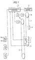
- Fig. 1 is a block diagram showing the general configuration of the elevator system according to Embodiment 1 of this invention.
- a cage 1 which is disposed in vertically movable fashion within a hoistway not shown is provided with a cage manipulation panel 3 in which a cage call button 2 is assembled.
- a signal which is outputted from the cage manipulation panel 3 is inputted to an elevator control apparatus 4 which is mounted in, for example, a machinery room, and the elevator control apparatus 4 is configured so as to perform the running control of the elevator system on the basis of the inputted signal.
- the elevator control apparatus 4 controls through an inverter 6, a winding machine 5 for vertically moving the cage 1.
- a main rope 7 is extended over the drive sheave 5a of the winding machine 5, and one end of the main rope 7 is secured to the cage 1, while the other end is secured to a counterweight 8.
- a governor rope 9 is attached to the cage 1, and this rope 9 is extended over a governor sheave 10.
- the governor sheave 10 is furnished with a rotary encoder 11 for detecting the position and moving direction of the cage 1, in addition to a governor (not shown).
- the cage 1 is provided with passenger-percentage detection means 12 for detecting the passenger percentage of passengers who have gotten in the cage 1. Incidentally, signals which have been outputted from the rotary encoder 11 and the passenger-percentage detection means 12 are inputted to the elevator control apparatus 4 so as to be used for the various controls of the elevator system.
- Each floor is furnished with hall call registrationmeans, for example, hall call buttons 13a and 13b in ascent and descent directions, and when a user wants to go to a floor in the ascent direction, he/she manipulates the hall call button 13a in the ascent direction, while when a user wants to go to a floor in the descent direction, he/she manipulates the hall call button 13b in the descent direction.
- Signals which have been outputted from the hall call button 13a in the ascent direction and the hall call button 13b in the descent direction are inputted to the elevator control apparatus 4, and the elevator control apparatus 4 is configured so as to perform the running control of the elevator system on the basis of the inputted signals.
- the elevator control apparatus 4 includes a timer unit, and it is configured so that, when the hall call button 13a or 13b is manipulated at any floor, a time period since the manipulation (a wait time) may be measured.
- an earthquake sensor 14 which operates by sensing an earthquake is disposed in the desired place of a building where the elevator system is installed.
- a signal outputted from the earthquake sensor 14 is inputted to the elevator control apparatus 4, and the elevator control apparatus 4 is configured so that the running control of the elevator system may be performed as will be stated later, on the basis of the inputted signal.
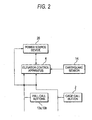
- Fig. 2 is a block diagram for explaining the elevator control apparatus 4 according to Embodiment 1 of this invention.
- the elevator control apparatus 4 is supplied with the signal from the cage call button 2 assembled in the cage manipulation panel 3, the signals from the hall call buttons 13a and 13b disposed at each floor, the signal from the earthquake sensor 14, etc. as stated before, and it is configured so as to perform the ascent/descent and stop of the cage 1, the travel control thereof to a refuge floor, etc. on the basis of the signals.
- the elevator control apparatus 4 in order to attain energy saving as in an ordinary elevator system, the elevator control apparatus 4 is configured so that, upon detecting a slack time zone, it may reduce standby electric power by instructing a power source device 20 to cut off a power source, thereby to cut off the power source device 20, or by selecting an energy saving mode.
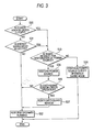
- Fig. 3 is a flow chart for explaining the operation of the elevator control apparatus 4.
- the elevator control apparatus 4 judges whether or not the power source device 20 is under cutoff (step S30). Besides, in a case where the power source device 20 is not under cutoff, the elevator control apparatus 4 judges whether or not the energy saving mode is selected in a slack state (step S31), and in a case where the energy saving mode is not selected, the elevator control apparatus 4 performs ordinary running (step S32).
- the elevator control apparatus 4 judges whether or not a request for the restoration of the power source is existent, from the hall call button 13a or 13b or the cage call button 2 disposed in the cage 1 (step S33), and in a case where the request for the restoration of the power source is existent, the elevator control apparatus 4 restores the power source (step S34). Besides, in a case where the request for the restoration of the power source is not existent, the elevator control apparatus 4 continues the power source cutoff or continues the energy saving mode (step S35).
- the elevator control apparatus 4 judges whether or not the earthquake sensor 14 is under operation (step S36), and in a case where the earthquake sensor 14 is not under operation, the elevator control apparatus 4 performs the ordinary running at the step S32. Besides, in a case where the earthquake sensor 15 is under operation, the elevator control apparatus 4 resets the earthquake sensor 15 (step S37) and thereafter performs the ordinary running at the step S32.
- Embodiment 1 in a case where an earthquake occurred during the cutoff of the power source or the selection of the energy saving mode of the elevator system and where the earthquake sensor 14 has operated, the earthquake sensor 14 is altered from a set state into a reset state in compliance with the request for the restoration of the power source of the elevator system, whereby the elevator system immediately falls into an available state, and the enhancement of service can be attained.
- Embodiment 1 there has been described the practicable example in which, in a case where an earthquake occurred during the cutoff of the power source or the selection of the energy saving mode of an elevator system and where an earthquake sensor 14 has operated, the earthquake sensor 14 is altered from a set state into a reset state in compliance with a request for the restoration of the power source, whereby the elevator system is immediately brought into an available state.
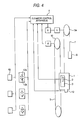
- Embodiment 2 a practicable example in the case where a fire occurred during the cutoff of the power source or the selection of the energy saving mode of an elevator system will be described in conjunction with the block diagram of Fig. 4 showing the general configuration of the elevator system, the block diagram of Fig. 5 for explaining an elevator control apparatus, and the flow chart of Fig. 6 for explaining the operation of the elevator system.
- a fire control switch 40 which operates by recognizing the occurrence of the fire is mounted in the desired place of each floor.
- a signal outputted from the fire control switch 40 is inputted to the elevator control apparatus 4, and the elevator control apparatus 4 is configured so as to perform the running control of the elevator system on the basis of the inputted signal.
- the remaining configuration is similar to that described in Embodiment 1 of Fig. 1 , and it shall be omitted from description.
- the elevator control apparatus 4 is supplied with a signal from a cage call button 2 assembled in a cage manipulation panel 3, signals from hall call buttons 13a and 13b disposed at each floor, the signal from the fire control switch 40, etc., and it is configured so as to perform the ascent/descent and stop control of a cage 1, etc. on the basis of the signals.
- the flow chart of Fig. 6 shows the operation of the elevator control apparatus 4 in the case where the fire occurred during the cutoff of the power source or the selection of the energy saving mode of the elevator system according to Embodiment 2.
- the elevator control apparatus 4 judges whether or not a power source device 20 is under cutoff (step S60). Besides, in a case where the power source device 20 is not under cutoff, the elevator control apparatus 4 judges whether or not the energy saving mode is selected in a slack state (step S61), and in a case where the energy saving mode is not selected, the elevator control apparatus 4 performs ordinary running (step S62).
- the elevator control apparatus 4 judges whether or not a request for the restoration of the power source is existent, from the hall call button 13a or 13b or the cage call button 2 disposed in the cage 1 (step S63), and in a case where the request for the restoration of the power source is existent, the elevator control apparatus 4 restores the power source (step S64). Besides, in a case where the request for the restoration of the power source is not existent, the elevator control apparatus 4 continues the power source cutoff or continues the selection of the energy saving mode (step S65).
- the elevator control apparatus 4 judges if the fire control switch 40 is under operation by recognizing the fire (step S66), and in a case where the fire control switch 40 is not under operation, the elevator control apparatus 4 performs the ordinary running at the step S62. Besides, in a case where the fire control switch 40 is under operation, the elevator control apparatus 4 stops the running of the elevator system (step S67).
- Embodiment 2 in a case where a fire occurred during the cutoff of the power source or the selection of the energy saving mode of the elevator system, a signal from the fire control switch 40 is confirmed in compliance with a request for the restoration of the power source of the elevator system, and subject to the selection of a fire control, the running of the elevator system is stopped without opening even the door of the cage, whereby a person and the cage can be respectively prevented from erroneously getting into the cage and from traveling to a refuge floor by fire control running, in spite of the lapse of a time period since the occurrence of the fire and the spread of the fire, so that the embodiment is preferable for keeping safety.
- Embodiment 2 there has been described the embodiment in which, in a case where a fire occurred during the cutoff of the power source or the selection of the energy saving mode of an elevator system, the running of the elevator system is stopped even in the existence of a request for the restoration of the power source of the elevator system.
- Embodiment 3 consists in further improving Embodiment 2 and reporting it to a user that the elevator system is in a running stop state, and the embodiment 3 will be described below.
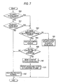
- Fig. 7 is a flow chart for explaining the operation of an elevator control apparatus according to Embodiment 3, and the general configuration of the elevator system is the same as in Figs. 4 and 5 , so that Embodiment 3 will be described in conjunction with these figures.
- steps S60 through S67 are the same as in Embodiment 2 in Fig. 6 , and hence, they are assigned the same step Nos. and shall be omitted from description.
- the running stop state of the elevator system is reported by, for example, turning ON and OFF the lamps of hall call buttons 13a and 13b disposed at each floor (step S70).
- the unavailability of the elevator system can be reported to a person intending to use the elevator system, who has manipulated the hall call button 13a or 13b, and the person intending to use the elevator system can recognize the state of the elevator system.
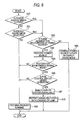
- Embodiment 4 consists in that the respective operations of the elevator control apparatuses in Embodiments 1 through 3 are performed only in compliance with the request for the restoration of the power source from the energy saving mode. More specifically, each of Embodiments 1 through 3 includes both the operations complying with the request for the restoration of the power source from the energy saving mode and with the request for the restoration of the power source during the cutoff of the power source, and it includes also a case where a request for the restoration of the power source from an ordinary stoppage of power supply is existent. In this embodiment 4, however, the elevator control apparatus is operated only in the restricted case where the request for the restoration of the power source from the energy saving mode is existent.
- Fig. 8 is a flow chart for explaining the operation of the elevator control apparatus according to Embodiment 4, and the general configuration of the elevator system is the same as in Figs. 4 and 5 , so that Embodiment 4 will be described in conjunction with these figures.
- steps S60 through S65, and steps S66, S67 and S70 are the same as explained in the flow chart of Fig. 7 in Embodiment 3, and hence, they are assigned the same step Nos. and shall be omitted from description.
- the elevator control apparatus 4 judges if the pertinent request is the request for the restoration of the power source from the energy saving mode (step S80). Only on the occasion of the request for the restoration from the energy saving mode, the elevator control apparatus 4 is caused to perform the respective operations described in Embodiments 1 through 3, so as to run the elevator system.
- Embodiment 4 The case where the request for the restoration of the power source from the energy saving mode is existent, and the case where the request for the restoration of the power source from the ordinary stoppage of power supply, are distinguished as in Embodiment 4, whereby on the occasion of start-up from the ordinary stoppage of power supply, the operations can be separated without performing such special running in which the state of the fire control switch is checked.
- Embodiment 4 has been described as the further improvement on Embodiment 3, the idea is, of course, applicable to the occasion of the occurrence of the earthquake in Embodiment 1.
- an elevator system and a running control method therefor consist in that, in addition to the attainment of reduction in the standby electric power of an elevator system, the elevator system is made available after the state of an earthquake sensor operating by sensing an earthquake or a fire control switch operating by recognizing the occurrence of a fire has been confirmed at the restoration of the power source of the elevator system under the cutoff of the power source or under the selection of an energy saving mode.
- the elevator system and the running control method therefor become excellent from the viewpoint of enhancing service or keeping safety, and the industrial applicability thereof is great.
Landscapes
- Engineering & Computer Science (AREA)
- Automation & Control Theory (AREA)
- Computer Networks & Wireless Communication (AREA)
- Life Sciences & Earth Sciences (AREA)
- Environmental & Geological Engineering (AREA)
- General Life Sciences & Earth Sciences (AREA)
- Geology (AREA)
- Remote Sensing (AREA)
- Maintenance And Inspection Apparatuses For Elevators (AREA)
- Elevator Control (AREA)
Claims (6)
- Aufzugssystem mit einer Aufzugssteuerungsvorrichtung (4), in die ein Betriebssignal von einem Erdbebensensor (14) eingegeben ist, der durch Erfassen eines Erdbebens tätig wird, wobei, falls ein Befehl zum Betreiben des Aufzugssystems besteht, während eine Energiequelle des Aufzugssystems abgesperrt ist, oder während ein Energiesparmodus ausgewählt ist, die Energiequelle des Aufzugssystems durch die Aufzugssteuerungsvorrichtung (4) in Abhängigkeit von dem Befehl wiederhergestellt wird; und
wobei die Aufzugssteuerungsvorrichtung (4) den Erdbebensensor (14) resettet und den Betrieb des Aufzugssystems steuert, wenn sie den Befehl zum Betreiben des Aufzugssystems in einem Zustand erhalten hat, in dem der Erdbebensensor (14) während des Absperrens der Energiequelle des Aufzugssystems oder während der Auswahl des Energiesparmodus tätig wurde. - Aufzugssystem mit einer Aufzugssteuerungsvorrichtung (4), in die ein Betriebssignal von einem Feuerkontrollschalter (40) eingegeben ist, der durch Erfassen des Auftretens eines Feuers tätig wird, wobei, falls ein Befehl zum Betreiben des Aufzugssystems besteht, während eine Energiequelle des Aufzugssystems abgesperrt ist, oder während ein Energiesparmodus ausgewählt ist, die Energiequelle des Aufzugssystems durch die Aufzugssteuerungsvorrichtung (4) in Abhängigkeit von dem Befehl wiederhergestellt wird; und
wobei die Aufzugssteuerungsvorrichtung (4) den Betrieb des Aufzugssystems anhält, wenn sie den Befehl zum Betreiben des Aufzugsystems in einem Zustand erhalten hat, in dem der Feuerkontrollschalter (40) während des Absperrens der Energiequelle des Aufzugssystems oder während der Auswahl des Energiesparmodus tätig wurde. - Aufzugssystem nach Anspruch 2, ferner mit Einrichtungen zum Anzeigen des Anhaltens des Betriebs des Aufzugssystems an einen Benutzer, wenn die Aufzugssteuerungsvorrichtung (4) den Befehl zum Betreiben des Aufzugssystems in dem Zustand erhalten hat, in dem der Feuerkontrollschalter tätig wurde.
- Betriebssteuerungsverfahren für ein Aufzugssystem mit einer Aufzugssteuerungsvorrichtung (4), in die ein Betriebssignal von einem Erdbebensensor (14) eingegeben ist, der der durch Erfassen eines Erdbebens tätig wird, wobei,
falls ein Befehl zum Betreiben des Aufzugssystems besteht, während eine Energiequelle des Aufzugssystems abgesperrt ist, oder während ein Energiesparmodus ausgewählt ist, die Energiequelle des Aufzugssystems durch die Aufzugssteuerungsvorrichtung (4) in Abhängigkeit von dem Befehl wiederhergestellt wird;
wobei das Betriebssteuerungsverfahren für ein Aufzugssystem umfasst:einen ersten Schritt des Beurteilens, ob das Aufzugssystem der Absperrung der Energiequelle oder der Auswahl des Energiesparmodus unterliegt;einen zweiten Schritt des Beurteilens des Bestehens odernicht-Bestehens des Befehls das Aufzugssystem zu betreiben,falls das Aufzugssystem gemäß dem ersten Schritt der Absperrung der Energiequelle oder der Auswahl des Energiesparmodus unterliegt;einen dritten Schritt des Beurteilens des Bestehens odernicht-Bestehens der Betätigung des Erdbebensensors (14), falls gemäß dem zweiten Schritt der Befehl zum Betreiben des Aufzugssystems besteht; undeinen vierten Schritt des Resettens des Erdbebensensors, falls gemäß dem dritten Schritt der Erdbebensensor tätig wurde. - Betriebssteuerungsverfahren für ein Aufzugssystem mit einer Aufzugssteuerungsvorrichtung (4), in die ein Betriebssignal von einem Feuerkontrollschalter (40) eingegeben ist, der durch Erfassen des Auftretens eines Feuers tätig wird, wobei, falls ein Befehl zum Betreiben des Aufzugssystems besteht, während eine Energiequelle des Aufzugssystems abgesperrt ist, oder während ein Energiesparmodus ausgewählt ist, die Energiequelle des Aufzugssystems durch die Aufzugssteuerungsvorrichtung (4) in Abhängigkeit von dem Befehl wiederhergestellt wird;
wobei das Betriebssteuerungsverfahren für ein Aufzugssystem umfasst:einen ersten Schritt des Beurteilens, ob das Aufzugssystem der Absperrung der Energiequelle oder der Auswahl des Energiesparmodus unterliegt;einen zweiten Schritt des Beurteilens des Bestehens odernicht-Bestehens des Befehls das Aufzugssystem zu betreiben,falls das Aufzugssystem gemäß dem ersten Schritt der Absperrung der Energiequelle oder der Auswahl des Energiesparmodus unterliegt;einen dritten Schritt des Beurteilens des Bestehens odernicht-Bestehens der Betätigung des Feuerkontrollschalters (40),falls gemäß dem zweiten Schritt der Befehl zum Betreiben des Aufzugssystems besteht; undeinen vierten Schritt des Anhaltens des Betriebs des Aufzugssystems, falls gemäß dem dritten Schritt der Feuerkontrollschalter tätig wurde. - Betriebssteuerungsverfahren für ein Aufzugssystem nach Anspruch 5, dadurch gekennzeichnet, dass es einen Schritt des Anzeigens des Anhaltens des Betriebs des Aufzugssystems an einen Benutzer aufweist, falls der Feuerkontrollschalter tätig wurde.
Applications Claiming Priority (2)
| Application Number | Priority Date | Filing Date | Title |
|---|---|---|---|
| JP2005111074A JP5059296B2 (ja) | 2005-04-07 | 2005-04-07 | エレベータ装置及びその運転制御方法 |
| PCT/JP2006/306154 WO2006114968A1 (ja) | 2005-04-07 | 2006-03-27 | エレベータ装置及びその運転制御方法 |
Publications (3)
| Publication Number | Publication Date |
|---|---|
| EP1867594A1 EP1867594A1 (de) | 2007-12-19 |
| EP1867594A4 EP1867594A4 (de) | 2013-08-14 |
| EP1867594B1 true EP1867594B1 (de) | 2014-06-11 |
Family
ID=37214599
Family Applications (1)
| Application Number | Title | Priority Date | Filing Date |
|---|---|---|---|
| EP06730102.8A Ceased EP1867594B1 (de) | 2005-04-07 | 2006-03-27 | Aufzugssystem und betriebssteuerungsverfahren dafür |
Country Status (5)
| Country | Link |
|---|---|
| EP (1) | EP1867594B1 (de) |
| JP (1) | JP5059296B2 (de) |
| KR (1) | KR100908347B1 (de) |
| CN (1) | CN101039862B (de) |
| WO (1) | WO2006114968A1 (de) |
Families Citing this family (11)
| Publication number | Priority date | Publication date | Assignee | Title |
|---|---|---|---|---|
| JPWO2011052015A1 (ja) * | 2009-10-30 | 2013-03-14 | 三菱電機株式会社 | エレベータの制御装置及び制御方法 |
| JP5558845B2 (ja) * | 2010-01-12 | 2014-07-23 | 東芝エレベータ株式会社 | エレベータの省電力制御システム |
| JP2012046319A (ja) * | 2010-08-26 | 2012-03-08 | Toshiba Elevator Co Ltd | エレベータ装置 |
| CN103261067B (zh) * | 2010-12-28 | 2014-12-17 | 奥的斯电梯公司 | 电梯控制系统 |
| JP5743320B2 (ja) * | 2011-03-03 | 2015-07-01 | 東芝エレベータ株式会社 | エレベータシステム |
| BR112013028661A2 (pt) * | 2011-06-21 | 2017-01-17 | Otis Elevator Co | sistema de elevador |
| CN102295205A (zh) * | 2011-08-19 | 2011-12-28 | 宁波市鸿腾机电有限公司 | 节能电梯系统及控制方法 |
| KR101443875B1 (ko) * | 2012-11-28 | 2014-09-24 | 유성전력 주식회사 | 에너지 저장 장치를 이용한 엘리베이터 전원 공급 시스템 |
| JP6149651B2 (ja) * | 2013-09-26 | 2017-06-21 | 住友電気工業株式会社 | 機器管理装置、統合機器管理装置、機器管理システム、機器管理方法および機器管理プログラム |
| JP6620666B2 (ja) * | 2016-05-06 | 2019-12-18 | フジテック株式会社 | エレベーターシステム及びその電源制御方法 |
| JP6598938B1 (ja) * | 2018-07-09 | 2019-10-30 | 東芝エレベータ株式会社 | エレベータの保守作業支援システム |
Family Cites Families (3)
| Publication number | Priority date | Publication date | Assignee | Title |
|---|---|---|---|---|
| JP2001002335A (ja) * | 1999-06-25 | 2001-01-09 | Hitachi Ltd | エレベーター装置 |
| JP2003146552A (ja) * | 2001-11-14 | 2003-05-21 | Mitsubishi Electric Corp | エレベータの運転装置 |
| JP2003341955A (ja) * | 2002-05-29 | 2003-12-03 | Mitsubishi Electric Corp | エレベータの火災時救出運転装置 |
-
2005
- 2005-04-07 JP JP2005111074A patent/JP5059296B2/ja not_active Expired - Fee Related
-
2006
- 2006-03-27 KR KR1020077007100A patent/KR100908347B1/ko not_active Expired - Fee Related
- 2006-03-27 WO PCT/JP2006/306154 patent/WO2006114968A1/ja not_active Ceased
- 2006-03-27 CN CN2006800009917A patent/CN101039862B/zh not_active Expired - Lifetime
- 2006-03-27 EP EP06730102.8A patent/EP1867594B1/de not_active Ceased
Also Published As
| Publication number | Publication date |
|---|---|
| EP1867594A1 (de) | 2007-12-19 |
| KR20070065345A (ko) | 2007-06-22 |
| JP5059296B2 (ja) | 2012-10-24 |
| CN101039862B (zh) | 2010-08-25 |
| KR100908347B1 (ko) | 2009-07-20 |
| WO2006114968A1 (ja) | 2006-11-02 |
| CN101039862A (zh) | 2007-09-19 |
| JP2006290501A (ja) | 2006-10-26 |
| EP1867594A4 (de) | 2013-08-14 |
Similar Documents
| Publication | Publication Date | Title |
|---|---|---|
| JP4071008B2 (ja) | エレベータ装置および昇降路監視装置の後付け方法 | |
| EP2421784B1 (de) | Sicherheitsanordnung für einen aufzug | |
| JP5599529B1 (ja) | 遠隔監視支援装置 | |
| KR101223303B1 (ko) | 엘리베이터 장치 | |
| EP1867594B1 (de) | Aufzugssystem und betriebssteuerungsverfahren dafür | |
| CN112135787B (zh) | 安全切换系统以及用于在正常运行模式与检查运行模式之间切换电梯设备的方法 | |
| EP1975110A1 (de) | Aufzugssteuersystem | |
| EP2497738B1 (de) | Benachrichtigungsvorrichtung für einen aufzug | |
| CN102381604A (zh) | 电梯装置 | |
| US20190389695A1 (en) | Elevator system | |
| EP2357149A1 (de) | Aufzugssteuervorrichtung | |
| JP2004359405A (ja) | エレベータの地震時遠隔救出方法 | |
| JP2008184301A (ja) | エレベータ制御システム | |
| JP6193822B2 (ja) | 制御基板 | |
| JP7586285B2 (ja) | エレベーター装置 | |
| JP4255687B2 (ja) | エレベータの運転制御装置 | |
| EP4549362B1 (de) | Sicherheitssystem für aufzug, verfahren zum betreiben eines sicherheitssystems und ein computerprogrammprodukt zur steuerung eines sicherheitsystems | |
| JP2012030916A (ja) | エレベータの地震救出運転装置 | |
| EP4549356A1 (de) | Sicherheitssystem für aufzug | |
| Jun et al. | Development of elevator intelligent safety control system based on PLC | |
| JP6537539B2 (ja) | エレベーターの制御装置および制御方法 | |
| WO2021090623A1 (ja) | エレベーター制御装置、エレベーター制御方法及びエレベーターシステム | |
| JP5226208B2 (ja) | 非常用エレベータの伝送制御システム | |
| JP2006225090A (ja) | エレベータシステム | |
| JPH08231147A (ja) | エレベータの着床誤差監視装置 |
Legal Events
| Date | Code | Title | Description |
|---|---|---|---|
| PUAI | Public reference made under article 153(3) epc to a published international application that has entered the european phase |
Free format text: ORIGINAL CODE: 0009012 |
|
| 17P | Request for examination filed |
Effective date: 20070411 |
|
| AK | Designated contracting states |
Kind code of ref document: A1 Designated state(s): DE |
|
| DAX | Request for extension of the european patent (deleted) | ||
| RBV | Designated contracting states (corrected) |
Designated state(s): DE |
|
| A4 | Supplementary search report drawn up and despatched |
Effective date: 20130715 |
|
| RIC1 | Information provided on ipc code assigned before grant |
Ipc: B66B 1/34 20060101AFI20130709BHEP Ipc: B66B 5/02 20060101ALI20130709BHEP Ipc: B66B 1/06 20060101ALI20130709BHEP |
|
| GRAP | Despatch of communication of intention to grant a patent |
Free format text: ORIGINAL CODE: EPIDOSNIGR1 |
|
| INTG | Intention to grant announced |
Effective date: 20140103 |
|
| GRAS | Grant fee paid |
Free format text: ORIGINAL CODE: EPIDOSNIGR3 |
|
| GRAA | (expected) grant |
Free format text: ORIGINAL CODE: 0009210 |
|
| AK | Designated contracting states |
Kind code of ref document: B1 Designated state(s): DE |
|
| REG | Reference to a national code |
Ref country code: DE Ref legal event code: R096 Ref document number: 602006041865 Country of ref document: DE Effective date: 20140724 |
|
| REG | Reference to a national code |
Ref country code: DE Ref legal event code: R097 Ref document number: 602006041865 Country of ref document: DE |
|
| PLBE | No opposition filed within time limit |
Free format text: ORIGINAL CODE: 0009261 |
|
| STAA | Information on the status of an ep patent application or granted ep patent |
Free format text: STATUS: NO OPPOSITION FILED WITHIN TIME LIMIT |
|
| 26N | No opposition filed |
Effective date: 20150312 |
|
| REG | Reference to a national code |
Ref country code: DE Ref legal event code: R097 Ref document number: 602006041865 Country of ref document: DE Effective date: 20150312 |
|
| REG | Reference to a national code |
Ref country code: DE Ref legal event code: R084 Ref document number: 602006041865 Country of ref document: DE |
|
| PGFP | Annual fee paid to national office [announced via postgrant information from national office to epo] |
Ref country code: DE Payment date: 20210316 Year of fee payment: 16 |
|
| REG | Reference to a national code |
Ref country code: DE Ref legal event code: R119 Ref document number: 602006041865 Country of ref document: DE |
|
| PG25 | Lapsed in a contracting state [announced via postgrant information from national office to epo] |
Ref country code: DE Free format text: LAPSE BECAUSE OF NON-PAYMENT OF DUE FEES Effective date: 20221001 |