EP1863950B1 - Multi-tray film precursor evaporation system and thin film deposition system incorporating same - Google Patents
Multi-tray film precursor evaporation system and thin film deposition system incorporating same Download PDFInfo
- Publication number
- EP1863950B1 EP1863950B1 EP05852347A EP05852347A EP1863950B1 EP 1863950 B1 EP1863950 B1 EP 1863950B1 EP 05852347 A EP05852347 A EP 05852347A EP 05852347 A EP05852347 A EP 05852347A EP 1863950 B1 EP1863950 B1 EP 1863950B1
- Authority
- EP
- European Patent Office
- Prior art keywords
- film precursor
- tray
- evaporation system
- wall
- container
- Prior art date
- Legal status (The legal status is an assumption and is not a legal conclusion. Google has not performed a legal analysis and makes no representation as to the accuracy of the status listed.)
- Not-in-force
Links
Images


Classifications
-
- C—CHEMISTRY; METALLURGY
- C23—COATING METALLIC MATERIAL; COATING MATERIAL WITH METALLIC MATERIAL; CHEMICAL SURFACE TREATMENT; DIFFUSION TREATMENT OF METALLIC MATERIAL; COATING BY VACUUM EVAPORATION, BY SPUTTERING, BY ION IMPLANTATION OR BY CHEMICAL VAPOUR DEPOSITION, IN GENERAL; INHIBITING CORROSION OF METALLIC MATERIAL OR INCRUSTATION IN GENERAL
- C23C—COATING METALLIC MATERIAL; COATING MATERIAL WITH METALLIC MATERIAL; SURFACE TREATMENT OF METALLIC MATERIAL BY DIFFUSION INTO THE SURFACE, BY CHEMICAL CONVERSION OR SUBSTITUTION; COATING BY VACUUM EVAPORATION, BY SPUTTERING, BY ION IMPLANTATION OR BY CHEMICAL VAPOUR DEPOSITION, IN GENERAL
- C23C16/00—Chemical coating by decomposition of gaseous compounds, without leaving reaction products of surface material in the coating, i.e. chemical vapour deposition [CVD] processes
- C23C16/44—Chemical coating by decomposition of gaseous compounds, without leaving reaction products of surface material in the coating, i.e. chemical vapour deposition [CVD] processes characterised by the method of coating
- C23C16/448—Chemical coating by decomposition of gaseous compounds, without leaving reaction products of surface material in the coating, i.e. chemical vapour deposition [CVD] processes characterised by the method of coating characterised by the method used for generating reactive gas streams, e.g. by evaporation or sublimation of precursor materials
- C23C16/4481—Chemical coating by decomposition of gaseous compounds, without leaving reaction products of surface material in the coating, i.e. chemical vapour deposition [CVD] processes characterised by the method of coating characterised by the method used for generating reactive gas streams, e.g. by evaporation or sublimation of precursor materials by evaporation using carrier gas in contact with the source material
-
- H—ELECTRICITY
- H01—ELECTRIC ELEMENTS
- H01L—SEMICONDUCTOR DEVICES NOT COVERED BY CLASS H10
- H01L21/00—Processes or apparatus adapted for the manufacture or treatment of semiconductor or solid state devices or of parts thereof
- H01L21/67—Apparatus specially adapted for handling semiconductor or electric solid state devices during manufacture or treatment thereof; Apparatus specially adapted for handling wafers during manufacture or treatment of semiconductor or electric solid state devices or components ; Apparatus not specifically provided for elsewhere
- H01L21/67005—Apparatus not specifically provided for elsewhere
- H01L21/67011—Apparatus for manufacture or treatment
- H01L21/67092—Apparatus for mechanical treatment
-
- C—CHEMISTRY; METALLURGY
- C23—COATING METALLIC MATERIAL; COATING MATERIAL WITH METALLIC MATERIAL; CHEMICAL SURFACE TREATMENT; DIFFUSION TREATMENT OF METALLIC MATERIAL; COATING BY VACUUM EVAPORATION, BY SPUTTERING, BY ION IMPLANTATION OR BY CHEMICAL VAPOUR DEPOSITION, IN GENERAL; INHIBITING CORROSION OF METALLIC MATERIAL OR INCRUSTATION IN GENERAL
- C23C—COATING METALLIC MATERIAL; COATING MATERIAL WITH METALLIC MATERIAL; SURFACE TREATMENT OF METALLIC MATERIAL BY DIFFUSION INTO THE SURFACE, BY CHEMICAL CONVERSION OR SUBSTITUTION; COATING BY VACUUM EVAPORATION, BY SPUTTERING, BY ION IMPLANTATION OR BY CHEMICAL VAPOUR DEPOSITION, IN GENERAL
- C23C16/00—Chemical coating by decomposition of gaseous compounds, without leaving reaction products of surface material in the coating, i.e. chemical vapour deposition [CVD] processes
- C23C16/06—Chemical coating by decomposition of gaseous compounds, without leaving reaction products of surface material in the coating, i.e. chemical vapour deposition [CVD] processes characterised by the deposition of metallic material
- C23C16/16—Chemical coating by decomposition of gaseous compounds, without leaving reaction products of surface material in the coating, i.e. chemical vapour deposition [CVD] processes characterised by the deposition of metallic material from metal carbonyl compounds
-
- H—ELECTRICITY
- H01—ELECTRIC ELEMENTS
- H01L—SEMICONDUCTOR DEVICES NOT COVERED BY CLASS H10
- H01L21/00—Processes or apparatus adapted for the manufacture or treatment of semiconductor or solid state devices or of parts thereof
- H01L21/67—Apparatus specially adapted for handling semiconductor or electric solid state devices during manufacture or treatment thereof; Apparatus specially adapted for handling wafers during manufacture or treatment of semiconductor or electric solid state devices or components ; Apparatus not specifically provided for elsewhere
- H01L21/67005—Apparatus not specifically provided for elsewhere
- H01L21/67011—Apparatus for manufacture or treatment
- H01L21/67155—Apparatus for manufacturing or treating in a plurality of work-stations
- H01L21/67207—Apparatus for manufacturing or treating in a plurality of work-stations comprising a chamber adapted to a particular process
- H01L21/6723—Apparatus for manufacturing or treating in a plurality of work-stations comprising a chamber adapted to a particular process comprising at least one plating chamber
-
- H—ELECTRICITY
- H01—ELECTRIC ELEMENTS
- H01L—SEMICONDUCTOR DEVICES NOT COVERED BY CLASS H10
- H01L21/00—Processes or apparatus adapted for the manufacture or treatment of semiconductor or solid state devices or of parts thereof
- H01L21/67—Apparatus specially adapted for handling semiconductor or electric solid state devices during manufacture or treatment thereof; Apparatus specially adapted for handling wafers during manufacture or treatment of semiconductor or electric solid state devices or components ; Apparatus not specifically provided for elsewhere
- H01L21/673—Apparatus specially adapted for handling semiconductor or electric solid state devices during manufacture or treatment thereof; Apparatus specially adapted for handling wafers during manufacture or treatment of semiconductor or electric solid state devices or components ; Apparatus not specifically provided for elsewhere using specially adapted carriers or holders; Fixing the workpieces on such carriers or holders
- H01L21/6735—Closed carriers
- H01L21/67389—Closed carriers characterised by atmosphere control
Definitions
- the present invention relates to a system for thin film deposition, and more particularly to a system for evaporating a film precursor and delivering the vapor to a deposition chamber.
- Cu copper
- Barriers/liners that are deposited onto dielectric materials can include refractive materials, such as tungsten (W), molybdenum (Mo), and tantalum (Ta), that are non-reactive and immiscible in Cu, and can offer low electrical resistivity.
- Current integration schemes that integrate Cu metallization and dielectric materials can require barrier/liner deposition processes at substrate temperatures between about 400°C and about 500°C, or lower.
- Cu integration schemes for technology nodes less than or equal to 130 nm currently utilize a low dielectric constant (low-k) inter-level dielectric, followed by a physical vapor deposition (PVD) TaN layer and Ta barrier layer, followed by a PVD Cu seed layer, and an electro-chemical deposition (ECD) Cu fill.
- PVD physical vapor deposition
- ECD electro-chemical deposition
- Ta layers are chosen for their adhesion properties (i.e., their ability to adhere on low-k films)
- Ta/TaN layers are generally chosen for their barrier properties (i.e., their ability to prevent Cu diffusion into the low-k film).
- Ru layers can be formed by thermally decomposing a ruthenium-containing precursor, such as a ruthenium carbonyl precursor, in a thermal chemical vapor deposition (TCVD) process.
- a ruthenium-containing precursor such as a ruthenium carbonyl precursor
- TCVD thermal chemical vapor deposition
- Material properties of Ru layers that are deposited by thermal decomposition of metal-carbonyl precursors can deteriorate when the substrate temperature is lowered to below about 400°C.
- an increase in the (electrical) resistivity of the Ru layers and poor surface morphology (e.g., the formation of nodules) at low deposition temperatures has been attributed to increased incorporation of CO reaction by-products into the thermally deposited Ru layers. Both effects can be explained by a reduced CO desorption rate from the thermal decomposition of the ruthenium-carbonyl precursor at substrate temperatures below about 400°C.
- metal-carbonyls such as ruthenium carbonyl
- ruthenium carbonyl can lead to poor deposition rates due to their low vapor pressure, and the transport issues associated therewith.
- the inventor has observed that current deposition systems suffer from such a low rate, making the deposition of such metal films impractical.
- US 2004/016404 , US 6270839 , WO 2004/011695 and US 4190965 disclose assemblies suitable for delivering precursor and comprise replaceable stackable trays.
- the present invention provides a multi-tray film precursor evaporation system, and a system for depositing a thin film from a film precursor vapor delivered from the multi-tray film precursor evaporation system.
- the film precursor may be a solid metal precursor.
- the present invention further provides a system for depositing a metal film from a solid metal precursor at a high rate.
- a film precursor evaporation system configured to be coupled to a thin film deposition system is provided that comprises a container having an outer wall and a bottom, and configured to be heated to an elevated temperature by a heater.
- a lid is configured to be sealably coupled to the container, and the lid comprises an outlet configured to be sealably coupled to the thin film deposition system.
- a tray stack is positioned in the container and includes a base tray and one or more upper trays.
- the base tray rests on the bottom of the container and has a base outer wall configured to retain the film precursor on the base tray, and a base support edge.
- the upper trays include a first upper tray supported on the base support edge and optional additional trays positioned on the first upper tray or on a preceding additional tray.
- the upper trays each have an outer wall and a shorter inner wall to retain the film precursor therebetween.
- An annular space is formed between the base and upper outer walls of the base tray and the upper trays and the outer wall of the container.
- Openings in the base and upper outer walls are coupled to the annular space to enable carrier gas to flow from the annular space, over the film precursor towards a central flow channel defined by the inner walls of the upper trays, and to exhaust through the outlet in the lid with film precursor vapor.
- the upper trays are separatable and stackable upon the base tray, and in another embodiment, the base and upper trays are formed as an integral, unitary piece.
- the present invention further provides a deposition system for forming a thin film on a substrate.
- the deposition system comprises a process chamber having a substrate holder configured to support the substrate and heat the substrate, a vapor distribution system configured to introduce a film precursor vapor above the substrate, and a pumping system configured to evacuate the process chamber.
- a film precursor evaporation system of the present invention configured to evaporate a film precursor is coupled to the vapor distribution system by a vapor delivery system having a first end coupled to the outlet of the film precursor evaporation system and a second end coupled to an inlet of the vapor distribution system of the process chamber.
- a carrier gas supply system is coupled to the annular space in the container for providing carrier gas to the tray stack, which is then exhausted through the outlet with film precursor vapor and delivered to the process chamber via the vapor delivery system.
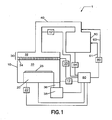
- FIG. 1 depicts a schematic view of a deposition system according to an embodiment of the invention
- FIG. 2 depicts a schematic view of a deposition system according to another embodiment of the invention.
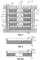
- FIG. 3 presents in cross-sectional view a film precursor evaporation system according to an embodiment of the invention
- FIG. 4 presents in cross-sectional view a bottom tray for use in a film precursor evaporation system according to an embodiment of the invention
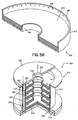
- FIG. 5A presents in cross-sectional view a stackable upper tray for use in a film precursor evaporation system according to an embodiment of the invention
- FIG. 5B presents in perspective view the tray of FIG. 5A ;
- FIG. 6 presents in perspective view a film precursor evaporation system according to another embodiment of the invention.
- FIG. 7 illustrates a method of operating a film precursor evaporation system of the invention.
- FIG. 1 illustrates a deposition system 1 for depositing a thin film, such as a ruthenium (Ru) or a rhenium (Re) metal film, on a substrate according to one embodiment.
- the deposition system 1 comprises a process chamber 10 having a substrate holder 20 configured to support a substrate 25, upon which the thin film is formed.
- the process chamber 10 is coupled to a film precursor evaporation system 50 via a vapor precursor delivery system 40.
- the process chamber 10 is further coupled to a vacuum pumping system 38 through a duct 36, wherein the pumping system 38 is configured to evacuate the process chamber 10, vapor precursor delivery system 40, and film precursor evaporation system 50 to a pressure suitable for forming the thin film on substrate 25, and suitable for evaporation of a film precursor (not shown) in the film precursor evaporation system 50.
- the film precursor evaporation system 50 is configured to store a film precursor and heat the film precursor to a temperature sufficient for evaporating the film precursor, while introducing vapor phase film precursor to the vapor precursor delivery system 40.
- the film precursor can, for example, comprise a solid film precursor.
- the film precursor can include a solid metal precursor.
- the film precursor can include a metal-carbonyl.
- the metal-carbonyl can include ruthenium carbonyl (Ru 3 (CO) 12 ), or rhenium carbonyl (Re 2 (CO) 10 ).
- the metal-carbonyl can include W(CO) 6 , Mo(CO) 6 , Co 2 (CO) 8 , Rh 4 (CO) 12 , Cr(CO) 6 , or OS 3 (CO) 12 .
- the film precursor evaporation system 50 is coupled to an evaporation temperature control system 54 configured to control the evaporation temperature.
- the temperature of the film precursor is generally elevated to approximately 40 to 45°C in conventional systems in order to sublime, for example, ruthenium carbonyl.
- the vapor pressure of the ruthenium carbonyl ranges from approximately 1 to approximately 3 mTorr.
- a carrier gas is passed over the film precursor or by the film precursor.
- the carrier gas can include, for example, an inert gas, such as a noble gas (i.e., He, Ne, Ar, Kr, Xe), or a monoxide, such as carbon monoxide (CO), for use with metal-carbonyls, or a mixture thereof.
- a carrier gas supply system 60 is coupled to the film precursor evaporation system 50, and it is configured to, for instance, supply the carrier gas above the film precursor via feed line 61.
- carrier gas supply system 60 is coupled to the vapor precursor delivery system 40 and is configured to supply the carrier gas to the vapor of the film precursor via feed line 63 as or after it enters the vapor precursor delivery system 40.
- the carrier gas supply system 60 can comprise a gas source, one or more control valves, one or more filters, and a mass flow controller.
- the flow rate of carrier gas can range from approximately 5 sccm (standard cubic centimeters per minute) to approximately 1000 sccm.
- the flow rate of carrier gas can range from about 10 sccm to about 200 sccm.
- the flow rate of carrier gas can range from about 20 sccm to about 100 sccm.
- the film precursor vapor Downstream from the film precursor evaporation system 50, the film precursor vapor flows with the carrier gas through the vapor precursor delivery system 40 until it enters a vapor distribution system 30 coupled to the process chamber 10.
- the vapor precursor delivery system 40 can be coupled to a vapor line temperature control system 42 in order to control the vapor line temperature, and prevent decomposition of the film precursor vapor as well as condensation of the film precursor vapor.
- the vapor line temperature can be set to a value approximately equal to or greater than the evaporation temperature.
- the vapor precursor delivery system 40 can be characterized by a high conductance in excess of about 50 liters/second.
- the vapor distribution system 30, coupled to the process chamber 10, comprises a plenum 32 within which the vapor disperses prior to passing through a vapor distribution plate 34 and entering a processing zone 33 above substrate 25.
- the vapor distribution plate 34 can be coupled to a distribution plate temperature control system 35 configured to control the temperature of the vapor distribution plate 34.
- the temperature of the vapor distribution plate can be set to a value approximately equal to the vapor line temperature. However, it may be less, or it may be greater.
- the substrate holder 20 is configured to elevate the temperature of substrate 25, by virtue of the substrate holder 20 being coupled to a substrate temperature control system 22.
- the substrate temperature control system 22 can be configured to elevate the temperature of substrate 25 up to approximately 500°C.
- the substrate temperature can range from about 100°C to about 500°C.
- the substrate temperature can range from about 300°C to about 400°C.
- process chamber 10 can be coupled to a chamber temperature control system 12 configured to control the temperature of the chamber walls.
- conventional systems have contemplated operating the film precursor evaporation system 50, as well as the vapor precursor delivery system 40, within a temperature range of approximately 40 to 45°C for ruthenium carbonyl in order to limit metal vapor precursor decomposition, and metal vapor precursor condensation.
- ruthenium carbonyl precursor can decompose at elevated temperatures to form by-products, such as those illustrated below: R ⁇ u 3 ⁇ CO 12 * ad ⁇ R ⁇ u 3 ⁇ CO x * ad + 12 - x ⁇ CO g or, R ⁇ u 3 ⁇ CO x * ad ⁇ 3 ⁇ Ru s + xCO g wherein these by-products can adsorb, i.e., condense, on the interior surfaces of the deposition system 1. The accumulation of material on these surfaces can cause problems from one substrate to the next, such as process repeatability.
- ruthenium carbonyl precursor can condense at depressed temperatures to cause recrystallization, viz. R ⁇ u 3 ⁇ CO 12 g ⁇ R ⁇ u 3 ⁇ CO 12 * ad
- the deposition rate becomes extremely low, due in part to the low vapor pressure of ruthenium carbonyl.
- the deposition rate can be as low as approximately 1 Angstrom per minute. Therefore, according to one embodiment, the evaporation temperature is elevated to be greater than or equal to approximately 40°C. Alternatively, the evaporation temperature is elevated to be greater than or equal to approximately 50°C. In an exemplary embodiment of the present invention, the evaporation temperature is elevated to be greater than or equal to approximately 60°C. In a further exemplary embodiment, the evaporation temperature is elevated to range from approximately 60 to 100°C, and for example from approximately 60 to 90°C.
- the elevated temperature increases the evaporation rate due to the higher vapor pressure (e.g., nearly an order of magnitude larger) and, hence, it is expected by the inventors to increase the deposition rate. It may also be desirable to periodically clean deposition system 1 following processing of one or more substrates. For example, additional details on a cleaning method and system can be obtained from co-pending US Patent Application No. 10/998,394 , filed on even date herewith and entitled "Method and System for Performing In-situ Cleaning of a Deposition System", which is herein incorporated by reference in its entirety.
- the deposition rate is proportional to the amount of film precursor that is evaporated and transported to the substrate prior to decomposition, or condensation, or both. Therefore, in order to achieve a desired deposition rate, and to maintain consistent processing performance (i.e., deposition rate, film thickness, film uniformity, film morphology, etc.) from one substrate to the next, it is important to provide the ability to monitor, adjust, or control the flow rate of the film precursor vapor.
- an operator may indirectly determine the flow rate of film precursor vapor by using the evaporation temperature, and a pre-determined relationship between the evaporation temperature and the flow rate. However, processes and their performance drift in time, and hence it is imperative that the flow rate is measured more accurately.
- the deposition system 1 can further include a control system 80 configured to operate, and control the operation of the deposition system 1.
- the control system 80 is coupled to the process chamber 10, the substrate holder 20, the substrate temperature control system 22, the chamber temperature control system 12, the vapor distribution system 30, the vapor precursor delivery system 40, the film precursor evaporation system 50, and the carrier gas supply system 60.
- FIG. 2 illustrates a deposition system 100 for depositing a thin film, such as a ruthenium (Ru) or a rhenium (Re) metal film, on a substrate.
- the deposition system 100 comprises a process chamber having a substrate holder 120 configured to support a substrate 125, upon which the thin film is formed.
- the process chamber 110 is coupled to a precursor delivery system 105 having film precursor evaporation system 150 configured to store and evaporate a film precursor (not shown), and a vapor precursor delivery system 140 configured to transport film precursor vapor.
- the process chamber 110 comprises an upper chamber section 111, a lower chamber section 112, and an exhaust chamber 113.
- An opening 114 is formed within lower chamber section 112, where bottom section 112 couples with exhaust chamber 113.
- substrate holder 120 provides a horizontal surface to support substrate (or wafer) 125, which is to be processed.
- the substrate holder 120 can be supported by a cylindrical support member 122, which extends upward from the lower portion of exhaust chamber 113.
- An optional guide ring 124 for positioning the substrate 125 on the substrate holder 120 is provided on the edge of substrate holder 120.
- the substrate holder 120 comprises a heater 126 coupled to substrate holder temperature control system 128.
- the heater 126 can, for example, include one or more resistive heating elements. Alternately, the heater 126 can, for example, include a radiant heating system, such as a tungsten-halogen lamp.
- the substrate holder temperature control system 128 can include a power source for providing power to the one or more heating elements, one or more temperature sensors for measuring the substrate temperature, or the substrate holder temperature, or both, and a controller configured to perform at least one of monitoring, adjusting, or controlling the temperature of the substrate or substrate holder.
- the heated substrate 125 can thermally decompose the vapor of film precursor vapor, such as a metal-carbonyl precursor, and enable deposition of a thin film, such as a metal layer, on the substrate 125.
- the film precursor includes a solid precursor.
- the film precursor includes a metal precursor.
- the film precursor includes a solid metal precursor.
- the film precursor includes a metal-carbonyl precursor.
- the film precursor can be a ruthenium-carbonyl precursor, for example Ru 3 (CO) 12 .
- the film precursor can be a rhenium carbonyl precursor, for example Re 2 (CO) 10 .
- the film precursor can be W(CO) 6 , Mo(CO) 6 , Co 2 (CO) 8 , Rh 4 (CO) 12 , Cr(CO) 6 , or Os 3 (CO) 12 .
- the substrate holder 120 is heated to a pre-determined temperature that is suitable for depositing, for instance, a desired Ru, Re, or other metal layer onto the substrate 125.
- a heater (not shown), coupled to a chamber temperature control system 121, can be embedded in the walls of process chamber 110 to heat the chamber walls to a pre-determined temperature. The heater can maintain the temperature of the walls of process chamber 110 from about 40°C to about 100°C, for example from about 40°C to about 80°C.
- a pressure gauge (not shown) is used to measure the process chamber pressure.
- Vapor distribution system 130 is coupled to the upper chamber section 111 of process chamber 110.
- Vapor distribution system 130 comprises a vapor distribution plate 131 configured to introduce precursor vapor from vapor distribution plenum 132 to a processing zone 133 above substrate 125 through one or more orifices 134.
- an opening 135 is provided in the upper chamber section 111 for introducing a vapor precursor from vapor precursor delivery system 140 into vapor distribution plenum 132.
- temperature control elements 136 such as concentric fluid channels configured to flow a cooled or heated fluid, are provided for controlling the temperature of the vapor distribution system 130, and thereby prevent the decomposition of the film precursor inside the vapor distribution system 130.
- a fluid such as water, can be supplied to the fluid channels from a vapor distribution temperature control system 138.
- the vapor distribution temperature control system 138 can include a fluid source, a heat exchanger, one or more temperature sensors for measuring the fluid temperature or vapor distribution plate temperature or both, and a controller configured to control the temperature of the vapor distribution plate 131 from about 20°C to about 100°C.
- Film precursor evaporation system 150 is configured to hold a film precursor, and evaporate (or sublime) the film precursor by elevating the temperature of the film precursor.
- a precursor heater 154 is provided for heating the film precursor to maintain the film precursor at a temperature that produces a desired vapor pressure of film precursor.
- the precursor heater 154 is coupled to an evaporation temperature control system 156 configured to control the temperature of the film precursor.
- the precursor heater 154 can be configured to adjust the temperature of the film precursor (or evaporation temperature) to be greater than or equal to approximately 40°C.
- the evaporation temperature is elevated to be greater than or equal to approximately 50°C.
- the evaporation temperature is elevated to be greater than or equal to approximately 60°C.
- the evaporation temperature is elevated to range from approximately 60 to 100°C, and in another embodiment, to range from approximately 60 to 90°C.
- a carrier gas can be passed over the film precursor, or by the film precursor.
- the carrier gas can include, for example, an inert gas, such as a noble gas (i.e., He, Ne, Ar, Kr, Xe), or a monoxide, such as carbon monoxide (CO), for use with metal-carbonyls, or a mixture thereof.
- a carrier gas supply system 160 is coupled to the film precursor evaporation system 150, and it is configured to, for instance, supply the carrier gas above the film precursor.
- carrier gas supply system 160 can also be coupled to the vapor precursor delivery system 140 to supply the carrier gas to the vapor of the film precursor as or after it enters the vapor precursor delivery system 140.
- the carrier gas supply system 160 can comprise a gas source 161, one or more control valves 162, one or more filters 164, and a mass flow controller 165.
- the flow rate of carrier gas can range from approximately 5 sccm (standard cubic centimeters per minute) to approximately 1000 sccm. In one embodiment, for instance, the flow rate of carrier gas can range from about 10 sccm to about 200 sccm. In another embodiment, for instance, the flow rate of carrier gas can range from about 20 sccm to about 100 sccm.
- a sensor 166 is provided for measuring the total gas flow from the film precursor evaporation system 150.
- the sensor 166 can, for example, comprise a mass flow controller, and the amount of film precursor delivered to the process chamber 110, can be determined using sensor 166 and mass flow controller 165.
- the sensor 166 can comprise a light absorption sensor to measure the concentration of the film precursor in the gas flow to the process chamber 110.
- a bypass line 167 can be located downstream from sensor 166, and it can connect the vapor delivery system 140 to an exhaust line 116.
- Bypass line 167 is provided for evacuating the vapor precursor delivery system 140, and for stabilizing the supply of the film precursor to the process chamber 110.
- a bypass valve 168 located downstream from the branching of the vapor precursor delivery system 140, is provided on bypass line 167.
- the vapor precursor delivery system 140 comprises a high conductance vapor line having first and second valves 141 and 142 respectively. Additionally, the vapor precursor delivery system 140 can further comprise a vapor line temperature control system 143 configured to heat the vapor precursor delivery system 140 via heaters (not shown). The temperatures of the vapor lines can be controlled to avoid condensation of the film precursor in the vapor line. The temperature of the vapor lines can be controlled from about 20°C to about 100°C, or from about 40°C to about 90°C. For example, the vapor line temperature can be set to a value approximately equal to or greater than the evaporation temperature.
- dilution gases can be supplied from a dilution gas supply system 190.
- the dilution gas can include, for example, an inert gas, such as a noble gas (i.e., He, Ne, Ar, Kr, Xe), or a monoxide, such as carbon monoxide (CO), for use with metal-carbonyls, or a mixture thereof.
- the dilution gas supply system 190 is coupled to the vapor precursor delivery system 140, and it is configured to, for instance, supply the dilution gas to vapor film precursor.
- the dilution gas supply system 190 can comprise a gas source 191, one or more control valves 192, one or more filters 194, and a mass flow controller 195.
- the flow rate of carrier gas can range from approximately 5 sccm (standard cubic centimeters per minute) to approximately 1000 sccm.
- Mass flow controllers 165 and 195, and valves 162, 192, 168, 141, and 142 are controlled by controller 196, which controls the supply, shutoff, and the flow of the carrier gas, the film precursor vapor, and the dilution gas.
- Sensor 166 is also connected to controller 196 and, based on output of the sensor 166, controller 196 can control the carrier gas flow through mass flow controller 165 to obtain the desired film precursor flow to the process chamber 110.
- the exhaust line 116 connects exhaust chamber 113 to pumping system 118.
- a vacuum pump 119 is used to evacuate process chamber 110 to the desired degree of vacuum, and to remove gaseous species from the process chamber 110 during processing.
- An automatic pressure controller (APC) 115 and a trap 117 can be used in series with the vacuum pump 119.
- the vacuum pump 119 can include a turbo-molecular pump (TMP) capable of a pumping seed up to 5000 liters per second (and greater). Alternately, the vacuum pump 119 can include a dry roughing pump.
- TMP turbo-molecular pump
- the vacuum pump 119 can include a dry roughing pump.
- the carrier gas, dilution gas, or film precursor vapor, or any combination thereof can be introduced into the process chamber 110, and the chamber pressure can be adjusted by the APC 115.
- the chamber pressure can range from approximately 1 mTorr to approximately 500 mTorr, and in a further example, the chamber pressure can range from about 5 mTorr to 50 mTorr.
- the APC 115 can comprise a butterfly-type valve, or a gate valve.
- the trap 117 can collect unreacted precursor material, and by-products from the process chamber 110.
- three substrate lift pins 127 are provided for holding, raising, and lowering the substrate 125.
- the substrate lift pins 127 are coupled to plate 123, and can be lowered to below the upper surface of substrate holder 120.
- a drive mechanism 129 utilizing, for example, an air cylinder, provides means for raising and lowering the plate 123.
- Substrate 125 can be transferred into and out of process chamber 110 through gate valve 200, and chamber feed-through passage 202 via a robotic transfer system (not shown), and received by the substrate lift pins 127. Once the substrate 125 is received from the transfer system, it can be lowered to the upper surface of the substrate holder 120 by lowering the substrate lift pins 127.
- a controller 180 includes a microprocessor, a memory, and a digital I/O port capable of generating control voltages sufficient to communicate and activate inputs of the processing system 100 as well as monitor outputs from the processing system 100. Moreover, the processing system controller 180 is coupled to and exchanges information with process chamber 110; precursor delivery system 105, which includes controller 196, vapor line temperature control system 142, and evaporation temperature control system 156; vapor distribution temperature control system 138; vacuum pumping system 118; and substrate holder temperature control system 128. In the vacuum pumping system 118, the controller 180 is coupled to and exchanges information with the automatic pressure controller 115 for controlling the pressure in the process chamber 110.
- a program stored in the memory is utilized to control the aforementioned components of deposition system 100 according to a stored process recipe.
- processing system controller 180 is a DELL PRECISION WORKSTATION 610TM, available from Dell Corporation, Dallas, Texas.
- the controller 180 may also be implemented as a general-purpose computer, digital signal process, etc.
- Controller 180 may be locally located relative to the deposition system 100, or it may be remotely located relative to the deposition system 100 via an internet or intranet. Thus, controller 180 can exchange data with the deposition system 100 using at least one of a direct connection, an intranet, or the internet. Controller 180 may be coupled to an intranet at a customer site (i.e., a device maker, etc.), or coupled to an intranet at a vendor site (i.e., an equipment manufacturer). Furthermore, another computer (i.e., controller, server, etc.) can access controller 180 to exchange data via at least one of a direct connection, an intranet, or the internet.
- a customer site i.e., a device maker, etc.
- a vendor site i.e., an equipment manufacturer
- another computer i.e., controller, server, etc.
- controller 180 can access controller 180 to exchange data via at least one of a direct connection, an intranet, or the internet.
- the film precursor evaporation system 300 comprises a container 310 having an outer wall 312 and a bottom 314. Additionally, the film precursor evaporation system 300 comprises a lid 320 configured to be sealably coupled to the container 310, wherein the lid 320 includes an outlet 322 configured to be sealably coupled to a thin film deposition system, such as the one depicted in FIGS. 1 or 2 .
- the container 310 and lid 320 form a sealed environment when coupled to the thin film deposition system.
- the container 310 and lid 320 can, for example, be fabricated from A6061 aluminum, and may or may not include a coating applied thereon.
- the container 310 is configured to be coupled to a heater (not shown) in order to elevate the evaporation temperature of the film precursor evaporation system 300, and to a temperature control system (not shown) in order to perform at least one of monitoring, adjusting, or controlling the evaporation temperature.
- a heater not shown
- a temperature control system not shown
- film precursor evaporates (or sublimes) forming film precursor vapor to be transported through the vapor delivery system to the thin film deposition system.
- the container 310 is also sealably coupled to a carrier gas supply system (not shown), wherein container 310 is configured to receive a carrier gas for transporting the film precursor vapor.
- the film precursor evaporation system 300 further comprises a base tray 330 configured to rest on the bottom 314 of the container 310, and having abase outer wall 332 configured to retain the film precursor 350 on the base tray 330.
- the base outer wall 332 includes a base support edge 333 for supporting upper trays thereon, as discussed below.
- the base outer wall 332 includes one or more base tray openings 334 configured to flow the carrier gas from the carrier gas supply system (not shown), over the film precursor 350 towards a center of the container 310, and along a central flow channel 318 to exhaust through the outlet 322 in the lid 320 with film precursor vapor. Consequently, the film precursor level in the base tray 330 should be below the position of the base tray openings 334.
- the film precursor evaporation system 300 further comprises one or more stackable upper trays 340 configured to support the film precursor 350, and configured to be positioned or stacked upon at least one of the base tray 330 or another of the stackable upper trays 340.
- Each of the stackable upper trays 340 comprises an upper outer wall 342 and an inner wall 344 configured to retain the film precursor 350 therebetween.
- the inner walls 344 define the central flow channel 318.
- the upper outer wall 342 further includes an upper support edge 343 for supporting an additional upper tray 340.
- a first upper tray 340 is positioned to be supported on base support edge 333 of base tray 330, and if desired, one or more additional upper trays may be positioned to be supported on the upper support edge 343 of a preceding upper tray 340.
- the upper outer wall 342 of each upper tray 340 includes one or more upper tray openings 346 configured to flow the carrier gas from the carrier gas supply system (not shown), over the film precursor 350 towards central flow channel 318 of the container 310, and exhaust through the outlet 322 in the lid 320 with film precursor vapor. Consequently, inner walls 344 should be shorter than upper outer walls 342 to allow the carrier gas to flow substantially radially to the central flow channel 318. Additionally, the film precursor level in each upper tray 340 should be at or below the height of the inner walls 342, and below the position of the upper tray openings 346.
- the base tray 330 and the stackable upper trays 340 are depicted to be cylindrical in shape. However, the shape can vary. For instance, the shape of the trays can be rectangular, square or oval. Similarly, the inner walls 344, and thus central upper flow channel 318, can be differently shaped.
- a stack 370 is formed, which provides for an annular space 360 between the base outer wall 332 of the base tray 330 and the container outer wall 312, and between the upper outer walls 342 of the one or more stackable upper trays 340 and the container outer wall 312.
- the container 310 can further comprise one or more spacers (not shown) configured to space the base outer wall 332 of the base tray 330 and the upper outer walls 342 of the one or more stackable upper trays 340 from the container outer wall 312, and thereby ensure equal spacing within the annular space 360.
- the container 310 is configured such that the base outer wall 332 and the upper outer walls 342 are in vertical alignment.
- the number of trays can range from two (2) to twenty (20) and, for example in one embodiment, the number of trays can be five (5), as shown in FIG. 3 .
- the stack 370 includes a base tray 330 and at least one upper tray 340 supported by the base tray 330.
- the base tray 330 may be as shown in FIGS. 3 and 4 , or may have the same configuration as the upper trays 340 as they are shown in FIGS. 3-5B . In other words, the base tray 330 may have an inner wall.
- a system 300' may include a container 310' with a stack 370' that comprises a single unitary piece having a base tray 330 integral with one or more upper trays 340, as shown in FIG. 6 , such that the base outer wall 332 and upper outer walls 342 are integral.
- Integral is understood to include a monolithic structure, such as an integrally molded structure having no discernible boundaries between trays, as well as a permanently adhesively or mechanically joined structure where there is permanent joinder between the trays.
- Separatable is understood to include no joinder between trays or temporary joinder, whether adhesive or mechanical.
- the base tray 330 and each of the upper trays 340, whether stackable or integral, are configured to support a film precursor 350.
- the film precursor 350 includes a solid precursor.
- the film precursor 350 includes a liquid precursor.
- the film precursor 350 includes a metal precursor.
- the film precursor 350 includes a solid metal precursor.
- the film precursor 350 includes a metal-carbonyl precursor.
- the film precursor 350 can be a ruthenium-carbonyl precursor, for example Ru 3 (CO) 12 .
- the film precursor 350 can be a rhenium carbonyl precursor, for example Re 2 (CO) 10 .
- the film precursor 350 can be W(CO) 6 , Mo(CO) 6 , Co 2 (CO) 8 , Rh 4 (CO) 12 , Cr(CO) 6 , or Os 3 (CO) 12 .
- the film precursor 350 can include a solid precursor.
- the solid precursor can take the form of a solid powder, or it may take the form of one or more solid tablets.
- the one or more solid tablets can be prepared by a number of processes, including a sintering process, a stamping process, a dipping process, or a spin-on process, or any combination thereof.
- the solid precursor in solid tablet form may or may not adhere to the base tray 330 or upper tray 340.
- a refractory metal powder may be sintered in a sintering furnace configured for both vacuum and inert gas atmospheres, and temperature up to 2000°C and 2500°C.
- a refractory metal powder can be dispersed in a fluid medium, dispensed on a tray, and distributed evenly over the tray surfaces using a spin coating process. The refractory metal spin coat may then be thermally cured.
- carrier gas is supplied to the container 310 from a carrier gas supply system (not shown).
- the carrier gas may be coupled to the container 310 through the lid 320 via a gas supply line (not shown) sealably coupled to the lid 320.
- the gas supply line feeds a gas channel 380 that extends downward through the outer wall 312 of container 310, passes through the bottom 314 of container 310 and opens to the annular space 360.
- the inner diameter of the container outer wall 312 can, for example, range from approximately 10 cm to approximately 100 cm and, for example, can range from approximately 15 cm to approximately 40 cm.
- the inner diameter of outer wall 312 can be 20 cm.
- the diameter of the outlet 322 and the inner diameter of the inner walls 344 of the upper trays 340 can, for example, range from approximately 1 cm to 30 cm and, additionally, for example, the outlet diameter and inner wall diameter can range from approximately 5 to approximately 20 cm.
- the outlet diameter can be 10 cm.
- the outer diameter of the base tray 330 and each of the upper trays 340 can range from approximately 75% to approximately 99% of the inner diameter of the outer wall 312 of container 310 and, for example, the tray diameter can range from approximately 85% to 99% of the inner diameter of the outer wall 312 of container 310.
- the tray diameter can be 19.75 cm.
- the height of the base outer wall 332 of base tray 330 and of the upper outer wall 342 of each of the upper trays 340 can range from approximately 5 mm to approximately 50 mm and, for example, the height of each is approximately 30 mm.
- the height of each inner wall 344 can range from approximately 10% to approximately 90% of the height of the upper outer wall 342.
- the height of each inner wall can range from approximately 2 mm to approximately 45 mm and, for example, is approximately 20 mm.
- the one or more base tray openings 334 and the one or more upper tray openings 346 can include one or more slots.
- the one or more base tray openings 334 and the one or more upper tray openings 346 can include one or more orifices.
- the diameter of each orifice can, for example, range from approximately 0.4 mm to approximately 2 mm.
- the diameter of each orifice can be approximately 1 mm.
- the orifice diameter and width of annular space 360 are chosen such that the conductance through annular space 360 is sufficiently larger than the net conductance of the orifices in order to maintain substantially uniform distribution of the carrier gas throughout the annular space 360.
- the number of orifices can, for example, range from approximately 2 to approximately 1000 orifices and, by way of further example, can range from approximately 50 to approximately 100 orifices.
- the one or more base tray openings 334 can include seventy two (72), orifices of 1 mm diameter
- the one or more stackable tray openings 346 can include seventy two (72) orifices of 1 mm diameter, wherein the width of the annular space 360 is approximately 2.65 mm.
- the film precursor evaporation system 300 or 300' may be used as either film precursor evaporation system 50 in FIG. 1 , or film precursor evaporation system 150 in FIG. 2 .
- system 300 or 300' may be used in any film deposition system suitable for depositing a thin film on a substrate from precursor vapor.
- a flow chart 700 is used to illustrate the steps in depositing the thin film in a deposition system of the present invention.
- the thin film deposition begins in 710 with placing a substrate in the deposition system in succession for forming the thin film on the substrate.
- the deposition system can include any one of the depositions systems described above in FIGS. 1 and 2 .
- the deposition system can include a process chamber for facilitating the deposition process, and a substrate holder coupled to the process chamber and configured to support the substrate.
- a film precursor is introduced to the deposition system.
- the film precursor is introduced to a film precursor evaporation system coupled to the process chamber via a precursor vapor delivery system. Additionally, for instance, the precursor vapor delivery system can be heated.
- the film precursor is heated to form a film precursor vapor.
- the film precursor vapor can then be transported to the process chamber through the precursor vapor delivery system.
- the substrate is heated to a substrate temperature sufficient to decompose the film precursor vapor, and, in 750, the substrate is exposed to the film precursor vapor. Steps 710 to 750 may be repeated successively a desired number of times to deposit a metal film on a desired number of substrates.
- the stack of trays 370 or 370', or one or more of the base or upper trays 330, 340, can be periodically replaced in 760 in order to replenish the level of film precursor 350 in each tray.
Landscapes
- Chemical & Material Sciences (AREA)
- Engineering & Computer Science (AREA)
- General Chemical & Material Sciences (AREA)
- Chemical Kinetics & Catalysis (AREA)
- Materials Engineering (AREA)
- Mechanical Engineering (AREA)
- Metallurgy (AREA)
- Organic Chemistry (AREA)
- Physics & Mathematics (AREA)
- Condensed Matter Physics & Semiconductors (AREA)
- General Physics & Mathematics (AREA)
- Manufacturing & Machinery (AREA)
- Computer Hardware Design (AREA)
- Microelectronics & Electronic Packaging (AREA)
- Power Engineering (AREA)
- Chemical Vapour Deposition (AREA)
- Electrodes Of Semiconductors (AREA)
Applications Claiming Priority (2)
| Application Number | Priority Date | Filing Date | Title |
|---|---|---|---|
| US10/998,420 US7638002B2 (en) | 2004-11-29 | 2004-11-29 | Multi-tray film precursor evaporation system and thin film deposition system incorporating same |
| PCT/US2005/043018 WO2006058310A1 (en) | 2004-11-29 | 2005-11-29 | Multi-tray film precursor evaporation system and thin film deposition system incorporating same |
Publications (2)
| Publication Number | Publication Date |
|---|---|
| EP1863950A1 EP1863950A1 (en) | 2007-12-12 |
| EP1863950B1 true EP1863950B1 (en) | 2011-05-18 |
Family
ID=36096429
Family Applications (1)
| Application Number | Title | Priority Date | Filing Date |
|---|---|---|---|
| EP05852347A Not-in-force EP1863950B1 (en) | 2004-11-29 | 2005-11-29 | Multi-tray film precursor evaporation system and thin film deposition system incorporating same |
Country Status (8)
| Country | Link |
|---|---|
| US (2) | US7638002B2 (zh) |
| EP (1) | EP1863950B1 (zh) |
| JP (1) | JP5015002B2 (zh) |
| KR (1) | KR101194888B1 (zh) |
| CN (2) | CN101065515B (zh) |
| AT (1) | ATE510043T1 (zh) |
| TW (1) | TWI300956B (zh) |
| WO (1) | WO2006058310A1 (zh) |
Cited By (1)
| Publication number | Priority date | Publication date | Assignee | Title |
|---|---|---|---|---|
| WO2018218373A1 (en) * | 2017-06-02 | 2018-12-06 | Simon Fraser University | Method of patterned deposition employing pressurized fluids and thermal gradients |
Families Citing this family (59)
| Publication number | Priority date | Publication date | Assignee | Title |
|---|---|---|---|---|
| US6921062B2 (en) * | 2002-07-23 | 2005-07-26 | Advanced Technology Materials, Inc. | Vaporizer delivery ampoule |
| US7270848B2 (en) * | 2004-11-23 | 2007-09-18 | Tokyo Electron Limited | Method for increasing deposition rates of metal layers from metal-carbonyl precursors |
| US7484315B2 (en) | 2004-11-29 | 2009-02-03 | Tokyo Electron Limited | Replaceable precursor tray for use in a multi-tray solid precursor delivery system |
| US7488512B2 (en) | 2004-11-29 | 2009-02-10 | Tokyo Electron Limited | Method for preparing solid precursor tray for use in solid precursor evaporation system |
| US7638002B2 (en) | 2004-11-29 | 2009-12-29 | Tokyo Electron Limited | Multi-tray film precursor evaporation system and thin film deposition system incorporating same |
| US20060185597A1 (en) * | 2004-11-29 | 2006-08-24 | Kenji Suzuki | Film precursor evaporation system and method of using |
| US7708835B2 (en) * | 2004-11-29 | 2010-05-04 | Tokyo Electron Limited | Film precursor tray for use in a film precursor evaporation system and method of using |
| DE102004062552A1 (de) * | 2004-12-24 | 2006-07-06 | Aixtron Ag | Vorrichtung zum Verdampfen von kondensierten Stoffen |
| US7345184B2 (en) * | 2005-03-31 | 2008-03-18 | Tokyo Electron Limited | Method and system for refurbishing a metal carbonyl precursor |
| US7651570B2 (en) | 2005-03-31 | 2010-01-26 | Tokyo Electron Limited | Solid precursor vaporization system for use in chemical vapor deposition |
| US8268078B2 (en) * | 2006-03-16 | 2012-09-18 | Tokyo Electron Limited | Method and apparatus for reducing particle contamination in a deposition system |
| JP4847365B2 (ja) * | 2006-03-22 | 2011-12-28 | キヤノン株式会社 | 蒸着源および蒸着装置 |
| US7892358B2 (en) * | 2006-03-29 | 2011-02-22 | Tokyo Electron Limited | System for introducing a precursor gas to a vapor deposition system |
| US20070231489A1 (en) * | 2006-03-29 | 2007-10-04 | Tokyo Electron Limited | Method for introducing a precursor gas to a vapor deposition system |
| US20080241805A1 (en) | 2006-08-31 | 2008-10-02 | Q-Track Corporation | System and method for simulated dosimetry using a real time locating system |
| US7473634B2 (en) * | 2006-09-28 | 2009-01-06 | Tokyo Electron Limited | Method for integrated substrate processing in copper metallization |
| WO2008045972A2 (en) * | 2006-10-10 | 2008-04-17 | Asm America, Inc. | Precursor delivery system |
| US7846256B2 (en) * | 2007-02-23 | 2010-12-07 | Tokyo Electron Limited | Ampule tray for and method of precursor surface area |
| DE112008000604T5 (de) * | 2007-03-06 | 2010-01-28 | Tokyo Electron Ltd. | Steuereinrichtung einer Bedampfungsvorrichtung und Steuerverfahren einer Bedampfungsvorrichtung |
| US20080242088A1 (en) * | 2007-03-29 | 2008-10-02 | Tokyo Electron Limited | Method of forming low resistivity copper film structures |
| US7829454B2 (en) * | 2007-09-11 | 2010-11-09 | Tokyo Electron Limited | Method for integrating selective ruthenium deposition into manufacturing of a semiconductior device |
| US7704879B2 (en) * | 2007-09-27 | 2010-04-27 | Tokyo Electron Limited | Method of forming low-resistivity recessed features in copper metallization |
| US7884012B2 (en) * | 2007-09-28 | 2011-02-08 | Tokyo Electron Limited | Void-free copper filling of recessed features for semiconductor devices |
| WO2009064427A2 (en) * | 2007-11-13 | 2009-05-22 | Mckinley James J | Variable concentration dynamic headspace vapor source generator |
| US9034105B2 (en) * | 2008-01-10 | 2015-05-19 | American Air Liquide, Inc. | Solid precursor sublimator |
| US7776740B2 (en) * | 2008-01-22 | 2010-08-17 | Tokyo Electron Limited | Method for integrating selective low-temperature ruthenium deposition into copper metallization of a semiconductor device |
| US8247030B2 (en) * | 2008-03-07 | 2012-08-21 | Tokyo Electron Limited | Void-free copper filling of recessed features using a smooth non-agglomerated copper seed layer |
| US7799681B2 (en) * | 2008-07-15 | 2010-09-21 | Tokyo Electron Limited | Method for forming a ruthenium metal cap layer |
| US20100081274A1 (en) * | 2008-09-29 | 2010-04-01 | Tokyo Electron Limited | Method for forming ruthenium metal cap layers |
| US7977235B2 (en) * | 2009-02-02 | 2011-07-12 | Tokyo Electron Limited | Method for manufacturing a semiconductor device with metal-containing cap layers |
| US8716132B2 (en) * | 2009-02-13 | 2014-05-06 | Tokyo Electron Limited | Radiation-assisted selective deposition of metal-containing cap layers |
| US8720082B2 (en) * | 2009-06-05 | 2014-05-13 | Desmet Ballestra North America, Inc. | Desolventizer toaster with vapor recycle |
| US8997775B2 (en) * | 2011-05-24 | 2015-04-07 | Rohm And Haas Electronic Materials Llc | Vapor delivery device, methods of manufacture and methods of use thereof |
| US8776821B2 (en) * | 2011-05-24 | 2014-07-15 | Rohm And Haas Electronic Materials Llc | Vapor delivery device, methods of manufacture and methods of use thereof |
| KR20210135341A (ko) | 2012-05-31 | 2021-11-12 | 엔테그리스, 아이엔씨. | 배취식 침착을 위한 고 물질 플럭스를 갖는 유체의 소스 시약-기반 수송 |
| US9841671B2 (en) | 2013-07-03 | 2017-12-12 | Murata Machinery, Ltd. | Storage container |
| US10392700B2 (en) * | 2014-04-21 | 2019-08-27 | Entegris, Inc. | Solid vaporizer |
| US9951420B2 (en) * | 2014-11-10 | 2018-04-24 | Sol Voltaics Ab | Nanowire growth system having nanoparticles aerosol generator |
| KR102360536B1 (ko) * | 2015-03-06 | 2022-02-08 | 엔테그리스, 아이엔씨. | 고체 공급원 전달을 위한 고-순도 텅스텐 헥사카보닐 |
| CN105624650B (zh) * | 2016-01-04 | 2018-11-23 | 京东方科技集团股份有限公司 | 一种装置及该装置的使用方法 |
| KR20170119360A (ko) * | 2016-04-18 | 2017-10-27 | 삼성전자주식회사 | 고체 소스 공급 유닛, 가스 공급 유닛, 그리고 기판 처리 방법 |
| JP6595421B2 (ja) | 2016-08-24 | 2019-10-23 | 東芝メモリ株式会社 | 気化システム |
| US10876205B2 (en) | 2016-09-30 | 2020-12-29 | Asm Ip Holding B.V. | Reactant vaporizer and related systems and methods |
| US11926894B2 (en) | 2016-09-30 | 2024-03-12 | Asm Ip Holding B.V. | Reactant vaporizer and related systems and methods |
| JP6895372B2 (ja) * | 2017-12-12 | 2021-06-30 | 東京エレクトロン株式会社 | 原料容器 |
| US20190186003A1 (en) * | 2017-12-14 | 2019-06-20 | Entegris, Inc. | Ampoule vaporizer and vessel |
| JP7376278B2 (ja) | 2018-08-16 | 2023-11-08 | エーエスエム・アイピー・ホールディング・ベー・フェー | 固体原料昇華器 |
| CN110885970B (zh) * | 2018-09-11 | 2024-06-21 | 北京北方华创微电子装备有限公司 | 固体前驱体蒸汽的稳压和纯化装置以及ald沉积设备 |
| WO2020092501A2 (en) * | 2018-10-31 | 2020-05-07 | Ecodyst, Inc. | Falling film evaporator system and methods |
| JP6887688B2 (ja) * | 2019-02-07 | 2021-06-16 | 株式会社高純度化学研究所 | 蒸発原料用容器、及びその蒸発原料用容器を用いた固体気化供給システム |
| JP6901153B2 (ja) | 2019-02-07 | 2021-07-14 | 株式会社高純度化学研究所 | 薄膜形成用金属ハロゲン化合物の固体気化供給システム。 |
| WO2020251696A1 (en) | 2019-06-10 | 2020-12-17 | Applied Materials, Inc. | Processing system for forming layers |
| US11624113B2 (en) | 2019-09-13 | 2023-04-11 | Asm Ip Holding B.V. | Heating zone separation for reactant evaporation system |
| US11661653B2 (en) | 2019-12-18 | 2023-05-30 | L'air Liquide, Societe Anonyme Pour L'etude Et L'exploitation Des Procedes Georges Claude | Vapor delivery systems for solid and liquid materials |
| CN113529053B (zh) * | 2021-09-13 | 2021-12-28 | 浙江陶特容器科技股份有限公司 | 一种用于半导体加工的固态前驱体源升华装置及方法 |
| CN114751052B (zh) * | 2022-04-30 | 2023-11-24 | 苏州宇信特殊包装股份有限公司 | 一种防潮脆盘及其加工装置 |
| CN114811423A (zh) * | 2022-05-18 | 2022-07-29 | 江苏南大光电材料股份有限公司 | 一种固态源气化装置 |
| CN115046127A (zh) * | 2022-06-24 | 2022-09-13 | 江苏南大光电材料股份有限公司 | 用于固体化合物供应的钢瓶结构 |
| CN116103636A (zh) * | 2023-04-12 | 2023-05-12 | 上海星原驰半导体有限公司 | 固相前驱体输出装置及气相沉积系统 |
Family Cites Families (55)
| Publication number | Priority date | Publication date | Assignee | Title |
|---|---|---|---|---|
| US3003249A (en) * | 1958-05-01 | 1961-10-10 | Templeton Robert Alexa Spencer | Treatment of products and materials |
| US3801294A (en) * | 1971-12-15 | 1974-04-02 | Corning Glass Works | Method of producing glass |
| US4190965A (en) * | 1979-01-15 | 1980-03-04 | Alternative Pioneering Systems, Inc. | Food dehydrator |
| US4378987A (en) * | 1981-10-15 | 1983-04-05 | Corning Glass Works | Low temperature method for making optical fibers |
| US4817557A (en) * | 1983-05-23 | 1989-04-04 | Anicon, Inc. | Process and apparatus for low pressure chemical vapor deposition of refractory metal |
| US4948623A (en) * | 1987-06-30 | 1990-08-14 | International Business Machines Corporation | Method of chemical vapor deposition of copper, silver, and gold using a cyclopentadienyl/metal complex |
| US4938999A (en) * | 1988-07-11 | 1990-07-03 | Jenkin William C | Process for coating a metal substrate by chemical vapor deposition using a metal carbonyl |
| DE69033760T2 (de) * | 1990-01-08 | 2001-10-25 | Lsi Logic Corp | Struktur zum Filtern von Prozessgasen zum Einsatz in einer Kammer für chemische Dampfabscheidung |
| US6113982A (en) * | 1990-06-25 | 2000-09-05 | Lanxide Technology Company, Lp | Composite bodies and methods for making same |
| JPH0598445A (ja) | 1991-07-05 | 1993-04-20 | Chodendo Hatsuden Kanren Kiki Zairyo Gijutsu Kenkyu Kumiai | 有機金属化学気相蒸着用原料容器 |
| US5221354A (en) * | 1991-11-04 | 1993-06-22 | General Electric Company | Apparatus and method for gas phase coating of hollow articles |
| JPH06306584A (ja) | 1993-04-21 | 1994-11-01 | Asahi Glass Co Ltd | 真空蒸着用原料成形体の製造方法 |
| US6024915A (en) * | 1993-08-12 | 2000-02-15 | Agency Of Industrial Science & Technology | Coated metal particles, a metal-base sinter and a process for producing same |
| JPH1025576A (ja) * | 1996-04-05 | 1998-01-27 | Dowa Mining Co Ltd | Cvd成膜法における原料化合物の昇華方法 |
| US6133159A (en) * | 1998-08-27 | 2000-10-17 | Micron Technology, Inc. | Methods for preparing ruthenium oxide films |
| US6203619B1 (en) * | 1998-10-26 | 2001-03-20 | Symetrix Corporation | Multiple station apparatus for liquid source fabrication of thin films |
| AU6954300A (en) * | 1999-07-12 | 2001-01-30 | Asml Us, Inc. | Method and system for in situ cleaning of semiconductor manufacturing equipment using combination chemistries |
| JP3909792B2 (ja) * | 1999-08-20 | 2007-04-25 | パイオニア株式会社 | 化学気相成長法における原料供給装置及び原料供給方法 |
| US6380080B2 (en) * | 2000-03-08 | 2002-04-30 | Micron Technology, Inc. | Methods for preparing ruthenium metal films |
| US6440494B1 (en) * | 2000-04-05 | 2002-08-27 | Tokyo Electron Limited | In-situ source synthesis for metal CVD |
| US6429127B1 (en) * | 2000-06-08 | 2002-08-06 | Micron Technology, Inc. | Methods for forming rough ruthenium-containing layers and structures/methods using same |
| US6903005B1 (en) * | 2000-08-30 | 2005-06-07 | Micron Technology, Inc. | Method for the formation of RuSixOy-containing barrier layers for high-k dielectrics |
| US20040161545A1 (en) * | 2000-11-28 | 2004-08-19 | Shipley Company, L.L.C. | Adhesion method |
| US20030019428A1 (en) * | 2001-04-28 | 2003-01-30 | Applied Materials, Inc. | Chemical vapor deposition chamber |
| US6718126B2 (en) * | 2001-09-14 | 2004-04-06 | Applied Materials, Inc. | Apparatus and method for vaporizing solid precursor for CVD or atomic layer deposition |
| US20030111014A1 (en) * | 2001-12-18 | 2003-06-19 | Donatucci Matthew B. | Vaporizer/delivery vessel for volatile/thermally sensitive solid and liquid compounds |
| US6812143B2 (en) * | 2002-04-26 | 2004-11-02 | International Business Machines Corporation | Process of forming copper structures |
| US20030211736A1 (en) * | 2002-05-07 | 2003-11-13 | Tokyo Electron Limited | Method for depositing tantalum silicide films by thermal chemical vapor deposition |
| US7300038B2 (en) * | 2002-07-23 | 2007-11-27 | Advanced Technology Materials, Inc. | Method and apparatus to help promote contact of gas with vaporized material |
| US6921062B2 (en) * | 2002-07-23 | 2005-07-26 | Advanced Technology Materials, Inc. | Vaporizer delivery ampoule |
| US6915592B2 (en) * | 2002-07-29 | 2005-07-12 | Applied Materials, Inc. | Method and apparatus for generating gas to a processing chamber |
| EP1525337A2 (en) | 2002-07-30 | 2005-04-27 | ASM America, Inc. | Sublimation system employing carrier gas |
| JP2004137480A (ja) * | 2002-09-20 | 2004-05-13 | Tdk Corp | 蛍光体薄膜およびその製造方法ならびにelパネル |
| JP4126219B2 (ja) * | 2002-11-06 | 2008-07-30 | 東京エレクトロン株式会社 | 成膜方法 |
| US7156380B2 (en) * | 2003-09-29 | 2007-01-02 | Asm International, N.V. | Safe liquid source containers |
| US20050147749A1 (en) * | 2004-01-05 | 2005-07-07 | Msp Corporation | High-performance vaporizer for liquid-precursor and multi-liquid-precursor vaporization in semiconductor thin film deposition |
| US7270848B2 (en) * | 2004-11-23 | 2007-09-18 | Tokyo Electron Limited | Method for increasing deposition rates of metal layers from metal-carbonyl precursors |
| US7279421B2 (en) * | 2004-11-23 | 2007-10-09 | Tokyo Electron Limited | Method and deposition system for increasing deposition rates of metal layers from metal-carbonyl precursors |
| US7488512B2 (en) * | 2004-11-29 | 2009-02-10 | Tokyo Electron Limited | Method for preparing solid precursor tray for use in solid precursor evaporation system |
| US7638002B2 (en) | 2004-11-29 | 2009-12-29 | Tokyo Electron Limited | Multi-tray film precursor evaporation system and thin film deposition system incorporating same |
| US8435351B2 (en) * | 2004-11-29 | 2013-05-07 | Tokyo Electron Limited | Method and system for measuring a flow rate in a solid precursor delivery system |
| US7484315B2 (en) * | 2004-11-29 | 2009-02-03 | Tokyo Electron Limited | Replaceable precursor tray for use in a multi-tray solid precursor delivery system |
| US20060115590A1 (en) * | 2004-11-29 | 2006-06-01 | Tokyo Electron Limited; International Business Machines Corporation | Method and system for performing in-situ cleaning of a deposition system |
| US20060185597A1 (en) * | 2004-11-29 | 2006-08-24 | Kenji Suzuki | Film precursor evaporation system and method of using |
| US20060182886A1 (en) * | 2005-02-15 | 2006-08-17 | Guidotti Emmanuel P | Method and system for improved delivery of a precursor vapor to a processing zone |
| US7273814B2 (en) * | 2005-03-16 | 2007-09-25 | Tokyo Electron Limited | Method for forming a ruthenium metal layer on a patterned substrate |
| US7651570B2 (en) * | 2005-03-31 | 2010-01-26 | Tokyo Electron Limited | Solid precursor vaporization system for use in chemical vapor deposition |
| US7566477B2 (en) * | 2005-03-31 | 2009-07-28 | Tokyo Electron Limited | Method for saturating a carrier gas with precursor vapor |
| US7396766B2 (en) * | 2005-03-31 | 2008-07-08 | Tokyo Electron Limited | Low-temperature chemical vapor deposition of low-resistivity ruthenium layers |
| US7132128B2 (en) * | 2005-03-31 | 2006-11-07 | Tokyo Electron Limited | Method and system for depositing material on a substrate using a solid precursor |
| US7482269B2 (en) * | 2005-09-28 | 2009-01-27 | Tokyo Electron Limited | Method for controlling the step coverage of a ruthenium layer on a patterned substrate |
| JP4960720B2 (ja) * | 2006-02-10 | 2012-06-27 | 東京エレクトロン株式会社 | 膜前駆体蒸発システムにおいて使用される膜前駆体のトレーおよびその使用方法 |
| US20070237895A1 (en) * | 2006-03-30 | 2007-10-11 | Tokyo Electron Limited | Method and system for initiating a deposition process utilizing a metal carbonyl precursor |
| US7473634B2 (en) * | 2006-09-28 | 2009-01-06 | Tokyo Electron Limited | Method for integrated substrate processing in copper metallization |
| US7763311B2 (en) * | 2007-03-28 | 2010-07-27 | Tokyo Electron Limited | Method for heating a substrate prior to a vapor deposition process |
-
2004
- 2004-11-29 US US10/998,420 patent/US7638002B2/en active Active
-
2005
- 2005-10-03 CN CN2005800409120A patent/CN101065515B/zh not_active Expired - Fee Related
- 2005-11-29 EP EP05852347A patent/EP1863950B1/en not_active Not-in-force
- 2005-11-29 CN CN200580040914XA patent/CN101065516B/zh active Active
- 2005-11-29 KR KR1020077008440A patent/KR101194888B1/ko active IP Right Grant
- 2005-11-29 JP JP2007543581A patent/JP5015002B2/ja active Active
- 2005-11-29 WO PCT/US2005/043018 patent/WO2006058310A1/en active Application Filing
- 2005-11-29 AT AT05852347T patent/ATE510043T1/de not_active IP Right Cessation
- 2005-11-29 TW TW094141834A patent/TWI300956B/zh active
-
2006
- 2006-09-29 US US11/537,575 patent/US7459396B2/en active Active
Cited By (1)
| Publication number | Priority date | Publication date | Assignee | Title |
|---|---|---|---|---|
| WO2018218373A1 (en) * | 2017-06-02 | 2018-12-06 | Simon Fraser University | Method of patterned deposition employing pressurized fluids and thermal gradients |
Also Published As
| Publication number | Publication date |
|---|---|
| TWI300956B (en) | 2008-09-11 |
| WO2006058310A1 (en) | 2006-06-01 |
| JP5015002B2 (ja) | 2012-08-29 |
| ATE510043T1 (de) | 2011-06-15 |
| US7638002B2 (en) | 2009-12-29 |
| CN101065515A (zh) | 2007-10-31 |
| EP1863950A1 (en) | 2007-12-12 |
| US20070032079A1 (en) | 2007-02-08 |
| KR101194888B1 (ko) | 2012-10-25 |
| JP2008522033A (ja) | 2008-06-26 |
| CN101065516B (zh) | 2010-12-01 |
| CN101065516A (zh) | 2007-10-31 |
| US7459396B2 (en) | 2008-12-02 |
| KR20070089785A (ko) | 2007-09-03 |
| US20060112882A1 (en) | 2006-06-01 |
| CN101065515B (zh) | 2010-05-26 |
| TW200629376A (en) | 2006-08-16 |
Similar Documents
| Publication | Publication Date | Title |
|---|---|---|
| EP1863950B1 (en) | Multi-tray film precursor evaporation system and thin film deposition system incorporating same | |
| US7484315B2 (en) | Replaceable precursor tray for use in a multi-tray solid precursor delivery system | |
| US7488512B2 (en) | Method for preparing solid precursor tray for use in solid precursor evaporation system | |
| US7651570B2 (en) | Solid precursor vaporization system for use in chemical vapor deposition | |
| US7132128B2 (en) | Method and system for depositing material on a substrate using a solid precursor | |
| US7846256B2 (en) | Ampule tray for and method of precursor surface area | |
| US7708835B2 (en) | Film precursor tray for use in a film precursor evaporation system and method of using | |
| US20060185597A1 (en) | Film precursor evaporation system and method of using | |
| US8435351B2 (en) | Method and system for measuring a flow rate in a solid precursor delivery system | |
| US8268078B2 (en) | Method and apparatus for reducing particle contamination in a deposition system | |
| JP4960720B2 (ja) | 膜前駆体蒸発システムにおいて使用される膜前駆体のトレーおよびその使用方法 | |
| US20070218200A1 (en) | Method and apparatus for reducing particle formation in a vapor distribution system | |
| US20060115590A1 (en) | Method and system for performing in-situ cleaning of a deposition system | |
| US7566477B2 (en) | Method for saturating a carrier gas with precursor vapor | |
| US7858522B2 (en) | Method for reducing carbon monoxide poisoning in a thin film deposition system |
Legal Events
| Date | Code | Title | Description |
|---|---|---|---|
| PUAI | Public reference made under article 153(3) epc to a published international application that has entered the european phase |
Free format text: ORIGINAL CODE: 0009012 |
|
| 17P | Request for examination filed |
Effective date: 20070427 |
|
| AK | Designated contracting states |
Kind code of ref document: A1 Designated state(s): AT BE BG CH CY CZ DE DK EE ES FI FR GB GR HU IE IS IT LI LT LU LV MC NL PL PT RO SE SI SK TR |
|
| DAX | Request for extension of the european patent (deleted) | ||
| GRAP | Despatch of communication of intention to grant a patent |
Free format text: ORIGINAL CODE: EPIDOSNIGR1 |
|
| GRAS | Grant fee paid |
Free format text: ORIGINAL CODE: EPIDOSNIGR3 |
|
| GRAA | (expected) grant |
Free format text: ORIGINAL CODE: 0009210 |
|
| AK | Designated contracting states |
Kind code of ref document: B1 Designated state(s): AT BE BG CH CY CZ DE DK EE ES FI FR GB GR HU IE IS IT LI LT LU LV MC NL PL PT RO SE SI SK TR |
|
| REG | Reference to a national code |
Ref country code: GB Ref legal event code: FG4D |
|
| REG | Reference to a national code |
Ref country code: CH Ref legal event code: EP |
|
| REG | Reference to a national code |
Ref country code: IE Ref legal event code: FG4D |
|
| REG | Reference to a national code |
Ref country code: DE Ref legal event code: R096 Ref document number: 602005028179 Country of ref document: DE Effective date: 20110630 |
|
| REG | Reference to a national code |
Ref country code: NL Ref legal event code: VDEP Effective date: 20110518 |
|
| PG25 | Lapsed in a contracting state [announced via postgrant information from national office to epo] |
Ref country code: SE Free format text: LAPSE BECAUSE OF FAILURE TO SUBMIT A TRANSLATION OF THE DESCRIPTION OR TO PAY THE FEE WITHIN THE PRESCRIBED TIME-LIMIT Effective date: 20110518 Ref country code: LT Free format text: LAPSE BECAUSE OF FAILURE TO SUBMIT A TRANSLATION OF THE DESCRIPTION OR TO PAY THE FEE WITHIN THE PRESCRIBED TIME-LIMIT Effective date: 20110518 Ref country code: PT Free format text: LAPSE BECAUSE OF FAILURE TO SUBMIT A TRANSLATION OF THE DESCRIPTION OR TO PAY THE FEE WITHIN THE PRESCRIBED TIME-LIMIT Effective date: 20110919 |
|
| PG25 | Lapsed in a contracting state [announced via postgrant information from national office to epo] |
Ref country code: BE Free format text: LAPSE BECAUSE OF FAILURE TO SUBMIT A TRANSLATION OF THE DESCRIPTION OR TO PAY THE FEE WITHIN THE PRESCRIBED TIME-LIMIT Effective date: 20110518 Ref country code: SI Free format text: LAPSE BECAUSE OF FAILURE TO SUBMIT A TRANSLATION OF THE DESCRIPTION OR TO PAY THE FEE WITHIN THE PRESCRIBED TIME-LIMIT Effective date: 20110518 Ref country code: IS Free format text: LAPSE BECAUSE OF FAILURE TO SUBMIT A TRANSLATION OF THE DESCRIPTION OR TO PAY THE FEE WITHIN THE PRESCRIBED TIME-LIMIT Effective date: 20110918 Ref country code: CY Free format text: LAPSE BECAUSE OF FAILURE TO SUBMIT A TRANSLATION OF THE DESCRIPTION OR TO PAY THE FEE WITHIN THE PRESCRIBED TIME-LIMIT Effective date: 20110518 Ref country code: LV Free format text: LAPSE BECAUSE OF FAILURE TO SUBMIT A TRANSLATION OF THE DESCRIPTION OR TO PAY THE FEE WITHIN THE PRESCRIBED TIME-LIMIT Effective date: 20110518 Ref country code: ES Free format text: LAPSE BECAUSE OF FAILURE TO SUBMIT A TRANSLATION OF THE DESCRIPTION OR TO PAY THE FEE WITHIN THE PRESCRIBED TIME-LIMIT Effective date: 20110829 Ref country code: AT Free format text: LAPSE BECAUSE OF FAILURE TO SUBMIT A TRANSLATION OF THE DESCRIPTION OR TO PAY THE FEE WITHIN THE PRESCRIBED TIME-LIMIT Effective date: 20110518 Ref country code: FI Free format text: LAPSE BECAUSE OF FAILURE TO SUBMIT A TRANSLATION OF THE DESCRIPTION OR TO PAY THE FEE WITHIN THE PRESCRIBED TIME-LIMIT Effective date: 20110518 Ref country code: GR Free format text: LAPSE BECAUSE OF FAILURE TO SUBMIT A TRANSLATION OF THE DESCRIPTION OR TO PAY THE FEE WITHIN THE PRESCRIBED TIME-LIMIT Effective date: 20110819 |
|
| PG25 | Lapsed in a contracting state [announced via postgrant information from national office to epo] |
Ref country code: NL Free format text: LAPSE BECAUSE OF FAILURE TO SUBMIT A TRANSLATION OF THE DESCRIPTION OR TO PAY THE FEE WITHIN THE PRESCRIBED TIME-LIMIT Effective date: 20110518 |
|
| PG25 | Lapsed in a contracting state [announced via postgrant information from national office to epo] |
Ref country code: EE Free format text: LAPSE BECAUSE OF FAILURE TO SUBMIT A TRANSLATION OF THE DESCRIPTION OR TO PAY THE FEE WITHIN THE PRESCRIBED TIME-LIMIT Effective date: 20110518 Ref country code: CZ Free format text: LAPSE BECAUSE OF FAILURE TO SUBMIT A TRANSLATION OF THE DESCRIPTION OR TO PAY THE FEE WITHIN THE PRESCRIBED TIME-LIMIT Effective date: 20110518 |
|
| PG25 | Lapsed in a contracting state [announced via postgrant information from national office to epo] |
Ref country code: PL Free format text: LAPSE BECAUSE OF FAILURE TO SUBMIT A TRANSLATION OF THE DESCRIPTION OR TO PAY THE FEE WITHIN THE PRESCRIBED TIME-LIMIT Effective date: 20110518 Ref country code: DK Free format text: LAPSE BECAUSE OF FAILURE TO SUBMIT A TRANSLATION OF THE DESCRIPTION OR TO PAY THE FEE WITHIN THE PRESCRIBED TIME-LIMIT Effective date: 20110518 Ref country code: RO Free format text: LAPSE BECAUSE OF FAILURE TO SUBMIT A TRANSLATION OF THE DESCRIPTION OR TO PAY THE FEE WITHIN THE PRESCRIBED TIME-LIMIT Effective date: 20110518 Ref country code: SK Free format text: LAPSE BECAUSE OF FAILURE TO SUBMIT A TRANSLATION OF THE DESCRIPTION OR TO PAY THE FEE WITHIN THE PRESCRIBED TIME-LIMIT Effective date: 20110518 |
|
| PLBE | No opposition filed within time limit |
Free format text: ORIGINAL CODE: 0009261 |
|
| STAA | Information on the status of an ep patent application or granted ep patent |
Free format text: STATUS: NO OPPOSITION FILED WITHIN TIME LIMIT |
|
| 26N | No opposition filed |
Effective date: 20120221 |
|
| PG25 | Lapsed in a contracting state [announced via postgrant information from national office to epo] |
Ref country code: IT Free format text: LAPSE BECAUSE OF FAILURE TO SUBMIT A TRANSLATION OF THE DESCRIPTION OR TO PAY THE FEE WITHIN THE PRESCRIBED TIME-LIMIT Effective date: 20110518 |
|
| REG | Reference to a national code |
Ref country code: DE Ref legal event code: R097 Ref document number: 602005028179 Country of ref document: DE Effective date: 20120221 |
|
| PG25 | Lapsed in a contracting state [announced via postgrant information from national office to epo] |
Ref country code: MC Free format text: LAPSE BECAUSE OF NON-PAYMENT OF DUE FEES Effective date: 20111130 |
|
| REG | Reference to a national code |
Ref country code: CH Ref legal event code: PL |
|
| GBPC | Gb: european patent ceased through non-payment of renewal fee |
Effective date: 20111129 |
|
| PG25 | Lapsed in a contracting state [announced via postgrant information from national office to epo] |
Ref country code: CH Free format text: LAPSE BECAUSE OF NON-PAYMENT OF DUE FEES Effective date: 20111130 Ref country code: LI Free format text: LAPSE BECAUSE OF NON-PAYMENT OF DUE FEES Effective date: 20111130 |
|
| REG | Reference to a national code |
Ref country code: IE Ref legal event code: MM4A |
|
| PG25 | Lapsed in a contracting state [announced via postgrant information from national office to epo] |
Ref country code: IE Free format text: LAPSE BECAUSE OF NON-PAYMENT OF DUE FEES Effective date: 20111129 Ref country code: GB Free format text: LAPSE BECAUSE OF NON-PAYMENT OF DUE FEES Effective date: 20111129 |
|
| PG25 | Lapsed in a contracting state [announced via postgrant information from national office to epo] |
Ref country code: LU Free format text: LAPSE BECAUSE OF NON-PAYMENT OF DUE FEES Effective date: 20111129 |
|
| PG25 | Lapsed in a contracting state [announced via postgrant information from national office to epo] |
Ref country code: BG Free format text: LAPSE BECAUSE OF FAILURE TO SUBMIT A TRANSLATION OF THE DESCRIPTION OR TO PAY THE FEE WITHIN THE PRESCRIBED TIME-LIMIT Effective date: 20110818 |
|
| PG25 | Lapsed in a contracting state [announced via postgrant information from national office to epo] |
Ref country code: TR Free format text: LAPSE BECAUSE OF FAILURE TO SUBMIT A TRANSLATION OF THE DESCRIPTION OR TO PAY THE FEE WITHIN THE PRESCRIBED TIME-LIMIT Effective date: 20110518 |
|
| PG25 | Lapsed in a contracting state [announced via postgrant information from national office to epo] |
Ref country code: HU Free format text: LAPSE BECAUSE OF FAILURE TO SUBMIT A TRANSLATION OF THE DESCRIPTION OR TO PAY THE FEE WITHIN THE PRESCRIBED TIME-LIMIT Effective date: 20110518 |
|
| REG | Reference to a national code |
Ref country code: FR Ref legal event code: PLFP Year of fee payment: 11 |
|
| REG | Reference to a national code |
Ref country code: FR Ref legal event code: PLFP Year of fee payment: 12 |
|
| REG | Reference to a national code |
Ref country code: FR Ref legal event code: PLFP Year of fee payment: 13 |
|
| REG | Reference to a national code |
Ref country code: FR Ref legal event code: PLFP Year of fee payment: 14 |
|
| PGFP | Annual fee paid to national office [announced via postgrant information from national office to epo] |
Ref country code: FR Payment date: 20201013 Year of fee payment: 16 Ref country code: DE Payment date: 20201118 Year of fee payment: 16 |
|
| REG | Reference to a national code |
Ref country code: DE Ref legal event code: R119 Ref document number: 602005028179 Country of ref document: DE |
|
| PG25 | Lapsed in a contracting state [announced via postgrant information from national office to epo] |
Ref country code: DE Free format text: LAPSE BECAUSE OF NON-PAYMENT OF DUE FEES Effective date: 20220601 |
|
| PG25 | Lapsed in a contracting state [announced via postgrant information from national office to epo] |
Ref country code: FR Free format text: LAPSE BECAUSE OF NON-PAYMENT OF DUE FEES Effective date: 20211130 |