EP1855741B2 - Verabreichungsvorrichtung mit anzeigetrommel - Google Patents
Verabreichungsvorrichtung mit anzeigetrommel Download PDFInfo
- Publication number
- EP1855741B2 EP1855741B2 EP06700025.7A EP06700025A EP1855741B2 EP 1855741 B2 EP1855741 B2 EP 1855741B2 EP 06700025 A EP06700025 A EP 06700025A EP 1855741 B2 EP1855741 B2 EP 1855741B2
- Authority
- EP
- European Patent Office
- Prior art keywords
- coupling
- conveying
- engagement
- administering device
- promoter
- Prior art date
- Legal status (The legal status is an assumption and is not a legal conclusion. Google has not performed a legal analysis and makes no representation as to the accuracy of the status listed.)
- Not-in-force
Links
Images
Classifications
-
- A—HUMAN NECESSITIES
- A61—MEDICAL OR VETERINARY SCIENCE; HYGIENE
- A61M—DEVICES FOR INTRODUCING MEDIA INTO, OR ONTO, THE BODY; DEVICES FOR TRANSDUCING BODY MEDIA OR FOR TAKING MEDIA FROM THE BODY; DEVICES FOR PRODUCING OR ENDING SLEEP OR STUPOR
- A61M5/00—Devices for bringing media into the body in a subcutaneous, intra-vascular or intramuscular way; Accessories therefor, e.g. filling or cleaning devices, arm-rests
- A61M5/178—Syringes
- A61M5/31—Details
- A61M5/315—Pistons; Piston-rods; Guiding, blocking or restricting the movement of the rod or piston; Appliances on the rod for facilitating dosing ; Dosing mechanisms
- A61M5/31533—Dosing mechanisms, i.e. setting a dose
- A61M5/31545—Setting modes for dosing
- A61M5/31548—Mechanically operated dose setting member
- A61M5/3155—Mechanically operated dose setting member by rotational movement of dose setting member, e.g. during setting or filling of a syringe
- A61M5/31551—Mechanically operated dose setting member by rotational movement of dose setting member, e.g. during setting or filling of a syringe including axial movement of dose setting member
-
- A—HUMAN NECESSITIES
- A61—MEDICAL OR VETERINARY SCIENCE; HYGIENE
- A61M—DEVICES FOR INTRODUCING MEDIA INTO, OR ONTO, THE BODY; DEVICES FOR TRANSDUCING BODY MEDIA OR FOR TAKING MEDIA FROM THE BODY; DEVICES FOR PRODUCING OR ENDING SLEEP OR STUPOR
- A61M5/00—Devices for bringing media into the body in a subcutaneous, intra-vascular or intramuscular way; Accessories therefor, e.g. filling or cleaning devices, arm-rests
- A61M5/178—Syringes
- A61M5/31—Details
- A61M2005/3125—Details specific display means, e.g. to indicate dose setting
- A61M2005/3126—Specific display means related to dosing
-
- A—HUMAN NECESSITIES
- A61—MEDICAL OR VETERINARY SCIENCE; HYGIENE
- A61M—DEVICES FOR INTRODUCING MEDIA INTO, OR ONTO, THE BODY; DEVICES FOR TRANSDUCING BODY MEDIA OR FOR TAKING MEDIA FROM THE BODY; DEVICES FOR PRODUCING OR ENDING SLEEP OR STUPOR
- A61M2205/00—General characteristics of the apparatus
- A61M2205/58—Means for facilitating use, e.g. by people with impaired vision
- A61M2205/581—Means for facilitating use, e.g. by people with impaired vision by audible feedback
-
- A—HUMAN NECESSITIES
- A61—MEDICAL OR VETERINARY SCIENCE; HYGIENE
- A61M—DEVICES FOR INTRODUCING MEDIA INTO, OR ONTO, THE BODY; DEVICES FOR TRANSDUCING BODY MEDIA OR FOR TAKING MEDIA FROM THE BODY; DEVICES FOR PRODUCING OR ENDING SLEEP OR STUPOR
- A61M5/00—Devices for bringing media into the body in a subcutaneous, intra-vascular or intramuscular way; Accessories therefor, e.g. filling or cleaning devices, arm-rests
- A61M5/178—Syringes
- A61M5/24—Ampoule syringes, i.e. syringes with needle for use in combination with replaceable ampoules or carpules, e.g. automatic
-
- A—HUMAN NECESSITIES
- A61—MEDICAL OR VETERINARY SCIENCE; HYGIENE
- A61M—DEVICES FOR INTRODUCING MEDIA INTO, OR ONTO, THE BODY; DEVICES FOR TRANSDUCING BODY MEDIA OR FOR TAKING MEDIA FROM THE BODY; DEVICES FOR PRODUCING OR ENDING SLEEP OR STUPOR
- A61M5/00—Devices for bringing media into the body in a subcutaneous, intra-vascular or intramuscular way; Accessories therefor, e.g. filling or cleaning devices, arm-rests
- A61M5/178—Syringes
- A61M5/31—Details
- A61M5/315—Pistons; Piston-rods; Guiding, blocking or restricting the movement of the rod or piston; Appliances on the rod for facilitating dosing ; Dosing mechanisms
- A61M5/31525—Dosing
- A61M5/31528—Dosing by means of rotational movements, e.g. screw-thread mechanisms
-
- A—HUMAN NECESSITIES
- A61—MEDICAL OR VETERINARY SCIENCE; HYGIENE
- A61M—DEVICES FOR INTRODUCING MEDIA INTO, OR ONTO, THE BODY; DEVICES FOR TRANSDUCING BODY MEDIA OR FOR TAKING MEDIA FROM THE BODY; DEVICES FOR PRODUCING OR ENDING SLEEP OR STUPOR
- A61M5/00—Devices for bringing media into the body in a subcutaneous, intra-vascular or intramuscular way; Accessories therefor, e.g. filling or cleaning devices, arm-rests
- A61M5/178—Syringes
- A61M5/31—Details
- A61M5/315—Pistons; Piston-rods; Guiding, blocking or restricting the movement of the rod or piston; Appliances on the rod for facilitating dosing ; Dosing mechanisms
- A61M5/31533—Dosing mechanisms, i.e. setting a dose
- A61M5/31545—Setting modes for dosing
- A61M5/31548—Mechanically operated dose setting member
- A61M5/3155—Mechanically operated dose setting member by rotational movement of dose setting member, e.g. during setting or filling of a syringe
-
- A—HUMAN NECESSITIES
- A61—MEDICAL OR VETERINARY SCIENCE; HYGIENE
- A61M—DEVICES FOR INTRODUCING MEDIA INTO, OR ONTO, THE BODY; DEVICES FOR TRANSDUCING BODY MEDIA OR FOR TAKING MEDIA FROM THE BODY; DEVICES FOR PRODUCING OR ENDING SLEEP OR STUPOR
- A61M5/00—Devices for bringing media into the body in a subcutaneous, intra-vascular or intramuscular way; Accessories therefor, e.g. filling or cleaning devices, arm-rests
- A61M5/178—Syringes
- A61M5/31—Details
- A61M5/315—Pistons; Piston-rods; Guiding, blocking or restricting the movement of the rod or piston; Appliances on the rod for facilitating dosing ; Dosing mechanisms
- A61M5/31533—Dosing mechanisms, i.e. setting a dose
- A61M5/31545—Setting modes for dosing
- A61M5/31548—Mechanically operated dose setting member
- A61M5/31556—Accuracy improving means
- A61M5/31558—Accuracy improving means using scaling up or down transmissions, e.g. gearbox
-
- A—HUMAN NECESSITIES
- A61—MEDICAL OR VETERINARY SCIENCE; HYGIENE
- A61M—DEVICES FOR INTRODUCING MEDIA INTO, OR ONTO, THE BODY; DEVICES FOR TRANSDUCING BODY MEDIA OR FOR TAKING MEDIA FROM THE BODY; DEVICES FOR PRODUCING OR ENDING SLEEP OR STUPOR
- A61M5/00—Devices for bringing media into the body in a subcutaneous, intra-vascular or intramuscular way; Accessories therefor, e.g. filling or cleaning devices, arm-rests
- A61M5/178—Syringes
- A61M5/31—Details
- A61M5/315—Pistons; Piston-rods; Guiding, blocking or restricting the movement of the rod or piston; Appliances on the rod for facilitating dosing ; Dosing mechanisms
- A61M5/31533—Dosing mechanisms, i.e. setting a dose
- A61M5/31545—Setting modes for dosing
- A61M5/31548—Mechanically operated dose setting member
- A61M5/31561—Mechanically operated dose setting member using freely adjustable volume steps
-
- A—HUMAN NECESSITIES
- A61—MEDICAL OR VETERINARY SCIENCE; HYGIENE
- A61M—DEVICES FOR INTRODUCING MEDIA INTO, OR ONTO, THE BODY; DEVICES FOR TRANSDUCING BODY MEDIA OR FOR TAKING MEDIA FROM THE BODY; DEVICES FOR PRODUCING OR ENDING SLEEP OR STUPOR
- A61M5/00—Devices for bringing media into the body in a subcutaneous, intra-vascular or intramuscular way; Accessories therefor, e.g. filling or cleaning devices, arm-rests
- A61M5/178—Syringes
- A61M5/31—Details
- A61M5/315—Pistons; Piston-rods; Guiding, blocking or restricting the movement of the rod or piston; Appliances on the rod for facilitating dosing ; Dosing mechanisms
- A61M5/31565—Administration mechanisms, i.e. constructional features, modes of administering a dose
- A61M5/31566—Means improving security or handling thereof
- A61M5/31573—Accuracy improving means
- A61M5/31575—Accuracy improving means using scaling up or down transmissions, e.g. gearbox
-
- A—HUMAN NECESSITIES
- A61—MEDICAL OR VETERINARY SCIENCE; HYGIENE
- A61M—DEVICES FOR INTRODUCING MEDIA INTO, OR ONTO, THE BODY; DEVICES FOR TRANSDUCING BODY MEDIA OR FOR TAKING MEDIA FROM THE BODY; DEVICES FOR PRODUCING OR ENDING SLEEP OR STUPOR
- A61M5/00—Devices for bringing media into the body in a subcutaneous, intra-vascular or intramuscular way; Accessories therefor, e.g. filling or cleaning devices, arm-rests
- A61M5/178—Syringes
- A61M5/31—Details
- A61M5/315—Pistons; Piston-rods; Guiding, blocking or restricting the movement of the rod or piston; Appliances on the rod for facilitating dosing ; Dosing mechanisms
- A61M5/31565—Administration mechanisms, i.e. constructional features, modes of administering a dose
- A61M5/31576—Constructional features or modes of drive mechanisms for piston rods
- A61M5/31583—Constructional features or modes of drive mechanisms for piston rods based on rotational translation, i.e. movement of piston rod is caused by relative rotation between the user activated actuator and the piston rod
- A61M5/31585—Constructional features or modes of drive mechanisms for piston rods based on rotational translation, i.e. movement of piston rod is caused by relative rotation between the user activated actuator and the piston rod performed by axially moving actuator, e.g. an injection button
-
- A—HUMAN NECESSITIES
- A61—MEDICAL OR VETERINARY SCIENCE; HYGIENE
- A61M—DEVICES FOR INTRODUCING MEDIA INTO, OR ONTO, THE BODY; DEVICES FOR TRANSDUCING BODY MEDIA OR FOR TAKING MEDIA FROM THE BODY; DEVICES FOR PRODUCING OR ENDING SLEEP OR STUPOR
- A61M5/00—Devices for bringing media into the body in a subcutaneous, intra-vascular or intramuscular way; Accessories therefor, e.g. filling or cleaning devices, arm-rests
- A61M5/178—Syringes
- A61M5/31—Details
- A61M5/315—Pistons; Piston-rods; Guiding, blocking or restricting the movement of the rod or piston; Appliances on the rod for facilitating dosing ; Dosing mechanisms
- A61M5/31565—Administration mechanisms, i.e. constructional features, modes of administering a dose
- A61M5/3159—Dose expelling manners
- A61M5/31593—Multi-dose, i.e. individually set dose repeatedly administered from the same medicament reservoir
Definitions
- the invention relates to a device for the administration of a fluid product, which may be in particular a medicament, a diagnostic agent or a cosmetic product.
- a fluid product which may be in particular a medicament, a diagnostic agent or a cosmetic product.
- the invention is used in self-administration, although it is not limited thereto, but can also be used in administration by trained medical personnel.
- the administration devices used In therapies in which non-medically trained persons administer an active substance, for example themselves, the administration devices used must be simple but nevertheless safe to handle. In particular, it must be ensured that in the case of devices which allow the product dose to be adjusted, the adjusted dose is indicated without doubt.
- diabetes therapy a preferred field of application of the invention, it should also be taken into account that the persons administering the insulin themselves may be visually impaired and the dose set should therefore be particularly clearly and unequivocally readable on a dose scale.
- the good readability is beneficial if the dose scale is applied to a display drum, which is rotatory and translationally movable, since the dose scale can be extended in this case along and in the direction of rotation of the display drum.
- Devices of the type mentioned are for example from the WO 99/38554 A1 known.
- the devices are complex and require anti-rotation devices that allow a rotational movement of a piston rod in one direction of rotation, but prevent in the other and in addition to be transmitted or just yet transferable torques must be matched.
- the WO 2004/078239 A1 discloses an administration device having a display drum comprising a first delivery member in first threaded engagement with a second delivery member and a display drum secondly threadedly engaged with an inner housing member, both threaded engagement threads having the same pitch.
- an administration device having the features a) to f) of claim 1 is known.
- the actuator of this administering device is connected to the second coupling member so that the second coupling member and the actuator are not movable relative to each other in and against the conveying direction.
- the actuating element is rotatable about the conveying axis relative to the first coupling member of the administering device.
- the invention relates to a device for administering a fluid product
- a device for administering a fluid product comprising a housing with a receptacle for the product, a conveyor for conveying the product and a metering device for adjusting a product dose to be administered and displaying the adjusted product dose.
- the housing forms a receptacle for the product, preferably a receptacle for a container filled with the product. In principle, however, the receptacle could itself directly form the product container.
- the conveyor comprises a first conveyor member which is movable relative to the housing in a conveying direction to dispense the adjusted product dose in a delivery stroke preset according to the product dose.
- the delivery stroke is preferably a translatory movement of the first delivery member in the conveying direction, preferably a linear movement along a delivery axis.
- the first conveyor member may in particular be formed as a piston rod, which is connected in such a configuration with a piston of the conveyor, for example formed with the piston in one piece or screwed or snapped with the piston, or loose in the delivery stroke against a back of the piston suppressed.
- the conveyor further comprises a second conveyor member which is in a first threaded engagement with the first conveyor member in which it rotates for adjusting the product dose relative to the first conveyor member and the housing and for dispensing the adjusted product dose relative to the housing in the conveying direction is translationally movable.
- the first conveying element can in particular form a piston rod.
- the first conveyor member may in principle but only be a transmission member that transmits a conveying movement of the second conveyor member only to a piston rod.
- the display drum is rotatable in a second threaded engagement relative to the housing and translationally movable in and against the conveying direction.
- the display drum is in the second threaded engagement with the housing or an intermediate structure connected to the housing. If the second threaded engagement is formed with an intermediate structure, the intermediate structure is preferably connected to the housing so as not to move relative to the housing either during the setting of the dose or during the conveying movement, or preferably in both cases.
- the device further comprises a coupling which rotatably coupled to the display drum with the second conveyor member, wherein the for the non-rotatable coupling of the clutch clutch engagement automatically releases when the device is actuated for the administration.
- the clutch engagement is released before the delivery stroke of the second conveyor member is used.
- the thread pitches of the two spindle drives namely with the second conveyor member formed first spindle drive and formed with the display drum second spindle drive, each other in a simple manner within wide limits, the thread pitch of the second threaded engagement is greater than the thread pitch of the first threaded engagement.
- the spindle drive formed by the display drum can in particular have a large thread pitch and the spindle drive formed with the second conveyor member can have a particularly small thread pitch.
- a small delivery stroke will be combined with a large display stroke.
- the thread pitch in the second threaded engagement for example, three, four or five times as large as the thread pitch in the first threaded engagement.
- the threaded engagement of the conveyor members is preferably self-locking, which is advantageously achieved by the fact that the pitch of the threaded thread is sufficiently small.
- the second conveyor member can be prevented from releasing by a releasable latching engagement with an undesired rotational movement during the delivery stroke.
- the angular distance of the rotational positions of such a locking engagement corresponds to the increase or decrease of the dose by an adjustable unit.
- the clutch is biased by a spring into the clutch engagement and includes for this purpose a first coupling member and a second coupling member and the spring which biases the coupling members into the clutch engagement.
- a spring is provided for this purpose.
- the clutch engagement is solved by the applied force for the delivery stroke.
- the actuating force exerting the delivery stroke is exerted in the conveying direction, and the spring biases one of the coupling members in or preferably against the conveying direction into coupling engagement with the other.
- the anti-rotation device manufactured by the coupling members can be based purely on a frictional engagement, but preferably it is based on form fit or at least includes a positive connection of the coupling members.
- the coupling engagement is preferably achieved by a movement in the conveying direction, which performs one of the coupling members relative to the other.
- one of the coupling members is movable relative to the other in the conveying direction along the conveying axis of the clutch engagement.
- the device For actuation, the device comprises an actuating element, by the actuation of which the clutch engagement is released. At least one of display drum and second conveyor member, preferably the display drum, and more preferably also the second conveyor member, is rotatable relative to the actuator.
- the actuating element is preferably permanently connected to one of the two coupling members. Preferably, it is not movably connected to the respective coupling member in and against a direction in which the respective coupling member is moved from the clutch engagement.
- the actuating element preferably comes into contact with the other of the coupling members.
- the actuating element and the other of the coupling members preferably form low-friction contact surfaces for contact, in order to counteract only slight frictional forces possibly occurring in the actuating contact relative rotation.
- the spring of the clutch is preferably a mechanical spring. It acts advantageously as a compression spring. Alternatively, however, it can also act as a tension spring, for example, which pulls the coupling members with their spring force into the clutch engagement. In the preferred embodiment as a compression spring, it acts on the one hand against one of the coupling members and the other preferably against the second conveying member. As a compression spring, it can alternatively also be formed as a compressed gas spring, for example a pneumatic spring.
- a compensation device which is variable in length in the conveying direction and connects the second conveyor member with the display drum secured against rotation when the clutch engagement exists.
- the compensation device preferably comprises a spring which is arranged so that the length of the compensation device can only be reduced by a restoring elasticity force of the spring.
- the spring is preferably formed as a mechanical spring, but in principle could also be a pneumatic spring.
- the said to the spring of the clutch also applies to the spring of the balancing device.
- the spring may in particular be the spring described in connection with the coupling. Although less preferred, the spring serving the length compensation may also be provided in addition to the spring of the clutch.
- the compensation device preferably comprises at least two compensating structures which overlap one another in the conveying direction and are guided so as to be secured against rotation relative to one another.
- the at least two compensation structures are rotated directly against each other.
- the compensation device is formed in preferred embodiments as a telescope.
- the Aus stressessstmkturen form in such embodiments depending on a stretched telescopic section.
- the spring of the compensation device is supported in advantageous embodiments in the conveying direction on the one and against the conveying direction of the other of the compensation structures, so that the spring force seeks to drive apart the compensation structures.
- the Aus Dermatophilicity
- the Aus Dermatophilicity
- the compensation device could well be formed as a bellows, which can also form one of the coupling members at the same time.
- the compensation device is particularly advantageous in combination with the clutch. However, it is already advantageous for maintaining the non-rotational connection between the display drum and the second conveyor member as such, i. for a device having the features a) to d), but not the feature e) of claim 1.
- the device comprises a guide for a rotationally secured linear guide of the first conveyor member in the conveying direction.
- a guide for a rotationally secured linear guide of the first conveyor member in the conveying direction On a downstream in the conveyor section conveyor member, such as a piston, advantageously no torque can be transmitted from such a first conveyor member.
- a retaining device which prevents a movement of the first conveying member against the conveying direction in engagement with the first conveying member.
- the retaining device and the first conveying member may in particular be formed as known from Zahnstangenpens ago.
- the first conveyor member may be formed, for example, as a rack with at least one row of saw teeth, in which the retaining means with a resiliently bendable retaining tongue engagingly prevents movement of the first conveyor member against the conveying direction, but allows the movement in the conveying direction.
- the device may in particular be an injection device, advantageously for subcutaneous administrations by means of an injection needle or else for needleless pressure injectors.
- the injection device is preferably an injection pen.
- the device may be formed in the manner of a rack pin, wherein the first conveying member, however, is formed as a combined tooth-threaded rod or at least has a corresponding portion. Due to its simple structure and therefore low price, the device also offers a disposable device, which is disposed of after emptying the product container.
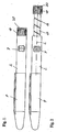
- FIG. 1 shows a device for the dosed administration of a fluid product, for example insulin, an osteoporosis preparation or a growth hormone.
- the device is formed as a slender Injetationspen. It comprises a housing of which a proximal housing section 2 can be seen. A cap 4 covers a distal housing section.
- the device is in an initial state which it takes before the administration of a product dose to be administered or after administration.
- the window 7 is formed as an opening of the housing portion 2 and is covered by a transparent cover, such as a magnifying glass; In principle, the window 7 can also simply be an opening, through which the dose set by means of the dosing member 18 can be read on a dose scale.
- the dose display shows the dose "zero".
- a plate-shaped actuator 30 forms a proximal end of the device.
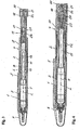
- FIG. 2 shows the device in the same view as FIG. 1 but after adjusting a maximum dose of product per injection with the device.
- the maximum product dose exemplarily corresponds to 80 dosage units of the product.
- the dosing member 18 is formed as a knob. By a Dosierburnfarction the dosing 18, the dose is set. By Dosierburnfar a display drum 17 is rotated out of the housing portion 2 along a central longitudinal axis L of the device. The dose scale is spiral on the outer peripheral surface of the display drum 17 applied circumferentially.
- the display drum 17 is provided circumferentially spirally around the central longitudinal axis L with a thread 19 which is in threaded engagement with a corresponding internal thread of the housing section 2, so that the display drum 17 forms a spindle drive with the housing section 2.
- the pitch of the threaded engagement with respect to the central longitudinal axis L is so great that a self-locking can not occur when the display drum 17 is pressed by pressure against the actuator 30 in the housing portion 2.
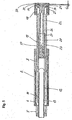
- FIG. 3 shows the device in the state of FIG. 2 , ie in the state of maximum dose setting, in a longitudinal section containing the central longitudinal axis L of the device.
- FIG. 4 shows the device in the state of FIG. 1 , ie in the zero dose setting, in the same longitudinal section.
- FIG. 5 again shows in the same longitudinal section, but enlarged, the proximal part of the device in the state of maximum dose setting.
- the distal housing section 1 and the immovably connected proximal housing section 2 form a housing 1, 2 of the device.
- the distal housing portion 1 forms a receptacle for a product filled with the container 3, which is formed by an ampoule, as it is known for example from the diabetes therapy for injection pens.
- a distal outlet of the ampoule is closed by a septum.
- An injection cannula arranged along the longitudinal axis L projects through the septum.
- a piston is taken along the longitudinal direction L in a conveying direction V to the outlet to be movable.
- the longitudinal axis L also forms a conveying axis of the device and will also be referred to hereafter.
- a piston rod drives the piston along the conveying axis L in the conveying direction V.
- the piston rod forms a first conveying member 11 of a conveying device, which also comprises the piston and also a second conveying member 12 driving the first conveying member 11.
- the first conveying member 11 is in the FIGS. 3, 4 and 5 not shown, the reference numeral "11" indicates the installation site.
- the first conveying member 11 is in threaded engagement with the second conveying member 12, the conveying axis L being the threaded axis.
- the first conveyor member 11 is further engaged with a retainer 5 which is non-movably connected to the housing portion 2 in and against the conveying direction V.
- the retaining device 5 forms two retaining tongues, which engage in longitudinal grooves of the first conveying member 11 and block movement of the first conveying member 11 against the conveying direction V.
- the first conveyor member 11 is provided for the retaining engagement in the two grooves each with a sawtooth row.
- the interaction of the first conveyor member 11 and the retainer 5 corresponds to the known Zahnstangenpens. An example of such a pen will be found in the DE 102 32 411 A1 to which reference is made in this regard.
- the first conveying member 11 is further not rotatable relative to the housing portion 2 about the conveying axis L, wherein a rotation formed for this purpose blocks a rotational movement in both directions of rotation in all operating states of the device.
- the retaining device 5 can simultaneously form the anti-rotation, however, a rotation can also be provided in addition.
- the second conveyor member 12 is sleeve-shaped, surrounds the first conveyor member 11 and has at its distal end an internal thread 13 which is in threaded engagement with an external thread of the first conveyor member 11.
- the internal thread 13 and the external thread of the first conveyor member 11 are fine thread with a correspondingly small thread pitch.
- the second conveyor member 12 also still forms in the distal end region a radially outwardly projecting conveyor stop 14, which forms in cooperation with a counter-stop 6, the pollhalteeim-ichtung 5, the conveying movement of the second conveyor member 12 and thus because of the threaded engagement and the first conveyor member eleventh limited in the conveying direction V.
- the stop 14 may form a circumferential flange or a plurality of individual cams or optionally also only a single cam, if the counter-stop 6 rotates about the conveying axis L.
- the second threaded engagement between the one the display drum 17 and the housing portion 2 is formed, namely between the external thread 19 of the display drum 17 and an internal thread 9 of the housing portion 2.
- the conveying axis L is also the threaded axis of the second thread engagement.
- Between the second conveyor member 12 and the housing portion 2 remains an annular gap, in which the display drum 17 enters the second threaded engagement in the distribution of the product and from which it extends when setting the dose. When driving in and out, it slides over the side of the stop 14 smooth outer surface of the second conveyor member 12.
- the display drum 17 is thus guided radially on both sides, on the one hand in the second threaded engagement 9, 19 and the other by the second conveyor member 12.
- the second conveyor member 12 is connected to the dosing member 18 in a rotationally secured manner for adjusting the dose via a coupling.
- the dosing member 18 and the display drum 17 in turn are formed in one piece as a sleeve body with the display drum 17 as an elongated distal sleeve Abscut and the dosing member 18 as a wider, but axially shorter proximal end portion.
- the clutch comprises a first coupling member 21, a second coupling member 22 and a spring 20 which is formed as a spiral spring and acting as a compression spring, the second coupling member 22 in a clutch engagement with the first coupling member 21 presses.
- the coupling members 21 and 22 are positively secured with respect to the conveying axis L connected to each other.
- the first coupling member 21 is inserted into the dosing member 18 forming sleeve section of Hiilsenköniers 17, 18 and connected to the sleeve body 17, 18 both secured against rotation and axially immovable.
- the first coupling member 21 is cup-shaped with a bottom at the proximal end and a wall projecting from the bottom circumferentially in the distal direction.
- the first coupling member 21 are provided with coupling ribs, cams, grooves 24 or the like and the second coupling member 22 with corresponding counter-grooves, ribs or cams 25 or the like, the interlocking rotational movement of one of the coupling members 21 and 22 relative to prevent the other.
- the clutch engagement it is sufficient for the clutch engagement, of course, only a single pair of, for example, coupling rib 24 and coupling groove 25 as engagement elements.
- the second coupling member 22 is also part of a compensating device, which comprises the coupling member 22 as a first compensating structure and a second compensating structure 23 cooperating therewith.
- the spring 20 also fulfills a dual function, on the one hand as a clutch spring of the clutch and on the other as a compensation spring of the compensation device.
- the two compensation structures 22 and 23 form a telescope. They are linearly guided against rotation in and against the conveying direction V along the conveying axis L, wherein the compensating structure 22 forms an inner and the compensating structure 23 forms an outer telescopic section.
- the compensation structure 22 is provided with filling elements 26 on its outer shell surface and the compensation structure 23 is provided with Fümmmgsneuveijnianan 27 on its Mantelinnenil kaue.
- the guide elements 26 and 27 are formed in the manner of a tongue and groove guide. In principle, the guide could also be formed by means of only a single guide element and a single guide counter-element. As the FIGS. 3 to 5 can recognize, overlap the two compensation structures 22 and 23 each other in the state of zero dose setting almost completely, while the axial overlap in the state of maximum dose setting is minimal and barely the non-rotating connection between the display drum 17 and the metering member 18 on the one hand and the second Conveyor 12 on the other hand guaranteed.
- the compensation structure 23 is cup-shaped with a bottom at the distal end and a sleeve wall rising up from the bottom in the proximal direction.
- the spring 20 is supported in the conveying direction V at the bottom of the compensating structure 23. Furthermore, an axial guidance for the spring 20 projects centrally from the bottom.
- the spring 20 presses the compensation structure 23 in the conveying direction V to stop against the second conveyor member 12.
- the second conveyor member 12 and the compensation structure 23 with each other in a rotationally secured engagement with the conveying axis L.
- the second conveyor member 12 at its proximal End on an inner surface of the shell axially short engagement elements which are formed with counter-elements formed on the outer surface of the outer shroud 23 in the rotationally secured engagement.
- the compensation structure 23 is a separate component in the exemplary embodiment, but may alternatively be molded in one piece with the second delivery member 12. However, the shaping as a separate component is manufacturing technology advantageous.
- the actuator 30 forms a plate-shaped termination of the device.
- a pin-shaped connecting portion through the bottom of the first coupling member 21 into the interior of the dosing member 18 and is anchored there in a bottom portion of the also cup-shaped second coupling member 22, so that the coupling member 22 and the actuator 30 in and are not movable relative to the conveying direction V relative to each other.
- they are rotatable relative to each other about the conveying axis L; In principle, however, they can also be connected to each other without rotation.
- the actuating member 30 is movable together with the second coupling member 22 against the restoring elasticity force of the spring 20 relative to the first coupling member 21 in the conveying direction V. Further, it is rotatable about the conveying axis L at least relative to the first coupling member 21.
- the distance L H is between axially opposite contact surfaces of the actuator 30 and the coupling member 21.
- the contact surface of the actuator 30 is denoted by 31 and is formed around the connecting portion of the actuator 30 centrally as projecting into the distal direction, raised surface.
- a contact element 32 is inserted into the coupling member 21 complementary to the contact surface 31.
- the contact surface 31 and the mating surface of the contact element 32 are formed particularly low friction, for example made of Teflon.
- the device arrives in the state of zero dose setting, such as FIG. 4 it points to the user.
- the full container 3 is inserted.
- the user removes the cap 4 and removes a needle guard surrounding the hypodermic needle.
- the cap 4 Before setting the desired dose, the cap 4 can be replaced for safety reasons.
- the user holds the device in the region of the housing 1, 2 or in the cap 4 attached in any case in the region of the housing portion 2 and twists the dosing member 18 until the desired dose is set. Due to the metering rotational movement, the drum 17 moves out of the housing section 2 in the second threaded engagement 9, 19 in the proximal direction. In window 7, the dose corresponding to the current dosing position can be read.
- the Dosilerburnterrorism takes place in discrete steps between locking positions. It is wahmelunbar with each click a clear click sound wahmelunbar.
- the maximum dose setting is determined by a stop of the display drum 17 and a counter-stop of the housing section 2. Between the two extreme settings of the zero dose and the maximum dose came the dosing member 18 and thus the display drum 17 are rotated in both directions of rotation arbitrarily from one locking position to the next, so that Dosiskon-ectrctures are readily possible.
- the second coupling member 22 is held by the spring 20 permanently in clutch engagement with the first coupling member 21. Furthermore, the coupling member 22 is permanently in rotationally secured engagement with the compensation structure 23 during the metering rotational movement, which in turn is held by the spring 20 in the rotationally secured engagement with the second delivery member 12. The rotational portion of the metering rotational movement is thus transmitted to the second conveyor member 12. Since the first conveying member 11 is not rotatable relative to the housing 1, 2 and is further prevented from the retainer 5 from moving against the conveying direction V, the second conveying member 12 threadably engages the first conveying member 11 relative to the conveying direction V. In this Dosierhub that performs the second conveyor member 12 relative to the first conveyor member 11, the axial distance between the stop 14 and the counter-stop 6. This axial distance corresponds to the length of Dosierhubs and, correspondingly, the length of the delivery.
- the translatory component of the metering movement is longer than the metering stroke of the second conveyor member 12.
- the equalizer 20, 22 and 23 compensates for the difference in length, so that in the clutch engagement between limited by stops extreme settings, the zero dose setting the maximum dose setting, always the non-rotating connection between the display drum 17 and the dosing member 18 on the one hand and the second conveyor member 12 on the other.
- the user removes the cap 4, if this was still plugged for safety reasons, the injection needle pierces the desired piercing point through the skin and places the needle tip in the subcutaneous tissue.
- the maximum dose which in the exemplary embodiment is 80 units ( FIG. 2 )
- the user When subcutaneously placed injection needle, the user holds the device with one hand in the region of the housing 1, 2 and presses with the thumb in the conveying direction V against the actuator 30.
- the second coupling member 22 against the pressure of Spring 20 moves relative to the first coupling member 21 in the conveying direction V from the clutch engagement.
- the axial length of the coupling engagement mediating engagement members 24 and 25 is sized so that the clutch engagement is released when the actuator 30 relative to the coupling member 21 has covered the idle stroke L H.
- Upon further pressure on the actuating element 30 presses this via the contact element 32 against the coupling member 21, so that the display drum 17 in the second phase of the operating stroke in the second threaded engagement 9, 19 screwed into the housing section 2.
- the second coupling member 22 moves telescopically in the compensation structure 23 against an axial stop, which forms the compensation structure 23 in the embodiment by its bottom.
- an axial stop which forms the compensation structure 23 in the embodiment by its bottom.
- further pressure on the actuating element 30 causes the second delivery member 12 to be entrained in the last phase of the operating stroke due to the pressing compensation structure 23 and to execute the delivery stroke.
- the delivery stroke is limited by the pair of stops 6, 14.
- the pressure is taken from the actuator 30, so that the spring 20, the coupling member 22 again in the clutch engagement with the coupling member 21 suppressed.
- the cap 4 is replaced.
- the device is now back in the state of FIG. 4 , but without the existing only before first use needle cap. In this condition, the device is stored until the next injection.
Description
- Die Erfindung betrifft eine Vorrichtung für die Verabreichung eines fluiden Produkts, das insbesondere ein Medikament, ein Diagnosemittel oder ein kosmetisches Produkt sein kann. Bevorzugt wird die Erfindung in der Selbstverabreichung eingesetzt, obgleich sie hierauf nicht beschränkt ist, sondern auch in der Verabreichung durch medizinisch geschultes Personal zum Einsatz gelangen kann.
- In Therapien, in denen medizinisch nicht geschulte Personen einen Wirkstoff verabreichen, beispielsweise sich selbst, müssen die verwendeten Verabreichungsvorrichtungen einfach, aber dennoch sicher handhabbar sein. Insbesondere muss sichergestellt sein, dass bei Vorrichtungen, die eine Einstellung der zu verabreichenden Produktdosis erlauben, die eingestellte Dosis zweifelfrei angezeigt wird. In der Diabetestherapie, einem bevorzugten Verwendungsfeld der Erfindung, ist auch zu berücksichtigen, dass die sich das Insulin selbst verabreichenden Personen sehgeschädigt sein können und die eingestellte Dosis daher besonders deutlich und eindeutig auf einer Dosisskala ablesbar sein sollte. Der guten Ablesbarkeit zuträglich ist es, wenn die Dosisskala auf einer Anzeigetrommel aufgetragen ist, die rotatorisch und translatorisch bewegbar ist, da die Dosisskala in diesem Fall längs und in Drehrichtung der Anzeigetrommel erstreckt werden kann.
- Vorrichtungen der genannten Art sind beispielsweise aus der
WO 99/38554 A1 - Die
WO 2004/078239 A1 offenbart eine Verabreichungsvorrichtung mit Anzeigetrommel bestehend aus einem ersten Förderglied, das mit einem zweiten Förderglied in einem ersten Gewindeeingriff steht, und einer Anzeigetrommel, die mit einem inneren Gehäuseteil in einem zweiten Gewindeeingriff steht, wobei beide Gewindeeingriffe die gleiche Gewindesteigung aufweisen. - Aus der
WO 03/075985 A1 WO 99/38554 - Aus der
US 2002/0052578 A1 ist eine Verabreichungsvorrichtung mit den Merkmalen a) bis f) des Anspruchs 1 bekannt. Das Betätigungselement dieser Verabreichungsvorrichtung ist mit dem zweiten Kupplungsglied verbunden, so dass das zweite Kupplungsglied und das Betätigungselement in und gegen die Förderrichtung relativ zueinander nicht beweglich sind. Das Betätigungselement ist relativ zum ersten Kupplungsglied der Verabreichungsvorrichtung um die Förderachse drehbar. - Es ist eine Aufgabe der Erfindung, bei einer Verabreichungsvorrichtung der genannten Art die bei Betätigung auftretende Reibung zu vermindern.
- Die Aufgabe wird durch den Gegenstand des Anspruchs 1 gelöst.
- Die Erfindung betrifft eine Vorrichtung zur Verabreichung eines fluiden Produkts, die ein Gehäuse mit einer Aufnahme für das Produkt, eine Fördereinrichtung zur Förderung des Produkts und eine Dosiereinrichtung für die Einstellung einer zu verabreichenden Produktdosis und Anzeigen der eingestellten Produktdosis umfasst. Das Gehäuse bildet eine Aufnahme für das Produkt, vorzugsweise eine Aufnahme für ein mit dem Produkt gefülltes Behältnis. Grundsätzlich könnte die Aufnahme jedoch auch selbst unmittelbar das Produktbehältnis bilden. Die Fördereinrichtung umfasst ein erstes Förderglied, das relativ zu dem Gehäuse in eine Förderrichtung bewegbar ist, um die eingestellte Produktdosis in einem entsprechend der Produktdosis voreingestellten Förderhub auszuschütten. Bei dem Förderhub handelt es sich vorzugsweise um eine translatorische Bewegung des ersten Förderglieds in die Förderrichtung, vorzugsweise um eine Linearbewegung entlang einer Förderachse. Das erste Förderglied kann insbesondere als Kolbenstange gebildet sein, die in solch einer Ausbildung mit einem Kolben der Fördereinrichtung verbunden ist, beispielsweise mit dem Kolben in einem Stück gebildet oder mit dem Kolben verschraubt oder verschnappt ist, oder bei dem Förderhub lose gegen eine Rückseite des Kolbens drückt. Die Fördereinrichtung umfasst ferner ein zweites Förderglied, das mit dem ersten Förderglied in einem ersten Gewindeeingriff ist, in dem es für die Einstellung der Produktdosis relativ zu dem ersten Förderglied und dem Gehäuse drehbar und für die Ausschüttung der eingestellten Produktdosis relativ zu dem Gehäuse in die Förderrichtung translatorisch bewegbar ist. Falls die Fördereinrichtung für die Förderung des Produkts einen axial bewegbaren Kolben aufweist, wie dies bevorzugt wird, kann das erste Förderglied insbesondere eine Kolbenstange bilden. In derartigen Ausführungen kann das erste Förderglied grundsätzlich aber auch nur ein Übertragungsglied sein, das eine Förderbewegung des zweiten Förderglieds erst auf eine Kolbenstange überträgt.
- Die Anzeigetrommel ist in einem zweiten Gewindeeingriff relativ zu dem Gehäuse drehbar sowie in und gegen die Förderrichtung translatorisch bewegbar. Vorzugsweise ist die Anzeigetrommel mit dem Gehäuse oder einer mit dem Gehäuse verbundenen Zwischenstruktur in dem zweiten Gewindeeingriff. Falls der zweite Gewindeeingriff mit einer Zwischenstruktur gebildet ist, ist die Zwischenstruktur mit dem Gehäuse vorzugsweise so verbunden, dass sie sich entweder bei der Einstellung der Dosis oder bei der Förderbewegung oder vorzugsweise in beiden Fällen relativ zu dem Gehäuse nicht bewegt.
- Nach der Erfindung umfasst die Vorrichtung ferner eine Kupplung, welche die Anzeigetrommel mit dem zweiten Förderglied verdrehgesichert koppelt, wobei der für die verdrehsichere Kopplung von der Kupplung gebildete Kupplungseingriff sich automatisch löst, wenn die Vorrichtung für die Verabreichung betätigt wird. Vorteilhafterweise wird der Kupplungseingriff gelöst bevor der Förderhub des zweiten Förderglieds einsetzt. Indem das zweite Förderglied relativ zu dem Gehäuse in und gegen die Förderrichtung bewegbar ist, mit dem ersten Förderglied einen ersten Spindeltrieb bildet und während der Einstellung der Produktdosis über einen lösbaren Kupplungseingriff mit der Anzeigetrommel gekoppelt ist, können die Gewindesteigungen der beiden Spindeltriebe, nämlich der mit dem zweiten Förderglied gebildete erste Spindeltrieb und der mit der Anzeigetrommel gebildete zweite Spindeltrieb, zueinander auf einfache Weise in weiten Grenzen variiert werden, wobei die Gewindesteigung des zweiten Gewindeeingriffs größer ist als die Gewindesteigung des ersten Gewindeeingriffs. So kann der mit der Anzeigetrommel gebildete Spindeltrieb insbesondere eine große Gewindesteigung und der mit dem zweiten Förderglied gebildete Spindeltrieb eine besonders kleine Gewindesteigung aufweisen. Es wird somit ein kleiner Förderhub mit einem großen Anzeigehub kombiniert werden. So kann die Gewindesteigung im zweiten Gewindeeingriff beispielsweise drei-, vier- oder fünfmal so groß sein wie die Gewindesteigung im ersten Gewindeeingriff.
- Der Gewindeeingriff der Förderglieder ist vorzugsweise selbsthemmend, was vorteilhaftenveise dadurch erreicht wird, dass die Steigung der im Gewindeeingriff befindlichen Gewinde ausreichend klein ist. Stattdessen oder zusätzlich kann das zweite Förderglied durch einen lösbaren Rasteingriff an einer unerwünschten Drehbewegung während des Förderhubs gehindert werden. Der Winkelabstand der Drehrastpositionen solch eines Rasteingriffs entspricht der Vergrößerung oder Verkleinerung der Dosis um eine einstellbare Einheit.
- Die Kupplung wird mittels einer Feder in den Kupplungseingriff gespannt und umfasst hierfür ein erstes Kupplungsglied und ein zweites Kupplungsglied sowie die Feder, welche die Kupplungsglieder miteinander in den Kupplungseingriff spannt. Zumindest in Ausgestaltungen, in denen die für die Ausführung des Förderhubs erforderliche Kraft manuell aufgebracht wird, wird es bevorzugt, wenn der Kupplungseingriff durch die für den Förderhub aufzubringende Kraft gelöst wird. Vorteilhafterweise wird die den Förderhub bewirkende Betätigungskraft in die Förderrichtung ausgeübt, und die Feder spannt eines der Kupplungsglieder in oder vorzugsweise gegen die Förderrichtung in den Kupplungseingriff mit dem anderen. Der Kupplungseingriff, d.h. die durch die Kupplungsglieder hergestellte Verdrehsicherung, kann rein auf einem Reibschluss beruhen, vorzugsweise beruht sie jedoch auf Formschluss oder umfasst zumindest eine Formschlussverbindung der Kupplungsglieder. Der Kupplungseingriff wird vorzugsweise durch eine in die Förderrichtung erfolgende Bewegung, die eines der Kupplungsglieder relativ zu dem anderen ausführt, gelöst. Vorteilhafterweise ist eines der Kupplungsglieder relativ zu dem anderen in die Förderrichtung längs der Förderachse aus dem Kupplungseingriff bewegbar.
- Für die Betätigung umfasst die Vorrichtung ein Betätigungselement, durch dessen Betätigung der Kupplungseingriff gelöst wird. Wenigstens eines aus Anzeigetrommel und zweitem Förderglied, vorzugsweise die Anzeigetrommel und noch bevorzugter auch das zweite Förderglied, ist relativ zu dem Betätigungselement drehbar. Das Betätigungselement ist vorzugsweise permanent mit einem der beiden Kupplungsglieder verbunden. Vorzugsweise ist es in und gegen eine Richtung, in die das betreffende Kupplungsglied aus dem Kupplungseingriff bewegt wird, nicht beweglich mit dem betreffenden Kupplungsglied verbunden. Bei der Betätigung gelangt das Betätigungselement vorzugsweise gegen das andere der Kupplungsglieder in einen Kontakt. Das Betätigungselement und das andere der Kupplungsglieder bilden für den Kontakt vorzugsweise reibarme Kontaktflächen um einer im Betätigungskontakt möglicherweise auftretenden Relativdrehung nur geringe Reibungskräfte entgegenzusetzen.
- Die Feder der Kupplung ist vorzugsweise eine mechanische Feder. Sie wirkt vorteilhafterweise als Druckfeder. Alternativ kann sie aber beispielsweise auch als Zugfeder wirken, welche die Kupplungsglieder mit ihrer Federkraft in den Kupplungseingriff zieht. In der bevorzugten Ausbildung als Druckfeder wirkt sie zum einen gegen eines der Kupplungsglieder und zum anderen vorzugsweise gegen das zweite Förderglied. Als Druckfeder kann sie alternativ auch als Druckgasfeder, beispielsweise Druckluftfeder, gebildet sein.
- In bevorzugten Ausführungen ist eine Ausgleichseinrichtung vorgesehen, die in Förderrichtung längenvariabel ist und das zweite Förderglied mit der Anzeigetrommel verdrehgesichert verbindet, wenn der Kupplungseingriff besteht. Die Ausgleichseinrichtung umfasst bevorzugterweise eine Feder, die so angeordnet ist, dass die Länge der Ausgleichseinrichtung nur gegen eine rückstellende Elastizitätskraft der Feder verringerbar ist. Die Feder ist vorzugsweise als mechanische Feder gebildet, könnte grundsätzlich aber auch eine pneumatische Feder sein. Das zu der Feder der Kupplung gesagte gilt für die Feder der Ausgleichseinrichtung ebenfalls. Die Feder kann insbesondere die im Zusammenhang mit der Kupplung beschriebene Feder sein. Obgleich weniger bevorzugt, kann die dem Längenausgleich dienende Feder aber auch zusätzlich zu der Feder der Kupplung vorgesehen sein.
- Die Ausgleichseinrichtung umfasst bevorzugterweise wenigstens zwei in Förderrichtung einander überlappende und relativ zueinander verdrehgesichert geführte Ausgleichsstrukturen. Vorzugsweise sind die wenigstens zwei Ausgleichsstrukturen unmittelbar aneinander verdrehgeführt. Bei bestehendem Kupplungseingriff ist eine der Ausgleichsstrukturen mit der Anzeigetrommel und die andere mit dem zweiten Förderglied verdrehgesichert verbunden. Die Ausgleichseinrichtung ist in bevorzugten Ausführungen als Teleskop gebildet. Die Ausgleichsstmkturen bilden in derartigen Ausführungen je einen in Förderrichtung erstreckten Teleskopabschnitt. Die Feder der Ausgleichseinrichtung stützt sich in vorteilhaften Ausbildungen in die Förderrichtung an der einen und gegen die Förderrichtung an der anderen der Ausgleichsstrukturen ab, so dass die Federkraft trachtet, die Ausgleichsstrukturen auseinander zu treiben. Bevorzugt weist die Ausgleichseimichtung nur genau zwei in Förderrichtung relativ zueinander bewegbare Ausgleichsstrukturen auf. Die Ausgleichsstnikturen sind in sich in Förderrichtung vorteilhafterweise steif, könnten aber auch selbst in Förderrichtung eine Elastizität aufweisen, so dass sogar auf eine separate Feder verzichtet werden könnte. So könnte die Ausgleichseinrichtung durchaus als Federbalg gebildet sein, der gleichzeitig auch eines der Kupplungsglieder bilden kann.
- Die Ausgleichseinrichtung ist besonders vorteilhaft in Kombination mit der Kupplung. Sie ist für eine Aufrechterhaltung der verdrehgesicherten Verbindung zwischen der Anzeigetrommel und dem zweiten Förderglied aber auch als solche bereits vorteilhaft, d.h. für eine Vorrichtung, die zwar die Merkmale a) bis d), nicht jedoch das Merkmal e) von Anspruch 1 aufweist.
- In bevorzugter Ausführung umfasst die Vorrichtung eine Führung für eine verdrehgesicherte Linearführung des ersten Förderglieds in Förderrichtung. Auf ein im Förderstrang nachgeordnetes Förderglied, beispielsweise einen Kolben, kann von solch einem ersten Förderglied vorteilhafterweise kein Drehmoment übertragen werden.
- Bevorzugterweise ist eine Rückhalteeinrichtung vorgesehen, die in einem Eingriff mit dem ersten Förderglied eine Bewegung des ersten Förderglieds gegen die Förderrichtung verhindert. Die Rückhalteeinrichtung und das erste Förderglied, soweit sein Zusammenwirken mit der Rückhalteeinrichtung betroffen ist, können insbesondere wie von Zahnstangenpens her bekannt gebildet sein. So kann das erste Förderglied beispielsweise als Zahnstange mit wenigstens einer Sägezahnreihe gebildet sein, in welche die Rückhalteeinrichtung mit einer federnd biegbaren Rückhaltezunge eingreifend eine Bewegung des ersten Förderglieds gegen die Förderrichtung verhindert, die Bewegung in die Fördewichtung jedoch zulässt.
- Die Vorrichtung kann insbesondere ein Injektionsgerät sein, vorteilhafterweise für subkutane Verabreichungen mittels Injektionsnadel oder auch für nadellose Druckinjektoren. Das Injektionsgerät ist bevorzugt ein Injektionspen. Wie bereits in Verbindung mit der Rückhalteeinrichtung erwähnt, kann die Vorrichtung in der Art eines Zahnstangenpens gebildet sein, wobei das erste Förderglied allerdings als kombinierte Zahn-Gewinde-Stange gebildet ist oder zumindest einen entsprechenden Abschnitt aufweist. Aufgrund ihres einfachen Aufbaus und daher günstigen Preises bietet sich die Vorrichtung auch als Einweggerät an, das nach Entleerung des Produktbehältnisses entsorgt wird.
- Bevorzugte Merkmale der Erfindung werden auch in den Unteransprüchen und deren Kombinationen beschrieben.
- Ein Ausführungsbeispiel der Erfindung wird nachfolgend anhand von Figuren erläutert. An dem Ausführungsbeispiel offenbar werdende Merkmale bilden je einzeln und in jeder Merkmalskombination die Gegenstände der Ansprüche und auch die vorstehend beschriebenen Ausgestaltungen vorteilhaft weiter. Es zeigen:
- Figur 1
- eine erfindungsgemäße Vorrichtung in einem Zustand der Nulldosis-Einstellung in einer Ansicht auf eine Dosisanzeige,
- Figur 2
- die Vorrichtung in einem Zustand der Maximaldosis-Einstellung in der Ansicht auf die Dosisanzeige,
- Figur 3
- die Vorrichtung im Zustand der Maximaldosis-Einstellung in einem. Längsschnitt,
- Figur 4
- die Vorrichtung im Zustand der Nulldosis-Einstellung im gleichen Längsschnitt und
- Figur 5
- einen proximalen Abschnitt der Vorrichtung in einem Zustand der Maximaldosis-Einstellung in dem Längsschnitt der
Figuren 3 und 4 . -
Figur 1 zeigt eine Vorrichtung für die dosierte Verabreichung eines fluiden Produkts, beispielsweise Insulin, ein Osteoporosepräparat oder ein Wachstumshormon. Die Vorrichtung ist als schlanker Injektionspen gebildet. Sie umfasst ein Gehäuse, von dem ein proximaler Gehäuseabschnitt 2 erkennbar ist.. Eine Kappe 4 deckt einen distalen Gehäuseabschnitt ab. Die Vorrichtung befindet sich in einem Ausgangszustand, den sie vor Einstellung einer zu verabreichenden Produktdosis oder nach der Verabreichung einnimmt. Zu erkennen ist ein Dosierglied 18 für die Einstellung der Produktdosis und eine Dosisanzeige mit einem Fenster 7. Das Fenster 7 ist als Durchbrechung des Gehäuseabschnitts 2 gebildet und wird von einer durchsichtigen Abdeckung, beispielsweise eine Lupe abgedeckt; grundsätzlich kann das Fenster 7 auch einfach nur eine Durchbrechung sein, durch dies auf einer Dosisskala die mittels des Dosierglieds 18 eingestellte Dosis ablesbar ist. Im Ausgangszustand derFigur 1 zeigt die Dosisanzeige die Dosis "Null" an. Ein tellerförmiges Betätigungselement 30 bildet ein proximales Ende der Vorrichtung. -
Figur 2 zeigt die Vorrichtung in der gleichen Ansicht wieFigur 1 , allerdings nach Einstellung einer mit der Vorrichtung pro Injektion maximal verabreichbaren Produktdosis. Wie an der Dosisanzeige ablesbar, entspricht die maximale Produktdosis beispielhaft 80 Dosiseinheiten des Produkts. Das Dosierglied 18 ist als Drehknopf gebildet. Durch eine Dosierdrehbewegung des Dosierglieds 18 wird die Dosis eingestellt. Durch die Dosierdrehbewegung wird eine Anzeigetrommel 17 längs einer zentralen Längsachse L der Vorrichtung aus dem Gehäuseabschnitt 2 herausgedreht. Die Dosisskala ist auf der äußeren Umfangsfläche der Anzeigetrommel 17 spiralig umlaufend aufgetragen. Die Anzeigetrommel 17 ist um die zentrale Längsachse L spiralig umlaufend mit einem Gewinde 19 versehen, das mit einem entsprechenden Innengewinde des Gehäuseabschnitts 2 in einem Gewindeeingriff steht, so dass die Anzeigetrommel 17 mit dem Gehäuseabschnitt 2 einen Spindeltrieb bildet. Die Steigung des Gewindeeingriffs bezüglich der zentralen Längsachse L ist so groß, dass eine Selbsthemmung nicht auftreten kann, wenn die Anzeigetrommel 17 durch Druck gegen das Betätigungselement 30 in den Gehäuseabschnitt 2 gedrückt wird. -
Figur 3 zeigt die Vorrichtung im Zustand derFigur 2 , d.h. im Zustand der Maximaldosis-Einstellung, in einem Längsschnitt, der die zentrale Längsachse L der Vorrichtung enthält.Figur 4 zeigt die Vorrichtung im Zustand derFigur 1 , d.h. in der Nulldosis-Einstellung, im gleichen Längsschnitt.Figur 5 zeigt wiederum im gleichen Längsschnitt, jedoch vergrößert, den proximalen Teil der Vorrichtung im Zustand der Maximaldosis-Einstellung. - Der distale Gehäuseabschnitt 1 und der damit unbeweglich verbundene proximale Gehäuseabschnitt 2 bilden ein Gehäuse 1, 2 der Vorrichtung. Der distale Gehäuseabschnitt 1 bildet eine Aufnahme für ein mit dem Produkt gefülltes Behältnis 3, das von einer Ampulle gebildet wird, wie sie beispielsweise aus der Diabetestherapie für Injektionspens bekannt ist. Ein distaler Auslass der Ampulle wird von einem Septum verschlossen. Eine längs der Längsachse L angeordnete Injektionskanüle durchragt das Septum. In dem Behältnis 3 ist ein Kolben längs der Längsrichtung L in eine Förderrichtung V auf den Auslass zu bewegbar aufgenommen. Die Längsachse L bildet auch eine Förderachse der Vorrichtung und wird im folgenden auch so bezeichnet.
- Eine Kolbenstange treibt den Kolben längs der Förderachse L in die Förderrichtung V. Die Kolbenstange bildet ein erstes Förderglied 11 einer Fördereinrichtung, die auch den Kolben und ferner ein das erste Förderglied 11 antreibendes zweites Förderglied 12 umfasst. Das erste Förderglied 11 ist in den
Figuren 3, 4 und5 nicht eingezeichnet, das Bezugszeichen "11" deutet auf den Einbauort. Das erste Förderglied 11 ist mit dem zweiten Förderglied 12 in einem Gewindeeingriff, wobei die Förderachse L die Gewindeachse ist. Das erste Förderglied 11 ist des weiteren mit einer Rückhalteeinrichtung 5 in einem Eingriff, die in und gegen die Förderrichtung V nicht beweglich mit dem Gehäuseabschnitt 2 verbunden ist. Die Rückhalteeinrichtung 5 bildet zwei Rückhaltezungen, die in Längsnuten des ersten Förderglieds 11 eingreifen und eine Bewegung des ersten Förderglieds 11 gegen der Förderrichtung V blockieren. Das erstes Förderglied 11 ist für den Rückhalteeingriff in den beiden Nuten je mit einer Sägezahnreihe versehen. Das Zusammenwirken des ersten Förderglieds 11 und der Rückhalteeinrichtung 5 entspricht dem bekannter Zahnstangenpens. Ein Beispiel eines derartigen Pens wird in derDE 102 32 411 A1 beschrieben, auf die diesbezüglich verwiesen sei. - Das erste Förderglied 11 ist des weiteren relativ zu dem Gehäuseabschnitt 2 um die Förderachse L nicht drehbar, wobei eine hierfür gebildete Verdrehsicherung eine Drehbewegung in beide Drehrichtungen in allen Betriebszuständen der Vorrichtung blockiert. Die Rückhalteeinrichtung 5 kann gleichzeitig auch die Verdrehsicherung bilden, eine Verdrehsicherung kann jedoch auch zusätzlich vorgesehen sein.
- Das zweite Förderglied 12 ist hülsenfönnig, umgibt das erste Förderglied 11 und weist an seinem distalen Ende ein Innengewinde 13 auf, das mit einem Außengewinde des ersten Förderglieds 11 in dem Gewindeeingriff ist. Das Innengewinde 13 und das Außengewinde des ersten Förderglieds 11 sind Feingewinde mit einer entsprechend geringen Gewindesteigung. Das zweite Förderglied 12 bildet ebenfalls noch im distalen Endbereich einen nach radial außen abragenden Förderanschlag 14, der im Zusammenwirken mit einem Gegenanschlag 6, den die Rückhalteeim-ichtung 5 bildet, die Förderbewegung des zweiten Förderglieds 12 und damit wegen des Gewindeeingriffs auch des ersten Förderglieds 11 in die Förderrichtung V begrenzt. Den Anschlag 14 kann ein umlaufender Flansch oder eine Mehrzahl einzelner Nocken oder gegebenenfalls auch nur ein einzelner Nocken bilden, falls der Gegenanschlag 6 um die Förderachse L umläuft.
- Über den Gewindeeingriff der Förderglieder 11 und 12 hinaus ist als weiterer, zweiter Gewindeeingriff derjenige zwischen der Anzeigetrommel 17 und dem Gehäuseabschnitt 2 gebildet, nämlich zwischen dem Außengewinde 19 der Anzeigetrommel 17 und einem Innengewinde 9 des Gehäuseabschnitts 2. Die Förderachse L ist auch die Gewindeachse des zweiten Gewindeeingriffs. Zwischen dem zweiten Förderglied 12 und dem Gehäuseabschnitt 2 verbleibt ein Ringspalt, in den die Anzeigetrommel 17 im zweiten Gewindeeingriff bei der Ausschüttung des Produkts einfährt und aus dem sie bei der Einstellung der Dosis ausfährt. Beim Ein- und Ausfahren gleitet sie über die von dem Anschlag 14 abgesehen glatte Mantelaußenfläche des zweiten Förderglieds 12. Die Anzeigetrommel 17 ist somit radial beidseitig geführt, zum einen im zweiten Gewindeeingriff 9, 19 und zum anderen durch das zweite Förderglied 12. Indem die Anzeigetrommel 17 das zweite Förderglied 12 eng anliegend umgibt, kann der Pen sehr schlank gehalten werden.
- Das zweite Förderglied 12 ist für die Einstellung der Dosis über eine Kupplung verdrehgesichert mit dem Dosierglied 18 verbunden. Das Dosierglied 18 und die Anzeigetrommel 17 wiederum sind in einem Stück als Hülsenkörper gebildet mit der Anzeigetrommel 17 als langgestreckter distaler Hülsenabsclnitt und dem Dosierglied 18 als demgegenüber breiterer, aber axial kürzerer proximaler Endabschnitt.
- Die Kupplung umfasst ein erstes Kupplungsglied 21, ein zweites Kupplungsglied 22 und eine Feder 20, die als Spiralfeder gebildet ist und als Druckfeder wirkend das zweite Kupplungsglied 22 in einen Kupplungseingriff mit dem ersten Kupplungsglied 21 drückt. Im Kupplungseingriff sind die Kupplungsglieder 21 und 22 formschlüssig bezüglich der Förderachse L verdrehgesichert miteinander verbunden. Das erste Kupplungsglied 21 ist in den das Dosierglied 18 bildenden Hülsenabsclnitt des Hiilsenköniers 17, 18 eingesetzt und mit dem Hülsenkörper 17, 18 sowohl verdrehgesichert als auch axial unbeweglich verbunden. Das erste Kupplungsglied 21 ist topfformig mit einem Boden am proximalen Ende und einer von dem Boden umlaufend in die distale Richtung aufragenden Wand geformt. Es schließt somit den Hülsenkörper 17, 18 an dessen proximalen Ende ab. Für den Kupplungseingriff sind das erste Kupplungsglied 21 mit Kupplungsrippen, -nocken, -nuten 24 oder dergleichen und das zweite Kupplungsglied 22 mit entsprechenden Gegennuten, -rippen oder-nocken 25 oder dergleichen ausgestattet, die ineinandergreifend eine Drehbewegung eines der Kupplungsglieder 21 und 22 relativ zu dem anderen verhindern. Grundsätzlich genügt für den Kupplungseingriff natürlich auch nur ein einziges Paar aus beispielsweise Kupplungsrippe 24 und Kupplungsnut 25 als Eingriffselemente.
- Das zweite Kupplungsglied 22 ist in Doppelfunktion auch Bestandteil einer Ausgleichseinrichtung, welche das Kupplungsglied 22 als eine erste Ausgleichsstruktur und eine damit zusammenwirkende zweite Ausgleichsstruktur 23 umfasst. Auch die Feder 20 erfüllt eine Doppelfunktion, zum einen als Kupplungsfeder der Kupplung und zum anderen als Ausgleichsfeder der Ausgleichseinrichtung. Die beiden Ausgleichsstrukturen 22 und 23 bilden ein Teleskop. Sie sind in und gegen die Förderrichtung V längs der Förderachse L aneinander verdrehgesichert linear geführt, wobei die Ausgleichsstruktur 22 einen inneren und die Ausgleichsstruktur 23 einen äußeren Teleskopabschnitt bildet. Für die Verdrehsicherung ist die Ausgleichsstruktur 22 an ihrer Mantelaußenfläche mit Fülu-ungselementen 26 und die Ausgleichsstruktur 23 an ihrer Mantelinneniläche mit Fühnmgsgegenelementen 27 versehen. Die Führungselemente 26 und 27 sind in der Art einer Nut- und Federführung gebildet. Im Grunde könnte die Führung auch mittels nur einem einzigen Führungselement und einem einzigen Führungsgegenelement gebildet sein. Wie die
Figuren 3 bis 5 erkennen lassen, überlappen die beiden Ausgleichstrukturen 22 und 23 einander im Zustand der Nulldosis-Einstellung nahezu vollständig, während die axiale Überlappung im Zustand der Maximaldosis-Einstellung minimal ist und gerade noch die verdrehgesicherte Verbindung zwischen der Anzeigetrommel 17 und dem Dosierglied 18 einerseits und dem zweiten Förderglied 12 andererseits gewährleistet. Die Ausgleichsstruktur 23 ist topfförniig mit einem Boden am distalen Ende und einer von dem Boden umlaufend in die proximale Richtung aufrageliden Hülsenwand. Die Feder 20 stützt sich in die Förderrichtung V an dem Boden der Ausgleichsstruktur 23 ab. Von dem Boden ragt ferner zentral eine Axialführung für die Feder 20 auf. Die Feder 20 drückt die Ausgleichsstruktur 23 in Förderrichtung V auf Anschlag gegen das zweite Förderglied 12. Ferner sind das zweite Förderglied 12 und die Ausgleichsstruktur 23 miteinander in einem verdrehgesicherten Eingriff bezüglich der Förderachse L. Für den verdrehgesicherten Eingriff weist das zweite Förderglied 12 an seinem proximalen Ende an einer Mantelinnenfläche axial kurze Eingriffselemente auf, die mit an der Mantelaußenfläche der Ausgleichsstruktur 23 gebildeten Gegenelementen in dem verdrehgesicherten Eingriff sind. Die Ausgleichsstruktur 23 ist im Ausführungsbeispiel ein separates Bauteil, sie kann alternativ jedoch in einem Stück mit dem zweiten Förderglied 12 geformt sein. Die Formung als separates Bauteil ist fertigungstechnisch jedoch vorteilhaft. - Das Betätigungselement 30 bildet einen tellerförmigen Abschluss der Vorrichtung. Von der tellerförmigen Struktur ragt in Förderrichtung V ein stiftförmiger Verbindungsabschnitt durch den Boden des ersten Kupplungsglieds 21 in das Innere des Dosierglieds 18 hinein und ist dort in einem Bodenabschnitt des ebenfalls topfförmigen zweiten Kupplungsglieds 22 verankert, so dass das Kupplungsglied 22 und das Betätigungselement 30 in und gegen die Förderrichtung V relativ zueinander nicht beweglich sind. Vorzugsweise sind sie relativ zueinander um die Förderachse L drehbar; grundsätzlich können sie jedoch auch verdrehgesichert miteinander verbunden sein. Das Betätigungselement 30 ist gemeinsam mit dem zweiten Kupplungsglied 22 gegen die rückstellende Elastizitätskraft der Feder 20 relativ zu dem ersten Kupplungsglied 21 in die Förderrichtung V bewegbar. Ferner ist es zumindest relativ zu dem ersten Kupplungsglied 21 um die Förderachse L drehbar.
- Wie am besten in
Figur 5 zu erkennen ist, verbleibt von dem Verbindungsabschnitt des Betätigungselements 30 abgesehen zwischen dem Betätigungselement 30 und dem ersten Kupplungsglied 21 axial ein lichter Abstand LH. Der Abstand LH besteht zwischen einander axial gegenüberliegenden Kontaktflächen des Betätigungselements 30 und des Kupplungsglieds 21. Die Kontaktfläche des Betätigungselements 30 ist mit 31 bezeichnet und ist um den Verbindungsabschnitt des Betätigungselements 30 zentral als in die distale Richtung aufragende, erhabene Fläche gebildet. Zur Bildung der Kontaktgegenfläche ist in das Kupplungsglied 21 komplementär zur Kontaktfläche 31 ein Kontaktelement 32 eingesetzt. Die Kontaktfläche 31 und die Gegenfläche des Kontaktelements 32 sind besonders reibarm gebildet, beispielsweise aus Teflon. - Nachfolgend wird die Funktion der Vorrichtung bei der Einstellung der Dosis und deren Verabreichung anhand der
Figuren 3 und 4 beschrieben, wobei stets auch aufFigur 5 verwiesen sei: - Die Vorrichtung gelangt im Zustand der Nulldosis-Einstellung, wie
Figur 4 ihn zeigt, zum Benutzer. In der Aufnahme des distalen Gehäuseabschnitts 1 ist das volle Behältnis 3 eingesetzt. Für eine erste Injektion zieht der Benutzer die Kappe 4 ab und entfernt einen die Injektionsnadel umgebenden Nadelschutz. - Vor Einstellung der gewünschten Dosis kann aus Sicherheitsgründen wieder die Kappe 4 aufgesteckt werden. Zum Einstellen der Dosis hält der Benutzer die Vorrichtung im Bereich des Gehäuses 1, 2 oder bei aufgesetzter Kappe 4 jedenfalls im Bereich des Gehäuseabschnitts 2 und verdreht das Dosierglied 18, bis die gewünschte Dosis eingestellt ist. Aufgrund der Dosierdrehbewegung fährt die Trommel 17 im zweiten Gewindeeingriff 9, 19 in die proximale Richtung aus dem Gehäuseabschnitt 2 heraus. Im Fenster 7 ist die der momentanen Dosierposition entsprechende Dosis ablesbar. Die Dosilerdrehbewegung erfolgt in diskreten Schritten zwischen Rastpositionen. Dabei ist bei jedem Rastvorgang ein deutliches Klickgeräusch wahmelunbar. Die Maximaldosis-Einstellung wird durch einen Anschlag der Anzeigetrommel 17 und einen Gegenanschlag des Gehäuseabschnitts 2 bestimmt. Zwischen den beiden Extremeinstellungen der Nulldosis und der Maximaldosis kam das Dosierglied 18 und damit gemeinsam die Anzeigetrommel 17 in beide Drehrichtungen beliebig von einer Rastposition in die nächste verdreht werden, so dass Dosiskon-ekturen ohne weiteres möglich sind.
- Bei dem Ausfahren von Anzeigetrommel 17 und Dosierglied 18 wird das zweite Kupplungsglied 22 von der Feder 20 permanent im Kupplungseingriff mit dem ersten Kupplungsglied 21 gehalten. Ferner ist das Kupplungsglied 22 während der Dosierdrehbewegung permanent im verdrehgesicherten Eingriff mit der Ausgleichsstruktur 23, die ihrerseits von der Feder 20 im verdrehgesicherten Eingriff mit dem zweiten Förderglied 12 gehalten wird. Der rotatorische Anteil der Dosierdrehbewegung wird somit auf das zweite Förderglied 12 übertragen. Da das erste Förderglied 11 relativ zu dem Gehäuse 1, 2 nicht drehbar ist und ferner von der Rückhalteeinrichtung 5 an einer Bewegung gegen die Förderrichtung V gehindert wird, schraubt sich das zweite Förderglied 12 im Gewindeeingriff mit dem ersten Förderglied 11 relativ zu diesem gegen die Förderrichtung V. Bei diesem Dosierhub, den das zweite Förderglied 12 relativ zu dem ersten Förderglied 11 ausführt, verändert sich der axiale Abstand zwischen dem Anschlag 14 und dem Gegenanschlag 6. Dieser axiale Abstand entspricht der Länge des Dosierhubs und entsprechend auch der Länge des Förderhubs.
- Da die Gewindesteigung im zweiten Gewindeeingriff 9, 19 größer ist als im Gewindeeingriff der Förderglieder 11 und 12, im ausgeführten Gerät etwas mehr als viermal so groß, absolviert die Anzeigetrommel 17 bei der Dosiseinstellung bei gleichem Drehwinkel einen entsprechend dem Verhältnis der Steigungen längeren Hub. Entsprechend groß und ausreichend voneinander beabstandet sind die Dosiswerte auf der Dosisskala.
- Der axiale Dosierhub der Anzeigetrommel 17 und des Dosierglieds 18, d.h. der translatorische Anteil der Dosierbewegung, ist länger als der Dosierhub des zweiten Förderglieds 12. Die Ausgleichseinrichtung 20, 22 und 23 gleicht die Längendifferenz aus, so dass im Kupplungseingriff zwischen den durch Anschläge begrenzten Extremeinstellungen, der Nulldosis-Einstellung der Maximaldosis-Einstellung, stets die verdrehgesicherte Verbindung zwischen der Anzeigetrommel 17 und dem Dosierglied 18 einerseits und dem zweiten Förderglied 12 andererseits besteht.
- Nachdem die gewünschte Dosis eingestellt ist, beispielsweise die Maximaldosis, die im Ausführungsbeispiel 80 Einheiten beträgt (
Figur 2 ), zieht der Benutzer die Kappe 4 ab, falls diese aus Sicherheitsgründen noch aufgesteckt war, sticht die Injektionsnadel an der gewünschten Einstechstelle durch die Haut und platziert die Nadelspitze so im subkutanen Gewebe. - Bei subkutan platzierter Injektionsnadel hält der Benutzer die Vorrichtung mit einer Hand im Bereich des Gehäuses 1, 2 und drückt mit dem Daumen in Förderrichtung V gegen das Betätigungselement 30. Durch den Druck wird in einer ersten Phase des Bestätigungshubs das zweite Kupplungsglied 22 gegen den Druck der Feder 20 relativ zu dem ersten Kupplungsglied 21 in Förderrichtung V aus dem Kupplungseingriff bewegt. Die axiale Länge der den Kupplungseingriff vermittelnden Eingriffselemente 24 und 25 ist so bemessen, dass der Kupplungseingriff gelöst ist, wenn das Betätigungselement 30 relativ zu dem Kupplungsglied 21 den Leerhub LH zurückgelegt hat. Bei weiterem Druck auf das Betätigungselement 30 drückt dieses über das Kontaktelement 32 gegen das Kupplungsglied 21, so dass sich die Anzeigetrommel 17 in der zweiten Phase des Betätigungshubs im zweiten Gewindeeingriff 9, 19 in den Gehäuseabschnitt 2 schraubt. Das zweite Kupplungsglied 22 fährt dabei teleskopartig in der Ausgleichsstruktur 23 bis gegen einen axialen Anschlag, den die Ausgleichsstruktur 23 im Ausführungsbeispiel durch ihren Boden bildet. Sobald das Kupplungsglied 22 gegen die Ausgleichsstruktur 23 auf Anschlag gelangt, bewirkt der weitere Druck auf das Betätigungselement 30, dass nun in der letzten Phase des Betätigungshubs das zweite Förderglied 12 wegen der andrückenden Ausgleichsstruktur 23 mitgenommen wird und den Förderhub ausführt. Der Förderhub wird durch das Anschlagpaar 6, 14 begrenzt. Der Betätigungshub ist zwar funktional in Phasen gegliedert, wird vorteilhafter weise aber kontinuierlich ausgeführt.
- Nach vollständiger Ausführung des Förderhubs wird der Druck von dem Betätigungselement 30 genommen, so dass die Feder 20 das Kupplungsglied 22 wieder in den Kupplungseingriff mit dem Kupplungsglied 21 drückt. Nachdem die Injektionsnadel aus dem Gewebe gezogen wurde, wird die Kappe 4 wieder aufgesteckt. Die Vorrichtung befindet sich nun wieder im Zustand der
Figur 4 , allerdings ohne die nur vor der erstmaligen Benutzung vorhandene Nadelschutzkappe. In diesem Zustand wird die Vorrichtung bis zur nächsten Injektion aufbewahrt. -
- 1
- distaler Gehäuseabschnitt
- 2
- proximaler Gehäuseabschnitt
- 3
- Behältnis
- 4
- Kappe
- 5
- Rückhalteeinrichtung, Verdrehsicherung
- 6
- Förderanschlag
- 7
- Fenster
- 8
- -
- 9
- Gewinde
- 10
- -
- 11
- erstes Förderglied
- 12
- zweites Förderglied
- 13
- Gewinde
- 14
- Förderarischlag
- 15
- -
- 16
- -
- 17
- Anzeigetrommel
- 18
- Dosierglied
- 19
- Gewinde
- 20
- Feder
- 21
- erstes Kupplungsglied
- 22
- zweites Kupplungsglied, Ausgleichsstruktur
- 23
- Ausgleichsstruktur
- 24
- Eingriffselemente, Rippen
- 25
- Eingriffselemente, Nuten
- 26
- Führungselemente, Rippen
- 27
- Führungselemente, Nuten
- 28
- -
- 29
- -
- 30
- Betätigungselement
- 31
- Kontaktfläche
- 32
- Kontaktelement
- V
- Förderrichtung, Betätigungsrichtung
- L
- Längsachse, Förderachse
Claims (20)
- Verabreichungsvorrichtung mit Anzeigetrommel, umfassend:a) ein Gehäuse (1, 2) mit einer Aufnahme für ein zu verabreichendes Produkt,b) ein erstes Förderglied (11), das für die Förderung des Produkts relativ zu dem Gehäuse (1, 2) in eine Förderrichtung (V) entlang einer Förderachse (L) bewegbar ist,c) ein zweites Förderglied (12), das in einem ersten Gewindeeingriff mit dem ersten Förderglied (11) relativ zu dem Gehäuse (1, 2) in und gegen die Förderrichtung (V), relativ zu dem Gehäuse (1, 2) und dem ersten Förderglied (11) rotatorisch und relativ zu dem ersten Förderglied (11) gegen die Förderrichtung (V) translatorisch bewegbar ist,d) eine Dosiereinrichtung, mittels der eine Produktdosis einstellbar ist und die für die Anzeige der Produktdosis die Anzeigetrommel (17) umfasst, die in einem zweiten Gewindeeingriff relativ zu dem Gehäuse (1, 2) rotatorisch und in und gegen die Förderrichtung (V) translatorisch bewegbar ist,e) und eine Kupplung (20-22), die das zweite Förderglied (12) und die Anzeigetrommel (17) in einem Kupplungseingriff verdrehgesichert miteinander verbindet, wobei die Kupplung (20-22) ein erstes Kupplungsglied (21), ein zweites Kupplungsglied (22) und eine das zweite Kupplungsglied (22) in den Kupplungseingriff mit dem ersten Kupplungsglied (21) spannende Feder umfasst, wobei der Kupplungseingriff durch Betätigung eines Betätigungselements (30) lösbar ist,f) wobei die Gewindesteigung des zweiten Gewindeeingriffs grösser ist als die Gewindesteigung des ersten Gewindeeingriffs,g) wobei das Betätigungselement (30) einen Verbindungsabschnitt aufweist, mit dem es mit dem zweiten Kupplungsglied (22) verbunden ist, wobei der Verbindungsabschnitt durch einen Boden des ersten Kupplungsglieds (21) in das Innere der Dosiereinrichtung ragt und in dem zweiten Kupplungsglied (22) verankert ist, so dass das zweite Kupplungsglied (22) und das Betätigungselement (30) in und gegen die Förderrichtung (V) relativ zueinander nicht beweglich sind, wobei das Betätigungselement (30) relativ zu dem ersten Kupplungsglied (21) um die Förderachse (L) drehbar ist, und wobeih) eine Kontaktfläche (31) des Betätigungselements (30) um den Verbindungsabschnitt des Betätigungselements (30) zentral als in die distale Richtung aufragende, erhabene Fläche gebildet ist undi) zur Bildung einer Kontaktgegenfläche in das erste Kupplungsglied (21) komplementär zur Kontaktfläche (31) ein Kontaktelement (32) eingesetzt ist.
- Verabreichungsvorrichtung nach dem vorhergehenden Anspruch, dadurch gekennzeichnet, dass die Anzeigetrommel (17) mit einem der Kupplungsglieder (21, 22) verdrehgesichert verbunden ist oder das eine der Kupplungsglieder (21, 22) bildet.
- Verabreichungsvorrichtung nach einem der zwei vorhergehenden Ansprüche, dadurch gekennzeichnet, dass die Feder (20) das zweite Kupplungsglied (22) in oder vorzugsweise gegen die Förderrichtung (V) in den Kupplungseingriff spannt.
- Verabreichungsvorrichtung nach einem der zwei vorhergehenden Ansprüche, dadurch gekennzeichnet, dass das zweite Förderglied (12) und das zweite Kupplungsglied (22) längs einer gemeinsamen Achse (L) translatorisch bewegbar sind.
- Verabreichungsvorrichtung nach einem der vorhergehenden Ansprüche, dadurch gekennzeichnet, dass der Kupplungseingriff formschlüssig ist.
- Verabreichungsvorrichtung nach einem der vorhergehenden Ansprüche, dadurch gekennzeichnet, dass die Verabreichungsvorrichtung das Betätigungselement (30) für das zweite Förderglied (12) umfasst und wenigstens eines aus Anzeigetrommel (17) und zweitem Förderglied (12) relativ zu dem Betätigungselement (30) drehbar ist.
- Verabreichungsvorrichtung nach dem vorhergehenden Anspruch, dadurch gekennzeichnet, dass das Betätigungselement (30) für die Betätigung des zweiten Förderglieds (12) relativ zu wenigstens einem aus Gehäuse (1, 2) und erstem Kupplungsglied (21) bewegbar ist und mit dem zweiten Kupplungsglied (22) so gekoppelt ist, dass es bei einer durch die Betätigung bewirkten Bewegung, die vorzugsweise in die Förderrichtung (V) stattfindet, das zweite Kupplungsglied (22) aus dem Kupplungseingriff bewegt.
- Verabreichungsvorrichtung nach dem vorhergehenden Anspruch, dadurch gekennzeichnet, dass das Betätigungselement (30) nach dem Lösen des Kupplungseingriffs in einen Eingriff gelangt, in dem es bei weiterer Bewegung die Anzeigetrommel (17) mitnimmt.
- Verabreichungsvorrichtung nach dem vorhergehenden Anspruch, dadurch gekennzeichnet, dass das Betätigungselement (30) in den Eingriff mit der Anzeigetrommel (17) erst gelangt, nachdem der Kupplungseingriff gelöst ist.
- Verabreichungsvorrichtung nach einem der drei vorhergehenden Ansprüche, dadurch gekennzeichnet, dass das Betätigungselement (30) nach dem Lösen des Kupplungseingriffs über das zweite Kupplungsglied (22) in eine Wirkverbindung mit dem zweiten Förderglied (12) gelangt, in der es bei weiterer Bewegung das zweite Förderglied (12) mitnimmt.
- Verabreichungsvorrichtung nach einem der vorhergehenden Ansprüche, umfassend eine Ausgleichseinrichtung (20, 22, 23), die in Förderrichtung (V) längenvariabel ist und bei bestehendem Kupplungseingriff das zweite Förderglied (12) mit der Anzeigetrommel (17) verdrehgesichert verbindet.
- Verabreichungsvorrichtung nach dem vorhergehenden Anspruch, dadurch gekennzeichnet, dass eine Feder (20) vorgesehen ist, gegen deren Federkraft die Länge der Ausgleichseinrichtung (20, 22, 23) verringerbar ist.
- Verabreichungsvorrichtung nach einem der zwei vorhergehenden Ansprüche, dadurch gekennzeichnet, dass die Ausgleichseinrichtung (20, 22, 23) ein Teleskop bildet.
- Verabreichungsvorrichtung nach einem der drei vorhergehenden Ansprüche, dadurch gekennzeichnet, dass die Ausgleichseinrichtung (20, 22, 23) wenigstens zwei in Vortriebsrichtung (V) einander überlappende und relativ zueinander verdrehgesichert geführte Ausgleichsstrukturen (22, 23) umfasst und dass bei bestehendem Kupplungseingriff eine der Ausgleichsstrukturen (22, 23) mit der Anzeigetrommel (17) und die andere mit dem zweiten Förderglied (12) verdrehgesichert verbunden ist.
- Verabreichungsvorrichtung nach dem vorhergehenden Anspruch, dadurch gekennzeichnet, dass eine Feder (20) vorgesehen ist, die in die Förderrichtung (V) auf eine der Ausgleichsstrukturen (22, 23) und gegen die Förderrichtung (V) auf die andere der Ausgleichsstrukturen (22, 23) wirkt.
- Verabreichungsvorrichtung nach einem der zwei vorhergehenden Ansprüche, dadurch gekennzeichnet, dass das zweite Kupplungsglied (22) eine der Ausgleichsstrukturen (22, 23) bildet.
- Verabreichungsvorrichtung nach einem der drei vorhergehenden Ansprüche, dadurch gekennzeichnet, dass die Feder (20) der Ausgleichseinrichtung (20, 22, 23) die Feder (20) der Kupplung (20-22) ist.
- Verabreichungsvorrichtung nach einem der vorhergehenden Ansprüche, dadurch gekennzeichnet, dass eine Führung vorgesehen ist, mittels der das erste Förderglied (11) entlang einer in Vortriebsrichtung (V) weisenden Förderachse (L) bezüglich beider Drehrichtungen relativ zu dem Gehäuse (1, 2) nicht drehbar geführt wird oder führbar ist.
- Verabreichungsvorrichtung nach einem der vorhergehenden Ansprüche, dadurch gekennzeichnet, dass eine Rückhalteeinrichtung (5) vorgesehen ist, um in einem Eingriff mit dem ersten Förderglied (11) eine Bewegung des ersten Förderglieds (11) gegen die Förderrichtung (V) zu verhindern.
- Verabreichungsvorrichtung nach einem der vorhergehenden Ansprüche, dadurch gekennzeichnet, dass das erste Förderglied (11) eine Kolbenstange ist.
Priority Applications (2)
| Application Number | Priority Date | Filing Date | Title |
|---|---|---|---|
| PL06700025T PL1855741T5 (pl) | 2005-02-23 | 2006-01-11 | Aplikator do podawania płynnych produktów wyposażony w bęben wskaźnikowy |
| EP09152374.6A EP2058021B1 (de) | 2005-02-23 | 2006-01-11 | Verabreichungsvorrichtung mit Anzeigetrommel |
Applications Claiming Priority (2)
| Application Number | Priority Date | Filing Date | Title |
|---|---|---|---|
| DE102005008280A DE102005008280B3 (de) | 2005-02-23 | 2005-02-23 | Verabreichungsvorrichtung mit Anzeigetrommel |
| PCT/CH2006/000018 WO2006089436A1 (de) | 2005-02-23 | 2006-01-11 | Verabreichungsvorrichtung mit anzeigetrommel |
Related Child Applications (2)
| Application Number | Title | Priority Date | Filing Date |
|---|---|---|---|
| EP09152374.6A Division-Into EP2058021B1 (de) | 2005-02-23 | 2006-01-11 | Verabreichungsvorrichtung mit Anzeigetrommel |
| EP09152374.6A Division EP2058021B1 (de) | 2005-02-23 | 2006-01-11 | Verabreichungsvorrichtung mit Anzeigetrommel |
Publications (3)
| Publication Number | Publication Date |
|---|---|
| EP1855741A1 EP1855741A1 (de) | 2007-11-21 |
| EP1855741B1 EP1855741B1 (de) | 2009-02-11 |
| EP1855741B2 true EP1855741B2 (de) | 2017-04-05 |
Family
ID=35811761
Family Applications (2)
| Application Number | Title | Priority Date | Filing Date |
|---|---|---|---|
| EP09152374.6A Not-in-force EP2058021B1 (de) | 2005-02-23 | 2006-01-11 | Verabreichungsvorrichtung mit Anzeigetrommel |
| EP06700025.7A Not-in-force EP1855741B2 (de) | 2005-02-23 | 2006-01-11 | Verabreichungsvorrichtung mit anzeigetrommel |
Family Applications Before (1)
| Application Number | Title | Priority Date | Filing Date |
|---|---|---|---|
| EP09152374.6A Not-in-force EP2058021B1 (de) | 2005-02-23 | 2006-01-11 | Verabreichungsvorrichtung mit Anzeigetrommel |
Country Status (11)
| Country | Link |
|---|---|
| US (2) | US8500701B2 (de) |
| EP (2) | EP2058021B1 (de) |
| JP (1) | JP4740962B2 (de) |
| CN (2) | CN101128231B (de) |
| AT (1) | ATE422371T1 (de) |
| AU (2) | AU2006217587C1 (de) |
| DE (3) | DE102005008280B3 (de) |
| DK (1) | DK1855741T4 (de) |
| ES (1) | ES2322095T5 (de) |
| PL (1) | PL1855741T5 (de) |
| WO (1) | WO2006089436A1 (de) |
Families Citing this family (54)
| Publication number | Priority date | Publication date | Assignee | Title |
|---|---|---|---|---|
| EP1476210B1 (de) | 2002-02-11 | 2008-09-24 | Antares Pharma, Inc. | Intradermales injektionsgerät |
| JP5216328B2 (ja) | 2005-01-24 | 2013-06-19 | アンタレス ファーマ インコーポレイテッド | あらかじめ充填された針補助シリンジジェット式注射器 |
| US9144648B2 (en) | 2006-05-03 | 2015-09-29 | Antares Pharma, Inc. | Injector with adjustable dosing |
| US8251947B2 (en) | 2006-05-03 | 2012-08-28 | Antares Pharma, Inc. | Two-stage reconstituting injector |
| DE102006038102A1 (de) * | 2006-08-14 | 2008-02-21 | Tecpharma Licensing Ag | Injektionsvorrichtung mit Gewindestange zur einfachen Dosiereinstellung |
| EP3636301A1 (de) | 2008-03-10 | 2020-04-15 | Antares Pharma, Inc. | Injektorsicherheitsvorrichtung |
| CN102099072B (zh) * | 2008-05-20 | 2014-11-26 | 特克法马许可公司 | 具有长度补偿的用于可注射药品供药的装置 |
| JP5611208B2 (ja) | 2008-08-05 | 2014-10-22 | アンタレス・ファーマ・インコーポレーテッド | 多数回服用量の注射装置 |
| WO2010072229A1 (de) | 2008-12-22 | 2010-07-01 | Tecpharma Licensing Ag | Dosiervorrichtung für eine injektionsvorrichtung |
| WO2010108116A1 (en) | 2009-03-20 | 2010-09-23 | Antares Pharma, Inc. | Hazardous agent injection system |
| US20110015576A1 (en) * | 2009-06-01 | 2011-01-20 | Sanofi-Aventis Deutschland Gmbh | Medicament identification system for multi-dose injection devices |
| US8585656B2 (en) | 2009-06-01 | 2013-11-19 | Sanofi-Aventis Deutschland Gmbh | Dose setting mechanism for priming a drug delivery device |
| US9199040B2 (en) | 2009-06-01 | 2015-12-01 | Sanofi-Aventis Deutschland Gmbh | Drug delivery device last dose lock-out mechanism |
| US9345840B2 (en) | 2009-06-01 | 2016-05-24 | Sanofi-Aventis Deutschland Gmbh | Drug delivery dose setting mechanism with variable maximum dose |
| US9950116B2 (en) | 2009-06-01 | 2018-04-24 | Sanofi-Aventis Deutschland Gmbh | Dose setting mechanism for priming a drug delivery device |
| US9463283B2 (en) | 2009-06-01 | 2016-10-11 | Sanofi-Aventis Deutschland Gmbh | Dosing mechanism for a drug deliver device |
| US8672896B2 (en) * | 2009-06-01 | 2014-03-18 | Sanofi-Aventis Deutschland Gmbh | Inner housing for a drug delivery device |
| US9238106B2 (en) | 2009-06-01 | 2016-01-19 | Sanofi-Aventis Deutschland Gmbh | Dose setting mechanism for priming a drug delivery device |
| US8728043B2 (en) | 2009-06-01 | 2014-05-20 | Sanofi-Aventis Deutschland Gmbh | Drive mechanism for a drug delivery device |
| US9623187B2 (en) | 2009-06-01 | 2017-04-18 | Sanofi-Aventis Deutschland Gmbh | Resettable drug delivery device |
| US10034982B2 (en) | 2009-06-01 | 2018-07-31 | Sanofi-Aventis Deutschland Gmbh | Spindle for a drug delivery device |
| US9125994B2 (en) | 2009-06-01 | 2015-09-08 | Sanofi—Aventis Deutschland GmbH | Drug delivery device with dose dial sleeve rotational stop |
| US8974423B2 (en) | 2009-06-01 | 2015-03-10 | Sanofi-Aventis Deutschland Gmbh | Resettable drug delivery device |
| US8257319B2 (en) | 2009-06-01 | 2012-09-04 | Sanofi-Aventis Deutschland Gmbh | Drug delivery device inner housing having helical spline |
| US9108007B2 (en) | 2009-06-01 | 2015-08-18 | Sanofi-Aventis Deutschland Gmbh | Spindle and bearing combination and drug delivery device |
| US9457150B2 (en) | 2009-06-01 | 2016-10-04 | Sanofi-Aventis Deutschland Gmbh | Biasing mechanism for a drug delivery device |
| WO2010140974A1 (en) * | 2009-06-05 | 2010-12-09 | Shl Group Ab | Medicament delivery device |
| PL2445551T3 (pl) * | 2009-06-23 | 2020-05-18 | Tecpharma Licensing Ag | Urządzenie wstrzykujące wyposażone w mechanizm dozujący, z funkcją ograniczenia wielkości ustawianej dawki produktu |
| TW201127434A (en) * | 2009-09-30 | 2011-08-16 | Sanofi Aventis Deutschland | Drug delivery device |
| GB0918145D0 (en) | 2009-10-16 | 2009-12-02 | Owen Mumford Ltd | Injector apparatus |
| US8864721B2 (en) * | 2010-09-24 | 2014-10-21 | Eli Lilly And Company | Gearing mechanism for a dose delivery device |
| EP2627382B1 (de) * | 2010-10-11 | 2016-04-06 | SHL Group AB | Vorrichtung zur medikamentenverabreichung |
| EP2680910B1 (de) * | 2011-03-01 | 2022-04-27 | Boehringer Ingelheim Microparts GmbH | Vorrichtung zur betätigung einer karpule |
| US8496619B2 (en) | 2011-07-15 | 2013-07-30 | Antares Pharma, Inc. | Injection device with cammed ram assembly |
| US9220660B2 (en) | 2011-07-15 | 2015-12-29 | Antares Pharma, Inc. | Liquid-transfer adapter beveled spike |
| CN103987415B (zh) * | 2011-10-06 | 2016-08-17 | 赛诺菲-安万特德国有限公司 | 用于药剂输送装置的显示布置 |
| WO2013110538A1 (en) | 2012-01-27 | 2013-08-01 | Novo Nordisk A/S | Injection device with a sliding scale |
| DE202012001411U1 (de) * | 2012-02-10 | 2013-05-13 | Haselmeier Gmbh | Injektionsgerät |
| PT2822618T (pt) | 2012-03-06 | 2024-03-04 | Antares Pharma Inc | Seringa pré-cheia com característica de força de rutura |
| KR20150011346A (ko) | 2012-04-06 | 2015-01-30 | 안타레스 팔마, 인코퍼레이티드 | 테스토스테론 조성물의 바늘-보조식 젯 주입 투여 장치 및 방법 |
| US9364610B2 (en) | 2012-05-07 | 2016-06-14 | Antares Pharma, Inc. | Injection device with cammed ram assembly |
| KR102166894B1 (ko) * | 2012-08-31 | 2020-10-16 | 사노피-아벤티스 도이칠란트 게엠베하 | 약물 전달 장치 |
| EP4349383A2 (de) | 2013-02-11 | 2024-04-10 | Antares Pharma, Inc. | Nadelunterstützte strahlinjektionsvorrichtung mit reduzierter auslöserkraft |
| EP2968792B1 (de) | 2013-03-11 | 2019-05-15 | Antares Pharma, Inc. | Dosierungsinjektor mit einem zahnradsystem |
| WO2014165136A1 (en) | 2013-03-12 | 2014-10-09 | Antares Pharma, Inc. | Constant volume prefilled syringes and kits thereof |
| MX2015014293A (es) | 2013-04-10 | 2015-12-08 | Sanofi Sa | Dispositivo de inyeccion. |
| GB2515038A (en) * | 2013-06-11 | 2014-12-17 | Cilag Gmbh Int | Injection device |
| TW201511785A (zh) | 2013-07-17 | 2015-04-01 | Sanofi Sa | 顯示器總成及施配裝置 |
| BR122021026856B1 (pt) | 2013-08-02 | 2023-02-14 | Becton, Dickinson And Company | Caneta de injeção |
| JP2016528013A (ja) | 2013-08-19 | 2016-09-15 | ドクター レディズ ラボラトリーズ リミテッド | 選択可能な単一用量の自己注射器ならびにその作製および使用方法 |
| US10945786B2 (en) | 2013-10-18 | 2021-03-16 | Boston Scientific Scimed, Inc. | Balloon catheters with flexible conducting wires and related methods of use and manufacture |
| JP6815198B2 (ja) * | 2013-11-22 | 2021-01-20 | サノフィ−アベンティス・ドイチュラント・ゲゼルシャフト・ミット・ベシュレンクテル・ハフツング | 一方向カップリングを有する薬物送達デバイス |
| CN111084918A (zh) * | 2018-10-24 | 2020-05-01 | 群康生技股份有限公司 | 具有注射剂量调整功能的注射器 |
| CN114901399A (zh) * | 2019-11-21 | 2022-08-12 | 卡特创新有限公司 | 液体输送装置和方法 |
Citations (12)
| Publication number | Priority date | Publication date | Assignee | Title |
|---|---|---|---|---|
| DD234613A1 (de) † | 1985-02-14 | 1986-04-09 | Karl Marx Stadt Tech Hochschul | Vorrichtung mit tagesmedikamentdepot zur schmerzarmen injektion |
| US5320609A (en) † | 1992-12-07 | 1994-06-14 | Habley Medical Technology Corporation | Automatic pharmaceutical dispensing syringe |
| US5626566A (en) † | 1991-10-18 | 1997-05-06 | Novo Nordisk A/S | Large dose pen |
| WO1999038554A1 (en) † | 1998-01-30 | 1999-08-05 | Novo Nordisk A/S | An injection syringe |
| EP0937476A2 (de) † | 1998-02-23 | 1999-08-25 | Becton, Dickinson and Company | Kostengünstige stiftförmige Medikamentenspritze |
| WO2001095959A1 (en) † | 2000-06-16 | 2001-12-20 | Novo Nordisk A/S | An injection device with a gearbox |
| WO2003075985A1 (en) † | 2002-03-08 | 2003-09-18 | Dca Design International Limited | Improvements in and relating to a dosing mechanism for a medicament delivery device |
| DE10229138A1 (de) † | 2002-06-28 | 2004-01-29 | Disetronic Licensing Ag | Produktausschüttvorrichtung mit Kolbenstangen-Eilrücksetzung |
| DE10232411A1 (de) † | 2002-07-17 | 2004-02-05 | Disetronic Licensing Ag | Verabreichungsgerät mit verstellbarem Dosieranschlag |
| WO2004078242A2 (en) † | 2003-03-03 | 2004-09-16 | Dca Design International Ltd. | Improvements in and relating to a pen-type injector |
| WO2004078239A1 (en) † | 2003-03-03 | 2004-09-16 | Dca Design International Ltd. | Drive mechanish for drug delivery devices |
| WO2005046770A1 (de) † | 2003-11-03 | 2005-05-26 | Haselmeier S.A.R.L. | Injektionsgerät |
Family Cites Families (7)
| Publication number | Priority date | Publication date | Assignee | Title |
|---|---|---|---|---|
| DE3715258C2 (de) * | 1987-05-08 | 1996-10-31 | Haselmeier Wilhelm Fa | Injektionsgerät |
| DK194291D0 (da) * | 1991-11-29 | 1991-11-29 | Novo Nordisk As | Sproejte til automatisk injektion. |
| US6221053B1 (en) * | 1998-02-20 | 2001-04-24 | Becton, Dickinson And Company | Multi-featured medication delivery pen |
| ATE513570T1 (de) * | 2001-05-16 | 2011-07-15 | Lilly Co Eli | Spritzvorrichtung mit antriebseinrichtung, welche rückstellung vereinfacht |
| ES2327731T3 (es) * | 2002-09-24 | 2009-11-03 | Shl Group Ab | Dispositivo de inyeccion. |
| CN100531813C (zh) * | 2003-08-12 | 2009-08-26 | 伊莱利利公司 | 具有实现机械利益的三头螺纹的药物分配装置 |
| JP4922172B2 (ja) * | 2004-10-04 | 2012-04-25 | サノフィ−アベンティス・ドイチュラント・ゲゼルシャフト・ミット・ベシュレンクテル・ハフツング | 薬剤デリバリ装置のための駆動機構 |
-
2005
- 2005-02-23 DE DE102005008280A patent/DE102005008280B3/de not_active Revoked
- 2005-02-23 DE DE102005063311A patent/DE102005063311A1/de not_active Ceased
-
2006
- 2006-01-11 JP JP2007555436A patent/JP4740962B2/ja not_active Expired - Fee Related
- 2006-01-11 PL PL06700025T patent/PL1855741T5/pl unknown
- 2006-01-11 CN CN2006800057802A patent/CN101128231B/zh not_active Expired - Fee Related
- 2006-01-11 EP EP09152374.6A patent/EP2058021B1/de not_active Not-in-force
- 2006-01-11 WO PCT/CH2006/000018 patent/WO2006089436A1/de active Application Filing
- 2006-01-11 EP EP06700025.7A patent/EP1855741B2/de not_active Not-in-force
- 2006-01-11 DK DK06700025.7T patent/DK1855741T4/da active
- 2006-01-11 DE DE502006002818T patent/DE502006002818D1/de active Active
- 2006-01-11 CN CN201210206323.7A patent/CN102727965B/zh not_active Expired - Fee Related
- 2006-01-11 AU AU2006217587A patent/AU2006217587C1/en not_active Ceased
- 2006-01-11 ES ES06700025.7T patent/ES2322095T5/es active Active
- 2006-01-11 AT AT06700025T patent/ATE422371T1/de active
-
2007
- 2007-08-22 US US11/843,108 patent/US8500701B2/en not_active Expired - Fee Related
-
2009
- 2009-07-31 AU AU2009203193A patent/AU2009203193A1/en not_active Abandoned
-
2013
- 2013-08-02 US US13/957,619 patent/US20130324937A1/en not_active Abandoned
Patent Citations (15)
| Publication number | Priority date | Publication date | Assignee | Title |
|---|---|---|---|---|
| DD234613A1 (de) † | 1985-02-14 | 1986-04-09 | Karl Marx Stadt Tech Hochschul | Vorrichtung mit tagesmedikamentdepot zur schmerzarmen injektion |
| US5626566A (en) † | 1991-10-18 | 1997-05-06 | Novo Nordisk A/S | Large dose pen |
| DE69223521T2 (de) † | 1991-10-18 | 1998-06-18 | Novo Nordisk As | Stiftartige spritze für grosse dosierungen |
| US5320609A (en) † | 1992-12-07 | 1994-06-14 | Habley Medical Technology Corporation | Automatic pharmaceutical dispensing syringe |
| WO1999038554A1 (en) † | 1998-01-30 | 1999-08-05 | Novo Nordisk A/S | An injection syringe |
| EP0937476A2 (de) † | 1998-02-23 | 1999-08-25 | Becton, Dickinson and Company | Kostengünstige stiftförmige Medikamentenspritze |
| WO2001095959A1 (en) † | 2000-06-16 | 2001-12-20 | Novo Nordisk A/S | An injection device with a gearbox |
| US20020052578A1 (en) † | 2000-06-16 | 2002-05-02 | Moller Claus Schmidt | Injection device |
| WO2003075985A1 (en) † | 2002-03-08 | 2003-09-18 | Dca Design International Limited | Improvements in and relating to a dosing mechanism for a medicament delivery device |
| DE10229138A1 (de) † | 2002-06-28 | 2004-01-29 | Disetronic Licensing Ag | Produktausschüttvorrichtung mit Kolbenstangen-Eilrücksetzung |
| DE10232411A1 (de) † | 2002-07-17 | 2004-02-05 | Disetronic Licensing Ag | Verabreichungsgerät mit verstellbarem Dosieranschlag |
| WO2004078242A2 (en) † | 2003-03-03 | 2004-09-16 | Dca Design International Ltd. | Improvements in and relating to a pen-type injector |
| WO2004078239A1 (en) † | 2003-03-03 | 2004-09-16 | Dca Design International Ltd. | Drive mechanish for drug delivery devices |
| US20050033244A1 (en) † | 2003-03-03 | 2005-02-10 | Veasey Robert Frederick | Drive mechanisms suitable for use in drug delivery devices |
| WO2005046770A1 (de) † | 2003-11-03 | 2005-05-26 | Haselmeier S.A.R.L. | Injektionsgerät |
Non-Patent Citations (3)
| Title |
|---|
| "BROCKHAUS, Naturwissenschaften und Technik", vol. 10, 1983, F.A. BROCKHAUS, WIESBADEN, pages: 90 † |
| Auszug aus Wikipedia http://en.wikipedia.org/wiki/Complement_(disambiguation) † |
| EHRHARDT A. ET AL: "LUEGER, Lexikon der Technik", DEUTSCHE VERLAG-ANSTALT, STUTTGART, pages: 176 † |
Also Published As
| Publication number | Publication date |
|---|---|
| JP2008529687A (ja) | 2008-08-07 |
| DK1855741T4 (da) | 2017-07-31 |
| DE102005063311A1 (de) | 2006-08-24 |
| WO2006089436A1 (de) | 2006-08-31 |
| PL1855741T3 (pl) | 2009-07-31 |
| ES2322095T3 (es) | 2009-06-16 |
| EP1855741B1 (de) | 2009-02-11 |
| CN102727965B (zh) | 2014-10-29 |
| PL1855741T5 (pl) | 2017-10-31 |
| US20080077095A1 (en) | 2008-03-27 |
| ES2322095T5 (es) | 2017-09-11 |
| AU2006217587A1 (en) | 2006-08-31 |
| EP2058021A2 (de) | 2009-05-13 |
| AU2009203193A1 (en) | 2009-08-20 |
| DE502006002818D1 (de) | 2009-03-26 |
| DK1855741T3 (da) | 2009-06-02 |
| DE102005008280B3 (de) | 2006-07-13 |
| ATE422371T1 (de) | 2009-02-15 |
| JP4740962B2 (ja) | 2011-08-03 |
| AU2006217587C1 (en) | 2010-03-18 |
| CN101128231B (zh) | 2012-08-01 |
| CN102727965A (zh) | 2012-10-17 |
| EP1855741A1 (de) | 2007-11-21 |
| EP2058021B1 (de) | 2016-07-27 |
| AU2006217587B2 (en) | 2009-05-21 |
| US8500701B2 (en) | 2013-08-06 |
| US20130324937A1 (en) | 2013-12-05 |
| EP2058021A3 (de) | 2015-01-14 |
| CN101128231A (zh) | 2008-02-20 |
Similar Documents
| Publication | Publication Date | Title |
|---|---|---|
| EP1855741B2 (de) | Verabreichungsvorrichtung mit anzeigetrommel | |
| EP1833535B1 (de) | Vorrichtung zur dosierten verabreichung eines fluiden produkts mit drehfederantrieb | |
| EP1414505B1 (de) | Verabreichungsgerät mit dosiervorrichtung | |
| EP1742688B1 (de) | Injektionsgerät mit mehrfach verdrehsicherbarer dosiereinrichtung | |
| DE10163325B4 (de) | Verriegelungssperre für eine Verbindung von Gehäuseabschnitten eines Verabreichungsgeräts | |
| DE10163328A1 (de) | Verabreichungsgerät mit Verdrehsicherung | |
| EP2918298B1 (de) | Verbesserter Dosiermechanismus für eine Injektionsvorrichtung zum Verabreichen eines Produkts | |
| EP2881131B1 (de) | Antriebs- und Dosiervorrichtung für eine Injektionsvorrichtung mit einer vorgespannten Antriebsfeder | |
| EP4295876A2 (de) | Injektionsgerät zur verabreichung oder förderung von fluidem produkt | |
| EP1926514A1 (de) | Injektionsvorrichtung mit zweiwege-rutschkupplung | |
| EP1965845A1 (de) | Injektionsvorrichtung mit axial überlappendem dosier- oder anzeigeglied | |
| EP1519766A1 (de) | Produktausschüttvorrichtung mit kolbenstangen-eilrücksetzung | |
| EP2300080B1 (de) | Abmischvorrichtung für eine zweikammerampulle | |
| EP2692376B1 (de) | Injektionsvorrichtung mit einer helix- bzw. wendelförmigen Dosisskala | |
| EP3263159B1 (de) | Injektionsvorrichtung it einem dosierglied und einer vorgespannten ausschüttfeder | |
| EP2692379B1 (de) | Injektionsvorrichtung mit einer Kupplung | |
| CH712146A2 (de) | Injektionsvorrichtung mit einem distal eines Dosiseinstellglieds angebrachten Betätigungsglied zur Auslösung der Produktausschüttung. | |
| WO2020225238A1 (de) | Dosiereinrichtung für eine injektionsvorrichtung | |
| WO2020225239A1 (de) | Dosier- und ausschüttmechanismus für eine injektionsvorrichtung |
Legal Events
| Date | Code | Title | Description |
|---|---|---|---|
| PUAI | Public reference made under article 153(3) epc to a published international application that has entered the european phase |
Free format text: ORIGINAL CODE: 0009012 |
|
| 17P | Request for examination filed |
Effective date: 20070924 |
|
| AK | Designated contracting states |
Kind code of ref document: A1 Designated state(s): AT BE BG CH CY CZ DE DK EE ES FI FR GB GR HU IE IS IT LI LT LU LV MC NL PL PT RO SE SI SK TR |
|
| 17Q | First examination report despatched |
Effective date: 20080118 |
|
| DAX | Request for extension of the european patent (deleted) | ||
| GRAP | Despatch of communication of intention to grant a patent |
Free format text: ORIGINAL CODE: EPIDOSNIGR1 |
|
| GRAS | Grant fee paid |
Free format text: ORIGINAL CODE: EPIDOSNIGR3 |
|
| GRAA | (expected) grant |
Free format text: ORIGINAL CODE: 0009210 |
|
| AK | Designated contracting states |
Kind code of ref document: B1 Designated state(s): AT BE BG CH CY CZ DE DK EE ES FI FR GB GR HU IE IS IT LI LT LU LV MC NL PL PT RO SE SI SK TR |
|
| REG | Reference to a national code |
Ref country code: GB Ref legal event code: FG4D Free format text: NOT ENGLISH |
|
| REG | Reference to a national code |
Ref country code: CH Ref legal event code: EP |
|
| REG | Reference to a national code |
Ref country code: IE Ref legal event code: FG4D Free format text: LANGUAGE OF EP DOCUMENT: GERMAN |
|
| REF | Corresponds to: |
Ref document number: 502006002818 Country of ref document: DE Date of ref document: 20090326 Kind code of ref document: P |
|
| REG | Reference to a national code |
Ref country code: DK Ref legal event code: T3 Ref country code: SE Ref legal event code: TRGR |
|
| REG | Reference to a national code |
Ref country code: ES Ref legal event code: FG2A Ref document number: 2322095 Country of ref document: ES Kind code of ref document: T3 |
|
| PG25 | Lapsed in a contracting state [announced via postgrant information from national office to epo] |
Ref country code: NL Free format text: LAPSE BECAUSE OF FAILURE TO SUBMIT A TRANSLATION OF THE DESCRIPTION OR TO PAY THE FEE WITHIN THE PRESCRIBED TIME-LIMIT Effective date: 20090211 Ref country code: LT Free format text: LAPSE BECAUSE OF FAILURE TO SUBMIT A TRANSLATION OF THE DESCRIPTION OR TO PAY THE FEE WITHIN THE PRESCRIBED TIME-LIMIT Effective date: 20090211 Ref country code: FI Free format text: LAPSE BECAUSE OF FAILURE TO SUBMIT A TRANSLATION OF THE DESCRIPTION OR TO PAY THE FEE WITHIN THE PRESCRIBED TIME-LIMIT Effective date: 20090211 Ref country code: SI Free format text: LAPSE BECAUSE OF FAILURE TO SUBMIT A TRANSLATION OF THE DESCRIPTION OR TO PAY THE FEE WITHIN THE PRESCRIBED TIME-LIMIT Effective date: 20090211 |
|
| REG | Reference to a national code |
Ref country code: PL Ref legal event code: T3 |
|
| NLV1 | Nl: lapsed or annulled due to failure to fulfill the requirements of art. 29p and 29m of the patents act | ||
| PG25 | Lapsed in a contracting state [announced via postgrant information from national office to epo] |
Ref country code: IS Free format text: LAPSE BECAUSE OF FAILURE TO SUBMIT A TRANSLATION OF THE DESCRIPTION OR TO PAY THE FEE WITHIN THE PRESCRIBED TIME-LIMIT Effective date: 20090611 Ref country code: LV Free format text: LAPSE BECAUSE OF FAILURE TO SUBMIT A TRANSLATION OF THE DESCRIPTION OR TO PAY THE FEE WITHIN THE PRESCRIBED TIME-LIMIT Effective date: 20090211 |
|
| REG | Reference to a national code |
Ref country code: IE Ref legal event code: FD4D |
|
| PG25 | Lapsed in a contracting state [announced via postgrant information from national office to epo] |
Ref country code: PT Free format text: LAPSE BECAUSE OF FAILURE TO SUBMIT A TRANSLATION OF THE DESCRIPTION OR TO PAY THE FEE WITHIN THE PRESCRIBED TIME-LIMIT Effective date: 20090713 Ref country code: IE Free format text: LAPSE BECAUSE OF FAILURE TO SUBMIT A TRANSLATION OF THE DESCRIPTION OR TO PAY THE FEE WITHIN THE PRESCRIBED TIME-LIMIT Effective date: 20090211 Ref country code: EE Free format text: LAPSE BECAUSE OF FAILURE TO SUBMIT A TRANSLATION OF THE DESCRIPTION OR TO PAY THE FEE WITHIN THE PRESCRIBED TIME-LIMIT Effective date: 20090211 Ref country code: CZ Free format text: LAPSE BECAUSE OF FAILURE TO SUBMIT A TRANSLATION OF THE DESCRIPTION OR TO PAY THE FEE WITHIN THE PRESCRIBED TIME-LIMIT Effective date: 20090211 |
|
| PLBI | Opposition filed |
Free format text: ORIGINAL CODE: 0009260 |
|
| PG25 | Lapsed in a contracting state [announced via postgrant information from national office to epo] |
Ref country code: SK Free format text: LAPSE BECAUSE OF FAILURE TO SUBMIT A TRANSLATION OF THE DESCRIPTION OR TO PAY THE FEE WITHIN THE PRESCRIBED TIME-LIMIT Effective date: 20090211 Ref country code: RO Free format text: LAPSE BECAUSE OF FAILURE TO SUBMIT A TRANSLATION OF THE DESCRIPTION OR TO PAY THE FEE WITHIN THE PRESCRIBED TIME-LIMIT Effective date: 20090211 |
|
| PLAX | Notice of opposition and request to file observation + time limit sent |
Free format text: ORIGINAL CODE: EPIDOSNOBS2 |
|
| 26 | Opposition filed |
Opponent name: HASELMEIER GMBH Effective date: 20091107 Opponent name: SANOFI-AVENTIS DEUTSCHLAND GMBH Effective date: 20091110 |
|
| PG25 | Lapsed in a contracting state [announced via postgrant information from national office to epo] |
Ref country code: BG Free format text: LAPSE BECAUSE OF FAILURE TO SUBMIT A TRANSLATION OF THE DESCRIPTION OR TO PAY THE FEE WITHIN THE PRESCRIBED TIME-LIMIT Effective date: 20090511 |
|
| REG | Reference to a national code |
Ref country code: HU Ref legal event code: AG4A Ref document number: E006567 Country of ref document: HU |
|
| PLAF | Information modified related to communication of a notice of opposition and request to file observations + time limit |
Free format text: ORIGINAL CODE: EPIDOSCOBS2 |
|
| PLBB | Reply of patent proprietor to notice(s) of opposition received |
Free format text: ORIGINAL CODE: EPIDOSNOBS3 |
|
| BERE | Be: lapsed |
Owner name: TECPHARMA LICENSING A.G. Effective date: 20100131 |
|
| PG25 | Lapsed in a contracting state [announced via postgrant information from national office to epo] |
Ref country code: MC Free format text: LAPSE BECAUSE OF NON-PAYMENT OF DUE FEES Effective date: 20100131 |
|
| PG25 | Lapsed in a contracting state [announced via postgrant information from national office to epo] |
Ref country code: GR Free format text: LAPSE BECAUSE OF FAILURE TO SUBMIT A TRANSLATION OF THE DESCRIPTION OR TO PAY THE FEE WITHIN THE PRESCRIBED TIME-LIMIT Effective date: 20090512 |
|
| PG25 | Lapsed in a contracting state [announced via postgrant information from national office to epo] |
Ref country code: BE Free format text: LAPSE BECAUSE OF NON-PAYMENT OF DUE FEES Effective date: 20100131 |
|
| APAH | Appeal reference modified |
Free format text: ORIGINAL CODE: EPIDOSCREFNO |
|
| APBM | Appeal reference recorded |
Free format text: ORIGINAL CODE: EPIDOSNREFNO |
|
| APBP | Date of receipt of notice of appeal recorded |
Free format text: ORIGINAL CODE: EPIDOSNNOA2O |
|
| APAW | Appeal reference deleted |
Free format text: ORIGINAL CODE: EPIDOSDREFNO |
|
| APAY | Date of receipt of notice of appeal deleted |
Free format text: ORIGINAL CODE: EPIDOSDNOA2O |
|
| APBM | Appeal reference recorded |
Free format text: ORIGINAL CODE: EPIDOSNREFNO |
|
| APBP | Date of receipt of notice of appeal recorded |
Free format text: ORIGINAL CODE: EPIDOSNNOA2O |
|
| APBQ | Date of receipt of statement of grounds of appeal recorded |
Free format text: ORIGINAL CODE: EPIDOSNNOA3O |
|
| PG25 | Lapsed in a contracting state [announced via postgrant information from national office to epo] |
Ref country code: CY Free format text: LAPSE BECAUSE OF FAILURE TO SUBMIT A TRANSLATION OF THE DESCRIPTION OR TO PAY THE FEE WITHIN THE PRESCRIBED TIME-LIMIT Effective date: 20090211 |
|
| PG25 | Lapsed in a contracting state [announced via postgrant information from national office to epo] |
Ref country code: LU Free format text: LAPSE BECAUSE OF NON-PAYMENT OF DUE FEES Effective date: 20100111 |
|
| PG25 | Lapsed in a contracting state [announced via postgrant information from national office to epo] |
Ref country code: TR Free format text: LAPSE BECAUSE OF FAILURE TO SUBMIT A TRANSLATION OF THE DESCRIPTION OR TO PAY THE FEE WITHIN THE PRESCRIBED TIME-LIMIT Effective date: 20090211 |
|
| PLAB | Opposition data, opponent's data or that of the opponent's representative modified |
Free format text: ORIGINAL CODE: 0009299OPPO |
|
| R26 | Opposition filed (corrected) |
Opponent name: SANOFI-AVENTIS DEUTSCHLAND GMBH Effective date: 20091110 Opponent name: HASELMEIER GMBH Effective date: 20091107 |
|
| PLAB | Opposition data, opponent's data or that of the opponent's representative modified |
Free format text: ORIGINAL CODE: 0009299OPPO |
|
| R26 | Opposition filed (corrected) |
Opponent name: SANOFI-AVENTIS DEUTSCHLAND GMBH Effective date: 20091110 |
|
| REG | Reference to a national code |
Ref country code: FR Ref legal event code: PLFP Year of fee payment: 10 |
|
| REG | Reference to a national code |
Ref country code: FR Ref legal event code: PLFP Year of fee payment: 11 |
|
| PLAB | Opposition data, opponent's data or that of the opponent's representative modified |
Free format text: ORIGINAL CODE: 0009299OPPO |
|
| R26 | Opposition filed (corrected) |
Opponent name: HASELMEIER GMBH Effective date: 20091107 |
|
| APBU | Appeal procedure closed |
Free format text: ORIGINAL CODE: EPIDOSNNOA9O |
|
| REG | Reference to a national code |
Ref country code: FR Ref legal event code: PLFP Year of fee payment: 12 |
|
| PUAH | Patent maintained in amended form |
Free format text: ORIGINAL CODE: 0009272 |
|
| STAA | Information on the status of an ep patent application or granted ep patent |
Free format text: STATUS: PATENT MAINTAINED AS AMENDED |
|
| 27A | Patent maintained in amended form |
Effective date: 20170405 |
|
| AK | Designated contracting states |
Kind code of ref document: B2 Designated state(s): AT BE BG CH CY CZ DE DK EE ES FI FR GB GR HU IE IS IT LI LT LU LV MC NL PL PT RO SE SI SK TR |
|
| REG | Reference to a national code |
Ref country code: DE Ref legal event code: R102 Ref document number: 502006002818 Country of ref document: DE |
|
| REG | Reference to a national code |
Ref country code: CH Ref legal event code: AELC |
|
| PGFP | Annual fee paid to national office [announced via postgrant information from national office to epo] |
Ref country code: SE Payment date: 20170125 Year of fee payment: 12 Ref country code: DE Payment date: 20170125 Year of fee payment: 12 Ref country code: FR Payment date: 20170124 Year of fee payment: 12 Ref country code: CH Payment date: 20170125 Year of fee payment: 12 |
|
| REG | Reference to a national code |
Ref country code: SE Ref legal event code: RPEO |
|
| PGFP | Annual fee paid to national office [announced via postgrant information from national office to epo] |
Ref country code: HU Payment date: 20161229 Year of fee payment: 12 Ref country code: PL Payment date: 20170102 Year of fee payment: 12 Ref country code: GB Payment date: 20170125 Year of fee payment: 12 Ref country code: DK Payment date: 20170125 Year of fee payment: 12 Ref country code: AT Payment date: 20170120 Year of fee payment: 12 |
|
| PGFP | Annual fee paid to national office [announced via postgrant information from national office to epo] |
Ref country code: ES Payment date: 20170124 Year of fee payment: 12 Ref country code: IT Payment date: 20170125 Year of fee payment: 12 |
|
| REG | Reference to a national code |
Ref country code: DK Ref legal event code: T4 Effective date: 20170725 |
|
| REG | Reference to a national code |
Ref country code: ES Ref legal event code: DC2A Ref document number: 2322095 Country of ref document: ES Kind code of ref document: T5 Effective date: 20170911 |
|
| REG | Reference to a national code |
Ref country code: DE Ref legal event code: R119 Ref document number: 502006002818 Country of ref document: DE |
|
| REG | Reference to a national code |
Ref country code: DK Ref legal event code: EBP Effective date: 20180131 |
|
| REG | Reference to a national code |
Ref country code: SE Ref legal event code: EUG |
|
| REG | Reference to a national code |
Ref country code: CH Ref legal event code: PL |
|
| REG | Reference to a national code |
Ref country code: AT Ref legal event code: MM01 Ref document number: 422371 Country of ref document: AT Kind code of ref document: T Effective date: 20180111 |
|
| GBPC | Gb: european patent ceased through non-payment of renewal fee |
Effective date: 20180111 |
|
| PG25 | Lapsed in a contracting state [announced via postgrant information from national office to epo] |
Ref country code: SE Free format text: LAPSE BECAUSE OF NON-PAYMENT OF DUE FEES Effective date: 20180112 Ref country code: DE Free format text: LAPSE BECAUSE OF NON-PAYMENT OF DUE FEES Effective date: 20180801 Ref country code: HU Free format text: LAPSE BECAUSE OF NON-PAYMENT OF DUE FEES Effective date: 20180112 Ref country code: FR Free format text: LAPSE BECAUSE OF NON-PAYMENT OF DUE FEES Effective date: 20180131 |
|
| REG | Reference to a national code |
Ref country code: FR Ref legal event code: ST Effective date: 20180928 |
|
| PG25 | Lapsed in a contracting state [announced via postgrant information from national office to epo] |
Ref country code: LI Free format text: LAPSE BECAUSE OF NON-PAYMENT OF DUE FEES Effective date: 20180131 Ref country code: CH Free format text: LAPSE BECAUSE OF NON-PAYMENT OF DUE FEES Effective date: 20180131 Ref country code: AT Free format text: LAPSE BECAUSE OF NON-PAYMENT OF DUE FEES Effective date: 20180111 Ref country code: GB Free format text: LAPSE BECAUSE OF NON-PAYMENT OF DUE FEES Effective date: 20180111 |
|
| PG25 | Lapsed in a contracting state [announced via postgrant information from national office to epo] |
Ref country code: DK Free format text: LAPSE BECAUSE OF NON-PAYMENT OF DUE FEES Effective date: 20180131 |
|
| PG25 | Lapsed in a contracting state [announced via postgrant information from national office to epo] |
Ref country code: IT Free format text: LAPSE BECAUSE OF NON-PAYMENT OF DUE FEES Effective date: 20180111 |
|
| REG | Reference to a national code |
Ref country code: ES Ref legal event code: FD2A Effective date: 20190730 |
|
| PG25 | Lapsed in a contracting state [announced via postgrant information from national office to epo] |
Ref country code: ES Free format text: LAPSE BECAUSE OF NON-PAYMENT OF DUE FEES Effective date: 20180112 |
|
| PG25 | Lapsed in a contracting state [announced via postgrant information from national office to epo] |
Ref country code: PL Free format text: LAPSE BECAUSE OF NON-PAYMENT OF DUE FEES Effective date: 20180111 |