EP1854905A1 - Verfahren zur Herstellung von Bauteilen für den Raketenbau - Google Patents
Verfahren zur Herstellung von Bauteilen für den Raketenbau Download PDFInfo
- Publication number
- EP1854905A1 EP1854905A1 EP20070008991 EP07008991A EP1854905A1 EP 1854905 A1 EP1854905 A1 EP 1854905A1 EP 20070008991 EP20070008991 EP 20070008991 EP 07008991 A EP07008991 A EP 07008991A EP 1854905 A1 EP1854905 A1 EP 1854905A1
- Authority
- EP
- European Patent Office
- Prior art keywords
- nickel
- nvd
- und
- der
- components
- Prior art date
- Legal status (The legal status is an assumption and is not a legal conclusion. Google has not performed a legal analysis and makes no representation as to the accuracy of the status listed.)
- Granted
Links
Images




Classifications
-
- C—CHEMISTRY; METALLURGY
- C23—COATING METALLIC MATERIAL; COATING MATERIAL WITH METALLIC MATERIAL; CHEMICAL SURFACE TREATMENT; DIFFUSION TREATMENT OF METALLIC MATERIAL; COATING BY VACUUM EVAPORATION, BY SPUTTERING, BY ION IMPLANTATION OR BY CHEMICAL VAPOUR DEPOSITION, IN GENERAL; INHIBITING CORROSION OF METALLIC MATERIAL OR INCRUSTATION IN GENERAL
- C23C—COATING METALLIC MATERIAL; COATING MATERIAL WITH METALLIC MATERIAL; SURFACE TREATMENT OF METALLIC MATERIAL BY DIFFUSION INTO THE SURFACE, BY CHEMICAL CONVERSION OR SUBSTITUTION; COATING BY VACUUM EVAPORATION, BY SPUTTERING, BY ION IMPLANTATION OR BY CHEMICAL VAPOUR DEPOSITION, IN GENERAL
- C23C16/00—Chemical coating by decomposition of gaseous compounds, without leaving reaction products of surface material in the coating, i.e. chemical vapour deposition [CVD] processes
- C23C16/06—Chemical coating by decomposition of gaseous compounds, without leaving reaction products of surface material in the coating, i.e. chemical vapour deposition [CVD] processes characterised by the deposition of metallic material
- C23C16/16—Chemical coating by decomposition of gaseous compounds, without leaving reaction products of surface material in the coating, i.e. chemical vapour deposition [CVD] processes characterised by the deposition of metallic material from metal carbonyl compounds
-
- C—CHEMISTRY; METALLURGY
- C23—COATING METALLIC MATERIAL; COATING MATERIAL WITH METALLIC MATERIAL; CHEMICAL SURFACE TREATMENT; DIFFUSION TREATMENT OF METALLIC MATERIAL; COATING BY VACUUM EVAPORATION, BY SPUTTERING, BY ION IMPLANTATION OR BY CHEMICAL VAPOUR DEPOSITION, IN GENERAL; INHIBITING CORROSION OF METALLIC MATERIAL OR INCRUSTATION IN GENERAL
- C23C—COATING METALLIC MATERIAL; COATING MATERIAL WITH METALLIC MATERIAL; SURFACE TREATMENT OF METALLIC MATERIAL BY DIFFUSION INTO THE SURFACE, BY CHEMICAL CONVERSION OR SUBSTITUTION; COATING BY VACUUM EVAPORATION, BY SPUTTERING, BY ION IMPLANTATION OR BY CHEMICAL VAPOUR DEPOSITION, IN GENERAL
- C23C16/00—Chemical coating by decomposition of gaseous compounds, without leaving reaction products of surface material in the coating, i.e. chemical vapour deposition [CVD] processes
- C23C16/02—Pretreatment of the material to be coated
- C23C16/0272—Deposition of sub-layers, e.g. to promote the adhesion of the main coating
- C23C16/0281—Deposition of sub-layers, e.g. to promote the adhesion of the main coating of metallic sub-layers
-
- C—CHEMISTRY; METALLURGY
- C23—COATING METALLIC MATERIAL; COATING MATERIAL WITH METALLIC MATERIAL; CHEMICAL SURFACE TREATMENT; DIFFUSION TREATMENT OF METALLIC MATERIAL; COATING BY VACUUM EVAPORATION, BY SPUTTERING, BY ION IMPLANTATION OR BY CHEMICAL VAPOUR DEPOSITION, IN GENERAL; INHIBITING CORROSION OF METALLIC MATERIAL OR INCRUSTATION IN GENERAL
- C23C—COATING METALLIC MATERIAL; COATING MATERIAL WITH METALLIC MATERIAL; SURFACE TREATMENT OF METALLIC MATERIAL BY DIFFUSION INTO THE SURFACE, BY CHEMICAL CONVERSION OR SUBSTITUTION; COATING BY VACUUM EVAPORATION, BY SPUTTERING, BY ION IMPLANTATION OR BY CHEMICAL VAPOUR DEPOSITION, IN GENERAL
- C23C16/00—Chemical coating by decomposition of gaseous compounds, without leaving reaction products of surface material in the coating, i.e. chemical vapour deposition [CVD] processes
- C23C16/04—Coating on selected surface areas, e.g. using masks
- C23C16/045—Coating cavities or hollow spaces, e.g. interior of tubes; Infiltration of porous substrates
-
- Y—GENERAL TAGGING OF NEW TECHNOLOGICAL DEVELOPMENTS; GENERAL TAGGING OF CROSS-SECTIONAL TECHNOLOGIES SPANNING OVER SEVERAL SECTIONS OF THE IPC; TECHNICAL SUBJECTS COVERED BY FORMER USPC CROSS-REFERENCE ART COLLECTIONS [XRACs] AND DIGESTS
- Y10—TECHNICAL SUBJECTS COVERED BY FORMER USPC
- Y10T—TECHNICAL SUBJECTS COVERED BY FORMER US CLASSIFICATION
- Y10T428/00—Stock material or miscellaneous articles
- Y10T428/31504—Composite [nonstructural laminate]
- Y10T428/31678—Of metal
Definitions
- the invention relates to a method for producing components for rocket engineering.
- supporting structures for rocket thrust chambers in particular are produced by nickel plating, welding techniques, soldering methods or other methods.
- galvanic nickel deposition (0.01 to 0.02 mm / h) has the disadvantage of very high throughput times in the manufacturing process.
- the NVD method allows the surface to be sealed by its characteristic of deposition in small cavities. In the case of continued deposition, it is additionally possible to produce an external support structure corresponding to the application-related load.
- the process also offers the possibility to build stiffening, connecting and connecting elements such as ribs, webs, flanges, welds, Anschraub lake, brackets and tabs with or produce from the applied thick film by mechanical processing. Especially with ceramic components with irregular surface structures and strongly fluctuating dimensional accuracy, this eliminates the need for a mechanical processing before the metal fasteners can be accurately connected and / or sealed by positive locking elements or positive anchoring with the surface structure.
- the NVD method also offers the option of mechanically joining components made of nickel with components made of other materials by undercutting, roughening or other anchor-like shapes of the base body.
- the mechanical connection of a milled metallic heat sink with a load-bearing jacket can be made for example.
- the nickel vapor deposition method (NVD method) is known.
- NVD method nickel tetracarbonyl gas is passed through a tempered model in a special coating chamber and deposited as pure nickel in a chemical process on the model surface.
- nickel tools such as nickel bowls for kitchen sink tools.
- the NVD method is mainly used in mold making. In this case, nickel is deposited on a negative mold in the NVD process. The applied nickel shell is separated from the negative mold and used as a component.
- the production of a nickel shell by means of negative mold has the disadvantage that the production and attachment of a support structure on contoured, undercut base body (eg combustion chambers with nozzle extension for rocket engines) only by an integration-related division of the nickel shell is possible. As a result, further process steps in the subsequent integration for the connection of the individual nickel shells with each other and with the body are required. This extra effort in the production and the significant quality risks of the required night spots of the base course have made this NVD method for the production of rocket components appear to be unsuitable.
- a support structure on contoured, undercut base body eg combustion chambers with nozzle extension for rocket engines
- the NVD method of manufacturing structural parts for rocket construction e.g. Carrying structures for thrust chambers, not used, and therefore a use of the NVD method for it is also not known.
- a method for producing components for rocket construction comprising the steps of depositing nickel in the NVD method onto a base body and further processing the compound of the base body with the nickel layer as a component.
- Also provided is a method of making rocket building components which further comprises the step of producing cooled and uncooled rocket propellant nickel bodies.
- An advantage of the method according to the invention is that the advantages of the high deposition rate, the surface-true application of uniformly thick nickel layers on arbitrarily shaped bodies and the removal in open cavities of the NVD method can be utilized.
- a feature of the method according to the invention is that, in contrast to the prior art in the method according to the invention, the base body is further used together with the applied nickel layer as a component and not the applied nickel layer after it has been previously dissolved from the base body. This feature makes the NVD method applicable to the manufacture of components in rocket technology.
- the NVD method can be used for the following applications: (1) production of support structures on various metallic components, (2) production of combustion chamber bodies with cooling channels of NVD nickel, (3) production of combustion chamber support structures and the (4) production of supporting structures on ceramic components, (5) coating of ceramic components for surface sealing, (6) production of connecting elements on metallic and ceramic basic structures, (7) mechanical connection of Basic bodies with a nickel sheath and (8) NVD deposition in combination with a solder joint.
- the base body to be coated is positioned in a known manner in the NVD chamber and prepared. With the help of the NVD method, a specific nickel layer is then applied, which is used as a supporting structure. The compound of the base body with the nickel layer is then further processed as a component.
- the NVD coating is to be used in the production of thermally and structurally very heavily loaded metallic and non-metallic heat sinks. These would be combustion chambers, expansion nozzles and cooled gas generators.
- the body to be coated consists of a (milled) provided with cooling channels metallic basic structure (Figure 1; 10) or a ceramic fiber composite structure (Figure 4; 11) or a composite tubular individual elements (Figure 3; 12a and 12b) ,
- the NVD method offers the possibility of deposition on ceramic surfaces (11).
- the deposited nickel penetrates into the porous surface (18), anchors and forms the basis for the structural structure (17) with continued coating.
- the nickel deposited in the NVD process fills the pores of ceramic components from the process. This results in a seal against gases or liquids on the surface (18).
- the high ductility of the NVD nickel is an advantage.
- nickel layer thicknesses of over 35mm can currently be applied.
- the high layer thicknesses offer the possibility of directly building up connecting elements such as flanges (19), inlet and outlet distributors (20) and reinforcing rings (21) on the coated components or to produce them by subsequent mechanical processing of the NVD layer.
- the method described above for connecting cooling channel segments with a nickel jacket can generally be used. This is of particular interest when joining nickel fittings (23) with materials of different properties (24) and complex geometry without gaps. Examples would be nickel composite structures with the following materials: ceramic, fiber composite materials, metals.
- the main body is galvanically coated with a suitable solder in the region of the binding zone to the NVD nickel or a portion thereof.
- the solder material can also be applied in film form to the base body.
- the NVD coating takes place.
- the soldering process is carried out in a soldering oven.
- the method described has the advantage that, especially for large components to be connected, a precise fit is given. Even with complex and undercut shaping of the binding zone and tolerance fluctuations from the manufacturing process of the individual parts, this process ensures a uniform soldering gap.
- the base body (10) could be coated with solder at the bonding surface (25) to the nickel jacket in this way. Subsequently, the cooling channels are milled and filled with suitable material (13), before the gap-free application of the nickel sheath (14) by means of NVD coating. After the coating process, the soldering process between the base body and the NVD layer is carried out.
Landscapes
- Chemical & Material Sciences (AREA)
- General Chemical & Material Sciences (AREA)
- Chemical Kinetics & Catalysis (AREA)
- Engineering & Computer Science (AREA)
- Materials Engineering (AREA)
- Mechanical Engineering (AREA)
- Metallurgy (AREA)
- Organic Chemistry (AREA)
- Chemical Vapour Deposition (AREA)
- Other Surface Treatments For Metallic Materials (AREA)
- Electroplating Methods And Accessories (AREA)
Abstract
Description
- Die Erfindung betrifft ein Verfahren zur Herstellung von Bauteilen für den Raketenbau.
- Zur Herstellung von Bauteilen für den Raketenbau, z.B. von Tragstrukturen für Schubkammern, sind verschiedene Verfahren bekannt, z.B. galvanische Nickelabscheidung, Schweißtechniken oder Lötverfahren.
- Derzeit werden insbesondere Tragstrukturen für Schubkammern im Raketenbau durch galvanische Nickelabscheidung, Schweißtechniken, Lötverfahren oder andere Verfahren erzeugt. Speziell die galvanische Nickelabscheidung (0,01 bis 0,02mm/h) hat den Nachteil sehr hoher Durchlaufzeiten im Fertigungsprozess.
- Die sehr viel höhere Abscheidungsrate (0,25mm/h) im NVD-Verfahren verkürzt die Durchlaufzeit wesentlich und verringert damit die gesamte Entwicklungsdauer.
- Die Verwendung von keramischen Bauteilen für Schubkammern hat den Nachteil, dass die erzeugten Hohlkörper bauartbedingt nicht ausreichend gasdicht sind. Dies ist in vielen Einsatzgebieten nicht erlaubt. Zur Abdichtung der Oberflächen sind galvanische Beschichtungen und Silizium beinhaltende Beschichtungen in der Erprobungsphase.
- Das NVD-Verfahren ermöglicht durch seine Charakteristik einer Abscheidung in kleinen Hohlräumen die Oberfläche abzudichten. Bei fortgesetzter Abscheidung kann zusätzlich eine äußere Tragstruktur entsprechend der einsatzbedingten Belastung erzeugt werden. Das Verfahren bietet weiter die Möglichkeit Versteifungs-, Anschluss- und Verbindungselemente wie zum Beispiel Rippen, Stege, Flansche, Schweißansätze, Anschraubflächen, Halterungen und Laschen mit aufzubauen oder aus der aufgetragenen Dickschicht durch mechanische Bearbeitung herzustellen. Speziell bei keramischen Bauteilen mit unregelmäßigen Oberflächenstrukturen und stark schwankender Formgenauigkeit entfällt damit die Notwendigkeit einer mechanischen Bearbeitung bevor die Verbindungselemente aus Metall passgenau durch Formschlusselemente oder formschlüssige Verankerung mit der Oberflächenstruktur verbunden und /oder abgedichtet werden können.
- Das Verbinden zweier Bauteile durch Schraub-, Schweiß-, Löt- und Galvano-Technik sind allgemein bekannte Verfahren.
- Das NVD-Verfahren bietet zusätzlich die Möglichkeit Bauteile aus Nickel mit Bauteilen aus anderen Werkstoffen mechanisch durch Hinterschneidungen, Aufrauung oder andere ankerförmige Formgebungen des Grundkörpers zu verbinden.
Die mechanische Verbindung eines gefrästen metallischen Kühlkörpers mit einem Last tragenden Mantel kann so zum Beispiel hergestellt werden. - Ferner ist im Stand der Technik das Nickel-Vapor-Deposit-Verfahren (NVD-Verfahren) bekannt. Beim NVD-Verfahren wird in einer speziellen Beschichtungskammer Nickeltetrakarbonylgas über ein temperiertes Modell geführt und in einem chemischen Prozess an der Modelloberfläche als Reinnickel abgeschieden. Eines der Hauptanwendungsgebiete des NVD-Verfahrens ist die Herstellung von Nickelwerkzeugen, z.B. Nickelschalen für Küchenspülenwerkzeugen. Das NVD-Verfahren wird hauptsächlich im Formenbau eingesetzt wird. Dabei wird Nickel im NVD-Verfahren auf einer Negativform abgeschieden. Die aufgetragene Nickelschale wird von der Negativform getrennt und als Bauteil genutzt. Die Erzeugung einer Nickelschale mittels Negativform hat den Nachteil, dass die Herstellung und Anbringung einer Tragstruktur auf konturierte, hinterschnittene Grundkörper (z.B. Brennkammern mit Düsenerweiterung für Raketentriebwerke) nur durch eine integrationsbedingte Teilung der Nickelschale möglich ist. Dadurch sind weitere Prozessschritte bei der nachfolgenden Integration für die Verbindung der einzelnen Nickelschalen untereinander und mit dem Grundkörper erforderlich. Dieser Zusatzaufwand bei der Herstellung und die erheblichen Qualitätsrisiken durch die erforderlichen Nachtstellen der Tragschicht haben dieses NVD-Verfahren für die Herstellung von Raketenbauteilen bisher als ungeeignet erscheinen lassen.
- Aus diesem Grund ist das NVD-Verfahren zur Herstellung von Bauteilen für den Raketenbau, z.B. Tragstrukturen für Schubkammern, nicht verwendet worden und folglich ist eine Verwendung des NVD-Verfahrens dafür auch nicht bekannt.
- Es ist eine Aufgabe der Erfindung ein Verfahren für die Herstellung von Bauteilen für den Raketenbau anzugeben, welches eine hohe Abscheidungsrate hat, in der Lage ist gleichmäßig dicke Nickelschichten oberflächentreu auf beliebig geformten Grundkörpern aufzutragen und in der Lage ist Nickelschichten in offenen Hohlräumen abzutragen.
- Die Aufgabe wird gelöst durch ein Verfahren nach Anspruch 1. Weitere vorteilhafte Ausgestaltungen der Erfindung sind in den Unteransprüchen zu finden.
- Erfindungsgemäß ist ein Verfahren zur Herstellung von Bauteilen für den Raketenbau vorgesehen, umfassend die Schritte Abscheidung von Nickel im NVD-Verfahren auf einen Grundkörper und Weiterbearbeitung der Verbindung des Grundkörpers mit der Nickelschicht als Bauteil.
- Weiterhin ist ein Verfahren zur Herstellung von Bauteilen für den Raketenbau vorgesehen, welches ferner den Schritt umfasst Abdichtung von porösen keramischen und nichtkeramischen Faserverbundstrukturen gegen Gase und Flüssigkeiten.
- Weiterhin ist ein Verfahren zur Herstellung von Bauteilen für den Raketenbau vorgesehen, welches ferner den Schritt umfasst Herstellung von gekühlten und nichtgekühlten Grundkörpern aus Nickel für Raketenantriebe.
- Ein Vorteil des erfindungsgemäßen Verfahrens ist es, dass die Vorteile der hohen Abscheidungsrate, der oberflächentreuen Auftragung gleichmäßig dicker Nickelschichten auf beliebig geformten Körpern und das Abtragen in offenen Hohlräumen des NVD-Verfahrens genutzt werden können.
- Eine Eigenschaft des erfindungsgemäßen Verfahrens ist es, dass im Gegensatz zum Stand der Technik bei dem erfindungsgemäßen Verfahren der Grundkörper zusammen mit der aufgebrachten Nickelschicht als Bauteil weiterverwendet wird und nicht die aufgebrachte Nickelschicht nachdem sie zuvor vom Grundkörper gelöst worden ist. Durch dieses Merkmal wird das NVD-Verfahren für die Herstellung von Bauteilen in der Raketentechnik anwendbar.
- Das erfindungsgemäße Verfahren wird als nächstes anhand der Figuren 1 bis 6 näher beschrieben. Die Figuren zeigen:
- Fig. 1
- Linke Schnittdarstellung: Brennkammergrundkörper (10) mit offenen Kühlkanälen (25) im Anschlussbereich der Nickelschicht (14).
Rechte Schnittdarstellung: Brennkammergrundkörper (10) mit geschlossenen Kühlkanälen (15) im Anschlussbereich der Nickelschicht (14). - Fig. 2
- Brennkammergrundkörper (10) mit Kühlkanälen und Füllmaterial (13) wobei 3 verschiedene Möglichkeiten einer formschlüssigen Anbindung der Nickelschicht an den Grundkörper dargestellt sind:
- Beidseitige rillenförmige Hinterschneidung (16a).
- Microstrukturelle Oberflächegestaltung an der Stirnfläche (16b) der Kühlkanalstege zur Verankerung der Nickelschicht.
- Microstrukturelle Oberflächegestaltung an den Seitenflächen (16c) der Kühlkanalstege zur Verankerung der Nickelschicht.
- Fig. 3
- Grundkörper aus Verbund einzelner runder (12a) oder rechteckiger (12b) Röhrchen mit aufgebrachter Tragschicht (14) aus Nickel.
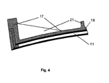
- Fig. 4
- Metallische oder keramische Grundstruktur (11) mit Kühlkanälen und Zuführungsöffnungen und einer außen und stirnseitig aufgebrachten Nickelschicht (17), deren Endkontur mit Rippen und Stege (21) anschließend durch mechanische Bearbeitung erzeugt wird. Zusätzlich bewirkt die NVD-Beschichtung bei porösen Grundstrukturen eine Abdichtung (18) gegen Gase und Flüssigkeiten.
- Fig.5
- Grundkörper, Tragschicht und Verteilungsring als Integrales Bauteil (19) mittels NVD-Beschichtung hergestellt unter Verwendung geeigneter Kernmaterialien (22) zur Gestaltung und Herstellung der Hohlräume und anschließender mechanischer Bearbeitung der Außenkontur (20).
- Fig. 6
- Spalt- und kraftfreie, formschlüssige Verbindung von Grundkörpern (24) aus verschiedenen Materialien mit einer Nickelschicht (23) zur Herstellung von Tragstrukturen und /oder Basismaterial für die Gestaltung von Verbindungen und Anschlussgeometrien oder die Herstellung integraler Gelenkverbindungen.
- Gemäß der Erfindung kann das NVD-Verfahren für folgende Anwendungszwecke eingesetzt werden: (1) Herstellung von Tragstrukturen auf verschiedenen metallischen Bauteilen, (2) Herstellung von Brennkammer-Grundkörpern mit Kühlkanälen aus NVD-Nickel, (3) Herstellung von Brennkammer-Tragstrukturen und den erforderlichen Zu- und Abströmverteilern als integrales Bauteil für Raketenantriebe und Gasgeneratoren, (4) Herstellung von Tragstrukturen auf keramischen Bauteilen, (5) Beschichtung keramischer Bauteile zur Oberflächenabdichtung, (6) Herstellung von Verbindungselementen auf metallischen und keramischen Grundstrukturen, (7) Mechanische Verbindung von Grundkörpern mit einem Nickelmantel und (8) NVD-Abscheidung in Kombination mit einer Lötverbindung.
- Bei den genannten Anwendungen werden die Vorteile der hohen Abscheidungsrate, der oberflächentreuen Auftragung gleichmäßig dicker Nickelschichten auf beliebig geformten Körpern und das Abtragen in offenen Hohlräumen des NVD-Verfahrens genutzt.
- Zunächst wird die Herstellung von Tragstrukturen auf verschiedenen metallischen und nichtmetallischen Bauteilen gemäß dem erfinderischen Verfahren beschrieben.
- Der zu beschichtende Grundkörper wird in bekannter Weise in der NVD-Kammer positioniert und vorbereitet. Mit Hilfe des NVD-Verfahrens wird dann eine bestimmte Nickelschicht aufgetragen, die als Tragstruktur verwendet wird. Die Verbindung des Grundkörpers mit der Nickelschicht wird dann als Bauteil weiterbearbeitet.
- In der Raketentechnik soll die NVD-Beschichtung beim Erzeugen thermisch und strukturmechanisch sehr hoch belasteter metallischer und nichtmetallischer Kühlkörper verwendet werden. Dies wären Brennkammern, Expansionsdüsen und gekühlte Gasgeneratoren. Der zu beschichtende Körper besteht dabei aus einer (gefrästen) mit Kühlkanälen versehenen metallischen Grundstruktur (Fig.1; 10) oder einer keramischen Faserverbund-Struktur (Fig.4; 11) oder aus einem Verbund röhrchenförmiger Einzelelemente (Fig.3; 12a und12b).
- Die Beschichtung kann dann auf verschiedene Arten durchgeführt werden. (Fig.1 und 2)
- A) Beschichtungsseitig offene Kühlkanäle (25):
- a) Die Kühlkanäle werden mit einem geeigneten Material (13) ganz oder teilweise gefüllt und dann im NVD-Verfahren beschichtet (14).
- b) Die Kühlkanäle werden vor der Beschichtung mit einem anderen Verfahren z.B. Galvanik abgedeckt (15) und dann im NVD-Verfahren beschichtet.
- c) Die Kühlkanäle werden an der zu beschichtenden Oberfläche mechanisch oder chemisch so bearbeitet (16a, 16b, 16c), dass eine konturierte Geometrie oder formschlussartige Mikrostrukturen entstehen, die eine NVD-Hohlraumabscheidung ermöglichen und damit eine formschlüssige Verbindung zwischen Tragstruktur und Grundstruktur gegeben ist. Die Kühlkanalabdeckung vor der Beschichtung erfolgt mit einem geeigneten Füllmaterial (13).
- d) Aufbau mit molekularer Anbindung der NVD-Schicht an die Grundstruktur mittels geeigneter chemischer oder galvanotechnischer Vorbehandlung der zu beschichtenden Oberflächen.
- Bei den Beschichtungsarten A)a) und A)b) ist eine molekulare Verbindung mit dem Grundkörper wünschenswert, aber nicht unbedingt erforderlich.
- B) Beschichtungsseitig geschlossene Kühlkanäle (15):
- a) Aufbau mit molekularer Anbindung der NVD-Schicht an die Grundstruktur mittels geeigneter chemischer oder galvanotechnischer Vorbehandlung der zu beschichtenden Oberflächen.
- b) Aufbau ohne Anbindung der NVD-Schicht an die Grundstruktur zur Vermeidung thermischer Zwangskräfte bei Einwirkung unterschiedlicher Temperaturen. Werkstoff- oder anwendungsbedingt ist auch eine mehr oder minder dicke Trennschicht mittels geeigneter Vorbehandlung der zu beschichtenden Oberflächen denkbar.
- c) Die zu beschichtenden Oberflächen werden mechanisch oder chemisch so bearbeitet, dass eine Geometrie entsteht, die eine NVD-Hohlraumabscheidung ermöglicht und somit eine formschlüssige Verbindung zwischen Tragstruktur und Grundstruktur erreicht wird.
- d) Die zu beschichtenden Oberflächen sind werkstoff- oder herstellungsbedingt so porös, dass eine NVD-Hohlraumabscheidung möglich wird und somit eine formschlüssige Verbindung zwischen Tragstruktur und Grundstruktur gegeben ist.
- Als nächstes wird die Herstellung von Brennkammer-Grundkörpern aus NVD-Nickel mit integrierten Kühlkanälen gemäß dem erfinderischen Verfahren beschrieben. (Fig. 5)
- Für bestimmte Triebwerkstypen oder bei Verwendung bestimmter Treibstoffe ist ein Brennkammer-Grundkörper aus 100% Nickel von Vorteil. Das NVD-Verfahren eignet sich sowohl für die Herstellung einer mit Rippen versehenen Grundstruktur (Liner) als auch für die Herstellung eines mit Kühlkanälen versehenen integralen Gesamtkörpers.
- a) Grundstruktur (Liner)
Herstellung der berippten Grundstruktur durch Abscheidung des NVD-Nickels auf einer entsprechend gestalteten Negativform. Wandstärken und Fertigkontur der berippten Grundstruktur können anschließend durch Bearbeitung angepasst und optimiert werden. - b) Integraler Grundkörper mit Tragstruktur
Die kühlmittelführenden Hohlräume (22) werden aus geeigneten Werkstoffen als verlorene Kerne nachgebildet und anschließend mit NVD-Nickel (19) beschichtet. Wandstärken und Fertigkontur (20) des Grundkörpers können anschließend durch Bearbeitung angepasst und optimiert werden. Die Hohlräume entstehen dadurch, dass das Kernmaterial nach dem Beschichtungsvorgang mit geeigneten Hilfsmitteln herausgelöst wird. - Als nächstes wird die Herstellung von Tragstrukturen auf keramischen Bauteilen gemäß dem erfinderischen Verfahren beschrieben. (Fig.4)
- Ähnlich der Beschichtung von metallischen Werkstoffen bietet das NVD-Verfahren die Möglichkeit der Abscheidung auf keramischen Oberflächen (11). Das abgeschiedene Nickel dringt dabei in die poröse Oberfläche (18) ein, verankert sich und bildet bei fortgesetzter Beschichtung die Basis für den strukturellen Aufbau (17).
- Als nächstes wird die Beschichtung keramischer Bauteile zur Oberflächenabdichtung gemäß dem erfinderischen Verfahren beschrieben. (Fig. 4)
- Das im NVD-Verfahren abgeschiedene Nickel füllt die bei keramischen Bauteilen aus dem Prozess gegebenen Poren aus. Dadurch erfolgt auf der Oberfläche (18) eine Abdichtung gegenüber Gasen oder Flüssigkeiten. Bei thermisch hoch belasteten Bauteilen ist dabei die hohe Duktilität des NVD-Nickels von Vorteil.
- Als nächstes wird die Herstellung von Verbindungselementen auf metallischen und keramischen Grundstrukturen gemäß dem erfinderischen Verfahren beschrieben. (Fig. 5 und 6)
- Im NVD-Verfahren können derzeit Nickel-Schichtdicken von über 35mm aufgebracht werden. Die hohen Schichtdicken bieten die Möglichkeit an den beschichteten Bauteilen direkt Verbindungselemente wie Flansche (19), Zu- und Abströmverteiler (20) und Verstärkungsringe (21) mit aufzubauen oder durch nachträgliche mechanische Bearbeitung der NVD-Schicht zu erzeugen.
- Als nächstes wird die mechanische Verbindung von Grundkörpern mit einem Nickelmantel gemäß dem erfinderischen Verfahren beschrieben. (Fig. 6)
- Das oben beschriebene Verfahren zur Verbindung von Kühlkanalsegmenten mit einem Nickelmantel kann generell genutzt werden. Dies ist von besonderem Interesse, wenn Nickelbeschläge (23) mit Materialien unterschiedlicher Eigenschaften (24) und komplexer Geometrie spaltfrei verbunden werden sollen. Beispiele wären Nickel-Verbundbauweisen mit folgenden Materialien: Keramik, Faserverbund-Werkstoffe, Metalle.
- Als nächstes wird die NVD-Abscheidung in Kombination mit einer Lötverbindung gemäß dem erfinderischen Verfahren beschrieben. (Fig. 1 und 2)
- Der Grundkörper wird im Bereich der Bindezone zum NVD-Nickel oder einem Teilbereich davon galvanisch mit einem geeigneten Lot beschichtet. Alternativ kann das Lotmaterial auch in Folienform auf den Grundkörper aufgebracht werden. Danach erfolgt die NVD-Beschichtung. Anschließend wird der Lötprozess in einem Lötofen durchgeführt. Das beschriebene Verfahren hat den Vorteil, dass speziell bei großen zu verbindenden Bauteilen ein genauer Formschluss gegeben ist. Auch bei komplexer und hinterschnittene Formgebung der Bindezone sowie bei Toleranzschwankungen aus dem Fertigungsprozess der Einzelteile gewährleistet dieses Verfahren einen gleichförmigen Lötspalt.
- Bei Brennkammern könnte auf diese Weise der Grundkörper (10) an der Bindefläche (25) zum Nickelmantel mit Lot überzogen werden. Anschließend werden die Kühlkanäle gefräst und mit geeignetem Material gefüllt (13), bevor die spaltfreie Auftragung des Nickelmantels (14) mittels NVD-Beschichtung erfolgt. Nach dem Beschichtungsvorgang wird der Lötprozess zwischen Grundkörper und NVD-Schicht durchgeführt.
Claims (3)
- Verfahren zur Herstellung von Bauteilen für den Raketenbau umfassend die Schritte
Abscheidung von Nickel im NVD-Verfahren auf einen Grundkörper und
Weiterbearbeitung der Verbindung des Grundkörpers mit der Nickelschicht als Bauteil. - Verfahren nach Anspruch 1 ferner umfassend den Schritt
Abdichtung von porösen keramischen und nichtkeramischen Faserverbundstrukturen gegen Gase und Flüssigkeiten. - Verfahren nach Anspruch 2 ferner umfassend den Schritt
Herstellung von gekühlten und nichtgekühlten Grundkörpern aus Nickel für Raketenantriebe.
Applications Claiming Priority (1)
| Application Number | Priority Date | Filing Date | Title |
|---|---|---|---|
| DE200610021539 DE102006021539A1 (de) | 2006-05-08 | 2006-05-08 | Verfahren zur Herstellung von Bauteilen für den Raketenbau |
Publications (2)
| Publication Number | Publication Date |
|---|---|
| EP1854905A1 true EP1854905A1 (de) | 2007-11-14 |
| EP1854905B1 EP1854905B1 (de) | 2012-10-17 |
Family
ID=38213587
Family Applications (1)
| Application Number | Title | Priority Date | Filing Date |
|---|---|---|---|
| EP20070008991 Not-in-force EP1854905B1 (de) | 2006-05-08 | 2007-05-04 | Verfahren zur Herstellung von Bauteilen für den Raketenbau |
Country Status (5)
| Country | Link |
|---|---|
| US (1) | US20070259192A1 (de) |
| EP (1) | EP1854905B1 (de) |
| JP (2) | JP4874865B2 (de) |
| CA (1) | CA2586718C (de) |
| DE (1) | DE102006021539A1 (de) |
Families Citing this family (4)
| Publication number | Priority date | Publication date | Assignee | Title |
|---|---|---|---|---|
| DE102008020198B8 (de) * | 2008-04-15 | 2015-05-13 | Astrium Gmbh | Düsenerweiterung für ein Triebwerk und Verfahren zur Herstellung und Kühlung einer Düsenerweiterung |
| DE102010007272B4 (de) * | 2010-02-08 | 2016-09-15 | Astrium Gmbh | Verfahren zur Herstellung einer regenerativ gekühlten Düsenerweiterung einer Raketenbrennkammer und Düsenerweiterung |
| DE102017129321B4 (de) * | 2017-12-08 | 2024-11-07 | Deutsches Zentrum für Luft- und Raumfahrt e.V. | Brennkammervorrichtung, Fahrzeug |
| CN114932642B (zh) * | 2022-05-24 | 2024-08-23 | 哈尔滨玻璃钢研究院有限公司 | 一种火箭发动机燃烧室壳体封头模压模具及其使用方法 |
Citations (5)
| Publication number | Priority date | Publication date | Assignee | Title |
|---|---|---|---|---|
| US4759950A (en) * | 1986-09-26 | 1988-07-26 | Advance Technology Materials, Inc. | Method for metallizing filaments |
| US5008160A (en) * | 1988-07-11 | 1991-04-16 | Jenkin William C | Method of securing adherent coatings by CVD from metal carbonyls, and articles thus obtained |
| US5470651A (en) * | 1992-08-21 | 1995-11-28 | Mirotech, Inc. | Mandrel for use in nickel vapor deposition processes and nickel molds made thereform |
| US6132518A (en) * | 1998-11-04 | 2000-10-17 | Chemical Vapour Deposition Systems, Inc. | Nickel carbonyl vapour deposition apparatus and method |
| US6838191B1 (en) * | 2003-05-20 | 2005-01-04 | The United States Of America As Represented By The Admistrator Of The National Aeronautics And Space Administration | Blanch resistant and thermal barrier NiAl coating systems for advanced copper alloys |
Family Cites Families (19)
| Publication number | Priority date | Publication date | Assignee | Title |
|---|---|---|---|---|
| BE552004A (de) * | 1952-10-24 | |||
| DE1941296B2 (de) * | 1969-08-14 | 1971-09-30 | Messerschmitt Bolkow Blohm GmbH, 8000 München | Durch ein fluessiges medium regenerativ gekuehlte brenn kammer mit schubduese |
| US4031274A (en) * | 1975-10-14 | 1977-06-21 | General Electric Company | Method for coating cavities with metal |
| JPH0713500B2 (ja) * | 1984-08-29 | 1995-02-15 | 三菱重工業株式会社 | ロケツトエンジン燃焼室製造方法 |
| JPH03241826A (ja) * | 1990-02-20 | 1991-10-29 | Mitsubishi Materials Corp | 半導体素子の製造方法およびこれに用いられる半導体基板 |
| FR2669966B1 (fr) * | 1990-11-30 | 1993-03-26 | Europ Propulsion | Procede de fabrication de paroi de chambre de combustion, notamment pour moteur-fusee, et chambre de combustion obtenue par ce procede. |
| JP3152861B2 (ja) * | 1995-03-31 | 2001-04-03 | 京セラ株式会社 | ダイヤモンド複合部材およびその製造方法 |
| JP3382786B2 (ja) * | 1996-08-13 | 2003-03-04 | 三菱重工業株式会社 | ロケットエンジン |
| US5951791A (en) * | 1997-12-01 | 1999-09-14 | Inco Limited | Method of preparing porous nickel-aluminum structures |
| AU1015999A (en) * | 1998-11-03 | 2000-05-22 | Chemical Vapour Deposition Systems Inc. | Nickel carbonyl vapour deposition apparatus and process |
| FR2785664B1 (fr) * | 1998-11-05 | 2001-02-02 | Snecma | Echangeur de chaleur en materiau composite et procede pour sa fabrication |
| RU2158840C2 (ru) * | 1999-01-21 | 2000-11-10 | Открытое акционерное общество "НПО Энергомаш им. акад. В.П. Глушко" | Корпус камеры жидкостного ракетного двигателя |
| US6463992B1 (en) * | 2000-03-22 | 2002-10-15 | Pratt & Whitney Canada Corp. | Method of manufacturing seamless self-supporting aerodynamically contoured sheet metal aircraft engine parts using nickel vapor deposition |
| NO20002377A (no) * | 2000-05-05 | 2001-06-25 | Nammo Raufoss As | Anordning ved beholder som omslutter et brennbart materiale |
| JP4095764B2 (ja) * | 2000-09-13 | 2008-06-04 | 三菱重工業株式会社 | 成膜装置用金属材料部材及びそれを用いた成膜装置 |
| DE10126926B4 (de) * | 2001-06-01 | 2015-02-19 | Astrium Gmbh | Brennkammer mit Innenmantel aus einem keramischen Komposit-Material und Verfahren zur Herstellung |
| JP2003136628A (ja) * | 2001-11-01 | 2003-05-14 | Toray Ind Inc | 金属酸化物積層フイルム、金属酸化物積層体およびこれらの製造方法 |
| JP2003163260A (ja) * | 2001-11-28 | 2003-06-06 | Canon Inc | 静電吸着装置およびそれを用いた移動テーブル試料台 |
| US6495207B1 (en) * | 2001-12-21 | 2002-12-17 | Pratt & Whitney Canada Corp. | Method of manufacturing a composite wall |
-
2006
- 2006-05-08 DE DE200610021539 patent/DE102006021539A1/de not_active Withdrawn
-
2007
- 2007-04-30 CA CA 2586718 patent/CA2586718C/en not_active Expired - Fee Related
- 2007-05-04 EP EP20070008991 patent/EP1854905B1/de not_active Not-in-force
- 2007-05-07 US US11/745,154 patent/US20070259192A1/en not_active Abandoned
- 2007-05-07 JP JP2007122819A patent/JP4874865B2/ja not_active Expired - Fee Related
-
2011
- 2011-07-01 JP JP2011147246A patent/JP2011185280A/ja active Pending
Patent Citations (5)
| Publication number | Priority date | Publication date | Assignee | Title |
|---|---|---|---|---|
| US4759950A (en) * | 1986-09-26 | 1988-07-26 | Advance Technology Materials, Inc. | Method for metallizing filaments |
| US5008160A (en) * | 1988-07-11 | 1991-04-16 | Jenkin William C | Method of securing adherent coatings by CVD from metal carbonyls, and articles thus obtained |
| US5470651A (en) * | 1992-08-21 | 1995-11-28 | Mirotech, Inc. | Mandrel for use in nickel vapor deposition processes and nickel molds made thereform |
| US6132518A (en) * | 1998-11-04 | 2000-10-17 | Chemical Vapour Deposition Systems, Inc. | Nickel carbonyl vapour deposition apparatus and method |
| US6838191B1 (en) * | 2003-05-20 | 2005-01-04 | The United States Of America As Represented By The Admistrator Of The National Aeronautics And Space Administration | Blanch resistant and thermal barrier NiAl coating systems for advanced copper alloys |
Also Published As
| Publication number | Publication date |
|---|---|
| US20070259192A1 (en) | 2007-11-08 |
| EP1854905B1 (de) | 2012-10-17 |
| JP4874865B2 (ja) | 2012-02-15 |
| CA2586718C (en) | 2015-04-14 |
| JP2011185280A (ja) | 2011-09-22 |
| DE102006021539A1 (de) | 2007-11-15 |
| JP2007303464A (ja) | 2007-11-22 |
| CA2586718A1 (en) | 2007-11-08 |
Similar Documents
| Publication | Publication Date | Title |
|---|---|---|
| EP3468740B1 (de) | Verfahren zum fügen von werkstoffen durch verwendung einer mit einem additiven verfahren hergestellten gitterstruktur | |
| DE102011081112A1 (de) | Verfahren zur Herstellung eines Bauteils für hohe thermische Belastungen, ein Bauteil herstellbar mit dem Verfahren und ein Flugzeugtriebwerk mit dem Bauteil | |
| DE19915082C1 (de) | Verfahren zur Herstellung einer gekühlten Düse für ein Raketentriebwerk | |
| EP2993249A1 (de) | Oberflächenglättung von generativ hergestellten bauteilen und entsprechend hergestellte bauteile einer strömungsmaschine | |
| EP1854905B1 (de) | Verfahren zur Herstellung von Bauteilen für den Raketenbau | |
| US6134785A (en) | Method of fabricating an article of manufacture such as a heat exchanger | |
| DE102018124938B4 (de) | Verfahren zum Bilden einer Wärmedämmung | |
| DE102017130824B4 (de) | Verfahren zum abscheiden einer oder mehrerer schichten von mikrokugeln zum bilden einer wärmedämmschicht | |
| EP3455014A1 (de) | Vorrichtung mit schleuse für die additive herstellung | |
| EP2826959A2 (de) | Verfahren zum Herstellen eines Isolationselements und Isolationselement für ein Gehäuse eines Flugtriebwerks | |
| EP0239571B1 (de) | Mehrschichtiger hohlkörper, verfahren zu seiner herstellung und seine verwendung | |
| DE10126926A1 (de) | Brennkammer mit Innenmantel aus einem keramischen Komposit-Material und Verfahren zur Herstellung | |
| DE102009037893A1 (de) | Herstellung von Hohlkörpern oder Schichten mit Hohlräumen | |
| WO2001079669A1 (de) | Gehäuse mit passivierungsschicht und verfahren zur herstellung eines katalysator-trägerkörpers mit einem solchen gehäuse | |
| DE4321393C2 (de) | Wandstruktur, insbesondere für ein Staustrahltriebwerk | |
| DE102018133001A1 (de) | Thermodämmschicht mit temperaturfolgender schicht | |
| DE102018132997A1 (de) | Spaltfüllung dichtungsschicht von wärmedämmschicht | |
| DE3320557A1 (de) | Verfahren zur herstellung einer raketenbrennkammer und raketenbrennkammer | |
| DE10034508A1 (de) | Verfahren zur Herstellung eines endkonturnahen Formgebungswerkzeug und danach hergestelltes Formgebungswerkzeug | |
| DE102010055791A1 (de) | Verfahren zur Fertigung von Bauteilen aus Refraktärmetallen | |
| DE4139421A1 (de) | Verfahren zum ueberziehen einer substratoberflaeche mit einer sinterschicht und pulverfoermiges ausgangsmaterial dafuer | |
| EP2093409A2 (de) | Düsenerweiterung und Verfahren zur Herstellung einer Düsenerweiterung | |
| DE10219502B4 (de) | Verfahren zum Herstellen gelöteter Wärmetauscherstrukturen, insbesondere regenerativ gekühlter Brennkammern | |
| DE10239416A1 (de) | Verbundkörper aus Keramikschichten und Verfahren zu dessen Herstellung | |
| DE102021116316A1 (de) | Verfahren und system zur fertigung von ausrüstung |
Legal Events
| Date | Code | Title | Description |
|---|---|---|---|
| PUAI | Public reference made under article 153(3) epc to a published international application that has entered the european phase |
Free format text: ORIGINAL CODE: 0009012 |
|
| AK | Designated contracting states |
Kind code of ref document: A1 Designated state(s): AT BE BG CH CY CZ DE DK EE ES FI FR GB GR HU IE IS IT LI LT LU LV MC MT NL PL PT RO SE SI SK TR |
|
| AX | Request for extension of the european patent |
Extension state: AL BA HR MK YU |
|
| 17P | Request for examination filed |
Effective date: 20080317 |
|
| 17Q | First examination report despatched |
Effective date: 20080421 |
|
| AKX | Designation fees paid |
Designated state(s): AT BE BG CH CY CZ DE DK EE ES FI FR GB GR HU IE IS IT LI LT LU LV MC MT NL PL PT RO SE SI SK TR |
|
| GRAP | Despatch of communication of intention to grant a patent |
Free format text: ORIGINAL CODE: EPIDOSNIGR1 |
|
| GRAS | Grant fee paid |
Free format text: ORIGINAL CODE: EPIDOSNIGR3 |
|
| GRAA | (expected) grant |
Free format text: ORIGINAL CODE: 0009210 |
|
| GRAL | Information related to payment of fee for publishing/printing deleted |
Free format text: ORIGINAL CODE: EPIDOSDIGR3 |
|
| GRAS | Grant fee paid |
Free format text: ORIGINAL CODE: EPIDOSNIGR3 |
|
| AK | Designated contracting states |
Kind code of ref document: B1 Designated state(s): AT BE BG CH CY CZ DE DK EE ES FI FR GB GR HU IE IS IT LI LT LU LV MC MT NL PL PT RO SE SI SK TR |
|
| REG | Reference to a national code |
Ref country code: GB Ref legal event code: FG4D Free format text: NOT ENGLISH Ref country code: DE Ref legal event code: R081 Ref document number: 502007010697 Country of ref document: DE Owner name: ARIANEGROUP GMBH, DE Free format text: FORMER OWNER: ASTRIUM GMBH, 81667 MUENCHEN, DE |
|
| REG | Reference to a national code |
Ref country code: CH Ref legal event code: EP |
|
| REG | Reference to a national code |
Ref country code: IE Ref legal event code: FG4D Free format text: LANGUAGE OF EP DOCUMENT: GERMAN |
|
| REG | Reference to a national code |
Ref country code: AT Ref legal event code: REF Ref document number: 579965 Country of ref document: AT Kind code of ref document: T Effective date: 20121115 |
|
| REG | Reference to a national code |
Ref country code: DE Ref legal event code: R096 Ref document number: 502007010697 Country of ref document: DE Effective date: 20121220 |
|
| REG | Reference to a national code |
Ref country code: NL Ref legal event code: VDEP Effective date: 20121017 |
|
| REG | Reference to a national code |
Ref country code: LT Ref legal event code: MG4D |
|
| PG25 | Lapsed in a contracting state [announced via postgrant information from national office to epo] |
Ref country code: FI Free format text: LAPSE BECAUSE OF FAILURE TO SUBMIT A TRANSLATION OF THE DESCRIPTION OR TO PAY THE FEE WITHIN THE PRESCRIBED TIME-LIMIT Effective date: 20121017 Ref country code: LT Free format text: LAPSE BECAUSE OF FAILURE TO SUBMIT A TRANSLATION OF THE DESCRIPTION OR TO PAY THE FEE WITHIN THE PRESCRIBED TIME-LIMIT Effective date: 20121017 Ref country code: IS Free format text: LAPSE BECAUSE OF FAILURE TO SUBMIT A TRANSLATION OF THE DESCRIPTION OR TO PAY THE FEE WITHIN THE PRESCRIBED TIME-LIMIT Effective date: 20130217 Ref country code: ES Free format text: LAPSE BECAUSE OF FAILURE TO SUBMIT A TRANSLATION OF THE DESCRIPTION OR TO PAY THE FEE WITHIN THE PRESCRIBED TIME-LIMIT Effective date: 20130128 Ref country code: SE Free format text: LAPSE BECAUSE OF FAILURE TO SUBMIT A TRANSLATION OF THE DESCRIPTION OR TO PAY THE FEE WITHIN THE PRESCRIBED TIME-LIMIT Effective date: 20121017 Ref country code: NL Free format text: LAPSE BECAUSE OF FAILURE TO SUBMIT A TRANSLATION OF THE DESCRIPTION OR TO PAY THE FEE WITHIN THE PRESCRIBED TIME-LIMIT Effective date: 20121017 |
|
| PG25 | Lapsed in a contracting state [announced via postgrant information from national office to epo] |
Ref country code: PL Free format text: LAPSE BECAUSE OF FAILURE TO SUBMIT A TRANSLATION OF THE DESCRIPTION OR TO PAY THE FEE WITHIN THE PRESCRIBED TIME-LIMIT Effective date: 20121017 Ref country code: SI Free format text: LAPSE BECAUSE OF FAILURE TO SUBMIT A TRANSLATION OF THE DESCRIPTION OR TO PAY THE FEE WITHIN THE PRESCRIBED TIME-LIMIT Effective date: 20121017 Ref country code: GR Free format text: LAPSE BECAUSE OF FAILURE TO SUBMIT A TRANSLATION OF THE DESCRIPTION OR TO PAY THE FEE WITHIN THE PRESCRIBED TIME-LIMIT Effective date: 20130118 Ref country code: LV Free format text: LAPSE BECAUSE OF FAILURE TO SUBMIT A TRANSLATION OF THE DESCRIPTION OR TO PAY THE FEE WITHIN THE PRESCRIBED TIME-LIMIT Effective date: 20121017 Ref country code: PT Free format text: LAPSE BECAUSE OF FAILURE TO SUBMIT A TRANSLATION OF THE DESCRIPTION OR TO PAY THE FEE WITHIN THE PRESCRIBED TIME-LIMIT Effective date: 20130218 Ref country code: CY Free format text: LAPSE BECAUSE OF FAILURE TO SUBMIT A TRANSLATION OF THE DESCRIPTION OR TO PAY THE FEE WITHIN THE PRESCRIBED TIME-LIMIT Effective date: 20121017 |
|
| PG25 | Lapsed in a contracting state [announced via postgrant information from national office to epo] |
Ref country code: EE Free format text: LAPSE BECAUSE OF FAILURE TO SUBMIT A TRANSLATION OF THE DESCRIPTION OR TO PAY THE FEE WITHIN THE PRESCRIBED TIME-LIMIT Effective date: 20121017 Ref country code: DK Free format text: LAPSE BECAUSE OF FAILURE TO SUBMIT A TRANSLATION OF THE DESCRIPTION OR TO PAY THE FEE WITHIN THE PRESCRIBED TIME-LIMIT Effective date: 20121017 Ref country code: SK Free format text: LAPSE BECAUSE OF FAILURE TO SUBMIT A TRANSLATION OF THE DESCRIPTION OR TO PAY THE FEE WITHIN THE PRESCRIBED TIME-LIMIT Effective date: 20121017 Ref country code: BG Free format text: LAPSE BECAUSE OF FAILURE TO SUBMIT A TRANSLATION OF THE DESCRIPTION OR TO PAY THE FEE WITHIN THE PRESCRIBED TIME-LIMIT Effective date: 20130117 Ref country code: CZ Free format text: LAPSE BECAUSE OF FAILURE TO SUBMIT A TRANSLATION OF THE DESCRIPTION OR TO PAY THE FEE WITHIN THE PRESCRIBED TIME-LIMIT Effective date: 20121017 |
|
| PLBE | No opposition filed within time limit |
Free format text: ORIGINAL CODE: 0009261 |
|
| STAA | Information on the status of an ep patent application or granted ep patent |
Free format text: STATUS: NO OPPOSITION FILED WITHIN TIME LIMIT |
|
| PG25 | Lapsed in a contracting state [announced via postgrant information from national office to epo] |
Ref country code: IT Free format text: LAPSE BECAUSE OF FAILURE TO SUBMIT A TRANSLATION OF THE DESCRIPTION OR TO PAY THE FEE WITHIN THE PRESCRIBED TIME-LIMIT Effective date: 20121017 Ref country code: RO Free format text: LAPSE BECAUSE OF FAILURE TO SUBMIT A TRANSLATION OF THE DESCRIPTION OR TO PAY THE FEE WITHIN THE PRESCRIBED TIME-LIMIT Effective date: 20121017 |
|
| 26N | No opposition filed |
Effective date: 20130718 |
|
| REG | Reference to a national code |
Ref country code: DE Ref legal event code: R097 Ref document number: 502007010697 Country of ref document: DE Effective date: 20130718 |
|
| BERE | Be: lapsed |
Owner name: ASTRIUM G.M.B.H. Effective date: 20130531 |
|
| PG25 | Lapsed in a contracting state [announced via postgrant information from national office to epo] |
Ref country code: MC Free format text: LAPSE BECAUSE OF FAILURE TO SUBMIT A TRANSLATION OF THE DESCRIPTION OR TO PAY THE FEE WITHIN THE PRESCRIBED TIME-LIMIT Effective date: 20121017 |
|
| REG | Reference to a national code |
Ref country code: CH Ref legal event code: PL |
|
| GBPC | Gb: european patent ceased through non-payment of renewal fee |
Effective date: 20130504 |
|
| PG25 | Lapsed in a contracting state [announced via postgrant information from national office to epo] |
Ref country code: LI Free format text: LAPSE BECAUSE OF NON-PAYMENT OF DUE FEES Effective date: 20130531 Ref country code: CH Free format text: LAPSE BECAUSE OF NON-PAYMENT OF DUE FEES Effective date: 20130531 |
|
| REG | Reference to a national code |
Ref country code: IE Ref legal event code: MM4A |
|
| PG25 | Lapsed in a contracting state [announced via postgrant information from national office to epo] |
Ref country code: BE Free format text: LAPSE BECAUSE OF NON-PAYMENT OF DUE FEES Effective date: 20130531 |
|
| REG | Reference to a national code |
Ref country code: FR Ref legal event code: ST Effective date: 20140131 |
|
| PG25 | Lapsed in a contracting state [announced via postgrant information from national office to epo] |
Ref country code: GB Free format text: LAPSE BECAUSE OF NON-PAYMENT OF DUE FEES Effective date: 20130504 Ref country code: IE Free format text: LAPSE BECAUSE OF NON-PAYMENT OF DUE FEES Effective date: 20130504 |
|
| PG25 | Lapsed in a contracting state [announced via postgrant information from national office to epo] |
Ref country code: FR Free format text: LAPSE BECAUSE OF NON-PAYMENT OF DUE FEES Effective date: 20130531 |
|
| REG | Reference to a national code |
Ref country code: AT Ref legal event code: MM01 Ref document number: 579965 Country of ref document: AT Kind code of ref document: T Effective date: 20130504 |
|
| PG25 | Lapsed in a contracting state [announced via postgrant information from national office to epo] |
Ref country code: AT Free format text: LAPSE BECAUSE OF NON-PAYMENT OF DUE FEES Effective date: 20130504 |
|
| PG25 | Lapsed in a contracting state [announced via postgrant information from national office to epo] |
Ref country code: MT Free format text: LAPSE BECAUSE OF FAILURE TO SUBMIT A TRANSLATION OF THE DESCRIPTION OR TO PAY THE FEE WITHIN THE PRESCRIBED TIME-LIMIT Effective date: 20121017 |
|
| PG25 | Lapsed in a contracting state [announced via postgrant information from national office to epo] |
Ref country code: TR Free format text: LAPSE BECAUSE OF FAILURE TO SUBMIT A TRANSLATION OF THE DESCRIPTION OR TO PAY THE FEE WITHIN THE PRESCRIBED TIME-LIMIT Effective date: 20121017 |
|
| PG25 | Lapsed in a contracting state [announced via postgrant information from national office to epo] |
Ref country code: LU Free format text: LAPSE BECAUSE OF NON-PAYMENT OF DUE FEES Effective date: 20130504 Ref country code: HU Free format text: LAPSE BECAUSE OF FAILURE TO SUBMIT A TRANSLATION OF THE DESCRIPTION OR TO PAY THE FEE WITHIN THE PRESCRIBED TIME-LIMIT; INVALID AB INITIO Effective date: 20070504 |
|
| PGFP | Annual fee paid to national office [announced via postgrant information from national office to epo] |
Ref country code: DE Payment date: 20170523 Year of fee payment: 11 |
|
| REG | Reference to a national code |
Ref country code: DE Ref legal event code: R081 Ref document number: 502007010697 Country of ref document: DE Owner name: ARIANEGROUP GMBH, DE Free format text: FORMER OWNER: ASTRIUM GMBH, 81667 MUENCHEN, DE |
|
| REG | Reference to a national code |
Ref country code: DE Ref legal event code: R119 Ref document number: 502007010697 Country of ref document: DE |
|
| PG25 | Lapsed in a contracting state [announced via postgrant information from national office to epo] |
Ref country code: DE Free format text: LAPSE BECAUSE OF NON-PAYMENT OF DUE FEES Effective date: 20181201 |