EP1853391B1 - Spender - Google Patents
Spender Download PDFInfo
- Publication number
- EP1853391B1 EP1853391B1 EP06709946A EP06709946A EP1853391B1 EP 1853391 B1 EP1853391 B1 EP 1853391B1 EP 06709946 A EP06709946 A EP 06709946A EP 06709946 A EP06709946 A EP 06709946A EP 1853391 B1 EP1853391 B1 EP 1853391B1
- Authority
- EP
- European Patent Office
- Prior art keywords
- probe
- duct
- frangible membrane
- sheath
- dispenser according
- Prior art date
- Legal status (The legal status is an assumption and is not a legal conclusion. Google has not performed a legal analysis and makes no representation as to the accuracy of the status listed.)
- Expired - Lifetime
Links
Images


Classifications
-
- B—PERFORMING OPERATIONS; TRANSPORTING
- B05—SPRAYING OR ATOMISING IN GENERAL; APPLYING FLUENT MATERIALS TO SURFACES, IN GENERAL
- B05B—SPRAYING APPARATUS; ATOMISING APPARATUS; NOZZLES
- B05B11/00—Single-unit hand-held apparatus in which flow of contents is produced by the muscular force of the operator at the moment of use
- B05B11/01—Single-unit hand-held apparatus in which flow of contents is produced by the muscular force of the operator at the moment of use characterised by the means producing the flow
- B05B11/06—Gas or vapour producing the flow, e.g. from a compressible bulb or air pump
- B05B11/062—Gas or vapour producing the flow, e.g. from a compressible bulb or air pump designed for spraying particulate material
-
- A—HUMAN NECESSITIES
- A61—MEDICAL OR VETERINARY SCIENCE; HYGIENE
- A61M—DEVICES FOR INTRODUCING MEDIA INTO, OR ONTO, THE BODY; DEVICES FOR TRANSDUCING BODY MEDIA OR FOR TAKING MEDIA FROM THE BODY; DEVICES FOR PRODUCING OR ENDING SLEEP OR STUPOR
- A61M13/00—Insufflators for therapeutic or disinfectant purposes, i.e. devices for blowing a gas, powder or vapour into the body
-
- A—HUMAN NECESSITIES
- A61—MEDICAL OR VETERINARY SCIENCE; HYGIENE
- A61M—DEVICES FOR INTRODUCING MEDIA INTO, OR ONTO, THE BODY; DEVICES FOR TRANSDUCING BODY MEDIA OR FOR TAKING MEDIA FROM THE BODY; DEVICES FOR PRODUCING OR ENDING SLEEP OR STUPOR
- A61M15/00—Inhalators
- A61M15/0028—Inhalators using prepacked dosages, one for each application, e.g. capsules to be perforated or broken-up
-
- A—HUMAN NECESSITIES
- A61—MEDICAL OR VETERINARY SCIENCE; HYGIENE
- A61M—DEVICES FOR INTRODUCING MEDIA INTO, OR ONTO, THE BODY; DEVICES FOR TRANSDUCING BODY MEDIA OR FOR TAKING MEDIA FROM THE BODY; DEVICES FOR PRODUCING OR ENDING SLEEP OR STUPOR
- A61M15/00—Inhalators
- A61M15/0028—Inhalators using prepacked dosages, one for each application, e.g. capsules to be perforated or broken-up
- A61M15/003—Inhalators using prepacked dosages, one for each application, e.g. capsules to be perforated or broken-up using capsules, e.g. to be perforated or broken-up
- A61M15/0033—Details of the piercing or cutting means
- A61M15/0035—Piercing means
- A61M15/0036—Piercing means hollow piercing means
-
- A—HUMAN NECESSITIES
- A61—MEDICAL OR VETERINARY SCIENCE; HYGIENE
- A61M—DEVICES FOR INTRODUCING MEDIA INTO, OR ONTO, THE BODY; DEVICES FOR TRANSDUCING BODY MEDIA OR FOR TAKING MEDIA FROM THE BODY; DEVICES FOR PRODUCING OR ENDING SLEEP OR STUPOR
- A61M2202/00—Special media to be introduced, removed or treated
- A61M2202/06—Solids
- A61M2202/064—Powder
Definitions
- the present invention relates to a dispenser, in particular a dispenser with a frangible membrane which is pierced during use to release a product, such as a medicament.
- EP 1 329 237 discloses such a dispenser according to the preamble of claim 1.
- a dispenser with a frangible membrane is disclosed for example in GB 2,367,756 .
- the frangible membrane keeps the product to be dispensed sealed prior to use to prevent leakage of any of the product and provides protection against contamination or ingress of moisture from the air for example. It is particularly desirable to protect powdered product from moisture because when in contact with moisture, the powder becomes less free flowing and harder to dispense.
- a probe with a piercing tip is provided slidably within a duct.
- a product to be dispensed such as a powdered medicament, is provided in the probe and a sheath with a frangible member is provided over the piercing tip of the probe to seal the product in the probe.
- the probe and sheath are slid along the duct until the sheath engages an annular shoulder preventing its further movement and the piercing tip of the probe pierces the frangible membrane on the sheath and the product is dispensed using compressed air from a bellows.
- the dispenser disclosed in GB 2,367,756 provides good protection for the product to be dispensed using the frangible membrane.
- a hand-held dispenser for dispensing a pharmaceutical product comprising
- the ability to substantially equalise the pressure in the air compression device and the pressure above the frangible membrane provides for a more consistent release of pharmaceutical product when the frangible membrane is pierced. This is because the compressed air from the air compression device which expels the pharmaceutical product through the probe, the piercing tip and the pierced frangible membrane does not encounter a sudden change in pressure as it passes with the entrained pharmaceutical product into the duct through the pierced frangible membrane. A sudden increase or decrease in pressure as the compressed air with entrained pharmaceutical product passes through the pierced frangible membrane would impede the flow of compressed air and pharmaceutical product reducing the amount discharged and providing a less consistent discharge.
- the channel substantially equalises the pressure in the air compression device and the pressure above the frangible membrane on the side of the frangible membrane opposite to that on which the probe is initially provided.
- the probe may be arranged to be slid in the duct.
- the channel is preferably provided as a gap between the inside surface of the duct and the outside surface of the probe or a sheath mounted on the probe.
- the air path through the probe has a lower resistance than the channel which substantially equalises the pressure in the air compression device and the air pressure above the frangible membrane. This ensures that the majority of the compressed air is used to expel the pharmaceutical product.
- the frangible membrane is preferably provide at one end portion of a sheath which has a first larger diameter portion and a second smaller diameter portion defining an external shoulder therebetween to engage with a corresponding internal shoulder on the inside surface of the duct and a spacer is preferably provided on one or both of the shoulders to maintain the channel past the engaged shoulders.
- the spacer may for example be one or more of a recess, a protrusion or a rib or a combination of these.
- One or more spacers which may for example be one or more of a recess protrusion or rib, may be provided on the inside surface of the duct or the outside surface of the sheath to maintain the gap forming the channel therebetween.
- the air compression device may be bellows, a plunger or a pump for example.
- frangible membrane may be mounted to the duct.
- the piercing tip comprises a generally annular cutting edge with an interruption therein.
- the piercing tip is preferably the end portion of a cylindrical probe for housing the product to be dispensed.
- the interruption in the generally annular cutting edge of the piercing tip enables a portion of the frangible membrane to remain attached to the duct or sheath on which it is provided, so that the frangible membrane does not become completely detached from the duct or sheath and interfere with the dispensing of the product.
- the interruption in the generally annular cutting edge enables the frangible membrane to be pierced at the same point every time providing a consistent dispensed product spray pattern so that dispensed product can be directed for example to a particular portion of a nasal cavity.
- the duct may be sealed at a portion nearer to an outlet than where the probe and sheath are provided.
- the seal may be for example, a further frangible membrane which could also be pierced by the piercing tip or a removable cap.
- a first embodiment of the present invention comprises a housing 1 having a generally cylindrical section 5, a tip 6 and finger rests 8.
- the cylindrical section 5 of the housing 1 is provided with an internal, axially orientated, tubular extension 9.
- a bore of the tubular extension 9 is closed off partway along its length by a first frangible membrane 10.
- the bore defines a duct 12 extending from the first frangible membrane 10 in a direction of an open end 18 of the tubular extension 9 and an outlet duct 11 extending from the first frangible membrane 10 in a direction of the tip 6.
- the extremity of the outlet duct 11 distal the first frangible membrane 10 defines an outlet 7 in tip 6.
- the duct 12 and outlet duct 11 preferably both extend along a longitudinal axis 17 of the housing 1.
- the duct 12 has a first bore 13 of larger diameter and a second bore 14 of narrower diameter with an annular internal shoulder 15 provided therebetween.
- the finger rests 8 may be formed by a single annular flange extending from the cylindrical section 5 or by two or more separate flanges circumferentially spaced around the cylindrical sections 5.
- the finger rests 8 have a skirt 8a extending therefrom.
- a bellows unit 2 is joined to the housing 1.
- the bellows unit 2 comprises an annular mounting flange 22 and an axially extending bellows portion 24 having a plurality of concertina formations 20 formed therein.
- An end of the bellows unit 2 distal the mounting flange 22 is closed off by an end face 23 defining a finger or thumb rest.
- a probe 3 is provided within the bellows unit 2 and housing 1.
- the probe 3 comprises a cylindrical extension 32 which is mounted by means of a flange 31 to the inside of end face 23 of the bellows unit 2 so as to lie extending substantially along longitudinal axis 17.
- the cylindrical extension 32 comprises a hollow portion at an end distal the flange 31 defining a powder storage chamber 33.
- the storage chamber 33 is provided with a hemi-spherically shaped lower end 38 which is believed to lead to a more efficient entrainment and removal of the powdered product from the storage chamber 33.
- the lower end may be V-shaped or U-shaped in cross-section.
- the distal end of the cylindrical extension 32 is shaped to form a piercing tip 35 described in more detail later.
- a radially directed aperture 34 is provided in the wall of the cylindrical extension 32 communicating with the storage chamber 33.
- a sheath 4 is slidably mounted on the cylindrical extension 32.
- the sheath 4 comprises a cylindrical portion 41 having a radially orientated aperture 42 therein and a smaller diameter portion 45.
- the sheath 4 is closed at one end by a second frangible membrane 44.
- the junction between the cylindrical portion 41 and the smaller diameter portion 45 defines an external annular shoulder 43.
- the internal diameter of the sheath 4 is such that sliding movement between the sheath 4 and probe 3 is facilitated while maintaining an air-tight seal therebetween.
- Optionally sliding seal members (not shown), such as O-rings, may be provided between the sheath 4 and probe 3 to improve the seal integrity.
- the product to be dispensed in this example a powdered product, is held in the storage chamber 33 .
- the sheath 4 Before use, in a storage condition as shown in Figure 1 , the sheath 4 is mounted on probe 3 with the piercing tip 35 in close proximity to or abutting against the second frangible membrane 44. In this position the radial apertures 34 and 42 are out of alignment and there is consequently no open path between an interior 25 of the bellows portion 24 and the storage chamber 33. Thus, the apertures 34 and 42, which together form an inlet valve, are in a 'closed' position.
- a channel 46 is provided from the volume in the duct 12 above the second frangible membrane 44 on the top of the sheath 4 (on the opposite side of the frangible membrane 44 from the probe 3) to an interior 25 of the bellows 2.
- the channel 46 is provided by the outside diameters of the cylindrical portion 41 of the sheath 4 and the smaller diameter portion 45 of the sheath 4 and the inside diameters of the first 13 and second 14 bores of the duct 12 being selected to provide gaps therebetween. These gaps enable air to be expelled from above the second frangible membrane 44 as the probe 3 and sheath 4 slide through the duct 12 towards the first frangible membrane 10.
- One or more axial spacers are provided on or between the external annular shoulder 43 and the internal shoulder 15 to provide an air passage between the second 14 and the first 13 bores of the duct 12 when the probe 3 and sheath 4 are inserted into the second narrower bore 14 as shown in Figure 2 .
- These one or more spacers may for example, take the form of one or more recesses 47 in the external annular shoulder 43 as shown in Figure 3 , one or more protrusions 48 on the external annular shoulder 43 as shown in Figure 4 , one or more ribs 49 on the external annular shoulder 43 as shown in Figure 5 or any number and combination of recesses, protrusions and ribs.
- one or more spacers such as any number of combination of recesses, protrusions and ribs may be provided on the underside of the annular internal shoulder 15 (not shown).
- Spacers 50, 51, 52 may also be provided at the top of the reduced diameter portion 45 or the underside of the top of the second narrower diameter portion 14 of the duct 12 (not shown) to enhance the channel 46 from above the second frangible member 44.
- These spacers may, for example, take the form of one or more recesses 50 as shown in Figure 3 , one or more protrusions 51 as shown in Figure 4 , one or more ribs 52 as shown in Figure 5 or any number or combination thereof.
- one or more spacers which may for example comprise any number or combination of recesses, protrusions or ribs (not shown) may be provided on the underside of the top of the second narrower diameter portion 14 of the duct 12.
- circumferential spacers may be provided on one or both of the outside surface of the cylindrical portion 41 and the inside surface of the first bore 13 of the duct 12 and/or on one or both of the outside circumference of the smaller diameter portion 45 and the inside surface of the second bore 14 of the duct 12 to ensure the maintenance of the channel forming gap 46 therebetween.
- These circumferential spacers may, for example take the form of one or more recesses, protrusions or ribs.
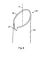
- FIG. 6 shows an enlarged view of the piercing tip 35 at the distal end of the cylindrical extension 32.
- the piercing tip 35 comprises the end of the cylindrical extension 32 which is inclined to the perpendicular or non-orthogonal to the axis 17.
- the cutting edge 36 at the end of the cylindrical portion 32 is substantially annular with an interruption or cut-out 37 therein.
- the non-cutting interruption 37 does not pierce the frangible membranes 10, 44 leaving a portion of the frangible membranes 10, 44 connected to the duct 12 and sheath 4 respectively whilst the dispenser dispenses its contents.
- the non-cutting interruption does not cut the frangible membranes because it is arranged to have sufficient depth such that it does not reach the frangible membranes when the external annular shoulder 43 of the sheath 4 engages the internal annular shoulder 15 of the duct 12.
- the base of the interruption or cut-out portion is preferably blunt to prevent it from cutting a membrane.
- the frangible membranes 10, 44 remain attached to the duct 12 and sheath 4 at predetermined points they do not interfere with the dispensing of the product so a more reliable and reproducible flow pattern is obtained.
- the frangible membranes are not detached, they are not dispensed with the pharmaceutical product into a user's nose or mouth for example.
- the housing 1, probe 3 and sheath 4 are manufactured from polyethylene or polypropylene or similar material.
- the frangible membranes 10, 44 are manufactured from polyethylene or polypropylene or similar material.
- the probe 3 may be manufactured from a metal such as stainless steel.
- the bellows unit 2 is manufactured from polyethylene, polypropylene, a thermoplastic elastomer or other similarly flexible polymer.
- the unit 2 may be formed from a single moulding of a single material. Alternatively, the unit 2 may be formed as a two-part moulding, each part being of a different material.
- the materials of the dispenser lend themselves to easy and ready recycling.
- the absence of any metallic or ceramic components reduces the cost of processing the recycled material.
- the components of the dispenser are moulded. This leads to low levels of material waste.
- the current design allows for a low number of individual parts which reduces assembly time and cost.
- the whole apparatus may be formed from only three components, the first component being the housing 1 including the first frangible membrane 10, the second component being the bellows unit 2 and probe 3 formed as a unitary part, and the third component being the sheath 4 including the second frangible membrane 44.
- a user holds the apparatus typically by means of two or more fingers positioned on the finger rests 8 and a thumb positioned on end face 23.
- the top 6 is then inserted into the nose (or mouth if the apparatus is for pulmonary use or any other orifice for any other use). Inhalation at this stage is ineffective since the first frangible membrane 10 seals off the outlet duct 11.
- the user depresses the end face 23 of the bellows unit 2 so as to move the probe 3 and sheath 4 axially into housing 1 in the direction of tip 6. Initially, the probe 3 and sheath 4 are free to move unhindered with the smaller diameter portion 45 of the sheath 4 being slidingly received in the second narrower portion 14 of the duct 12.
- both of the frangible membranes 44, 10 are ruptured from below with the piercing means 35 moving relative to the membranes in the direction of the tip 6.
- the 'flap' of the membrane which is left connected to the sheath 4 and duct 12 respectively because of the interruption 37 in the generally annular cutting edge of the piercing tip 35 after rupture is positioned above the membrane periphery such that as gas passes the membrane the 'flap' tends to be moved away from the hole formed in the membrane so as not to block the flow path unlike where a membrane is ruptured from above.
- a gap is preferably provided above the frangible membranes 10, 44 in the actuated device to accommodate the flaps provided by the pierced frangible membranes 10, 44.
- the piercing tip 35 passes through the first frangible membrane 10 barbs (not shown) or other snap-fit formations may be engaged and retained with an annular lip of the first frangible membrane 10, preventing retraction of the probe 3 in the direction of the bellows unit 2.
- the barbs prevent any attempt at reuse of the dispensing apparatus and also provide a clear visual indication that the apparatus has been used.
- the axial length of the smaller diameter portion 45 of the sheath 4 and the duct 12 can be chosen such that the first and second frangible membranes lie in close proximity at the point of rupture ensuring that the user feels a single, positive sensory signal that the storage chamber 33 has been opened.
- the air path through the probe has a lower air resistance than the equalising channel 46 to ensure that the majority of compressed air is used to expel the pharmaceutical product.
- the degree of compression and pressurisation of the air within bellows unit 2 provides adequate energy to efficiently entrain and dispense the powdered product with little or no inhalatory effort by the user.
- this means that the apparatus may be used for dispensing products to users who can provide little inhalatory effort such as children or the elderly as well as to users who are unable to provide any inhalatory effort such as those who are unconscious.
- a reproducible spray pattern may be achieved to promote delivery of a medicament to a desired area, for example a predetermined portion of a nasal cavity.
- the channel 46 could be any suitable flow path such as for example a conduit provided in the cylindrical section 5 connecting the top of the second frangible membrane 44 to the interior of the bellows 2 directly.
- the first frangible membrane 10 could be replaced by a removable cap (not shown) or omitted. If used, the first frangible membrane 10 could be pierced by any suitable means such as by a piercing tip (not shown) passed down through outlet 11.
- any suitable air compression device could be used such as, for example a plunger or a pump.
Landscapes
- Health & Medical Sciences (AREA)
- Engineering & Computer Science (AREA)
- General Health & Medical Sciences (AREA)
- Public Health (AREA)
- Heart & Thoracic Surgery (AREA)
- Hematology (AREA)
- Life Sciences & Earth Sciences (AREA)
- Animal Behavior & Ethology (AREA)
- Anesthesiology (AREA)
- Biomedical Technology (AREA)
- Veterinary Medicine (AREA)
- Bioinformatics & Cheminformatics (AREA)
- Pulmonology (AREA)
- Medical Preparation Storing Or Oral Administration Devices (AREA)
- Containers And Packaging Bodies Having A Special Means To Remove Contents (AREA)
- Coating Apparatus (AREA)
- Fats And Perfumes (AREA)
Claims (13)
- In einer Hand haltbare Ausgabevorrichtung zum Ausgeben eines pharmazeutischen Produkts, wobei die Ausgabevorrichtung umfasst:ein einen Durchgang (12) bereitstellendes Gehäuse (1);eine im Durchgang (12) bereitgestellte zerstörbare Membran (44);eine Sonde (3) mit einer im Durchgang angebrachten Durchstechspitze, wobei die Sonde derart angeordnet ist, dass bei Verwendung die Durchstechspitze (35) die zerstörbare Membran (44) durchsticht; undeine Luftkompressionsvorrichtung (2) zum Komprimieren von Luft, um ein pharmazeutisches Produkt durch die Sonde (3) auszustoßen;dadurch gekennzeichnet, dass die Ausgabevorrichtung einen Kanal (46) umfasst, um den Druck in der Luftkompressionsvorrichtung (2) und den Druck über der zerstörbaren Membran (44) im Wesentlichen auszugleichen.
- Ausgabevorrichtung nach Anspruch 1, wobei ein Luftpfad (34) durch die Sonde zum Ausstoßen eines pharmazeutischen Produkts einen geringeren Widerstand als der Kanal (46) aufweist.
- Ausgabevorrichtung nach Anspruch 1 oder Anspruch 2, wobei der Kanal (46) einen Spalt zwischen der Innenfläche des Durchgangs und der Außenfläche der Sonde (3) oder einer auf der Sonde angebrachten Umhüllung (4) umfasst.
- Ausgabevorrichtung nach einem der vorhergehenden Ansprüche, wobei die zerstörbare Membran (44) auf einer Umhüllung (4) bereitgestellt ist, die einen ersten Abschnitt (41) mit größerem Durchmesser und einen zweiten axial beabstandeten Abschnitt (45) mit kleinerem Durchmesser umfasst, wodurch dazwischen eine externe Schulter (43) definiert wird, und die Innenfläche des Durchgangs eine entsprechende interne Schulter (15) aufweist, die in die externe Schulter (43) der Umhüllung eingreifen kann, und ein Axialabstandhalter (47, 48, 49) an der externen oder/und internen Schulter (43; 15) bereitgestellt ist, um den Kanal (46) jenseits der in Eingriff stehenden Schultern (43; 15) aufrecht zu erhalten.
- Ausgabevorrichtung nach Anspruch 4, wobei der Axialabstandhalter eine oder mehrere Vertiefungen (47) umfasst.
- Ausgabevorrichtung nach Anspruch 4 oder Anspruch 5, wobei der Axialabstandhalter einen oder mehrere Vorsprünge (48) umfasst.
- Ausgabevorrichtung nach einem der Ansprüche 4 bis 6, wobei der Axialabstandhalter eine oder mehrere Rippen (49) umfasst.
- Ausgabevorrichtung nach einem der Ansprüche 3 bis 7, wobei ein Umfangsabstandhalter an der Innenfläche des Durchgangs (12) oder/und der Außenfläche der Sonde (3) oder der Umhüllung (4) bereitgestellt ist.
- Ausgabevorrichtung nach Anspruch 8, wobei der Umfangsabstandhalter eines oder mehreres aus einer Vertiefung, einem Vorsprung und/oder einer Rippe umfasst.
- Ausgabevorrichtung nach einem der Ansprüche 3 bis 9, wobei ein Axialabstandhalter am distalen Ende der Sonde (3) oder der Umhüllung (4) bereitgestellt ist.
- Ausgabevorrichtung nach einem der vorhergehenden Ansprüche, wobei die Durchstechspitze (35) eine allgemein ringförmige Schnittkante (36) an einem Endabschnitt der Sonde (3) mit einer Unterbrechung (37) in der allgemein ringförmigen Schnittkante (36) umfasst.
- Ausgabevorrichtung nach Anspruch 11, wobei die allgemein ringförmige Schnittkante (36) in einer Ebene liegt, die nicht orthoganal auf einer Achse der Sonde (3) steht.
- Ausgabevorrichtung nach Anspruch 12, wobei die nicht orthogonale Ebene ein oberes Ende und einer unteres Ende aufweist und die Unterbrechung (37) sich bei dem unteren Ende befindet.
Applications Claiming Priority (2)
| Application Number | Priority Date | Filing Date | Title |
|---|---|---|---|
| GB0504441A GB2422786B (en) | 2005-03-03 | 2005-03-03 | Dispenser |
| PCT/GB2006/000722 WO2006092590A2 (en) | 2005-03-03 | 2006-03-01 | Dispenser with frangible membrane |
Publications (2)
| Publication Number | Publication Date |
|---|---|
| EP1853391A2 EP1853391A2 (de) | 2007-11-14 |
| EP1853391B1 true EP1853391B1 (de) | 2008-10-01 |
Family
ID=34430597
Family Applications (1)
| Application Number | Title | Priority Date | Filing Date |
|---|---|---|---|
| EP06709946A Expired - Lifetime EP1853391B1 (de) | 2005-03-03 | 2006-03-01 | Spender |
Country Status (6)
| Country | Link |
|---|---|
| US (1) | US8056762B2 (de) |
| EP (1) | EP1853391B1 (de) |
| AT (1) | ATE409527T1 (de) |
| DE (1) | DE602006002962D1 (de) |
| GB (1) | GB2422786B (de) |
| WO (1) | WO2006092590A2 (de) |
Families Citing this family (34)
| Publication number | Priority date | Publication date | Assignee | Title |
|---|---|---|---|---|
| GB2422786B (en) | 2005-03-03 | 2007-05-23 | Bespak Plc | Dispenser |
| EP2077132A1 (de) | 2008-01-02 | 2009-07-08 | Boehringer Ingelheim Pharma GmbH & Co. KG | Abgabevorrichtung, Aufbewahrungsvorrichtung und Verfahren zur Abgabe einer Formulierung |
| US9050428B2 (en) * | 2009-02-18 | 2015-06-09 | Boehringer Ingelheim International Gmbh | Device, cartridge and method for dispensing a liquid |
| EP2414560B1 (de) | 2009-03-31 | 2013-10-23 | Boehringer Ingelheim International GmbH | Verfahren zur beschichtung einer oberfläche eines bauteils |
| DE102009017459B4 (de) * | 2009-04-02 | 2017-02-23 | Aptar Radolfzell Gmbh | Austragvorrichtung |
| EP3508239B1 (de) | 2009-05-18 | 2020-12-23 | Boehringer Ingelheim International GmbH | Adapter, inhalationseinrichtung und zerstäuber |
| US20120103332A1 (en) * | 2009-07-13 | 2012-05-03 | Meadwestvaco Calmar Gmbh | Powder Delivery Devices and Methods of Using the Same |
| JP5658268B2 (ja) | 2009-11-25 | 2015-01-21 | ベーリンガー インゲルハイム インターナショナル ゲゼルシャフト ミット ベシュレンクテル ハフツング | ネブライザ |
| US10016568B2 (en) | 2009-11-25 | 2018-07-10 | Boehringer Ingelheim International Gmbh | Nebulizer |
| MX2012005961A (es) | 2009-11-25 | 2012-06-14 | Boehringer Ingelheim Int | Nebulizador. |
| JP5874724B2 (ja) | 2010-06-24 | 2016-03-02 | ベーリンガー インゲルハイム インターナショナル ゲゼルシャフト ミット ベシュレンクテル ハフツング | ネブライザ |
| WO2012105236A1 (en) * | 2011-01-31 | 2012-08-09 | Shin Nippon Biomedical Laboratories, Ltd. | Intranasal delivery devices |
| WO2012130757A1 (de) | 2011-04-01 | 2012-10-04 | Boehringer Ingelheim International Gmbh | Medizinisches gerät mit behälter |
| US9827384B2 (en) | 2011-05-23 | 2017-11-28 | Boehringer Ingelheim International Gmbh | Nebulizer |
| TW201350071A (zh) * | 2012-01-06 | 2013-12-16 | Gojo Ind Inc | 液體分配器泵 |
| WO2013152894A1 (de) | 2012-04-13 | 2013-10-17 | Boehringer Ingelheim International Gmbh | Zerstäuber mit kodiermitteln |
| FR2990871B1 (fr) * | 2012-05-24 | 2015-04-10 | Valois Sas | Dispositif de distribution de produit fluide. |
| FR3007991B1 (fr) * | 2013-07-05 | 2017-05-05 | Aptar France Sas | Dispositif de distribution de produit fluide ou pulverulent. |
| FR3007992B1 (fr) * | 2013-07-05 | 2018-01-26 | Aptar France Sas | Dispositif de distribution de produit fluide ou pulverulent. |
| WO2015018904A1 (en) | 2013-08-09 | 2015-02-12 | Boehringer Ingelheim International Gmbh | Nebulizer |
| EP2835146B1 (de) | 2013-08-09 | 2020-09-30 | Boehringer Ingelheim International GmbH | Zerstäuber |
| US12594388B2 (en) | 2013-08-22 | 2026-04-07 | Aptargroup, Inc. | Device to deliver a predetermined amount of a substance to a natural orifice of the body |
| US12329902B2 (en) | 2013-08-22 | 2025-06-17 | Sipnose Ltd. | Drug delivery devices and methods for administering substances to a body cavity by heterogenous aerosolization |
| US12491325B2 (en) * | 2013-08-22 | 2025-12-09 | Aptargroup, Inc. | Drug delivery devices and methods for administering substances to a body cavity by heterogenous aerosolization for treatment of binge-eating disorders and/or obesity |
| WO2015169430A1 (en) | 2014-05-07 | 2015-11-12 | Boehringer Ingelheim International Gmbh | Nebulizer |
| MX383195B (es) | 2014-05-07 | 2025-03-13 | Boehringer Ingelheim Int | Recipiente, nebulizador y uso. |
| BR122022010094B1 (pt) | 2014-05-07 | 2023-10-03 | Boehringer Ingelheim International Gmbh | Dispositivo indicador e recipiente |
| US10183132B2 (en) | 2014-09-11 | 2019-01-22 | Ethicon Llc | Methods and devices for co-delivery of liquid and powdered hemostats and sealants |
| US10507293B2 (en) | 2015-06-24 | 2019-12-17 | Ethicon, Inc. | Hemostatic powder delivery devices and methods |
| EP3682922B1 (de) | 2017-09-15 | 2024-02-28 | Shin Nippon Biomedical Laboratories, Ltd. | Medikamentenspeicherkartusche mit düse, zerstäuber dafür und vorrichtung zur ausgabe von pulverförmigen medikamenten für die nasenhöhle |
| DK3697541T3 (da) * | 2017-10-18 | 2023-06-26 | Softhale Nv | Tætning til inhalationsindretning |
| FR3098407B1 (fr) * | 2019-07-10 | 2024-12-13 | Aptar France Sas | Dispositif de distribution nasale de poudre |
| EP4149598B1 (de) * | 2020-05-14 | 2024-10-02 | Eli Lilly and Company | Nasale verabreichungsvorrichtung |
| WO2023035216A1 (en) | 2021-09-10 | 2023-03-16 | Guangzhou Bioseal Biotech Co., Ltd. | Combined hemostatic powder and liquid delivery devices for controlling bleeding and sealing tissue at surgical sites |
Family Cites Families (11)
| Publication number | Priority date | Publication date | Assignee | Title |
|---|---|---|---|---|
| US4017007A (en) * | 1973-12-26 | 1977-04-12 | Ciba-Geigy Corporation | Single dose air pressure operated dispenser |
| US5411175A (en) * | 1993-03-08 | 1995-05-02 | New England Pharmaceuticals, Inc. | Cartridges, devices and methods for dispensing liquids |
| US5944222A (en) * | 1994-04-08 | 1999-08-31 | Ing. Erich Pfeiffer Gmbh | Tamper evident discharge apparatus for flowable media |
| JP4462761B2 (ja) * | 1998-03-10 | 2010-05-12 | バルワー エス.アー. | 格納容器に格納された液体製品を投与する装置、及び格納容器の充填方法 |
| GB2367756B (en) * | 2000-10-12 | 2003-01-08 | Bespak Plc | Dispensing apparatus |
| FR2817847B1 (fr) * | 2000-12-08 | 2003-03-28 | Tebro | Dispositif de distribution de produit fluide ou pulverulent |
| US6443152B1 (en) * | 2001-01-12 | 2002-09-03 | Becton Dickinson And Company | Medicament respiratory delivery device |
| DE10164452A1 (de) * | 2001-12-21 | 2003-07-03 | Pfeiffer Erich Gmbh & Co Kg | Spender für Medien |
| GB0200961D0 (en) * | 2002-01-17 | 2002-03-06 | Cambridge Consultants | Device for depensing powered material and piercing mechanism therefor |
| GB2384190A (en) * | 2002-01-22 | 2003-07-23 | Bespak Plc | Dispensing device for a powdered product |
| GB2422786B (en) | 2005-03-03 | 2007-05-23 | Bespak Plc | Dispenser |
-
2005
- 2005-03-03 GB GB0504441A patent/GB2422786B/en not_active Expired - Fee Related
-
2006
- 2006-03-01 WO PCT/GB2006/000722 patent/WO2006092590A2/en not_active Ceased
- 2006-03-01 EP EP06709946A patent/EP1853391B1/de not_active Expired - Lifetime
- 2006-03-01 US US11/885,624 patent/US8056762B2/en active Active
- 2006-03-01 AT AT06709946T patent/ATE409527T1/de not_active IP Right Cessation
- 2006-03-01 DE DE602006002962T patent/DE602006002962D1/de not_active Expired - Lifetime
Also Published As
| Publication number | Publication date |
|---|---|
| WO2006092590A3 (en) | 2006-12-14 |
| GB0504441D0 (en) | 2005-04-06 |
| DE602006002962D1 (de) | 2008-11-13 |
| WO2006092590A2 (en) | 2006-09-08 |
| EP1853391A2 (de) | 2007-11-14 |
| GB2422786A (en) | 2006-08-09 |
| GB2422786B (en) | 2007-05-23 |
| ATE409527T1 (de) | 2008-10-15 |
| US20090166379A1 (en) | 2009-07-02 |
| US8056762B2 (en) | 2011-11-15 |
Similar Documents
| Publication | Publication Date | Title |
|---|---|---|
| US8056762B2 (en) | Dispenser | |
| EP1274477B1 (de) | Spender | |
| US6945953B2 (en) | Dispensing apparatus for delivering powdered product | |
| AU693524B2 (en) | Discharge device for free-flowing liquids, in particular for discharge in only one stroke | |
| EP0700363B1 (de) | Patrone, vorrichtungen und verfahren zur abgabe von flüssigkeiten | |
| KR100939618B1 (ko) | 주출용기 | |
| JP7458474B2 (ja) | 鼻用粉末吐出装置 | |
| US6824021B2 (en) | Actuating head of a double-acting pump for ejecting a product from a container | |
| US20090007909A1 (en) | Inhalation device | |
| JP7167142B2 (ja) | 流体吐出装置 | |
| SE447340B (sv) | Injektionsspruta | |
| US10926281B2 (en) | Pump for cosmetic product vial, sealed under low-pressure conditions | |
| CN102680641A (zh) | 用于检测酒精的包括测试管和可充气囊的化学呼气测试装置 | |
| KR100312887B1 (ko) | 유동성 매체용 방출장치 | |
| GB2412326A (en) | Hand-held dispenser | |
| WO2005000477A1 (en) | Dispenser | |
| FI111815B (fi) | Poistolaite juoksevia väliaineita varten | |
| GB2426460A (en) | Piercing tip for dispenser | |
| KR20260049622A (ko) | 액체를 저장하고 분배하기 위한 카트리지 및 시스템 | |
| JP2013542729A (ja) | 液体ディスペンサ | |
| US3272394A (en) | Actuator cap for small fluid dispensers | |
| EP1712291A1 (de) | Gasstrahlvorrichtung und sprühvorrichtung | |
| CN118804790A (zh) | 用于混合第一组分与第二组分的设备以及混合第一组分与第二组分的方法 | |
| CN121533912A (zh) | 一种流体分配装置 | |
| JPH0667359U (ja) | 噴出容器 |
Legal Events
| Date | Code | Title | Description |
|---|---|---|---|
| PUAI | Public reference made under article 153(3) epc to a published international application that has entered the european phase |
Free format text: ORIGINAL CODE: 0009012 |
|
| 17P | Request for examination filed |
Effective date: 20070831 |
|
| AK | Designated contracting states |
Kind code of ref document: A2 Designated state(s): AT BE BG CH CY CZ DE DK EE ES FI FR GB GR HU IE IS IT LI LT LU LV MC NL PL PT RO SE SI SK TR |
|
| 17Q | First examination report despatched |
Effective date: 20071228 |
|
| GRAP | Despatch of communication of intention to grant a patent |
Free format text: ORIGINAL CODE: EPIDOSNIGR1 |
|
| DAX | Request for extension of the european patent (deleted) | ||
| GRAS | Grant fee paid |
Free format text: ORIGINAL CODE: EPIDOSNIGR3 |
|
| GRAA | (expected) grant |
Free format text: ORIGINAL CODE: 0009210 |
|
| AK | Designated contracting states |
Kind code of ref document: B1 Designated state(s): AT BE BG CH CY CZ DE DK EE ES FI FR GB GR HU IE IS IT LI LT LU LV MC NL PL PT RO SE SI SK TR |
|
| REG | Reference to a national code |
Ref country code: GB Ref legal event code: FG4D |
|
| REG | Reference to a national code |
Ref country code: CH Ref legal event code: EP |
|
| REG | Reference to a national code |
Ref country code: IE Ref legal event code: FG4D |
|
| REF | Corresponds to: |
Ref document number: 602006002962 Country of ref document: DE Date of ref document: 20081113 Kind code of ref document: P |
|
| PG25 | Lapsed in a contracting state [announced via postgrant information from national office to epo] |
Ref country code: SI Free format text: LAPSE BECAUSE OF FAILURE TO SUBMIT A TRANSLATION OF THE DESCRIPTION OR TO PAY THE FEE WITHIN THE PRESCRIBED TIME-LIMIT Effective date: 20081001 |
|
| NLV1 | Nl: lapsed or annulled due to failure to fulfill the requirements of art. 29p and 29m of the patents act | ||
| PG25 | Lapsed in a contracting state [announced via postgrant information from national office to epo] |
Ref country code: BG Free format text: LAPSE BECAUSE OF FAILURE TO SUBMIT A TRANSLATION OF THE DESCRIPTION OR TO PAY THE FEE WITHIN THE PRESCRIBED TIME-LIMIT Effective date: 20090101 Ref country code: ES Free format text: LAPSE BECAUSE OF FAILURE TO SUBMIT A TRANSLATION OF THE DESCRIPTION OR TO PAY THE FEE WITHIN THE PRESCRIBED TIME-LIMIT Effective date: 20090112 Ref country code: LT Free format text: LAPSE BECAUSE OF FAILURE TO SUBMIT A TRANSLATION OF THE DESCRIPTION OR TO PAY THE FEE WITHIN THE PRESCRIBED TIME-LIMIT Effective date: 20081001 Ref country code: AT Free format text: LAPSE BECAUSE OF FAILURE TO SUBMIT A TRANSLATION OF THE DESCRIPTION OR TO PAY THE FEE WITHIN THE PRESCRIBED TIME-LIMIT Effective date: 20081001 |
|
| PG25 | Lapsed in a contracting state [announced via postgrant information from national office to epo] |
Ref country code: PL Free format text: LAPSE BECAUSE OF FAILURE TO SUBMIT A TRANSLATION OF THE DESCRIPTION OR TO PAY THE FEE WITHIN THE PRESCRIBED TIME-LIMIT Effective date: 20081001 Ref country code: NL Free format text: LAPSE BECAUSE OF FAILURE TO SUBMIT A TRANSLATION OF THE DESCRIPTION OR TO PAY THE FEE WITHIN THE PRESCRIBED TIME-LIMIT Effective date: 20081001 Ref country code: IS Free format text: LAPSE BECAUSE OF FAILURE TO SUBMIT A TRANSLATION OF THE DESCRIPTION OR TO PAY THE FEE WITHIN THE PRESCRIBED TIME-LIMIT Effective date: 20090201 Ref country code: FI Free format text: LAPSE BECAUSE OF FAILURE TO SUBMIT A TRANSLATION OF THE DESCRIPTION OR TO PAY THE FEE WITHIN THE PRESCRIBED TIME-LIMIT Effective date: 20081001 Ref country code: LV Free format text: LAPSE BECAUSE OF FAILURE TO SUBMIT A TRANSLATION OF THE DESCRIPTION OR TO PAY THE FEE WITHIN THE PRESCRIBED TIME-LIMIT Effective date: 20081001 Ref country code: PT Free format text: LAPSE BECAUSE OF FAILURE TO SUBMIT A TRANSLATION OF THE DESCRIPTION OR TO PAY THE FEE WITHIN THE PRESCRIBED TIME-LIMIT Effective date: 20090302 |
|
| PG25 | Lapsed in a contracting state [announced via postgrant information from national office to epo] |
Ref country code: BE Free format text: LAPSE BECAUSE OF FAILURE TO SUBMIT A TRANSLATION OF THE DESCRIPTION OR TO PAY THE FEE WITHIN THE PRESCRIBED TIME-LIMIT Effective date: 20081001 Ref country code: DK Free format text: LAPSE BECAUSE OF FAILURE TO SUBMIT A TRANSLATION OF THE DESCRIPTION OR TO PAY THE FEE WITHIN THE PRESCRIBED TIME-LIMIT Effective date: 20081001 Ref country code: RO Free format text: LAPSE BECAUSE OF FAILURE TO SUBMIT A TRANSLATION OF THE DESCRIPTION OR TO PAY THE FEE WITHIN THE PRESCRIBED TIME-LIMIT Effective date: 20081001 Ref country code: EE Free format text: LAPSE BECAUSE OF FAILURE TO SUBMIT A TRANSLATION OF THE DESCRIPTION OR TO PAY THE FEE WITHIN THE PRESCRIBED TIME-LIMIT Effective date: 20081001 |
|
| PLBE | No opposition filed within time limit |
Free format text: ORIGINAL CODE: 0009261 |
|
| STAA | Information on the status of an ep patent application or granted ep patent |
Free format text: STATUS: NO OPPOSITION FILED WITHIN TIME LIMIT |
|
| PG25 | Lapsed in a contracting state [announced via postgrant information from national office to epo] |
Ref country code: SE Free format text: LAPSE BECAUSE OF FAILURE TO SUBMIT A TRANSLATION OF THE DESCRIPTION OR TO PAY THE FEE WITHIN THE PRESCRIBED TIME-LIMIT Effective date: 20090101 Ref country code: CZ Free format text: LAPSE BECAUSE OF FAILURE TO SUBMIT A TRANSLATION OF THE DESCRIPTION OR TO PAY THE FEE WITHIN THE PRESCRIBED TIME-LIMIT Effective date: 20081001 Ref country code: IT Free format text: LAPSE BECAUSE OF FAILURE TO SUBMIT A TRANSLATION OF THE DESCRIPTION OR TO PAY THE FEE WITHIN THE PRESCRIBED TIME-LIMIT Effective date: 20081001 |
|
| 26N | No opposition filed |
Effective date: 20090702 |
|
| PG25 | Lapsed in a contracting state [announced via postgrant information from national office to epo] |
Ref country code: SK Free format text: LAPSE BECAUSE OF FAILURE TO SUBMIT A TRANSLATION OF THE DESCRIPTION OR TO PAY THE FEE WITHIN THE PRESCRIBED TIME-LIMIT Effective date: 20081001 |
|
| PG25 | Lapsed in a contracting state [announced via postgrant information from national office to epo] |
Ref country code: MC Free format text: LAPSE BECAUSE OF NON-PAYMENT OF DUE FEES Effective date: 20090331 |
|
| PG25 | Lapsed in a contracting state [announced via postgrant information from national office to epo] |
Ref country code: IE Free format text: LAPSE BECAUSE OF NON-PAYMENT OF DUE FEES Effective date: 20090301 |
|
| PG25 | Lapsed in a contracting state [announced via postgrant information from national office to epo] |
Ref country code: GR Free format text: LAPSE BECAUSE OF FAILURE TO SUBMIT A TRANSLATION OF THE DESCRIPTION OR TO PAY THE FEE WITHIN THE PRESCRIBED TIME-LIMIT Effective date: 20090102 |
|
| REG | Reference to a national code |
Ref country code: CH Ref legal event code: PL |
|
| PG25 | Lapsed in a contracting state [announced via postgrant information from national office to epo] |
Ref country code: CH Free format text: LAPSE BECAUSE OF NON-PAYMENT OF DUE FEES Effective date: 20100331 Ref country code: LI Free format text: LAPSE BECAUSE OF NON-PAYMENT OF DUE FEES Effective date: 20100331 |
|
| PG25 | Lapsed in a contracting state [announced via postgrant information from national office to epo] |
Ref country code: LU Free format text: LAPSE BECAUSE OF NON-PAYMENT OF DUE FEES Effective date: 20090301 |
|
| PG25 | Lapsed in a contracting state [announced via postgrant information from national office to epo] |
Ref country code: HU Free format text: LAPSE BECAUSE OF FAILURE TO SUBMIT A TRANSLATION OF THE DESCRIPTION OR TO PAY THE FEE WITHIN THE PRESCRIBED TIME-LIMIT Effective date: 20090402 |
|
| PG25 | Lapsed in a contracting state [announced via postgrant information from national office to epo] |
Ref country code: TR Free format text: LAPSE BECAUSE OF FAILURE TO SUBMIT A TRANSLATION OF THE DESCRIPTION OR TO PAY THE FEE WITHIN THE PRESCRIBED TIME-LIMIT Effective date: 20081001 |
|
| PG25 | Lapsed in a contracting state [announced via postgrant information from national office to epo] |
Ref country code: CY Free format text: LAPSE BECAUSE OF FAILURE TO SUBMIT A TRANSLATION OF THE DESCRIPTION OR TO PAY THE FEE WITHIN THE PRESCRIBED TIME-LIMIT Effective date: 20081001 |
|
| PGFP | Annual fee paid to national office [announced via postgrant information from national office to epo] |
Ref country code: DE Payment date: 20130322 Year of fee payment: 8 |
|
| PGFP | Annual fee paid to national office [announced via postgrant information from national office to epo] |
Ref country code: FR Payment date: 20130425 Year of fee payment: 8 |
|
| REG | Reference to a national code |
Ref country code: DE Ref legal event code: R119 Ref document number: 602006002962 Country of ref document: DE |
|
| REG | Reference to a national code |
Ref country code: FR Ref legal event code: ST Effective date: 20141128 |
|
| REG | Reference to a national code |
Ref country code: DE Ref legal event code: R119 Ref document number: 602006002962 Country of ref document: DE Effective date: 20141001 |
|
| PG25 | Lapsed in a contracting state [announced via postgrant information from national office to epo] |
Ref country code: FR Free format text: LAPSE BECAUSE OF NON-PAYMENT OF DUE FEES Effective date: 20140331 Ref country code: DE Free format text: LAPSE BECAUSE OF NON-PAYMENT OF DUE FEES Effective date: 20141001 |
|
| P01 | Opt-out of the competence of the unified patent court (upc) registered |
Effective date: 20230316 |
|
| PGFP | Annual fee paid to national office [announced via postgrant information from national office to epo] |
Ref country code: GB Payment date: 20250226 Year of fee payment: 20 |
|
| REG | Reference to a national code |
Ref country code: GB Ref legal event code: 732E Free format text: REGISTERED BETWEEN 20251204 AND 20251210 |
|
| REG | Reference to a national code |
Ref country code: GB Ref legal event code: PE20 Expiry date: 20260228 |