EP1852884A1 - Außenbordmotoreinheit - Google Patents
Außenbordmotoreinheit Download PDFInfo
- Publication number
- EP1852884A1 EP1852884A1 EP07008787A EP07008787A EP1852884A1 EP 1852884 A1 EP1852884 A1 EP 1852884A1 EP 07008787 A EP07008787 A EP 07008787A EP 07008787 A EP07008787 A EP 07008787A EP 1852884 A1 EP1852884 A1 EP 1852884A1
- Authority
- EP
- European Patent Office
- Prior art keywords
- engine
- electronic components
- engine unit
- bracket
- cover
- Prior art date
- Legal status (The legal status is an assumption and is not a legal conclusion. Google has not performed a legal analysis and makes no representation as to the accuracy of the status listed.)
- Granted
Links
- 239000012530 fluid Substances 0.000 claims description 5
- 238000013016 damping Methods 0.000 abstract description 7
- XLYOFNOQVPJJNP-UHFFFAOYSA-N water Substances O XLYOFNOQVPJJNP-UHFFFAOYSA-N 0.000 description 21
- 239000000446 fuel Substances 0.000 description 16
- 230000003584 silencer Effects 0.000 description 15
- 238000001816 cooling Methods 0.000 description 4
- 239000003921 oil Substances 0.000 description 4
- 230000005540 biological transmission Effects 0.000 description 2
- 238000007599 discharging Methods 0.000 description 2
- 230000002093 peripheral effect Effects 0.000 description 2
- 229910000831 Steel Inorganic materials 0.000 description 1
- 238000002485 combustion reaction Methods 0.000 description 1
- 230000000694 effects Effects 0.000 description 1
- 230000020169 heat generation Effects 0.000 description 1
- 238000002347 injection Methods 0.000 description 1
- 239000007924 injection Substances 0.000 description 1
- 239000010687 lubricating oil Substances 0.000 description 1
- 238000012423 maintenance Methods 0.000 description 1
- 239000000463 material Substances 0.000 description 1
- 239000011347 resin Substances 0.000 description 1
- 229920005989 resin Polymers 0.000 description 1
- 239000010959 steel Substances 0.000 description 1
Images




Classifications
-
- H—ELECTRICITY
- H01—ELECTRIC ELEMENTS
- H01H—ELECTRIC SWITCHES; RELAYS; SELECTORS; EMERGENCY PROTECTIVE DEVICES
- H01H50/00—Details of electromagnetic relays
- H01H50/02—Bases; Casings; Covers
- H01H50/04—Mounting complete relay or separate parts of relay on a base or inside a case
-
- F—MECHANICAL ENGINEERING; LIGHTING; HEATING; WEAPONS; BLASTING
- F02—COMBUSTION ENGINES; HOT-GAS OR COMBUSTION-PRODUCT ENGINE PLANTS
- F02M—SUPPLYING COMBUSTION ENGINES IN GENERAL WITH COMBUSTIBLE MIXTURES OR CONSTITUENTS THEREOF
- F02M37/00—Apparatus or systems for feeding liquid fuel from storage containers to carburettors or fuel-injection apparatus; Arrangements for purifying liquid fuel specially adapted for, or arranged on, internal-combustion engines
- F02M37/22—Arrangements for purifying liquid fuel specially adapted for, or arranged on, internal-combustion engines, e.g. arrangements in the feeding system
- F02M37/24—Arrangements for purifying liquid fuel specially adapted for, or arranged on, internal-combustion engines, e.g. arrangements in the feeding system characterised by water separating means
-
- F—MECHANICAL ENGINEERING; LIGHTING; HEATING; WEAPONS; BLASTING
- F02—COMBUSTION ENGINES; HOT-GAS OR COMBUSTION-PRODUCT ENGINE PLANTS
- F02B—INTERNAL-COMBUSTION PISTON ENGINES; COMBUSTION ENGINES IN GENERAL
- F02B61/00—Adaptations of engines for driving vehicles or for driving propellers; Combinations of engines with gearing
- F02B61/04—Adaptations of engines for driving vehicles or for driving propellers; Combinations of engines with gearing for driving propellers
- F02B61/045—Adaptations of engines for driving vehicles or for driving propellers; Combinations of engines with gearing for driving propellers for marine engines
Definitions
- the present invention relates generally to an outboard engine unit and, more particularly, to an outboard engine unit having an improved mounting structure for electronic components of the outboard engine unit.
- An outboard motor wherein a plurality of electrical or electronic components with relays is accommodated in a single relay box is known from, for example, Japanese Patent Laid-Open Publication No. 10-223111 ( JP 10-223111 A ).
- the relay box is secured to an under case via a vibration-resist rubber member.
- the under case is mounted to a mount case through a anti-vibration rubber member.
- Each of the plural electronic components is enclosed in a respective resinous case.
- the resinous cases enclosing the electronic components are accommodated in the single relay box.
- the resinous cases require a respective support member. That is, for supporting the plural electronic components, plural support structures are required.
- an outboard engine unit comprising: an engine; a plurality of electronic components; and a sole bracket for supporting the plural electronic components inclusive, wherein the bracket is mounted via a rubber mount to the engine or an engine support member.
- the plural electronic components including a relay switch having an electrical contact, are thus mounted via the rubber mount (grommet) to the engine as a source of vibration.
- the rubber mount grommet
- an electronic component mounting structure with increased vibration damping capability is provided.
- the bracket that singly supports the plural electronic components, it becomes possible to reduce the number of parts and man hours required for mounting electronic components and to achieve efficient mounting of the electronic components.
- one of the plural electronic components comprises an electric contact accommodated within a fluid keeping case.
- an outboard engine unit (outboard motor) 1 comprises an engine covered by an engine cover 30.
- the engine 2 comprises a four-stroke multi-cylinder engine having a piston movable substantially horizontally and a crankshaft disposed vertically.
- the engine 2 also comprises a cylinder block 4, cylinder head 3 disposed on a rear part of the cylinder block, and a crankcase 5 disposed on a front part of the cylinder block 4.
- the cylinder head 3 has a plurality of combustion chambers 3a and is covered by a cylinder head cover 3b.
- the cylinder block 4 has a plurality of cylinders 4a and a plurality of pistons 4b corresponding to the cylinders 4a.
- the crankcase 5 accommodates the vertical crankshaft 5a.
- the cylinder block 4 and the crankcase 5 jointly form an engine block.
- Electronic component box 7 is secured, via bolts 7a, to a right side of the engine block 4 forming the engine 2.
- the electronic component box 7 accommodates electronic control devices and so forth that control engine ignition and fuel injection.
- an intake silencer 6 is provided on a right side of the crankcase 5 while the electronic component box 7 is provided on a right side of the cylinder block 4 and positioned rearwardly of the intake silencer.
- Engine 2 is covered by an engine cover 30 which is comprised of an upper cover 31 for covering an upper part of the engine 2 and a lower cover 32 for covering a lower part of the engine 2.
- Engine space is defined jointly by the upper and lower covers 31, 32.
- the upper cover 31 is capable of opening/closing actions relative to the lower cover 32 through operations of lock levers 30a, 30a provided on front and rear parts of the outboard engine unit, so that maintenance and repair operations can be carried out on the engine 2.
- the engine 2 is supported by a mount case 8a.
- An oil case 8b which accommodates an oil pan 8c is connected to an underside of the mount case 8a.
- the vertically extending crankshaft 5a includes a flywheel 5b at a lower end thereof and is connected to a drive shaft 9 extending downwardly.
- the drive shaft 9 extends through an extension case 10, provided downwardly of and continuously with the lower cover 32, and is connected to a gear transmission mechanism 12 enclosed in a gear case 11 which in turn is connected to a lower end of the extension case 10.
- the gear transmission mechanism 12 is provided to transmit a drive force from the drive shaft 9 to a horizontal drive shaft 12a.
- a rear end of the horizontal drive shaft 12a projects rearwardly out of the gear case 11.
- a propeller 13 is mounted to a rear end of the horizontal drive shaft 12a.
- the propeller 13 is driven by motive power of the engine 2.
- the outboard engine unit 1 is imparted with propulsion for forward and backward travel by switching between normal rotation and reverse rotation of the propeller 13 with a pair of dog clutches not shown.
- Swivel case 14 is provided between a front part of the mount case 8a and a front lower part of the extension case 10.
- the outboard engine unit 1 is supported horizontally swingable about a swivel shaft 14a in the swivel case 14.
- a body of the outboard engine unit, which is formed by the engine 2, mount case 8a, oil case 8b, extension case 10 and gear case 11, is supported on the swivel shaft 14a via a vibration-resistant rubber, not shown.
- the outboard engine unit 1 is adapted to be mounted to a stern of a boat via a stern bracket 15 such that it is vertically movable about a tilt shaft 15a.
- Designated by reference numeral 16 is a tilt cylinder 16 which has a proximal end rotatably connected to the stern bracket 15 via a shaft 16a and a distal end rotatably connected to the swivel case 14 via a shaft 16b.
- Trim cylinder 17 has a proximal end which is rotatably connected to the stern bracket 15.
- the trim cylinder 17 also has a rod 17a with a distal end held in contact with a receptive part 14b of a swivel case 14.
- the boat can carry out a trim operation from the start to normal state of sailing.
- the outboard engine unit 1 tilts up via the tilt cylinder 13.
- Trim/tilt apparatus includes a hydraulic device, formed by the tilt cylinder 16 and the trim cylinder 17, and an electric motor M for driving the hydraulic device.
- the electric motor is drive-controlled by electronic component or equipment.
- crankshaft 5a has an upper part 5c which projects upwardly of the boundary between the cylinder block 4 and the crank case 5.
- a drive sprocket 43 is mounted to a lower part of the upper part projection 5c.
- a driven sprocket 44 is mounted to an upper end 3d of the camshaft 3c vertically disposed within the cylinder head 3. The upper end 3d projects upwardly from an upper surface 2a of the engine block.
- a silent chain 45 is trained around the drive and driven sprockets 43, 44.
- a camshaft drive mechanism 46 for driving the camshaft 3c is comprised of the drive sprocket 43, the driven sprocket 44 and the chain 45.
- camshaft drive mechanism 46 Since the camshaft drive mechanism 46 requires lubricating oil, there is possibility that oil will spatters around. Thus, the camshaft drive mechanism 46 is covered by a chain cover 47 disposed above the upper surface 2a of the engine 2.
- Designated by reference numeral 40 is an alternate current generator (ACG) which is mounted to the upper part 5c of the crankshaft 5a and generates alternate current by the rotational drive of the crankshaft 5a.
- the generator 40 is comprised of an inverted-cup-shaped rotor 41 with a magnet disposed around a periphery of the rotor 41, and a generating coil 42 wound around a core
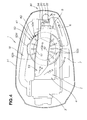
- the generator 40 is covered by a cap-shaped generator cover 50 as shown in FIG. 4.
- the generator cover 50 is comprised of a dome-shaped ceiling part 50a and a peripheral wall 50b.
- the ceiling part 50a has right and left guide walls 51, 52 extending in a front-to-rear direction in spaced apart relation to each other. Between the guide walls, the ceiling part 50a has a rear projection 53 projecting rearwardly and a front projection 54 projecting forwardly up to a front upper part of the intake silencer 6.
- the ceiling part 50a has a plurality of air inlets 50c for introducing cooling air into inside the generator cover 50 for cooling the generator 40.
- a duct 50d is disposed in opposed relation to the intake silencer 6 and the electronic component box 7 and above an inlet manifold 18 for discharging hot air resulted from cooling the generator 40.
- the upper cover 31 of the engine cover 30 has a recessed part 31a formed in a rear half thereof and an outside air inlet 32 formed in a mid-part in a front-and-rear direction of the recessed part 31a and opening upwardly.
- a lid 33 is disposed above the outside air inlet 32 formed in the rear half of the upper cover 31.
- An opening 34 is defined between the lid 33 and the recessed part 31a of the upper cover 31 for allowing outside air to enter inside the engine cover 30. Outside air is introduced through the opening 34 and the outside air inlet 32 into inside the engine cover 30.
- the intake silencer 6, which is box-shaped, is disposed in a right side part of the crankcase 5 such that it occupies an area of the right side part spanning from a front part to a forward part of the latter.
- the intake silencer 6 has an intake port 6a for introducing outside air into inside the engine cover 30.
- the intake port 6a is provided on a surface other than surfaces opposed to the engine 2 and hence to the crankcase 5. In the illustrated example, the intake port 6a is provided in such a manner as to open downwardly.
- the intake silencer 6 also has a discharge port 6b disposed below the intake port 6a for discharging the outside air introduced through the intake port 6a toward a throttle valve apparatus 19.
- the discharge port 6b communicates with an introductory part of the throttle valve apparatus 19 which forms part of a fuel supply apparatus, not shown. Outside air introduced through the intake port 6a is fed to the throttle valve apparatus 19 and then to the inlet manifold 18.
- Part of the wall of the intake silencer 6 suppresses direct entry into the intake port 6a of the air comprised of air which became hot as a result of cooling the generator 40.
- outside air flows into inside the engine cover 30 through the opening 34 defined by the upper cover 31 and the lid 33 and through the outside air inlet 32 formed in the upper cover 31.
- the outside air flew past the outside air inlet 32 flows to above a rear projection 53 of the generator cover 50, as shown by arrow a , flows between the right and left guide walls 51, 51 of the generator cover 50, as shown by arrow b , and flows through a front projection of the generator cover 50 into a forward position of the intake silencer 6, as shown by arrow c.
- the outside air flows through the intake port 6a of the intake silencer 6 into the intake silencer 6 and then into the throttle valve apparatus 19, where it is mixed with a fuel and fed to the inlet manifold 18.
- the outside air flew past the outside air inlet 32 also flows over and alongside the electronic component box 7 and the intake silencer 6 into a space around the engine 2, as shown by arrows d , e and f .
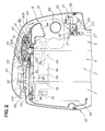
- the electronic components 20 and the water separator 21 are mounted to a front wall 5d of the crankcase 5 such that they are positioned below the intake port 6a of the intake silencer 6, as shown in FIG. 2.
- the electronic components 20 include a pump and a relay switch, the pump being for effecting normal- and counter-drive of the hydraulic apparatus which is comprised of the tilt cylinder 16 and the trim cylinder 17, the relay being for the electric motor.
- the electronic components 20 loathe heat and hence should be kept in an environment that is free from a temperature being increased rapidly. Further, the electronic components 20 require vibration damping.
- both the electronic equipment 20 and the fuel water separator 21 be supported at a single position within the engine unit to thereby simplify the support arrangement for them and to reduce the number of required parts and man hours.
- a bracket 22 for supporting the electronic equipment 20 and the fuel water separator 21 is made by press-forming a steel sheet and is U-shaped as viewed in side elevation with right and left side being opened.
- the support bracket 22 includes an upper wall 22a and a lower wall 22b with their opposite ends having downwardly bent mounting parts 22c (totally four) for mounting the bracket to the front wall 5d of the crankcase 5.
- Each of the mounting parts 22c has a fitting hole 22d within which a vibration damping rubber grommet 25 is to be fitted.
- a bush 24 is fitted into the grommet 25.
- a bolt 27 is threadedly engaged in a threaded hole 5e formed in a front wall 5d of the crankcase 5 with a washer 26 disposed in-between to thereby fixedly secure the bracket 22 to the front surface of the crankcase 5.
- the bracket 22 is supported via the rubber grommet 25 vibration-freely by a vibration source, namely, the engine.
- the electronic equipment 20 has at its lower part a mounting flange 20a extending in a right-and-left direction and mounted via a bolt 28 to a lower wall 22b of the bracket 22 with the result that the equipment 20 is mounted within the bracket 22.
- the fuel water separator 21 is mounted to a front wall 22e of the bracket 22 via an arm member 29. Front part and upper and lower parts of the arm member are opened to form a U-shape as viewed in top plan.
- Body 21a of the water separator 21 is sandwiched between right and left side walls 29a, 29a of the arm member 29. That is, rear surface and right and left side surfaces of the body 21a are enclosed by a rear wall 29b and the right and left side walls 29a, 29a of the arm member 29. Front surface of the body 21a is constricted by a belt 29c extended between front ends of the right and left side walls 29a, 29a of the arm member 29.
- the water separator 21 is thus mounted, via the arm member 29 and the bracket 22, to the front lower part of the crankcase 5. Because the electronic equipment 20 and the water separator 21 are mounted to the engine through the rubber grommet 25, they become resistant to vibrations resulted from the engine drive.
- the water separator is comprised of a body 21a and a lid member 21b removably threaded with an upper part of the body 21a.
- the lid member 21b as shown in FIG. 5, has a fuel inlet 21c and a fuel outlet 21d disposed in juxtaposition.
- a lead switch holder 21f which accommodates a lead switch 21g, extends upwardly from a bottom 21e of the body 21a through the latter. Fitted over an outer periphery of the lead switch holder 21f is a ringshaped magnet float 21h.
- Fuel is fed through the fuel inlet 21c into the body 21a of the water separator 21 and lead out of the fuel outlet 21d. Water contained in the fuel is separated during the fuel flow.
- Separated water is reserved in the body 21a.
- the level of reserved water is detected by a lead switch 21g that detects the rise of the magnet float 21h.
- a time to discharge the separated water is indicated by, e.g., a lamp, a tube, not shown, is removed from the fuel inlet 21c and the fuel outlet 21d, followed by removing the lid member 21b from the body 21a so that the reserved water can be discharged from the body 21a.
- the electronic equipment 20 which comprise plural relay switches with electrical contacts, is mounted via the rubber grommet (mount) 25 to the engine as a source of vibration.
- the electrical contacts of the electronic equipment 20 are freed from undesired effects of vibrations.
- the lead switch 21g disposed in the water or fluid reserved within the water separator 21, it is protected from vibrations dually by the rubber mount 25 and the fluid.
- the electronic equipment 20 is disposed below the intake port 6a formed in the lower surface of the intake silencer 6 which in turn is disposed on the front side of the outboard engine unit, air positioned located below the intake port 6a of the intake silencer 6 flows with the outside air taken in through the intake port 6a so that no air stands still around the electronic equipment 20. Consequently, the electronic equipment 20 is cooled efficiently and heat generation of the equipment 20 is suppressed.
- the electronic components are mounted to the front wall of the crankcase, this should not be construed as the sole mounting mode or position.
- the electronic components may be mounted to the bracket which in turn is mounted via the rubber mount to the mount case for supporting the engine.
- An outboard engine unit (1) having plural electronic components (20, 21) is disclosed.
- the electronic components are wholly supported by a single bracket (22) which is mounted to a crankcase (5) through a vibration damping rubber grommet (25).
Landscapes
- Engineering & Computer Science (AREA)
- Chemical & Material Sciences (AREA)
- Combustion & Propulsion (AREA)
- Mechanical Engineering (AREA)
- General Engineering & Computer Science (AREA)
- Physics & Mathematics (AREA)
- Electromagnetism (AREA)
- Cylinder Crankcases Of Internal Combustion Engines (AREA)
- Vibration Prevention Devices (AREA)
Applications Claiming Priority (1)
| Application Number | Priority Date | Filing Date | Title |
|---|---|---|---|
| JP2006127623A JP2007296997A (ja) | 2006-05-01 | 2006-05-01 | 船外機 |
Publications (2)
| Publication Number | Publication Date |
|---|---|
| EP1852884A1 true EP1852884A1 (de) | 2007-11-07 |
| EP1852884B1 EP1852884B1 (de) | 2011-06-08 |
Family
ID=38171192
Family Applications (1)
| Application Number | Title | Priority Date | Filing Date |
|---|---|---|---|
| EP07008787A Expired - Fee Related EP1852884B1 (de) | 2006-05-01 | 2007-04-30 | Außenbordmotoreinheit |
Country Status (4)
| Country | Link |
|---|---|
| US (1) | US7488227B2 (de) |
| EP (1) | EP1852884B1 (de) |
| JP (1) | JP2007296997A (de) |
| CN (1) | CN101066702B (de) |
Cited By (1)
| Publication number | Priority date | Publication date | Assignee | Title |
|---|---|---|---|---|
| EP3486472A1 (de) * | 2017-11-15 | 2019-05-22 | Toyota Jidosha Kabushiki Kaisha | Befestigungsmechanismus für elektronische ausrüstung für motor |
Families Citing this family (9)
| Publication number | Priority date | Publication date | Assignee | Title |
|---|---|---|---|---|
| JP4785624B2 (ja) * | 2006-05-31 | 2011-10-05 | 本田技研工業株式会社 | 電装ホルダを備える内燃機関 |
| JP5416373B2 (ja) * | 2008-07-22 | 2014-02-12 | ヤマハ発動機株式会社 | 舶用推進機 |
| JP5584189B2 (ja) * | 2011-11-02 | 2014-09-03 | 本田技研工業株式会社 | 船外機の冷却/吸気装置 |
| FR3007080B1 (fr) * | 2013-06-17 | 2019-05-17 | Suzuki Motor Corporation | Structure d'admission de moteur hors-bord |
| DE102016004776A1 (de) * | 2016-04-20 | 2017-10-26 | Neander Motors Ag | Gebläse für ein Luftführungssystem eines Außenbordmotors |
| EP3458355B1 (de) * | 2016-05-18 | 2023-07-05 | ABB Oy | Verfahren und steuerungsanordnung zur steuerung der vibrationen einer antriebseinheit eines schiffs |
| JP2021075167A (ja) * | 2019-11-11 | 2021-05-20 | スズキ株式会社 | 船外機 |
| CN112493499A (zh) * | 2020-12-11 | 2021-03-16 | 昆明理工大学 | 一种倾斜导槽式澳洲坚果螺旋开口机 |
| US12528348B2 (en) * | 2022-08-10 | 2026-01-20 | Nissan North America, Inc. | Airflow regulation assemblies for vehicles including an active grille shutter connected to a reinforcement member |
Citations (4)
| Publication number | Priority date | Publication date | Assignee | Title |
|---|---|---|---|---|
| JPH10223111A (ja) * | 1997-02-03 | 1998-08-21 | Honda Motor Co Ltd | 船外機用リレー |
| US5809974A (en) * | 1996-05-31 | 1998-09-22 | Sanshin Kogyo Kabushiki Kaisha | Engine electrical system |
| US6334420B1 (en) * | 1999-05-31 | 2002-01-01 | Suzuki Kabushiki Kaisha | Outboard motor |
| US20040149241A1 (en) * | 2003-02-05 | 2004-08-05 | Suzuki Motor Corporation | Outboard motor |
Family Cites Families (3)
| Publication number | Priority date | Publication date | Assignee | Title |
|---|---|---|---|---|
| JP3121848B2 (ja) * | 1991-01-28 | 2001-01-09 | 三信工業株式会社 | 電子部品ユニットの船外機用エンジンへの取付構造 |
| JP4067150B2 (ja) * | 1997-06-24 | 2008-03-26 | ヤマハマリン株式会社 | 船外機 |
| JP2000027723A (ja) * | 1998-07-08 | 2000-01-25 | Sanshin Ind Co Ltd | マリンエンジンの燃料フィルタ |
-
2006
- 2006-05-01 JP JP2006127623A patent/JP2007296997A/ja active Pending
-
2007
- 2007-04-27 CN CN2007101047950A patent/CN101066702B/zh not_active Expired - Fee Related
- 2007-04-30 EP EP07008787A patent/EP1852884B1/de not_active Expired - Fee Related
- 2007-05-01 US US11/742,857 patent/US7488227B2/en not_active Expired - Fee Related
Patent Citations (4)
| Publication number | Priority date | Publication date | Assignee | Title |
|---|---|---|---|---|
| US5809974A (en) * | 1996-05-31 | 1998-09-22 | Sanshin Kogyo Kabushiki Kaisha | Engine electrical system |
| JPH10223111A (ja) * | 1997-02-03 | 1998-08-21 | Honda Motor Co Ltd | 船外機用リレー |
| US6334420B1 (en) * | 1999-05-31 | 2002-01-01 | Suzuki Kabushiki Kaisha | Outboard motor |
| US20040149241A1 (en) * | 2003-02-05 | 2004-08-05 | Suzuki Motor Corporation | Outboard motor |
Cited By (2)
| Publication number | Priority date | Publication date | Assignee | Title |
|---|---|---|---|---|
| EP3486472A1 (de) * | 2017-11-15 | 2019-05-22 | Toyota Jidosha Kabushiki Kaisha | Befestigungsmechanismus für elektronische ausrüstung für motor |
| US11168831B2 (en) | 2017-11-15 | 2021-11-09 | Toyota Jidosha Kabushiki Kaisha | Attachment mechanism for electronic equipment for engine |
Also Published As
| Publication number | Publication date |
|---|---|
| EP1852884B1 (de) | 2011-06-08 |
| US7488227B2 (en) | 2009-02-10 |
| US20070251488A1 (en) | 2007-11-01 |
| CN101066702A (zh) | 2007-11-07 |
| CN101066702B (zh) | 2010-06-09 |
| JP2007296997A (ja) | 2007-11-15 |
Similar Documents
| Publication | Publication Date | Title |
|---|---|---|
| EP1852884B1 (de) | Außenbordmotoreinheit | |
| EP1621740B1 (de) | Brennkraftmaschine und Generatorkombination | |
| CA2259790C (en) | Outboard motor | |
| JP3468327B2 (ja) | 4サイクル船外機 | |
| US5203292A (en) | Wiring arrangement for electric parts of an outboard motor | |
| JP3690866B2 (ja) | 船外機のエンジン配置構造 | |
| US9505475B2 (en) | Jet propelled watercraft | |
| JP6734145B2 (ja) | 船外機 | |
| JP2001107740A (ja) | 4サイクルエンジン | |
| JP4629247B2 (ja) | 船外機の冷却通路構造 | |
| US6659221B2 (en) | Engine intake silencer | |
| JPH11301591A (ja) | 船外機 | |
| JP4764264B2 (ja) | 汎用エンジンの電気配線構造 | |
| JP3986262B2 (ja) | 船外機 | |
| JP5617413B2 (ja) | 船外機のマウント冷却構造 | |
| US5967865A (en) | Outboard splash plate arrangement | |
| JP4833724B2 (ja) | 船外機 | |
| US6722305B2 (en) | Electrical equipment arrangement for small watercraft | |
| JP4005198B2 (ja) | 船外機 | |
| EP1069292B1 (de) | Aussenbordmotor | |
| JPH10223111A (ja) | 船外機用リレー | |
| US6053155A (en) | Ignition mounting arrangement for outboard motor | |
| JP4785624B2 (ja) | 電装ホルダを備える内燃機関 | |
| JP2001073750A (ja) | 船外機用エンジンの触媒装置 | |
| JP3881736B2 (ja) | 船外機 |
Legal Events
| Date | Code | Title | Description |
|---|---|---|---|
| PUAI | Public reference made under article 153(3) epc to a published international application that has entered the european phase |
Free format text: ORIGINAL CODE: 0009012 |
|
| 17P | Request for examination filed |
Effective date: 20070430 |
|
| AK | Designated contracting states |
Kind code of ref document: A1 Designated state(s): AT BE BG CH CY CZ DE DK EE ES FI FR GB GR HU IE IS IT LI LT LU LV MC MT NL PL PT RO SE SI SK TR |
|
| AX | Request for extension of the european patent |
Extension state: AL BA HR MK YU |
|
| AKX | Designation fees paid |
Designated state(s): DE FR SE |
|
| 17Q | First examination report despatched |
Effective date: 20080820 |
|
| GRAP | Despatch of communication of intention to grant a patent |
Free format text: ORIGINAL CODE: EPIDOSNIGR1 |
|
| GRAS | Grant fee paid |
Free format text: ORIGINAL CODE: EPIDOSNIGR3 |
|
| RIN1 | Information on inventor provided before grant (corrected) |
Inventor name: KURIYAGAWA, KOJIC/O HONDA R&D CO., LTD., Inventor name: WATANABE, TOSHIYUKIC/O HONDA R&D CO., LTD. Inventor name: FUJIMA, AKIFUMIC/O HONDA R&D CO.,LTD. |
|
| GRAA | (expected) grant |
Free format text: ORIGINAL CODE: 0009210 |
|
| AK | Designated contracting states |
Kind code of ref document: B1 Designated state(s): DE FR SE |
|
| REG | Reference to a national code |
Ref country code: DE Ref legal event code: R096 Ref document number: 602007015017 Country of ref document: DE Effective date: 20110721 |
|
| REG | Reference to a national code |
Ref country code: SE Ref legal event code: TRGR |
|
| PLBE | No opposition filed within time limit |
Free format text: ORIGINAL CODE: 0009261 |
|
| STAA | Information on the status of an ep patent application or granted ep patent |
Free format text: STATUS: NO OPPOSITION FILED WITHIN TIME LIMIT |
|
| 26N | No opposition filed |
Effective date: 20120309 |
|
| REG | Reference to a national code |
Ref country code: DE Ref legal event code: R097 Ref document number: 602007015017 Country of ref document: DE Effective date: 20120309 |
|
| REG | Reference to a national code |
Ref country code: SE Ref legal event code: EUG |
|
| REG | Reference to a national code |
Ref country code: FR Ref legal event code: ST Effective date: 20121228 |
|
| REG | Reference to a national code |
Ref country code: DE Ref legal event code: R119 Ref document number: 602007015017 Country of ref document: DE Effective date: 20121101 |
|
| PG25 | Lapsed in a contracting state [announced via postgrant information from national office to epo] |
Ref country code: FR Free format text: LAPSE BECAUSE OF NON-PAYMENT OF DUE FEES Effective date: 20120430 Ref country code: SE Free format text: LAPSE BECAUSE OF NON-PAYMENT OF DUE FEES Effective date: 20120501 |
|
| PG25 | Lapsed in a contracting state [announced via postgrant information from national office to epo] |
Ref country code: DE Free format text: LAPSE BECAUSE OF FAILURE TO SUBMIT A TRANSLATION OF THE DESCRIPTION OR TO PAY THE FEE WITHIN THE PRESCRIBED TIME-LIMIT Effective date: 20121101 |