EP1852218B1 - Oszillationsantrieb - Google Patents
Oszillationsantrieb Download PDFInfo
- Publication number
- EP1852218B1 EP1852218B1 EP07008184A EP07008184A EP1852218B1 EP 1852218 B1 EP1852218 B1 EP 1852218B1 EP 07008184 A EP07008184 A EP 07008184A EP 07008184 A EP07008184 A EP 07008184A EP 1852218 B1 EP1852218 B1 EP 1852218B1
- Authority
- EP
- European Patent Office
- Prior art keywords
- tool
- oscillation drive
- longitudinal axis
- contact surface
- mounting
- Prior art date
- Legal status (The legal status is an assumption and is not a legal conclusion. Google has not performed a legal analysis and makes no representation as to the accuracy of the status listed.)
- Active
Links
Images


Classifications
-
- B—PERFORMING OPERATIONS; TRANSPORTING
- B24—GRINDING; POLISHING
- B24B—MACHINES, DEVICES, OR PROCESSES FOR GRINDING OR POLISHING; DRESSING OR CONDITIONING OF ABRADING SURFACES; FEEDING OF GRINDING, POLISHING, OR LAPPING AGENTS
- B24B23/00—Portable grinding machines, e.g. hand-guided; Accessories therefor
- B24B23/04—Portable grinding machines, e.g. hand-guided; Accessories therefor with oscillating grinding tools; Accessories therefor
-
- B—PERFORMING OPERATIONS; TRANSPORTING
- B24—GRINDING; POLISHING
- B24B—MACHINES, DEVICES, OR PROCESSES FOR GRINDING OR POLISHING; DRESSING OR CONDITIONING OF ABRADING SURFACES; FEEDING OF GRINDING, POLISHING, OR LAPPING AGENTS
- B24B45/00—Means for securing grinding wheels on rotary arbors
-
- Y—GENERAL TAGGING OF NEW TECHNOLOGICAL DEVELOPMENTS; GENERAL TAGGING OF CROSS-SECTIONAL TECHNOLOGIES SPANNING OVER SEVERAL SECTIONS OF THE IPC; TECHNICAL SUBJECTS COVERED BY FORMER USPC CROSS-REFERENCE ART COLLECTIONS [XRACs] AND DIGESTS
- Y10—TECHNICAL SUBJECTS COVERED BY FORMER USPC
- Y10T—TECHNICAL SUBJECTS COVERED BY FORMER US CLASSIFICATION
- Y10T279/00—Chucks or sockets
- Y10T279/15—Threaded grip
-
- Y—GENERAL TAGGING OF NEW TECHNOLOGICAL DEVELOPMENTS; GENERAL TAGGING OF CROSS-SECTIONAL TECHNOLOGIES SPANNING OVER SEVERAL SECTIONS OF THE IPC; TECHNICAL SUBJECTS COVERED BY FORMER USPC CROSS-REFERENCE ART COLLECTIONS [XRACs] AND DIGESTS
- Y10—TECHNICAL SUBJECTS COVERED BY FORMER USPC
- Y10T—TECHNICAL SUBJECTS COVERED BY FORMER US CLASSIFICATION
- Y10T279/00—Chucks or sockets
- Y10T279/16—Longitudinal screw clamp
-
- Y—GENERAL TAGGING OF NEW TECHNOLOGICAL DEVELOPMENTS; GENERAL TAGGING OF CROSS-SECTIONAL TECHNOLOGIES SPANNING OVER SEVERAL SECTIONS OF THE IPC; TECHNICAL SUBJECTS COVERED BY FORMER USPC CROSS-REFERENCE ART COLLECTIONS [XRACs] AND DIGESTS
- Y10—TECHNICAL SUBJECTS COVERED BY FORMER USPC
- Y10T—TECHNICAL SUBJECTS COVERED BY FORMER US CLASSIFICATION
- Y10T403/00—Joints and connections
- Y10T403/29—Rotarily connected, differentially translatable members, e.g., turn-buckle, etc.
- Y10T403/291—Rotarily connected, differentially translatable members, e.g., turn-buckle, etc. having tool-engaging means or operating handle
-
- Y—GENERAL TAGGING OF NEW TECHNOLOGICAL DEVELOPMENTS; GENERAL TAGGING OF CROSS-SECTIONAL TECHNOLOGIES SPANNING OVER SEVERAL SECTIONS OF THE IPC; TECHNICAL SUBJECTS COVERED BY FORMER USPC CROSS-REFERENCE ART COLLECTIONS [XRACs] AND DIGESTS
- Y10—TECHNICAL SUBJECTS COVERED BY FORMER USPC
- Y10T—TECHNICAL SUBJECTS COVERED BY FORMER US CLASSIFICATION
- Y10T74/00—Machine element or mechanism
- Y10T74/21—Elements
- Y10T74/2164—Cranks and pedals
Definitions
- An oscillation drive is to be understood as meaning a drive whose output shaft executes an oscillating rotational movement during operation.
- a fixed to the output shaft tool can be used in a variety of ways, such as for sawing, cutting or grinding.
- a first variant the tool is pressed with a clamping element, for example by means of a clamping screw, against a receptacle at the free end of the output shaft, so that a high frictional force between the tool and the recording arises.
- a clamping element for example by means of a clamping screw
- Such a connection is referred to as frictional.
- the receptacle or the tool on a mounting portion which can engage in a correspondingly shaped mounting opening on the other part.
- the transmission of the torque is achieved here by a form fit between the mounting portion and mounting hole.
- a positive connection offers over a frictional connection the advantage that even very high torques can be transmitted.
- the oscillation drive according to the invention combines the advantages of a positive connection, namely the possibility of transmitting high torques, with the advantages of a frictional connection, namely that overloads are avoided.
- the transmission of the torque takes place in principle positive fit by a positive connection between the mounting portion of the output shaft and the mounting opening of the tool.
- the oscillation drive according to the invention allows a certain axial deflection of the tool with respect to the longitudinal axis of the output shaft. Due to the axial deflection of the tool, the tool moves into a region of the mounting portion, which allows a rotation of the tool by a certain angle of rotation.
- the fastening means presses the tool back into its form-fitting starting position.
- the force which opposes the fastening means of the axial displacement of the tool is achieved in that the fastening means has an elastic and / or resilient part or is elastically and / or resiliently received.
- the fastener elastically and / or resiliently presses against the tool and holds it in positive fit.
- the tool presses against the force exerted by the fastener, so that in a sense a part of the force acting on the attachment portion force is directed against the fastener , The axial deflection of the tool increases the force exerted by the fastener force and pushes the tool back into the secure positive fit as soon as the increased load decreases.
- the attachment portion widens in a direction parallel to the longitudinal axis and on the contact surface to at least in one area.
- the width of the attachment portion is determined in a plane perpendicular to the longitudinal axis and measured along a circular arc whose center lies on the longitudinal axis. The widening of the fastening section in the direction of the contact surface can thus be described such that the width of the fastening section in a first plane perpendicular to the longitudinal axis is greater than the width in a parallel plane which is farther away from the contact surface than the first plane.
- attachment portion narrows or tapers in at least one region away from the contact surface in one direction.
- this may mean that the base surface of the fastening section, with which the fastening section rests on the contact surface, is larger than the surface of the fastening section facing away from the base surface. If the surfaces mentioned are not flat, the respective surface dimension is to be considered in relation to a plane perpendicular to the longitudinal axis.
- the attachment portion has a plurality of projections which protrude radially outwardly with respect to the longitudinal axis.
- each projection forms, starting from the contact surface, at least one flank whose base line is a straight path on the contact surface.
- a corresponding contact surface should also be formed with a straight base line at the attachment opening of the tool. Then the torque transmission can take place along the entire straight line. This can eliminate punctiform stresses between the fastener and the mounting hole, so that areas with a particularly high heat load can be avoided.
- the surface of the flank forms a flat trapezoid.
- the surface of the flank is designed in such a way, upon rotation of the tool a particularly good sliding of the part of the fastening opening corresponding to this flank is possible. Furthermore, it is advantageous in this embodiment that the sliding of the part of the attachment opening and thus the axial Dodge of the tool is approximately proportional to the force acting on the tool in the oscillation plane. That is, the higher the load on the tool, the further the tool can yield axially.
- the flank to the longitudinal axis forms an angle between 5 ° and 40 °, preferably between 10 ° and 25 °, in particular between 13 ° and 17 °.
- the angle can be chosen in view of the intended material pairing, e.g. Steel on steel or steel on aluminum.
- the output shaft on a biased by a spring element tension element on which the fastening means can be fixed.
- the fastening means for example, a fastening pin, held by the substantially rigid tension member, wherein the tension element is in turn held by means of the spring element resiliently in the oscillation drive.
- the principle of such a structure is for example from the DE 39 02 874 A1 known.
- the fastening means on an elastic and / or resilient portion.
- the tool is held by a member that allows the axial deflection of the tool due to a partially elastic and / or resilient property.
- a fastening means can for example represent a clamping screw whose screw head has a certain elasticity or is elastically displaceable with respect to the screw shaft.
- the attachment portion is polygonal in cross-section, preferably formed hexagonal.
- the projections are symmetrical with respect to a direction radial to the longitudinal axis and each have two flanks, which are connected to each other via a remote from the longitudinal axis, common, curved portion.
- flanks approach at an angle between 5 ° and 35 °, preferably between 10 ° and 25 °, in particular between 12 ° and 18 °.
- flanks of the projections are closed in an area near the longitudinal axis by an undercut.
- the torque transmission does not take place in the innermost region of the projection, which is seen radially from the longitudinal axis, but in its middle, and possibly also in its outer region.
- Fig. 1a shows an oscillating drive 10 with an output shaft 12 which is driven to oscillate about its longitudinal axis 14 and has a free end 16.
- a receptacle 18 is arranged, which has a contact surface 20 for engaging a tool 22 (FIG. Fig. 3 ) having.
- a section of the receptacle 18 is in the Fig. 1b shown enlarged.
- a fastening portion 24 is arranged, which protrudes outwards in relation to the contact surface 20 in the direction of the longitudinal axis 14 to the outside and for the positive connection with a mounting opening 26 (FIG. Fig. 3 ) of a voltage applied to the contact surface 20 tool 22 is formed.
- the oscillating drive 10 also has a quick-release device 29 with a tensioning lever 30, by means of which a tension element 31 received in the output shaft 12 can be axially displaced between a working position and a rest position.
- a fastening means 28 can be fastened approximately in the form of a screw, which passes through a fastening opening 26 of a tool 22 placed on the fastening section 24.
- the tension element 31 In the rest position, the tension element 31 is pushed axially outwardly by the tensioning lever 30, so that in this position the fastening means 28 can be released without the aid of a hand tool in order to change the tool 22.
- the tension element 31 reaches the working position, in which now the tension element 31 is stretched by the action of a spring element 32, so that the fastening means 28 and thus the tool 22 under the action of the spring element 32 against the contact surface 20 of the recording 18 is biased.
- the fastening means 28 is here indicated in the form of a pin 34 inserted into the tension element 31 with a head 35.
- the resilient attachment of the fastener 28 results in that the fastener 28 can also be displaced against the force exerted by the spring element 30, i. away from the contact surface 20, when a correspondingly large force is exerted on the fastening means 28.
- either the pulling element 31 or the fastening means 28 permits axial deflection of the tool 22.
- the force required to move counter to Preloading the fastener 28 results from the torque acting between the output shaft 12 and the tool 22, as will be explained in more detail below.
- the attachment portion 24 here has four projections 36, which are each arranged at an angle of 90 ° to each other about the longitudinal axis 14. (One of the projections 36 is hidden here.) The projections 36 are each connected via a concentric to the longitudinal axis 14 arc-like portion 44. Overall, it should be noted that the attachment portion 24 widens in a direction parallel to the longitudinal axis 14 and on the contact surface 20.
- the projections 36 are symmetrical with respect to a radial direction to the longitudinal axis 14 and each have two flanks 38, which facing away from the longitudinal axis 14 , common, curved portion 42 are interconnected.
- the baseline 40 of the flanks 38 on the contact surface 20 is in each case a straight line.
- the flanks 38 form in a side view approximately according to Fig. 1a, b each a flat harness.
- the angle ⁇ formed by a flank 38 to the longitudinal axis 14 is here about 15 °.
- the angle ⁇ at the rounding of the projection 36 is here also about 15 °, but if necessary, it can also be selected differently from the angle ⁇ .
- the projection 36 tapers in the radial direction from the longitudinal axis 14 to the outside.
- the taper is achieved by the planar flanks 38 approaching radially outward.
- the angle ⁇ between the two flat flanks 38 is approximately 15 ° here.
- flanks 38 of the projections 36 are in an area near the longitudinal axis 14 in each case by an undercut 46 completed. This can cause the power transmission between the output shaft 12 and the tool 22 takes place mainly or exclusively along the flanks 38.
- Fig. 3 shows the oscillating drive 10 with attached tool 22.
- the mounting hole 26 has eight receptacles, the shape and size of the projections 36 is adapted so that the tool 22 - as shown by the dashed line - can be placed in different positions.
- the oscillation direction of the oscillation drive 10 is indicated by means of the double arrow 48.
- Fig. 4 shows the receptacle 18 with an attached tool 22, wherein the tool 22 is pressed by the fastening means 28 against the contact surface 20.
- edges 50 of the attachment opening 26 of the tool 22 in the region of the baseline 40 abut the projection 36. In this way, a positive transmission of the torque from the output shaft 12 takes place on the tool 22.
- the oblique flank 38 causes the force which hitherto has been applied in a plane perpendicular to the longitudinal axis 14 to the fastening section 24, in particular to the projections 36, to be partially converted into a force acting axially to the longitudinal axis 14.
- This axially acting force is indicated by the arrow 52.
- the remaining, acting transversely to the longitudinal axis 14 force component is shown by the arrow 54.
- the force acting on the tool 22 causes it to slide with its attachment opening 26 along the flank 38.
- the tool 22 pushes against the bias of the fastener 28, while the force component 54 leads to the rotation of the tool 22 by the twist angle ⁇ .
- the rotation can take place when the axial force component 52 exceeds the bias caused by the spring element.
- the compliance can be realized advantageously with an oscillating drive 10 with a quick-release device 28, since the existing spring element 32 can be used to achieve the axial mobility.
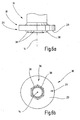
- Fig. 6a and 6b show by way of example an alternative embodiment of the receptacle 18 with a mounting portion 24 in the form of a hexagon.
Landscapes
- Engineering & Computer Science (AREA)
- Mechanical Engineering (AREA)
- Details Of Spanners, Wrenches, And Screw Drivers And Accessories (AREA)
- Clamps And Clips (AREA)
- Surgical Instruments (AREA)
- Constituent Portions Of Griding Lathes, Driving, Sensing And Control (AREA)
- Reciprocating, Oscillating Or Vibrating Motors (AREA)
- Fuel-Injection Apparatus (AREA)
- Glass Compositions (AREA)
- Gripping On Spindles (AREA)
- Dry Shavers And Clippers (AREA)
- Turbine Rotor Nozzle Sealing (AREA)
Priority Applications (3)
| Application Number | Priority Date | Filing Date | Title |
|---|---|---|---|
| DE202007019145U DE202007019145U1 (de) | 2006-05-04 | 2007-04-23 | Oszillationsantrieb |
| EP10004390.0A EP2208576B2 (de) | 2006-05-04 | 2007-04-23 | Oszillationsantrieb |
| PL07008184T PL1852218T3 (pl) | 2006-05-04 | 2007-04-23 | Napęd oscylacyjny |
Applications Claiming Priority (1)
| Application Number | Priority Date | Filing Date | Title |
|---|---|---|---|
| DE102006021969A DE102006021969A1 (de) | 2006-05-04 | 2006-05-04 | Oszillationsantrieb |
Related Child Applications (1)
| Application Number | Title | Priority Date | Filing Date |
|---|---|---|---|
| EP10004390.0A Division EP2208576B2 (de) | 2006-05-04 | 2007-04-23 | Oszillationsantrieb |
Publications (2)
| Publication Number | Publication Date |
|---|---|
| EP1852218A1 EP1852218A1 (de) | 2007-11-07 |
| EP1852218B1 true EP1852218B1 (de) | 2010-06-02 |
Family
ID=38043034
Family Applications (2)
| Application Number | Title | Priority Date | Filing Date |
|---|---|---|---|
| EP07008184A Active EP1852218B1 (de) | 2006-05-04 | 2007-04-23 | Oszillationsantrieb |
| EP10004390.0A Active EP2208576B2 (de) | 2006-05-04 | 2007-04-23 | Oszillationsantrieb |
Family Applications After (1)
| Application Number | Title | Priority Date | Filing Date |
|---|---|---|---|
| EP10004390.0A Active EP2208576B2 (de) | 2006-05-04 | 2007-04-23 | Oszillationsantrieb |
Country Status (8)
| Country | Link |
|---|---|
| US (1) | US7997586B2 (pl) |
| EP (2) | EP1852218B1 (pl) |
| CN (1) | CN100534708C (pl) |
| AT (1) | ATE469728T1 (pl) |
| DE (4) | DE102006021969A1 (pl) |
| DK (1) | DK1852218T3 (pl) |
| ES (1) | ES2346152T3 (pl) |
| PL (1) | PL1852218T3 (pl) |
Cited By (14)
| Publication number | Priority date | Publication date | Assignee | Title |
|---|---|---|---|---|
| USD651876S1 (en) | 2010-12-14 | 2012-01-10 | Techtronic Power Tools Technology Limited | Universal interface for accessory blades |
| USD651874S1 (en) | 2010-12-14 | 2012-01-10 | Techtronic Power Tools Technology Limited | Universal interface for accessory blades |
| USD651878S1 (en) | 2010-12-14 | 2012-01-10 | Techtronic Power Tools Technology Limited | Universal interface for accessory blades |
| USD651875S1 (en) | 2010-12-14 | 2012-01-10 | Techtronic Power Tools Technology Limited | Universal interface for accessory blades |
| USD651877S1 (en) | 2010-12-14 | 2012-01-10 | Techtronic Power Tools Technology Limited | Universal interface for accessory blades |
| USD652274S1 (en) | 2010-12-14 | 2012-01-17 | Techtronic Power Tools Technology Limited | Universal interface for accessory blades |
| USD694076S1 (en) | 2012-06-25 | 2013-11-26 | Techtronic Power Tools Technology Limited | Universal interface for accessory blades |
| USD694596S1 (en) | 2012-06-25 | 2013-12-03 | Techtronic Power Tools Technology Limited | Universal interface for accessory blades |
| USD694598S1 (en) | 2012-06-25 | 2013-12-03 | Techtronic Power Tools Technology Limited | Universal interface for accessory blades |
| USD694599S1 (en) | 2012-06-25 | 2013-12-03 | Techtronic Power Tools Technology Limited | Universal interface for accessory blades |
| USD694597S1 (en) | 2012-06-25 | 2013-12-03 | Techtronic Power Tools Technology Limited | Universal interface for accessory blades |
| US9545699B2 (en) | 2012-02-03 | 2017-01-17 | Makita Corporation | Work tool |
| US9555554B2 (en) | 2013-05-06 | 2017-01-31 | Milwaukee Electric Tool Corporation | Oscillating multi-tool system |
| US11045939B2 (en) | 2018-03-28 | 2021-06-29 | Makita Corporation | Power tool |
Families Citing this family (45)
| Publication number | Priority date | Publication date | Assignee | Title |
|---|---|---|---|---|
| DE202008001759U1 (de) * | 2008-02-01 | 2009-06-04 | C. & E. Fein Gmbh | Oszillierend antreibbare Werkzeugmaschine |
| DE202008011959U1 (de) * | 2008-08-29 | 2010-02-11 | C. & E. Fein Gmbh | Adapter zum Befestigen eines Werkzeugs an einem Oszillationsantrieb |
| DE202009001440U1 (de) * | 2009-01-30 | 2010-07-01 | C. & E. Fein Gmbh | Kraftgetriebenes Handwerkzeug mit Spanneinrichtung für ein Werkzeug |
| CN201597020U (zh) * | 2009-07-01 | 2010-10-06 | 蔡吕乾 | 一种摆式工具工作头 |
| CN101987424B (zh) * | 2009-07-30 | 2012-09-26 | 中国商用飞机有限责任公司 | 数控机床主轴体的摆角校正方法 |
| USD619152S1 (en) | 2009-12-18 | 2010-07-06 | Techtronic Power Tools Technology Limited | Adapter |
| USD623034S1 (en) | 2009-12-18 | 2010-09-07 | Techtronic Power Tools Technology Limited | Tool arbor |
| US9073195B2 (en) | 2010-04-29 | 2015-07-07 | Black & Decker Inc. | Universal accessory for oscillating power tool |
| US9186770B2 (en) | 2010-04-29 | 2015-11-17 | Black & Decker Inc. | Oscillating tool attachment feature |
| AU2013100337B4 (en) * | 2010-04-29 | 2015-11-19 | Black & Decker, Inc. | Power hand tool |
| US8925931B2 (en) | 2010-04-29 | 2015-01-06 | Black & Decker Inc. | Oscillating tool |
| US20130193655A1 (en) * | 2010-04-29 | 2013-08-01 | Black & Decker Inc. | Oscillating Tool Adapter |
| US8616562B2 (en) * | 2010-06-16 | 2013-12-31 | Robert Bosch Gmbh | Adapter for coupling an accessory tool to a drive member of a power tool |
| USD651499S1 (en) * | 2010-08-13 | 2012-01-03 | Dai Tong | Tool head plate |
| USD653523S1 (en) | 2010-09-29 | 2012-02-07 | Milwaukee Electric Tool Corporation | Adapter for a tool |
| USD651062S1 (en) | 2010-09-29 | 2011-12-27 | Milwaukee Electric Tool Corporation | Tool interface for an accessory |
| USD646542S1 (en) | 2010-09-29 | 2011-10-11 | Milwaukee Electric Tool Corporation | Accessory interface for a tool |
| US9149923B2 (en) | 2010-11-09 | 2015-10-06 | Black & Decker Inc. | Oscillating tools and accessories |
| DE102010064366B4 (de) * | 2010-12-30 | 2022-02-03 | Robert Bosch Gmbh | Handwerkzeugmaschinenspannvorrichtung |
| US9174354B2 (en) | 2011-05-18 | 2015-11-03 | Chevron (Hk) Limited | Power tool |
| EP2762276B1 (en) * | 2011-09-29 | 2016-07-27 | Positec Power Tools (Suzhou) Co., Ltd | Multifunctional machine |
| DE102012007924B4 (de) * | 2012-04-17 | 2019-12-05 | C. & E. Fein Gmbh | Handwerkzeug mit einer Spannvorrichtung |
| DE102012007930A1 (de) * | 2012-04-17 | 2013-10-17 | C. & E. Fein Gmbh | Handwerkzeug |
| DE102012007931A1 (de) * | 2012-04-17 | 2013-10-17 | C. & E. Fein Gmbh | Handwerkzeug |
| USD682652S1 (en) | 2012-05-14 | 2013-05-21 | Campbell Hausfeld/Scott Fetzer Company | Tool accessory hub |
| USD682651S1 (en) | 2012-05-14 | 2013-05-21 | Campbell Hausfeld/Scott Fetzer Company | Accessory interface for a tool |
| USD832666S1 (en) | 2012-07-16 | 2018-11-06 | Black & Decker Inc. | Oscillating saw blade |
| DE102012215950B4 (de) * | 2012-09-10 | 2023-11-02 | Robert Bosch Gmbh | Wechselwerkzeug, Werkzeughalter, Handwerkzeug und Werkzeugsystem |
| US9339927B2 (en) * | 2012-12-29 | 2016-05-17 | Chervon (Hk) Limited | Accessory clamping mechanism and power tool having the same |
| NO2884309T3 (pl) * | 2013-08-01 | 2018-09-08 | ||
| DE202013006900U1 (de) * | 2013-08-01 | 2014-11-03 | C. & E. Fein Gmbh | Werkzeugmaschine |
| DE202013006920U1 (de) * | 2013-08-01 | 2014-11-03 | C. & E. Fein Gmbh | Werkzeugeinrichtung |
| US10493544B2 (en) * | 2016-02-05 | 2019-12-03 | Textron Innovations, Inc. | System and method for cutting composite materials |
| DE102017007351A1 (de) | 2016-12-14 | 2018-06-14 | Udo Zirden | Werkzeugblatt |
| USD814900S1 (en) | 2017-01-16 | 2018-04-10 | Black & Decker Inc. | Blade for oscillating power tools |
| US10265778B2 (en) | 2017-01-16 | 2019-04-23 | Black & Decker Inc. | Accessories for oscillating power tools |
| US10843282B2 (en) * | 2017-08-16 | 2020-11-24 | Imperial Blades | Oscillating blade with universal arbor engagement portion |
| US10870155B2 (en) | 2018-02-10 | 2020-12-22 | Robert Bosch Tool Corporation | Oscillating tool accessory holder mechanism |
| US11660690B2 (en) | 2019-11-28 | 2023-05-30 | Makita Corporation | Power tool |
| US11590593B2 (en) | 2019-11-28 | 2023-02-28 | Makita Corporation | Power tool |
| JP7422538B2 (ja) | 2019-12-26 | 2024-01-26 | 株式会社マキタ | 作業工具 |
| JP7330914B2 (ja) | 2020-02-13 | 2023-08-22 | 株式会社マキタ | 振動工具 |
| CN112846972B (zh) * | 2021-01-11 | 2022-10-21 | 烟台鑫硕机械有限公司 | 一种立式圆台平面磨床砂轮紧固装置 |
| US12083610B2 (en) | 2022-11-14 | 2024-09-10 | Robert Bosch Tool Corporation | Tool accessory mounting interface |
| US12194552B2 (en) | 2022-11-14 | 2025-01-14 | Robert Bosch Tool Corporation | Tool accessory mounting interface |
Family Cites Families (22)
| Publication number | Priority date | Publication date | Assignee | Title |
|---|---|---|---|---|
| US1947662A (en) † | 1933-02-20 | 1934-02-20 | Ind Of America Inc | Means for fastening wheels to spindles |
| ES175294Y (es) * | 1971-06-26 | 1973-02-16 | Abrasivi Mapelli Di Grottolo Geometra Arnaldo | Util portaabrasivas perfeccionado para maquinas pulidoras de marmoles, granitos y similares. |
| DE3012836C2 (de) * | 1980-04-02 | 1985-09-26 | Licentia Patent-Verwaltungs-Gmbh, 6000 Frankfurt | Einrichtung zum Festspannen der Schleifscheibe von Winkelschleifern |
| EP0244465B1 (de) | 1985-11-15 | 1989-08-02 | C. & E. FEIN GmbH & Co. | Handschleifgerät |
| DE3806145A1 (de) * | 1988-02-26 | 1989-09-07 | Kress Elektrik Gmbh & Co | Taumelscheibe fuer elektrohandwerkzeuge |
| DE3902874A1 (de) | 1989-02-01 | 1990-08-09 | Fein C & E | Adapter zum befestigen eines zusatzwerkzeugs |
| DE4336620C2 (de) † | 1993-10-27 | 1997-07-03 | Fein C & E | Elektrowerkzeug mit einer nur bei ausgeschaltetem Motor betätigbaren Spannvorrichtung |
| US5489285A (en) † | 1994-02-23 | 1996-02-06 | Hall Surgical, Div. Of Zimmer, Inc. | Surgical saw blade and clamp |
| JP2000190155A (ja) * | 1998-10-14 | 2000-07-11 | Disco Abrasive Syst Ltd | ハブブレ―ド |
| US6547651B1 (en) | 1999-11-10 | 2003-04-15 | Strasbaugh | Subaperture chemical mechanical planarization with polishing pad conditioning |
| US7013987B2 (en) * | 2000-09-08 | 2006-03-21 | Black & Decker | Clutch assembly and clamp mechanism for rotary tool disc |
| US6945862B2 (en) * | 2000-12-07 | 2005-09-20 | C. & E. Fein Gmbh | Power tool having a receptacle for securing a tool |
| DE10061559A1 (de) | 2000-12-07 | 2002-06-13 | C & E Fein Gmbh & Co Kg | Aufnahme zur Befestigung eines Werkzeuges an einer Antriebswelle und Adapter hierzu |
| DE20117159U1 (de) * | 2001-10-16 | 2002-02-14 | C. & E. Fein GmbH & Co KG, 70176 Stuttgart | Werkzeugmaschine mit Befestigungsflansch |
| DE10225051A1 (de) * | 2002-06-06 | 2004-01-08 | Robert Bosch Gmbh | Einsatzwerkzeug mit einer Befestigungseinheit |
| US7189239B2 (en) * | 2003-01-14 | 2007-03-13 | Synvasive Technology, Inc. A California Corporation | Saw blade having a prearranged hub section |
| DE10352501A1 (de) * | 2003-11-11 | 2005-06-02 | Robert Bosch Gmbh | Schleiftelleraufnahme für ein handgeführtes Elektroschleifwerkzeug |
| DE102004020982A1 (de) * | 2004-04-23 | 2005-11-17 | C. & E. Fein Gmbh | Kraftgetriebenes Handwerkzeug mit Spanneinrichtung für ein Werkzeug |
| DE102004050798A1 (de) * | 2004-10-19 | 2006-04-20 | Robert Bosch Gmbh | Vorrichtung zum Befestigen eines Werkzeugs an einer oszillierend antreibbaren Antriebswelle einer Handwerkzeugmaschine |
| EP2594208B1 (en) * | 2005-07-14 | 2015-08-19 | Stryker Corporation | Surgical sagittal saw including a low slap blade mount |
| DE202006001643U1 (de) * | 2006-01-31 | 2006-03-23 | Honnet, Michael, Dipl.-Kaufm. (FH) | Zentrierpuck für Excenterschleifscheiben |
| DE102007035045A1 (de) * | 2007-07-19 | 2009-01-29 | C. & E. Fein Gmbh | Kraftgetriebenes Handwerkzeug |
-
2006
- 2006-05-04 DE DE102006021969A patent/DE102006021969A1/de not_active Withdrawn
-
2007
- 2007-04-20 CN CNB2007101008725A patent/CN100534708C/zh not_active Expired - Fee Related
- 2007-04-23 DK DK07008184.9T patent/DK1852218T3/da active
- 2007-04-23 DE DE202007019145U patent/DE202007019145U1/de not_active Expired - Lifetime
- 2007-04-23 EP EP07008184A patent/EP1852218B1/de active Active
- 2007-04-23 DE DE502007003988T patent/DE502007003988D1/de active Active
- 2007-04-23 ES ES07008184T patent/ES2346152T3/es active Active
- 2007-04-23 EP EP10004390.0A patent/EP2208576B2/de active Active
- 2007-04-23 DE DE202007018679U patent/DE202007018679U1/de not_active Expired - Lifetime
- 2007-04-23 AT AT07008184T patent/ATE469728T1/de active
- 2007-04-23 PL PL07008184T patent/PL1852218T3/pl unknown
- 2007-05-04 US US11/744,321 patent/US7997586B2/en active Active
Cited By (15)
| Publication number | Priority date | Publication date | Assignee | Title |
|---|---|---|---|---|
| USD651874S1 (en) | 2010-12-14 | 2012-01-10 | Techtronic Power Tools Technology Limited | Universal interface for accessory blades |
| USD651878S1 (en) | 2010-12-14 | 2012-01-10 | Techtronic Power Tools Technology Limited | Universal interface for accessory blades |
| USD651875S1 (en) | 2010-12-14 | 2012-01-10 | Techtronic Power Tools Technology Limited | Universal interface for accessory blades |
| USD651877S1 (en) | 2010-12-14 | 2012-01-10 | Techtronic Power Tools Technology Limited | Universal interface for accessory blades |
| USD652274S1 (en) | 2010-12-14 | 2012-01-17 | Techtronic Power Tools Technology Limited | Universal interface for accessory blades |
| USD651876S1 (en) | 2010-12-14 | 2012-01-10 | Techtronic Power Tools Technology Limited | Universal interface for accessory blades |
| US9545699B2 (en) | 2012-02-03 | 2017-01-17 | Makita Corporation | Work tool |
| US10144110B2 (en) | 2012-02-03 | 2018-12-04 | Makita Corporation | Work tool |
| USD694076S1 (en) | 2012-06-25 | 2013-11-26 | Techtronic Power Tools Technology Limited | Universal interface for accessory blades |
| USD694599S1 (en) | 2012-06-25 | 2013-12-03 | Techtronic Power Tools Technology Limited | Universal interface for accessory blades |
| USD694597S1 (en) | 2012-06-25 | 2013-12-03 | Techtronic Power Tools Technology Limited | Universal interface for accessory blades |
| USD694598S1 (en) | 2012-06-25 | 2013-12-03 | Techtronic Power Tools Technology Limited | Universal interface for accessory blades |
| USD694596S1 (en) | 2012-06-25 | 2013-12-03 | Techtronic Power Tools Technology Limited | Universal interface for accessory blades |
| US9555554B2 (en) | 2013-05-06 | 2017-01-31 | Milwaukee Electric Tool Corporation | Oscillating multi-tool system |
| US11045939B2 (en) | 2018-03-28 | 2021-06-29 | Makita Corporation | Power tool |
Also Published As
| Publication number | Publication date |
|---|---|
| EP2208576A3 (de) | 2010-12-29 |
| DE502007003988D1 (de) | 2010-07-15 |
| EP2208576A2 (de) | 2010-07-21 |
| DE202007018679U1 (de) | 2009-01-22 |
| US7997586B2 (en) | 2011-08-16 |
| PL1852218T3 (pl) | 2010-12-31 |
| ATE469728T1 (de) | 2010-06-15 |
| EP1852218A1 (de) | 2007-11-07 |
| DE202007019145U1 (de) | 2010-09-30 |
| US20070295156A1 (en) | 2007-12-27 |
| DK1852218T3 (da) | 2010-10-04 |
| CN101066577A (zh) | 2007-11-07 |
| ES2346152T3 (es) | 2010-10-11 |
| DE102006021969A1 (de) | 2007-11-08 |
| EP2208576B1 (de) | 2013-06-19 |
| CN100534708C (zh) | 2009-09-02 |
| EP2208576B2 (de) | 2017-08-16 |
Similar Documents
| Publication | Publication Date | Title |
|---|---|---|
| EP2208576B1 (de) | Oszillationsantrieb | |
| DE112011103744B4 (de) | Wechselhaltersystem für einen Meißel | |
| EP2880334B1 (de) | Ringmutter | |
| EP0175856B1 (de) | Spannmuffe mit einer Spannschraube | |
| EP1531023A2 (de) | Bohrplatte welche klemmend in einem Grundkörper befestigt ist | |
| DE2857679A1 (de) | Injection nozzle clamp | |
| EP3898057B1 (de) | Ultraschallschweissanlage mit abstützelement | |
| WO2020126842A1 (de) | ULTRASCHALLSCHWEIßANLAGE MIT HALTERUNG | |
| WO2020126836A2 (de) | Ultraschallschweissanlage mit formschlüssiger verbindung | |
| EP3898010B1 (de) | Ultraschallschweissanlage mit einer winkelpositionierungsvorrichtung | |
| DE2708538B2 (de) | Verbindung zwischen den Kettengliedern einer Gleiskette | |
| DE19720412A1 (de) | Zweischneidiger, mit einer einzelnen Schneidplatte versehener Fräser erhöhter Festigkeit und Genauigkeit | |
| DE10162910B4 (de) | Klemmspaltmutter | |
| EP0285704A2 (de) | Mehrteiliges Spannsystem, insbesondere für rundlaufende Werkzeuge | |
| DE29805045U1 (de) | Kunststoffmutter | |
| DE20302843U1 (de) | Arretierungseinheit zur Sicherung einer Wellenmutter auf einem Wellengewinde | |
| CH695099A5 (de) | Spannvorrichtung, insbesondere für handgeführte Elektrowerkzeuge. | |
| DE102009043685B4 (de) | Baugruppe mit Sicherungsmittel | |
| DE69904594T2 (de) | Schnellkuppelsystem für Sägeblätter einer Kreissäge | |
| EP3162503B1 (de) | Kettenspannvorrichtung | |
| EP4508340B1 (de) | Befestiger | |
| DE20122817U1 (de) | Aufnahme zur Befestigung eines Werkzeuges an einer Antriebswelle und Adapter hierzu | |
| EP3360646B1 (de) | Spannwerkzeug und spannwerkzeug-lagerkörperteil | |
| DE1188378B (de) | Befestigungsvorrichtung | |
| WO2023285237A1 (de) | Bremsträger und scheibenbremse |
Legal Events
| Date | Code | Title | Description |
|---|---|---|---|
| PUAI | Public reference made under article 153(3) epc to a published international application that has entered the european phase |
Free format text: ORIGINAL CODE: 0009012 |
|
| AK | Designated contracting states |
Kind code of ref document: A1 Designated state(s): AT BE BG CH CY CZ DE DK EE ES FI FR GB GR HU IE IS IT LI LT LU LV MC MT NL PL PT RO SE SI SK TR |
|
| AX | Request for extension of the european patent |
Extension state: AL BA HR MK YU |
|
| 17P | Request for examination filed |
Effective date: 20080311 |
|
| AKX | Designation fees paid |
Designated state(s): AT BE BG CH CY CZ DE DK EE ES FI FR GB GR HU IE IS IT LI LT LU LV MC MT NL PL PT RO SE SI SK TR |
|
| GRAP | Despatch of communication of intention to grant a patent |
Free format text: ORIGINAL CODE: EPIDOSNIGR1 |
|
| GRAS | Grant fee paid |
Free format text: ORIGINAL CODE: EPIDOSNIGR3 |
|
| GRAA | (expected) grant |
Free format text: ORIGINAL CODE: 0009210 |
|
| AK | Designated contracting states |
Kind code of ref document: B1 Designated state(s): AT BE BG CH CY CZ DE DK EE ES FI FR GB GR HU IE IS IT LI LT LU LV MC MT NL PL PT RO SE SI SK TR |
|
| REG | Reference to a national code |
Ref country code: GB Ref legal event code: FG4D Free format text: NOT ENGLISH |
|
| REG | Reference to a national code |
Ref country code: CH Ref legal event code: EP |
|
| REG | Reference to a national code |
Ref country code: IE Ref legal event code: FG4D Free format text: LANGUAGE OF EP DOCUMENT: GERMAN |
|
| REF | Corresponds to: |
Ref document number: 502007003988 Country of ref document: DE Date of ref document: 20100715 Kind code of ref document: P |
|
| PLBI | Opposition filed |
Free format text: ORIGINAL CODE: 0009260 |
|
| REG | Reference to a national code |
Ref country code: NL Ref legal event code: T3 |
|
| REG | Reference to a national code |
Ref country code: SE Ref legal event code: TRGR |
|
| REG | Reference to a national code |
Ref country code: CH Ref legal event code: NV Representative=s name: AMMANN PATENTANWAELTE AG BERN |
|
| REG | Reference to a national code |
Ref country code: DK Ref legal event code: T3 |
|
| 26 | Opposition filed |
Opponent name: HOME TEC GMBH Effective date: 20100827 |
|
| REG | Reference to a national code |
Ref country code: ES Ref legal event code: FG2A Ref document number: 2346152 Country of ref document: ES Kind code of ref document: T3 |
|
| PG25 | Lapsed in a contracting state [announced via postgrant information from national office to epo] |
Ref country code: LT Free format text: LAPSE BECAUSE OF FAILURE TO SUBMIT A TRANSLATION OF THE DESCRIPTION OR TO PAY THE FEE WITHIN THE PRESCRIBED TIME-LIMIT Effective date: 20100602 |
|
| LTIE | Lt: invalidation of european patent or patent extension |
Effective date: 20100602 |
|
| PG25 | Lapsed in a contracting state [announced via postgrant information from national office to epo] |
Ref country code: SI Free format text: LAPSE BECAUSE OF FAILURE TO SUBMIT A TRANSLATION OF THE DESCRIPTION OR TO PAY THE FEE WITHIN THE PRESCRIBED TIME-LIMIT Effective date: 20100602 Ref country code: LV Free format text: LAPSE BECAUSE OF FAILURE TO SUBMIT A TRANSLATION OF THE DESCRIPTION OR TO PAY THE FEE WITHIN THE PRESCRIBED TIME-LIMIT Effective date: 20100602 |
|
| PG25 | Lapsed in a contracting state [announced via postgrant information from national office to epo] |
Ref country code: CY Free format text: LAPSE BECAUSE OF FAILURE TO SUBMIT A TRANSLATION OF THE DESCRIPTION OR TO PAY THE FEE WITHIN THE PRESCRIBED TIME-LIMIT Effective date: 20100602 |
|
| REG | Reference to a national code |
Ref country code: PL Ref legal event code: T3 |
|
| REG | Reference to a national code |
Ref country code: IE Ref legal event code: FD4D |
|
| PG25 | Lapsed in a contracting state [announced via postgrant information from national office to epo] |
Ref country code: EE Free format text: LAPSE BECAUSE OF FAILURE TO SUBMIT A TRANSLATION OF THE DESCRIPTION OR TO PAY THE FEE WITHIN THE PRESCRIBED TIME-LIMIT Effective date: 20100602 Ref country code: GR Free format text: LAPSE BECAUSE OF FAILURE TO SUBMIT A TRANSLATION OF THE DESCRIPTION OR TO PAY THE FEE WITHIN THE PRESCRIBED TIME-LIMIT Effective date: 20100903 Ref country code: IE Free format text: LAPSE BECAUSE OF FAILURE TO SUBMIT A TRANSLATION OF THE DESCRIPTION OR TO PAY THE FEE WITHIN THE PRESCRIBED TIME-LIMIT Effective date: 20100602 |
|
| PG25 | Lapsed in a contracting state [announced via postgrant information from national office to epo] |
Ref country code: CZ Free format text: LAPSE BECAUSE OF FAILURE TO SUBMIT A TRANSLATION OF THE DESCRIPTION OR TO PAY THE FEE WITHIN THE PRESCRIBED TIME-LIMIT Effective date: 20100602 Ref country code: IS Free format text: LAPSE BECAUSE OF FAILURE TO SUBMIT A TRANSLATION OF THE DESCRIPTION OR TO PAY THE FEE WITHIN THE PRESCRIBED TIME-LIMIT Effective date: 20101002 Ref country code: PT Free format text: LAPSE BECAUSE OF FAILURE TO SUBMIT A TRANSLATION OF THE DESCRIPTION OR TO PAY THE FEE WITHIN THE PRESCRIBED TIME-LIMIT Effective date: 20101004 Ref country code: RO Free format text: LAPSE BECAUSE OF FAILURE TO SUBMIT A TRANSLATION OF THE DESCRIPTION OR TO PAY THE FEE WITHIN THE PRESCRIBED TIME-LIMIT Effective date: 20100602 Ref country code: SK Free format text: LAPSE BECAUSE OF FAILURE TO SUBMIT A TRANSLATION OF THE DESCRIPTION OR TO PAY THE FEE WITHIN THE PRESCRIBED TIME-LIMIT Effective date: 20100602 |
|
| PLAB | Opposition data, opponent's data or that of the opponent's representative modified |
Free format text: ORIGINAL CODE: 0009299OPPO |
|
| PLBI | Opposition filed |
Free format text: ORIGINAL CODE: 0009260 |
|
| PLAX | Notice of opposition and request to file observation + time limit sent |
Free format text: ORIGINAL CODE: EPIDOSNOBS2 |
|
| R26 | Opposition filed (corrected) |
Opponent name: MAROC GMBH Effective date: 20110302 Opponent name: HOME TEC GMBH Effective date: 20100827 |
|
| PLBB | Reply of patent proprietor to notice(s) of opposition received |
Free format text: ORIGINAL CODE: EPIDOSNOBS3 |
|
| BERE | Be: lapsed |
Owner name: C. & E. FEIN G.M.B.H. Effective date: 20110430 |
|
| PG25 | Lapsed in a contracting state [announced via postgrant information from national office to epo] |
Ref country code: MC Free format text: LAPSE BECAUSE OF NON-PAYMENT OF DUE FEES Effective date: 20110430 |
|
| PG25 | Lapsed in a contracting state [announced via postgrant information from national office to epo] |
Ref country code: MT Free format text: LAPSE BECAUSE OF FAILURE TO SUBMIT A TRANSLATION OF THE DESCRIPTION OR TO PAY THE FEE WITHIN THE PRESCRIBED TIME-LIMIT Effective date: 20100602 |
|
| PG25 | Lapsed in a contracting state [announced via postgrant information from national office to epo] |
Ref country code: BE Free format text: LAPSE BECAUSE OF NON-PAYMENT OF DUE FEES Effective date: 20110430 |
|
| PLAB | Opposition data, opponent's data or that of the opponent's representative modified |
Free format text: ORIGINAL CODE: 0009299OPPO |
|
| R26 | Opposition filed (corrected) |
Opponent name: MAROC GMBH Effective date: 20110302 Opponent name: HOME TEC GMBH Effective date: 20100827 |
|
| PG25 | Lapsed in a contracting state [announced via postgrant information from national office to epo] |
Ref country code: LU Free format text: LAPSE BECAUSE OF NON-PAYMENT OF DUE FEES Effective date: 20110423 |
|
| PG25 | Lapsed in a contracting state [announced via postgrant information from national office to epo] |
Ref country code: BG Free format text: LAPSE BECAUSE OF FAILURE TO SUBMIT A TRANSLATION OF THE DESCRIPTION OR TO PAY THE FEE WITHIN THE PRESCRIBED TIME-LIMIT Effective date: 20100902 |
|
| PG25 | Lapsed in a contracting state [announced via postgrant information from national office to epo] |
Ref country code: HU Free format text: LAPSE BECAUSE OF FAILURE TO SUBMIT A TRANSLATION OF THE DESCRIPTION OR TO PAY THE FEE WITHIN THE PRESCRIBED TIME-LIMIT Effective date: 20100602 |
|
| PLAB | Opposition data, opponent's data or that of the opponent's representative modified |
Free format text: ORIGINAL CODE: 0009299OPPO |
|
| R26 | Opposition filed (corrected) |
Opponent name: MAROC GMBH Effective date: 20110302 |
|
| REG | Reference to a national code |
Ref country code: FR Ref legal event code: PLFP Year of fee payment: 10 |
|
| REG | Reference to a national code |
Ref country code: FR Ref legal event code: PLFP Year of fee payment: 11 |
|
| REG | Reference to a national code |
Ref country code: FR Ref legal event code: PLFP Year of fee payment: 12 |
|
| PLAB | Opposition data, opponent's data or that of the opponent's representative modified |
Free format text: ORIGINAL CODE: 0009299OPPO |
|
| R26 | Opposition filed (corrected) |
Opponent name: MAROC GMBH Effective date: 20110302 |
|
| PLCK | Communication despatched that opposition was rejected |
Free format text: ORIGINAL CODE: EPIDOSNREJ1 |
|
| STAA | Information on the status of an ep patent application or granted ep patent |
Free format text: STATUS: THE PATENT HAS BEEN GRANTED |
|
| APBM | Appeal reference recorded |
Free format text: ORIGINAL CODE: EPIDOSNREFNO |
|
| APBP | Date of receipt of notice of appeal recorded |
Free format text: ORIGINAL CODE: EPIDOSNNOA2O |
|
| APAH | Appeal reference modified |
Free format text: ORIGINAL CODE: EPIDOSCREFNO |
|
| REG | Reference to a national code |
Ref country code: DE Ref legal event code: R100 Ref document number: 502007003988 Country of ref document: DE |
|
| APBU | Appeal procedure closed |
Free format text: ORIGINAL CODE: EPIDOSNNOA9O |
|
| PLBN | Opposition rejected |
Free format text: ORIGINAL CODE: 0009273 |
|
| STAA | Information on the status of an ep patent application or granted ep patent |
Free format text: STATUS: OPPOSITION REJECTED |
|
| 27O | Opposition rejected |
Effective date: 20190614 |
|
| PGFP | Annual fee paid to national office [announced via postgrant information from national office to epo] |
Ref country code: NL Payment date: 20230417 Year of fee payment: 17 |
|
| PGFP | Annual fee paid to national office [announced via postgrant information from national office to epo] |
Ref country code: IT Payment date: 20230428 Year of fee payment: 17 Ref country code: FR Payment date: 20230417 Year of fee payment: 17 Ref country code: ES Payment date: 20230517 Year of fee payment: 17 Ref country code: DK Payment date: 20230419 Year of fee payment: 17 Ref country code: DE Payment date: 20230418 Year of fee payment: 17 Ref country code: CH Payment date: 20230502 Year of fee payment: 17 |
|
| PGFP | Annual fee paid to national office [announced via postgrant information from national office to epo] |
Ref country code: TR Payment date: 20230418 Year of fee payment: 17 Ref country code: SE Payment date: 20230419 Year of fee payment: 17 Ref country code: PL Payment date: 20230411 Year of fee payment: 17 Ref country code: FI Payment date: 20230417 Year of fee payment: 17 Ref country code: AT Payment date: 20230414 Year of fee payment: 17 |
|
| PGFP | Annual fee paid to national office [announced via postgrant information from national office to epo] |
Ref country code: GB Payment date: 20230420 Year of fee payment: 17 |
|
| REG | Reference to a national code |
Ref country code: DE Ref legal event code: R119 Ref document number: 502007003988 Country of ref document: DE |
|
| REG | Reference to a national code |
Ref country code: DK Ref legal event code: EBP Effective date: 20240430 |
|
| REG | Reference to a national code |
Ref country code: CH Ref legal event code: PL |
|
| REG | Reference to a national code |
Ref country code: SE Ref legal event code: EUG |
|
| REG | Reference to a national code |
Ref country code: NL Ref legal event code: MM Effective date: 20240501 |
|
| REG | Reference to a national code |
Ref country code: AT Ref legal event code: MM01 Ref document number: 469728 Country of ref document: AT Kind code of ref document: T Effective date: 20240423 |
|
| GBPC | Gb: european patent ceased through non-payment of renewal fee |
Effective date: 20240423 |
|
| PG25 | Lapsed in a contracting state [announced via postgrant information from national office to epo] |
Ref country code: DE Free format text: LAPSE BECAUSE OF NON-PAYMENT OF DUE FEES Effective date: 20241105 |
|
| PG25 | Lapsed in a contracting state [announced via postgrant information from national office to epo] |
Ref country code: NL Free format text: LAPSE BECAUSE OF NON-PAYMENT OF DUE FEES Effective date: 20240501 Ref country code: FI Free format text: LAPSE BECAUSE OF NON-PAYMENT OF DUE FEES Effective date: 20240423 |
|
| PG25 | Lapsed in a contracting state [announced via postgrant information from national office to epo] |
Ref country code: GB Free format text: LAPSE BECAUSE OF NON-PAYMENT OF DUE FEES Effective date: 20240423 |
|
| PG25 | Lapsed in a contracting state [announced via postgrant information from national office to epo] |
Ref country code: FR Free format text: LAPSE BECAUSE OF NON-PAYMENT OF DUE FEES Effective date: 20240430 |
|
| PG25 | Lapsed in a contracting state [announced via postgrant information from national office to epo] |
Ref country code: AT Free format text: LAPSE BECAUSE OF NON-PAYMENT OF DUE FEES Effective date: 20240423 |
|
| PG25 | Lapsed in a contracting state [announced via postgrant information from national office to epo] |
Ref country code: NL Free format text: LAPSE BECAUSE OF NON-PAYMENT OF DUE FEES Effective date: 20240501 Ref country code: GB Free format text: LAPSE BECAUSE OF NON-PAYMENT OF DUE FEES Effective date: 20240423 Ref country code: FR Free format text: LAPSE BECAUSE OF NON-PAYMENT OF DUE FEES Effective date: 20240430 Ref country code: FI Free format text: LAPSE BECAUSE OF NON-PAYMENT OF DUE FEES Effective date: 20240423 Ref country code: DE Free format text: LAPSE BECAUSE OF NON-PAYMENT OF DUE FEES Effective date: 20241105 Ref country code: AT Free format text: LAPSE BECAUSE OF NON-PAYMENT OF DUE FEES Effective date: 20240423 Ref country code: CH Free format text: LAPSE BECAUSE OF NON-PAYMENT OF DUE FEES Effective date: 20240430 |
|
| PG25 | Lapsed in a contracting state [announced via postgrant information from national office to epo] |
Ref country code: DK Free format text: LAPSE BECAUSE OF NON-PAYMENT OF DUE FEES Effective date: 20240430 |
|
| PG25 | Lapsed in a contracting state [announced via postgrant information from national office to epo] |
Ref country code: PL Free format text: LAPSE BECAUSE OF NON-PAYMENT OF DUE FEES Effective date: 20240423 |
|
| PG25 | Lapsed in a contracting state [announced via postgrant information from national office to epo] |
Ref country code: IT Free format text: LAPSE BECAUSE OF NON-PAYMENT OF DUE FEES Effective date: 20240423 |
|
| REG | Reference to a national code |
Ref country code: ES Ref legal event code: FD2A Effective date: 20250530 |
|
| PG25 | Lapsed in a contracting state [announced via postgrant information from national office to epo] |
Ref country code: ES Free format text: LAPSE BECAUSE OF NON-PAYMENT OF DUE FEES Effective date: 20240424 |
|
| PG25 | Lapsed in a contracting state [announced via postgrant information from national office to epo] |
Ref country code: SE Free format text: LAPSE BECAUSE OF NON-PAYMENT OF DUE FEES Effective date: 20240424 |