EP1847883B1 - Bilderzeugungsverfahren - Google Patents
Bilderzeugungsverfahren Download PDFInfo
- Publication number
- EP1847883B1 EP1847883B1 EP07106584A EP07106584A EP1847883B1 EP 1847883 B1 EP1847883 B1 EP 1847883B1 EP 07106584 A EP07106584 A EP 07106584A EP 07106584 A EP07106584 A EP 07106584A EP 1847883 B1 EP1847883 B1 EP 1847883B1
- Authority
- EP
- European Patent Office
- Prior art keywords
- image forming
- toner
- image
- unit
- forming apparatus
- Prior art date
- Legal status (The legal status is an assumption and is not a legal conclusion. Google has not performed a legal analysis and makes no representation as to the accuracy of the status listed.)
- Active
Links
Images


Classifications
-
- G—PHYSICS
- G03—PHOTOGRAPHY; CINEMATOGRAPHY; ANALOGOUS TECHNIQUES USING WAVES OTHER THAN OPTICAL WAVES; ELECTROGRAPHY; HOLOGRAPHY
- G03G—ELECTROGRAPHY; ELECTROPHOTOGRAPHY; MAGNETOGRAPHY
- G03G9/00—Developers
- G03G9/08—Developers with toner particles
- G03G9/087—Binders for toner particles
- G03G9/08742—Binders for toner particles comprising macromolecular compounds obtained otherwise than by reactions only involving carbon-to-carbon unsaturated bonds
- G03G9/08755—Polyesters
-
- G—PHYSICS
- G03—PHOTOGRAPHY; CINEMATOGRAPHY; ANALOGOUS TECHNIQUES USING WAVES OTHER THAN OPTICAL WAVES; ELECTROGRAPHY; HOLOGRAPHY
- G03G—ELECTROGRAPHY; ELECTROPHOTOGRAPHY; MAGNETOGRAPHY
- G03G15/00—Apparatus for electrographic processes using a charge pattern
- G03G15/20—Apparatus for electrographic processes using a charge pattern for fixing, e.g. by using heat
- G03G15/2003—Apparatus for electrographic processes using a charge pattern for fixing, e.g. by using heat using heat
- G03G15/2014—Apparatus for electrographic processes using a charge pattern for fixing, e.g. by using heat using heat using contact heat
- G03G15/2064—Apparatus for electrographic processes using a charge pattern for fixing, e.g. by using heat using heat using contact heat combined with pressure
-
- G—PHYSICS
- G03—PHOTOGRAPHY; CINEMATOGRAPHY; ANALOGOUS TECHNIQUES USING WAVES OTHER THAN OPTICAL WAVES; ELECTROGRAPHY; HOLOGRAPHY
- G03G—ELECTROGRAPHY; ELECTROPHOTOGRAPHY; MAGNETOGRAPHY
- G03G9/00—Developers
- G03G9/08—Developers with toner particles
- G03G9/087—Binders for toner particles
- G03G9/08775—Natural macromolecular compounds or derivatives thereof
-
- G—PHYSICS
- G03—PHOTOGRAPHY; CINEMATOGRAPHY; ANALOGOUS TECHNIQUES USING WAVES OTHER THAN OPTICAL WAVES; ELECTROGRAPHY; HOLOGRAPHY
- G03G—ELECTROGRAPHY; ELECTROPHOTOGRAPHY; MAGNETOGRAPHY
- G03G9/00—Developers
- G03G9/08—Developers with toner particles
- G03G9/087—Binders for toner particles
- G03G9/08784—Macromolecular material not specially provided for in a single one of groups G03G9/08702 - G03G9/08775
- G03G9/08786—Graft polymers
-
- G—PHYSICS
- G03—PHOTOGRAPHY; CINEMATOGRAPHY; ANALOGOUS TECHNIQUES USING WAVES OTHER THAN OPTICAL WAVES; ELECTROGRAPHY; HOLOGRAPHY
- G03G—ELECTROGRAPHY; ELECTROPHOTOGRAPHY; MAGNETOGRAPHY
- G03G9/00—Developers
- G03G9/08—Developers with toner particles
- G03G9/087—Binders for toner particles
- G03G9/08784—Macromolecular material not specially provided for in a single one of groups G03G9/08702 - G03G9/08775
- G03G9/08791—Macromolecular material not specially provided for in a single one of groups G03G9/08702 - G03G9/08775 characterised by the presence of specified groups or side chains
-
- G—PHYSICS
- G03—PHOTOGRAPHY; CINEMATOGRAPHY; ANALOGOUS TECHNIQUES USING WAVES OTHER THAN OPTICAL WAVES; ELECTROGRAPHY; HOLOGRAPHY
- G03G—ELECTROGRAPHY; ELECTROPHOTOGRAPHY; MAGNETOGRAPHY
- G03G2215/00—Apparatus for electrophotographic processes
- G03G2215/06—Developing structures, details
- G03G2215/0602—Developer
-
- G—PHYSICS
- G03—PHOTOGRAPHY; CINEMATOGRAPHY; ANALOGOUS TECHNIQUES USING WAVES OTHER THAN OPTICAL WAVES; ELECTROGRAPHY; HOLOGRAPHY
- G03G—ELECTROGRAPHY; ELECTROPHOTOGRAPHY; MAGNETOGRAPHY
- G03G2215/00—Apparatus for electrophotographic processes
- G03G2215/20—Details of the fixing device or porcess
- G03G2215/2003—Structural features of the fixing device
- G03G2215/2016—Heating belt
- G03G2215/2025—Heating belt the fixing nip having a rotating belt support member opposing a pressure member
- G03G2215/2032—Heating belt the fixing nip having a rotating belt support member opposing a pressure member the belt further entrained around additional rotating belt support members
Definitions
- Full-color image-forming apparatuses on the basis of such electrophotographic processes are typically classified into two types.
- One is single or single-drum type, in which one photoconductor and four developing units for four colors of cyan, magenta, yellow and black are mounted in one image forming apparatus.
- a four-color image is formed on a photoconductor or a recording medium.
- the single type may allow to share a charging, an exposing, a transferring, and a cleaning units, disposed around the photoconductor, thus making possible to downsize and lower the cost compared to tandem type.
- the tandem type can shorten the image-processing period by one-fourth compared to the single type, thus leading to four-times high-speed printing.
- durability of the units of image forming units like photoconductors may be enhanced indeed. This is due to that four steps of charging, exposing, developing and transferring are carried out to form a full-color image as regards one photoconductor in the single type, whereas only one step of these steps is carried out as regards one photoconductor in the tandem type.
- a film with an elastomeric layer is disposed between a heating member and a recording medium in order to heat and melt visible images uniformly in a sufficient enclosing manner of the visible images.
- the elastomeric layer is formed of silicone rubber, its lower thermal conductivity degrades thermal response, and thus the thermal difference is remarkably enlarged between the inside face of the film heated by the heating member and the out side of the film contacting with toner.
- surface temperature of belts may rapidly drop in cases of much deposited amount of toner, causing possibly so-called cold offset due to insufficient fixing ability.
- toner has been demanded for low temperature fixing ability and storage stability or blocking resistance.
- toners are proposed as a toner that contains a linear polyester resin with certain properties as molecular weight (see JP-A No. 2004-245854 ), a toner that contains a non-linear cross-linked polyester resin with rosins as an acid ingredient ( JP-A No.. 04-70765 ), and a toner of which the fixing ability is improved by use of rosin modified with maleic acid ( JP-A No. 04-307557 ).
- a toner is proposed in which a rosin monomer is added to a polyester (see JP-A No. 04-70765 ).
- a blending process is also proposed in which a lower molecular weight resin and a higher molecular weight resin are blended ( JP-A No. 02-127657 ).
- the present invention aims to solve the problems in the art and to attain the objects below. That is, it is an object of the present invention to provide an image forming method, as well as an image forming apparatus, and a process cartridge which are suitable for the inventive method using a toner that is excellent in low temperature fixing ability, hot offset resistance, and storage stability, and also generate less odor, and thus that can provide high quality images with superior fixing ability, far from tone change with time, and less likely to occur abnormal images such as density-drop and background smear.
- a process cartridge suitable for the invention method comprising a latent electrostatic image bearing member and a developing unit configured to develop the latent electrostatic image formed on the latent electrostatic image bearing member using a toner to form a visible image
- the process cartridge is detachably mounted to an image forming apparatus
- the toner comprises a binder resin and a colorant
- the binder resin comprises a polyester resin prepared by condensation polymerization between an alcohol component that contains an aliphatic polyvalent alcohol and a carboxylic acid component that contains (meth)acrylic acid-modified rosin prepared by modifying a purified rosin with (meth) acrylic acid.
- the usage of the polyester resin, as the binder resin of the toner, prepared by condensation polymerization between an alcohol component that contains an aliphatic polyvalent alcohol and a carboxylic acid component that contains (meth)acrylic acid-modified rosin may lead to a toner with excellent properties in low temperature fixing ability, hot offset resistance, and storage stability, and result in extremely high quality images with excellent fixing ability, far from tone change with time, and with substantially no occurrences of abnormal images such as density-drop and background smear.
- the image forming method of the present invention can be preferably carried out by the image forming apparatus suitable for the present invention; the charging step can be preferably carried out by the charging unit; the exposing step can be preferably carried out by the exposing unit; the developing step can be preferably carried out by the developing unit; the transfer step can be preferably carried out by the transfer unit; the fixing step can be preferably carried out by the fixing unit; the cleaning step can be preferably carried out by the cleaning unit; and the other steps can be preferably carried out by the other units.
- thermoplastic resin utilized in the conductivity-adjusting layer 312
- examples of the resin include polyethylene (PE), polypropylene (PP), polymethylmethacrylate (PMMA), polystyrene (PS), and PS copolymers such as AS and ABS
- the protective layer 313 is designed to have a resistivity higher than that of the conductivity-adjusting layer 312, by which leak into defective portions of photoconductor drum may be avoided In cases where the resistivity of the protective layer 313 is excessively high, the charging efficiency tends to be decreased, thus it is preferred that the difference of the resistivities is no more than 10 3 ohm cm between the protective layer 313 and the conductivity-adjusting layer 312.
- the material of the protective layer 313 is preferably resin materials in view of proper film-formability.
- the resin materials are preferably fluorocarbon resins, polyamide resins, polyester resins, and polyvinylacetal resins due to excellent non-tackiness in view of preventing toner deposition.
- the resin materials are typically electrically insulative, thus the property of charging rollers is unsatisfactory when the protective layers 313 is formed from the resin material itself.. Therefore, the resistivity of the protective layer 313 is adjusted by dispersing various electrically conductive agents into the resin material.
- a reactive hardener such as of isocyanate may be optionally included into the resin material in order to enhance the adhesion between the protective layers 313 and the conductivity-adjusting layer 312.
- the charging roller having a small clearance from the photoconductor, is improved on the basis of previous charging rollers as described above so as to take a small gap from the photoconductor
- the small gap is preferably 10 to 200 ⁇ m, more preferably 10 to 100 ⁇ m.
- the exposing may be carried out, for example, by irradiating imagewise the surface of photoconductors by use of the exposing unit.
- the toner comprises a binder resin and a colorant, preferably a release agent, a charge control agent, an external additive, and also other optional ingredients.
- the binder resin comprises a polyester resin prepared by condensation polymerization, preferably in the presence of esterification catalyst, between an alcohol component that contains an aliphatic polyvalent alcohol and a carboxylic acid component that contains (meth)acrylic acid-modified rosin, and also optional other components.
- black colorants examples include carbon black (C.I. pigment black 7) such as furnace black, lamp black, acetylene black, and channel black; metals such as copper iron (C.I. pigment black 11) and titanium oxide; organic pigments such as aniline black (C.I. pigment black 1).
- cyan colorants examples include C.I. Pigment Blue 2, 3, 15, 15:1, 15:2, 15:3, 15:4, 15:6, 16, 17, and 60; C.I. Vat Blue 6; C.I. Acid Blue 45 or Cu phthalocyanine pigments with a phthalocyanine skeleton having 1 to 5 substituted phthalimide methyl group; Green 7, and Green 36.
- the viscosity of the melted release agent is, measured at the temperature 20°C higher than the melting point of the wax, preferably 5 to 1000 mPa ⁇ s (5 cps to 1000 cps), and more preferably 10 to 100 mPa ⁇ s (10 cps to 100 cps). In cases where the viscosity is less than 5 mPa ⁇ s (5 cps), releasing ability may be deteriorated, and when the melt viscosity is more than 1000 mPa ⁇ s (1000 cps), the offset resistance and the low-temperature fixing ability may not be improved sufficiently.
- the hydrophobized titanium oxide fine particles may be those commercially available; examples thereof include T-805 (by Nippon Aerosil Co.); STT-30A and STT-65S-S (by Titan Kogyo K.K.); TAF-500T and TAF-1500T (by Fuji Titanium Industry Co.); MT-100S and MT-100T (by Tayca Co.); IT-S (Ishihara Sangyo Kaisha Ltd.).
- hydrophobilizing agents examples include silane coupling agents such as trialkyl halogenated silanes, alkyl trihalogenated silanes, and hexaalkyl disilazane; sililating agents, silane coupling agents having a fluorinated alkyl group, organotitanate coupling agents, aluminum-containing coupling agents, silicone oils, and silicone vanish.
- inorganic fine particles treated with silicone oil while heating as required, are appropriately utilized.
- the cleaning improver is added to the toner to remove developers remaining on photoconductors and/or on primary transferring members after a transferring step; examples thereof include metal salts such as zinc stearate, calcium stearate, and stearic acid; polymer particles prepared by soap-free emulsion polymerization such as of polystyrene fine particles.
- the polymer particles are preferably of narrower particle size distribution, and the volume-average particle diameter is preferably 0.01 to 1 ⁇ m.
- the method for producing the toner may be properly selected from conventional methods in the art, for example, such processes are available as kneading and pulverizing processes, polymerization processes, dissolving and suspending processes, and spraying and granulating processes.
- the kneaded material obtained by the kneading process is pulverized. Specifically, it is preferable in the pulverization that the kneaded material is crushed and then finely pulverized.
- the preferable pulverizing processes are ones where the kneaded material is made collided with a collision plate in a jet steam, particles are made collided with each other, or the kneaded product is pulverized in a gap between a mechanically rotating roller and a stater.
- the pulverized product is then is classified and size-controlled into a predetermined particle diameter.
- the classification may be performed by removing fine particles using, for example, cyclones, decanters, centrifugal separators, or the like.
- the toner production method by the polymerization is exemplified by that toner materials containing at least a modified polyester resin able to form a urea or urethane bond and a colorant are dissolved and/or dispersed in an organic solvent. Then, the dissolved and/or dispersed solution is dispersed in an aqueous medium and subjected to polyaddition reaction. The solvent of the dispersion is removed, and the residue is washed, to thereby obtain the toner.
- polyisocyanate examples include aliphatic polyisocyanates such as tetramethylene diisocyanate, hexamethylene diisocyanate, and 2,6-diisocyanato methyl caproate; alicyclic polyisocyanate such as isophorone diisocyanate, and cyclohexyl methane diisocyanate; aromatic diisocyanates such as tolylene diisocyanate and diphenylmethane diisocyanate; aromatic-aliphatic diisocyanates such as ⁇ , ⁇ , ⁇ ', ⁇ '-tetramethylxylene diisocyanate; isocyanurates; polyisocyanates blocked with phenol derivatives, oxime, or caprolactam. These may be used alone or in combination.
- diamine compound (B1) examples include aromatic diamines such as phenylene diamine, diethyltoluene diamine, and 4,4'-diaminodiphenylmethane; alicyclic diamines such as 4,4'-diamino-3,3'-dimethyldicyclohexylmethane, diamine cyclohexane and isophorone diamine; and aliphatic diamines such as ethylene diamine, tetramethylene diamine, and hexamethylene diamine.
- aromatic diamines such as phenylene diamine, diethyltoluene diamine, and 4,4'-diaminodiphenylmethane
- alicyclic diamines such as 4,4'-diamino-3,3'-dimethyldicyclohexylmethane, diamine cyclohexane and isophorone diamine
- aliphatic diamines such as ethylene diamine,
- the coloration of the toner may be properly selected depending on the application; for example, the coloration may be at least one selected from black, cyan, magenta, and yellow.
- Each color toner is obtained by appropriately selecting the colorant, and it is preferably a color toner.
- the developer according to the present invention contains the toner of the present invention and appropriately selected additional ingredients such as a carrier.
- the developer may be either of one-component or two-component; when it is applied to high-speed printers that support increasing information processing rates of recent years, two-component developers are preferable in view of achieving excellent shelf life.
- the variations in the toner particle diameter are minimized even after consumption or addition of toner, and toner filming to a developing roller and toner adhesion to members such as blade to reduce layer thickness of the toner are prevented.
- two-component developers containing the toners of the present invention even after many cycles of consumption and addition of toner, the variations in the toner particle diameter are minimized and, even after a long-time agitation of the developer in the developing unit, excellent and stable developing properties may be obtained.
- the silicone resin may be properly selected from conventional ones depending on the intended purpose. Examples thereof include straight silicone resins comprising only an organosiloxane bond, and silicone resins which are modified with alkyd resins, polyester resins, epoxy resins, acrylic resins, and urethane resins.
- the resin layer may be formed by dissolving a resin such as a silicon resin in a solvent to prepare a solution and applying the solution uniformly on a surface of the core material by way of conventional processes.
- the application process may be dipping, spraying, or brushing processes.
- the material of the regulating blade 413 is metal such as SUS304 and the thickness is 0.1 to 0.15 mm.
- Materials other than metal may be available, such as rubber materials like polyurethane runner and relatively hard resin materials such as silicone resin
- Various materials may be made into low-resistance by way of incorporating carbon black etc., thus an electric field may be applied between the regulating blade 413 and the developing roller 402 through connecting a bias electric source.
- the contacting angle of the regulating blade 413 is 10° to 45° against the tangent line of the developing roller in a direction that the tip faces the downstream of the developing roller 402.
- the unnecessary portion for forming a toner-thin layer interposed between the regulating blade 413 and developing roller 402 is peeled from the developing roller 402 and a thin layer is formed with a uniform thickness of intended 0.4 to 0.8 mg/cm 2 .
- the toner charge is finally -10 to -30 ⁇ C/g, then the toner is used for developing a latent electrostatic image on the photoconductor drum 1.
- the stationary friction coefficient of the intermediate transferring member is preferably 0.1 to 0.6 and more preferably 0.3 to 0.5.
- the volume resistance of intermediate transferring member is preferably more than several ⁇ cm and less than 10 3 ⁇ cm. The volume resistance within the range of several ⁇ cm to 10 3 ⁇ cm may prevent charging of the intermediate transferring member itself, and the change from the charging unit is unlikely to remain on the intermediate transferring member, therefore, transfer nonuniformity at the secondary transferring may be prevented and the application of transfer bias at the secondary transferring becomes relatively easy.
- the materials of the intermediate transferring member may be properly selected from conventional ones depending on the application.
- the materials are, for example, (1) materials with high Young's modulus (tension elasticity) used as a single layer belt such as polycarbonates (PC), polyvinylidene fluoride (PVDF), polyalkylene terephthalate (PAT), blend materials of PC/PAT, ethylene tetraftuoroethylene copolymer (ETFE)/PC, and ETFE/PAT, thermosetting polyimides of carbon black dispersion, and the live
- PC polycarbonates
- PVDF polyvinylidene fluoride
- PAT polyalkylene terephthalate
- ETFE ethylene tetraftuoroethylene copolymer
- ETFE thermosetting polyimides of carbon black dispersion
- the elastomers used for the elastic may be properly selected depending on the application; examples thereof include polystyrene thermoplastic elastomers, polyolefin thermoplastic elastomers, polyvinyl chloride thermoplastic elastomers, polyurethane thermoplastic elastomers, polyamide thermoplastic elastomers, polyurea thermoplastic elastomers, polyester thermoplastic elastomers, fluorocarbon thermoplastic elastomers, and the like. These may be used alone or in combination.
- the typical recording medium is a regular paper, and may be selected property as long as capable of receiving transferred, unfixed image after developing; and PET bases for OHP may also be used.
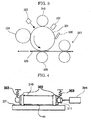
- tandem information forming apparatus There are two types of tandem information forming apparatus: (1) direct transfer type and (2) indirect transfer type.
- direct transfer type visible images formed on the photoconductor 1 are transferred sequentially by the transfer unit 2 to a recording medium S of which the surface is being transported so as to pass through the transfer position, which is facing each photoconductor 1 of multiple image forming elements as shown in FIG. 7 .
- indirect transfer type visible images on each photoconductor 1 of multiple image forming elements are temporarily transferred sequentially by the primary transfer unit 2 to the intermediate transfer member 4 and then all the images on the intermediate transfer member 4 are transferred together to the recording medium S by the secondary transfer unit 5 as shown in FIG. 8 .
- the indirect transfer type of the tandem image forming apparatus is particularly interested recently.
- this type of color image forming apparatus as shown in FIG. 8 , prepares for the next image forming by removing the residual toner on the photoconductor 1 by the photoconductor cleaning unit 8 to clean the surface of the photoconductor 1 after the primary transfer. It also prepares for the next image forming by removing the residual toner on the intermediate transfer member 4 by the intermediate transfer member cleaning unit 9 to clean the surface of the intermediate transfer member 4 after the secondary transfer.
- the toner image is transferred onto the recording medium, the recording medium having an image is passed between the nip to fix the image onto the recording medium or the image is transferred and also fixed simultaneously at the nip.
- the fixing step may be carried out for each toner at every transferring onto the recording medium or the all toners are overlapped and then fixed simultaneously.
- the electromagnetic induction-heating units may preferably be constructed from an induction coil accessible to the fixing member such as heating rollers, a shielding layer for the induction coil, and an insulative layer disposed to the shielding layer oppositely to the induction coil.
- the heating roller is preferably of magnetic material or heat pipes.
- the induction coil is disposed to surround the half-cylinder, of the heating roller at the side opposite to the site where the heating roller and the fixing member contact.
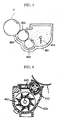
- FIG. 9 exemplarily shows a belt-type fixing unit or internal heating.
- the belt-type fixing unit 510 comprises a heating roller 511, a fixing roller 512, a fixing belt 513, and a pressure roller 514.
- the heating roller 520 comprises a hollow metal cylinder 521, an offset inhibition layer 522 coated on the surface of the metal cylinder 521, and a heating lamp 523 disposed in the metal cylinder 521.
- the pressure roller 530 comprises a metal cylinder 531, and an offset inhibition layer 532 coated on the surface of the metal cylinder 531.
- the metal cylinder 531 of the pressure roller 530 is hollow and equipped with a heating lamp 533 therein.
- the heating roller 566 comprises a magnetic metal member formed of iron, cobalt, nickel, or alloy thereof, in formed of hollow cylinder; for example, the outer diameter is 20 mm to 40 mm, and a thickness is 0.3 mm to 1.0 mm, thus the heating roller 320 has a configuration of low thermal capacity and rapid thermal conductivity.
- the fixing roller 520 has a metal core 521 on which a heat-insulative elastic layer 522, a heat-generating layer 523, and a release layer 524 are coated in this order
- the pressure roller 530 has a metal core 531 on which a heat-insulative elastic layer 532, a heat-generating layer 533, and a release layer 534 are coated in this order.
- the release layers 524 and 534 are formed of' tetrafluoroethylene perfluoroalkylvinylether (PFA).
- the electromagnetic induction heat sources 540 are disposed near the fixing roller 520 and the pressure roller 530 to heat the heat generating layers 523 and 533 by electromagnetic induction.
- the cleaning may be conducted without the cleaning unit in a cleaning-less manner
- the material of the cleaning rubber blades may be urethane robber, silicone rubber, fluorinated rubber, chloroprene rubber, and butadiene rubber, Among these, urethane rubber is preferable in particular.
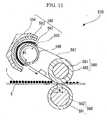
- FIG. 13 is an enlarged view that explains around the contacting site 615 between a cleaning blade 613 and the photoconductor.
- the cleaning blade 613 has a toner-blocking face 617 in a relation with the photoconductor drum 1.
- the toner-blocking face 617 broadens from the contacting portion 615 toward the upstream of the rotating direction of the photoconductor drum 1 to form an acute angle in the space S.
- a coating 618 is provided at the toner-blocking face 617, as shown in FIG. 13 , as a higher friction portion with higher friction coefficients.
- the coating 618 is formed of a material with a higher friction coefficient ⁇ than that of the cleaning blade 613.
- the higher friction material is exemplified by diamond-like carbon (DLC), but not limited to
- DLC diamond-like carbon
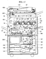
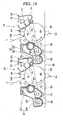
- FIG. 14 is a schematic view that exemplarily shows an image forming apparatus of cleaning-less type where its developing unit acts also as a cleaning unlit.
- Each piece of color information (black, yellow, magenta, and cyan) is transmitted to the image forming unit 18 (black image forming unit, yellow image forming unit, magenta image forming unit, or cyan image forming unit) of the tandem developing unit 120, and toner images of each color are formed in the image-forming units 18. As shown in FIG.
- the process cartridge contains a latent electrostatic image bearing member that is configured to bear a latent electrostatic image thereon, and a developing unit which is configured to develop the latent electrostatic image on the latent electrostatic image bearing member with a developer to form a visible image.
- the process cartridge further contains other units such as charging units, transfer units, cleaning units and discharging units as necessary.
- DSC210 differential scanning calorimeter
- a polyester binder resin as a sample is weighed on an aluminum pan, which is then heated to 200°C, thereafter the sample is cooled to 0°C at cool-down rate 10°C/min followed by heating up at a rate of 10°C/min.
- the glass transition temperature is determined at the temperature of the point where two lines intersect, i.e. between the extending line of the base line below the endothermal maximum peak temperature and the tangent line at the maximum gradient from the rising point to the peak point.
- tetrahydrofuran is flowed at 1 mL/min as an eluting solvent into an analytical column in a constant-temperature bath at 40°C to condition the column, followed by injecting 100 ⁇ L of the sample solution.
- the column is GMHLX+G3000HXL (by Tosoh Co.).
- the analytical curve is prepared using several types of monodisperse polystyrene as standard samples (2.63 ⁇ 10 3 , 2.06 ⁇ 10 4 , 1.02 ⁇ 10 5 , by Tosoh Co ; 2.10 ⁇ 10 3 , 7.00 ⁇ 10 3 , 5.04 ⁇ 10 4 , by JL Sciences Inc.).
- tall rosin to be purified is referred to as unpurified rosin
- rosin from which main distilling components having been removed is referred to as purified rosin
- Saturated SP value of acrylic acid-modified rosin prepared from unpurified rosin was measured as follows. 332 g (1 mole) of unpurified rosin (SP value: 77.0°C) and 72 g (1 mole) of acrylic acid were added into a flask of 1000 mL equipped with a fractionating column, a reflux condenser, and a trap, and the reactant was heated up from 160°C to 230°C over 8 hours. After checking that SP value represents no rise at 230°C, unreacted acrylic acid and volatile substances were distilled away under a reduced pressure of 5.3 kPa thereby to prepare an acrylic acid-modified rosin The SP value of the resulting acrylic acid-modified rosin, i.e. the saturated SP value of the acrylic acid-modified rosin prepared from the unpurified rosin was 110 1°C.
- the alcohol components other than glycerin, carboxylic acid components other than anhydrous trimellitic acid, and esterification catalysts shown in Table 2A were added into a four-necked 5L flask, equipped with a distillation tube, flowing 98°C warm water, mounted upward a condenser flowing water at room temperature, a nitrogen inlet, a water outlet, a stirrer, and a thermocouple, then the mixture was subjected to condensation polymerization at 160°C for 2 hours under nitrogen atmosphere, then the reactant was heated to 210°C over 6 hours, followed by allowing to react for 1 hour under 66 kPa.
- Polyester binder resin 1 100 parts Black toner master batch (TB-K1) 16 parts Charge control agent (E-84) *1) 1 part Ester wax *2) 5 parts *1) by Orient Chemical Industries, Ltd, *2) acid value: 5 mgKOH/g, weight average molecular weight: 1600
- a toner is filled into two open-cylindrical containers of 5 cm diameter and 2 cm high in a weight of 4 g respectively.
- One container is allowed to stand at temperature 40°C and relative humidity 60%, and another container is allowed to stand at temperature 55°C and relative humidity 60%, for 72 hours. After this period, the containers with a toner are shaken mildly, then the existence of toner agglomeration is visually observed and the storage stability is evaluated in accordance with the following criteria.
- the image quality is evaluated with respect to tone uniformity, background smear, image density, and haze of output images.
- the images are visually observed and evaluated into three steps below..
- a coating material of the composition shown below was dispersed for 10 minutes using a stirrer to prepare a coating liquid.
- the coating liquid was poured into a coating device where 5000 parts of a core material (Cu-Zn ferrite particles, weight average particle diameter: 35 ⁇ m) was coated with the coating liquid while forming a swirl flow by action of a rotatable bottom disc and stirring blades within a fluidized bed
- the resulting coated material was heated at 250°C for 2 hours in an electric furnace to prepare a carrier
- the resulting two-component developers 1 to 8 were filled into image forming apparatus B shown in FIG. 21 and images were formed, then temporal stability was evaluated as follows, and also lower-limit fixing temperature, image quality, and overall judgment were evaluated in the same manner as Examples A1 to A6 and Comparative Examples A1 and A2. The results are shown in Table 6A.
- Image forming apparatus B shown in FIG. 21 is a tandem image forming apparatus of indirect transfer type that employs non-contact charging, two-component developing, secondary transfer, blade cleaning, and external-heating roller fixing.
- a solid image is printed on 6000 paper (by Ricoh Co.) before and after running printing 100,000 sheets of image chart with 35% image area.
- the image quality is evaluated by comparing before and after the running printing in the same manner as Examples 1 to 6 and Comparative Examples 1 and 2
- Tables 5A and 6A demonstrate that the toners or two-component developers of Examples A1 to A12, comprising a polyester resin that is prepared by condensation polymerization between an alcohol component that contains an aliphatic polyvalent alcohol and a carboxylic acid component that contains (meth)acrylic acid-modified rosin as a binder resin of the toner, may exhibit excellent fixing ability and provide high quality images far from tone change with time, and with substantially no occurrences of abnormal images such as density-drop and background smear, compared with those of Comparative Examples A1 and A3 containing no (meth)acrylic acid-modified rosin.
- the image forming methods, according to the present invention employ toners that are excellent in low temperature fixing ability, hot offset resistance, and storage stability, and also generate less odor, therefore, can provide high quality images with superior fixing ability, far from tone change with time, and less likely to occur abnormal images such as density-drop and background smear, consequently, can be widely utilized for laser printers, direct digital printmakers, full color copiers of direct or indirect electrophotographic multi-color development, full color laser printers, full color facsimiles for regular paper, etc.
Landscapes
- Physics & Mathematics (AREA)
- General Physics & Mathematics (AREA)
- Spectroscopy & Molecular Physics (AREA)
- Chemical & Material Sciences (AREA)
- Chemical Kinetics & Catalysis (AREA)
- Developing Agents For Electrophotography (AREA)
Claims (17)
- Bilderzeugungsverfahren, umfassend:das Aufladen einer Oberfläche eines latenten elektrostatischen Bildträgerelements, das Belichten der aufgeladenen Oberfläche des latenten elektrostatischen Bildträgerelements, um ein latentes elektrostatisches Bild zu bilden, das Entwickeln des latenten elektrostatischen Bildes unter Verwendung eines Toners, um ein sichtbares Bild zu bilden, das Übertragen des sichtbaren Bildes auf ein Aufzeichnungsmedium, und das Fixieren des übertragenen Bildes auf dem Aufzeichnungsmedium,wobei der Toner ein Bindemittelharz und ein farbgebendes Mittel umfasst, das Bindemittelharz ein Polyesterharz umfasst, das hergestellt ist durch Kondensationspolymerisation zwischen einer Alkoholkomponente, die einen aliphatischen mehrwertigen Alkohol enthält, und einer Carbonsäurekomponente, die (Meth)acrylsäure-modifiziertes Kolophonium enthält, und wobei das (Meth)acrylsäure-modifizierte Kolophonium durch Modifizieren eines gereinigten Kolophoniums mit (Meth)acrylsäure hergestellt ist.
- Bilderzeugungsverfahren nach Anspruch 1, wobei das Bilderzeugungsverfahren mit einer Bilderzeugungsvorrichtung durchgeführt wird, wobei die Bilderzeugungsvorrichtung eine Ladeeinheit umfasst, und die Ladeeinheit das latente elektrostatische Bildträgerelement in kontaktloser Weise auflädt.
- Bilderzeugungsverfahren nach Anspruch 1, wobei das Bilderzeugungsverfahren mit einer Bilderzeugungsvorrichtung durchgeführt wird, wobei die Bilderzeugungsvorrichtung eine Ladeeinheit umfasst, und die Ladeeinheit das latente elektrostatische Bildträgerelement durch Kontakt damit auflädt.
- Bilderzeugungsverfahren nach irgendeinem der Ansprüche 1 bis 3, wobei das Bilderzeugungsverfahren mit einer Bilderzeugungsvorrichtung durchgeführt wird, wobei die Bilderzeugungsvorrichtung eine Entwicklereinheit umfasst, und die Entwicklereinheit eine darin angeordnete Magnetfeld-Erzeugungseinheit und ein drehbares einen Entwickler tragendes Element, das einen Zweikomponentenentwickler aus einem magnetischen Träger und einem Toner darauf trägt, umfasst.
- Bilderzeugungsverfahren nach irgendeinem der Ansprüche 1 bis 3, wobei das Bilderzeugungsverfahren mit einer Bilderzeugungsvorrichtung durchgeführt wird, wobei die Bilderzeugungsvorrichtung eine Entwicklereinheit umfasst, und die Entwicklereinheit ein einen Entwickler tragendes Element, zu dem ein Toner zugeführt wird, und ein Schichtdicke-Kontrollelement zur Bildung einer Toner-Dünnschicht auf der Oberfläche des den Entwickler tragenden Elements umfasst.
- Bilderzeugungsverfahren nach irgendeinem der Ansprüche 1 bis 5, wobei das Bilderzeugungsverfahren mit einer Bilderzeugungsvorrichtung durchgeführt wird, wobei die Bilderzeugungsvorrichtung eine Transfereinheit umfasst, und die Transfereinheit ein sichtbares Bild, das auf dem latenten elektrostatischen Bildträgerelement gebildet wird, auf ein Aufzeichnungsmedium überträgt.
- Bilderzeugungsverfahren nach irgendeinem der Ansprüche 1 bis 6, wobei das Bilderzeugungsverfahren mit einer Bilderzeugungsvorrichtung durchgeführt wird, wobei die Bilderzeugungsvorrichtung mehrere Bilderzeugungselemente umfasst, die jeweils ein latentes elektrostatisches Bildträgerelement, eine Ladeeinheit, eine Entwicklereinheit und eine Transfereinheit umfassen,
wobei die Transfereinheit Bilder, die auf dem latenten elektrostatischen Bildträgerelement gebildet werden, der Reihe nach auf ein Aufzeichnungsmedium überträgt, dessen Oberfläche sich durch die Transferstelle bewegt, während es dem latenten elektrostatischen Bildträgerelement gegenübersteht. - Bilderzeugungsverfahren nach irgendeinem der Ansprüche 1 bis 5, wobei das Bilderzeugungsverfahren mit einer Bilderzeugungsvorrichtung durchgeführt wird, wobei die Bilderzeugungsvorrichtung eine Transfereinheit umfasst, und die Transfereinheit ein Zwischentransferelement, auf das das sichtbare Bild, das auf dem latenten elektrostatischen Bildträgerelement gebildet wird, primär übertragen wird, und eine sekundäre Transfereinheit, die das sichtbare Bild, das auf dem Zwischentransferelement gebildet wird, auf das Aufzeichnungsmedium überträgt, umfasst.
- Bilderzeugungsverfahren nach irgendeinem der Ansprüche 1 bis 8, wobei das Bilderzeugungsverfahren mit einer Bilderzeugungsvorrichtung durchgeführt wird, wobei die Bilderzeugungsvorrichtung eine Reinigungseinheit umfasst, und die Reinigungseinheit eine Reinigungsrakel umfasst, die mit der Oberfläche des latenten elektrostatischen Bildträgerelements in Kontakt kommt.
- Bilderzeugungsverfahren nach irgendeinem der Ansprüche 1 bis 8, wobei das Bilderzeugungsverfahren mit einer Bilderzeugungsvorrichtung durchgeführt wird, wobei die Bilderzeugungsvorrichtung eine Entwicklereinheit umfasst, und die Entwicklereinheit ein Entwicklerträgerelement umfasst, das mit der Oberfläche des latenten elektrostatischen Bildträgerelements in Kontakt kommt, und
die Entwicklereinheit ein latentes elektrostatisches Bild, das auf der Oberfläche des latenten elektrostatischen Bildträgerelements gebildet wird, entwickelt und den restlichen Toner auf dem latenten elektrostatischen Bildträgerelement sammelt. - Bilderzeugungsverfahren nach irgendeinem der Ansprüche 1 bis 10, wobei das Bilderzeugungsverfahren mit einer Bilderzeugungsvorrichtung durchgeführt wird, wobei die Bilderzeugungsvorrichtung eine Fixiereinheit umfasst, und die Fixiereinheit eine Walze und/oder ein Band umfasst, und
die Fixiereinheit von der Seite, die sich von der in Kontakt mit dem Toner unterscheidet, erwärmt wird und das Bild, das auf dem Aufzeichnungsmedium übertragen wurde, durch Wärme und Druck fixiert. - Bilderzeugungsverfahren nach irgendeinem der Ansprüche 1 bis 10, wobei das Bilderzeugungsverfahren mit einer Bilderzeugungsvorrichtung durchgeführt wird, wobei die Bilderzeugungsvorrichtung eine Fixiereinheit umfasst, und die Fixiereinheit eine Walze und/oder ein Band umfasst, und
die Fixiereinheit von der Seite, die in Kontakt mit dem Toner ist, erwärmt wird und das Bild, das auf dem Aufzeichnungsmedium übertragen wurde, durch Wärme und Druck fixiert. - Bilderzeugungsverfahren nach irgendeinem der Ansprüche 1 bis 12, wobei der aliphatische mehrwertige Alkohol einen mit einer Kohlenstoffzahl von 2 bis 6 umfasst.
- Bilderzeugungsverfahren nach irgendeinem der Ansprüche 1 bis 13, wobei der Gehalt des (Meth)acrylsäure-modifizierten Kolophoniums in der Carbonsäure-Komponente 5 Massen-% bis 85 Massen-% beträgt.
- Bilderzeugungsverfahren nach irgendeinem der Ansprüche 1 bis 14, wobei die Alkoholkomponente einen drei- oder höherwertigen Alkohol umfasst, und/oder die Carbonsäure-Komponente eine drei- oder höherwertige Carbonsäure umfasst.
- Bilderzeugungsverfahren nach irgendeinem der Ansprüche 1 bis 15, wobei der Gehalt an niedermolekularen Komponenten mit einem Molekulargewicht von 500 oder weniger in dem Polyesterharz 12 Massen-% oder weniger beträgt.
- Bilderzeugungsverfahren nach irgendeinem der Ansprüche 1 bis 16, wobei die Kondensationspolymerisation in Gegenwart einer Titanverbindung und/oder einer Zinn (II)-Verbindung, die keine Sn-C-Bindung aufweist, durchgeführt wird.
Applications Claiming Priority (3)
| Application Number | Priority Date | Filing Date | Title |
|---|---|---|---|
| JP2006118087A JP4749928B2 (ja) | 2006-04-21 | 2006-04-21 | 画像形成装置、画像形成方法、及びプロセスカートリッジ |
| JP2006118026A JP4749924B2 (ja) | 2006-04-21 | 2006-04-21 | 画像形成装置、画像形成方法、及びプロセスカートリッジ |
| JP2006118103A JP4749929B2 (ja) | 2006-04-21 | 2006-04-21 | 画像形成装置、画像形成方法、及びプロセスカートリッジ |
Publications (2)
| Publication Number | Publication Date |
|---|---|
| EP1847883A1 EP1847883A1 (de) | 2007-10-24 |
| EP1847883B1 true EP1847883B1 (de) | 2012-12-26 |
Family
ID=38219519
Family Applications (1)
| Application Number | Title | Priority Date | Filing Date |
|---|---|---|---|
| EP07106584A Active EP1847883B1 (de) | 2006-04-21 | 2007-04-20 | Bilderzeugungsverfahren |
Country Status (2)
| Country | Link |
|---|---|
| US (1) | US7892718B2 (de) |
| EP (1) | EP1847883B1 (de) |
Families Citing this family (18)
| Publication number | Priority date | Publication date | Assignee | Title |
|---|---|---|---|---|
| US7862973B2 (en) * | 2006-11-22 | 2011-01-04 | Ricoh Company, Ltd. | Toner and developer, and image forming apparatus, image forming method and process cartridge |
| JP4749925B2 (ja) * | 2006-04-21 | 2011-08-17 | 株式会社リコー | 画像形成装置、画像形成方法、及びプロセスカートリッジ |
| EP2028551B1 (de) * | 2006-06-02 | 2014-07-23 | Kao Corporation | Toner fur die elektrofotografie |
| JP4668887B2 (ja) * | 2006-11-22 | 2011-04-13 | 株式会社リコー | トナー、並びにこれを用いた画像形成装置、画像形成方法、及びプロセスカートリッジ |
| JP5090057B2 (ja) * | 2007-05-11 | 2012-12-05 | 株式会社リコー | トナー、並びにこれを用いた画像形成装置及び画像形成方法 |
| US8114560B2 (en) * | 2007-05-11 | 2012-02-14 | Ricoh Company, Ltd. | Toner, image forming apparatus, image forming method, and process cartridge using the toner |
| JP5054443B2 (ja) * | 2007-06-20 | 2012-10-24 | 株式会社リコー | 画像形成装置、画像形成方法、及びプロセスカートリッジ |
| US20090067903A1 (en) * | 2007-09-10 | 2009-03-12 | Kabushiki Kaisha Toshiba | Coil unit for induction heating fixing device |
| US8329370B2 (en) * | 2007-10-19 | 2012-12-11 | Ricoh Company, Ltd. | Toner, image forming apparatus, image forming method, and process cartridge |
| US7901861B2 (en) * | 2007-12-04 | 2011-03-08 | Ricoh Company Limited | Electrophotographic image forming method |
| US8012659B2 (en) * | 2007-12-14 | 2011-09-06 | Ricoh Company Limited | Image forming apparatus, toner, and process cartridge |
| JP5473252B2 (ja) * | 2008-06-02 | 2014-04-16 | 株式会社リコー | トナー、現像剤、及び画像形成方法 |
| JP5369691B2 (ja) * | 2008-11-28 | 2013-12-18 | 株式会社リコー | トナー及び現像剤 |
| JP2010170004A (ja) * | 2009-01-26 | 2010-08-05 | Seiko Epson Corp | 画像形成装置および画像形成方法 |
| CN102356357B (zh) * | 2009-03-19 | 2015-04-22 | 三菱化学成像公司 | 包含生物树脂的生物调色剂、其制备方法以及用包含生物树脂的生物调色剂打印的方法 |
| JP5494922B2 (ja) | 2009-06-10 | 2014-05-21 | 株式会社リコー | トナー、現像剤、トナー入り容器、プロセスカートリッジ、画像形成方法及び画像形成装置 |
| JP5085699B2 (ja) * | 2010-08-27 | 2012-11-28 | シャープ株式会社 | 現像装置及びこれを備えた画像形成装置 |
| JP2014142406A (ja) * | 2013-01-22 | 2014-08-07 | Ricoh Co Ltd | 押圧部材、定着装置及び画像形成装置 |
Family Cites Families (34)
| Publication number | Priority date | Publication date | Assignee | Title |
|---|---|---|---|---|
| JPS5930542A (ja) * | 1982-07-23 | 1984-02-18 | Arakawa Chem Ind Co Ltd | 電子写真用トナ−組成物 |
| JPS59204848A (ja) * | 1983-05-09 | 1984-11-20 | Arakawa Chem Ind Co Ltd | 電子写真用トナ−組成物 |
| JPH083663B2 (ja) | 1986-11-10 | 1996-01-17 | 東洋インキ製造株式会社 | 低温定着性に優れた電子写真用トナ−組成物 |
| JP2516886B2 (ja) | 1987-06-16 | 1996-07-24 | キヤノン株式会社 | 像加熱装置 |
| JP2673959B2 (ja) | 1988-04-15 | 1997-11-05 | キヤノン株式会社 | 定着装置 |
| JP2698632B2 (ja) | 1988-11-08 | 1998-01-19 | 花王株式会社 | 電子写真用現像剤組成物 |
| JPH0470765A (ja) | 1990-07-11 | 1992-03-05 | Arakawa Chem Ind Co Ltd | 電子写真用トナー組成物 |
| JPH0782254B2 (ja) | 1991-04-04 | 1995-09-06 | 日本合成化学工業株式会社 | トナー用のバインダー樹脂 |
| JPH05341617A (ja) | 1992-06-12 | 1993-12-24 | Toshiba Corp | カラー画像形成装置 |
| JP3194396B2 (ja) | 1992-06-12 | 2001-07-30 | 株式会社リコー | 静電荷像現像用負帯電性トナー及びそれを用いた二成分系乾式現像剤 |
| JP3289051B2 (ja) | 1993-04-16 | 2002-06-04 | 株式会社リコー | 電子写真用トナー |
| JPH0822206A (ja) | 1994-07-08 | 1996-01-23 | Canon Inc | 加熱装置および画像形成装置 |
| DE69716266T2 (de) | 1996-07-03 | 2003-06-12 | British Telecomm | Sprachaktivitätsdetektor |
| JPH10307419A (ja) | 1997-05-06 | 1998-11-17 | Ricoh Co Ltd | 電子写真用トナーおよびその製造方法 |
| JP4867119B2 (ja) | 2001-09-27 | 2012-02-01 | 荒川化学工業株式会社 | ポリエステル樹脂、その製造法、印刷インキ用バインダーおよび印刷インキ |
| US7052815B2 (en) | 2002-05-24 | 2006-05-30 | Ricoh Company, Limited | Color toner for developing electrostatic images, toner container containing the color toner, and image forming method and apparatus using the color toner |
| US7541128B2 (en) | 2002-09-26 | 2009-06-02 | Ricoh Company Limited | Toner, developer including the toner, and method for fixing toner image |
| JP4812049B2 (ja) | 2002-11-06 | 2011-11-09 | 荒川化学工業株式会社 | ポリエステル樹脂、その製造法、印刷インキ用バインダーおよび印刷インキ |
| JP3773906B2 (ja) | 2002-12-20 | 2006-05-10 | 三菱レイヨン株式会社 | トナー用線状ポリエステル樹脂およびトナー |
| JP4030907B2 (ja) | 2003-03-19 | 2008-01-09 | 株式会社リコー | 静電荷像現像用トナー |
| JP4702590B2 (ja) | 2003-03-24 | 2011-06-15 | 星光Pmc株式会社 | 印刷インキ用樹脂及び該印刷インキ用樹脂を使用した印刷インキ |
| CN100395282C (zh) | 2003-07-14 | 2008-06-18 | 三洋化成工业株式会社 | 树脂颗粒及其制造方法 |
| CN100474129C (zh) | 2003-07-14 | 2009-04-01 | 株式会社理光 | 调色剂、显影剂、显影装置以及图像形成装置 |
| JP2005070276A (ja) * | 2003-08-22 | 2005-03-17 | Ricoh Co Ltd | 画像形成装置、プロセスカートリッジ及びこれらに用いるトナー |
| CN102314104B (zh) | 2003-09-18 | 2013-05-01 | 株式会社理光 | 调色剂、显影剂、容器、处理盒、图像形成装置及方法 |
| JP2005115029A (ja) | 2003-10-08 | 2005-04-28 | Ricoh Co Ltd | トナー及びその製造方法、並びに、現像剤、トナー入り容器、プロセスカートリッジ、画像形成装置及び画像形成方法 |
| JP4070702B2 (ja) | 2003-10-10 | 2008-04-02 | 株式会社リコー | 静電荷像現像用トナー、現像剤、画像形成方法および画像形成装置 |
| EP1530100B1 (de) | 2003-10-22 | 2009-02-11 | Ricoh Company, Ltd. | Bilderzeugungsverfahren |
| US7642032B2 (en) | 2003-10-22 | 2010-01-05 | Ricoh Company, Limited | Toner, developer, image forming apparatus and image forming method |
| CA2555338C (en) | 2004-02-03 | 2010-09-28 | Ricoh Company, Ltd. | Toner, developer, toner container, process cartridge, image forming apparatus, and image forming method |
| JP2005350597A (ja) | 2004-06-11 | 2005-12-22 | Mitsui Chemicals Inc | トナー用バインダー樹脂及び電子写真用トナー |
| US7932007B2 (en) | 2004-09-21 | 2011-04-26 | Ricoh Company, Ltd. | Toner and method for producing the same, and image-forming method using the same |
| US7550245B2 (en) | 2004-12-28 | 2009-06-23 | Ricoh Company, Ltd. | Toner and production method of the same, and image forming method |
| JP4668887B2 (ja) | 2006-11-22 | 2011-04-13 | 株式会社リコー | トナー、並びにこれを用いた画像形成装置、画像形成方法、及びプロセスカートリッジ |
-
2007
- 2007-04-20 EP EP07106584A patent/EP1847883B1/de active Active
- 2007-04-20 US US11/738,149 patent/US7892718B2/en active Active
Also Published As
| Publication number | Publication date |
|---|---|
| US20070248380A1 (en) | 2007-10-25 |
| EP1847883A1 (de) | 2007-10-24 |
| US7892718B2 (en) | 2011-02-22 |
Similar Documents
| Publication | Publication Date | Title |
|---|---|---|
| EP1847883B1 (de) | Bilderzeugungsverfahren | |
| EP1925983B1 (de) | Toner und Entwickler | |
| US8329370B2 (en) | Toner, image forming apparatus, image forming method, and process cartridge | |
| EP1990683B1 (de) | Toner, Bilderzeugungsvorrichtung, Bilderzeugungsverfahren und den Toner verwendende Prozesskartusche | |
| JP4749939B2 (ja) | 画像形成装置、画像形成方法、及びプロセスカートリッジ | |
| JP5054443B2 (ja) | 画像形成装置、画像形成方法、及びプロセスカートリッジ | |
| JP4749937B2 (ja) | 画像形成装置、画像形成方法、及びプロセスカートリッジ | |
| US8007974B2 (en) | Toner, image forming apparatus using the same, image forming method using the same, and process cartridge | |
| JP4749925B2 (ja) | 画像形成装置、画像形成方法、及びプロセスカートリッジ | |
| JP2008310280A (ja) | トナー、並びにこれを用いた画像形成装置、画像形成方法、及びプロセスカートリッジ | |
| JP4749938B2 (ja) | 画像形成装置、画像形成方法、及びプロセスカートリッジ | |
| JP4749940B2 (ja) | 画像形成装置、画像形成方法、及びプロセスカートリッジ | |
| JP4749929B2 (ja) | 画像形成装置、画像形成方法、及びプロセスカートリッジ | |
| JP2008310284A (ja) | トナー、並びにこれを用いた画像形成装置、画像形成方法、及びプロセスカートリッジ | |
| JP4749928B2 (ja) | 画像形成装置、画像形成方法、及びプロセスカートリッジ | |
| JP4909233B2 (ja) | 画像形成装置、画像形成方法、及びプロセスカートリッジ | |
| JP4749927B2 (ja) | 画像形成装置、画像形成方法、及びプロセスカートリッジ | |
| JP4749924B2 (ja) | 画像形成装置、画像形成方法、及びプロセスカートリッジ | |
| JP4749926B2 (ja) | 画像形成装置、画像形成方法、及びプロセスカートリッジ |
Legal Events
| Date | Code | Title | Description |
|---|---|---|---|
| PUAI | Public reference made under article 153(3) epc to a published international application that has entered the european phase |
Free format text: ORIGINAL CODE: 0009012 |
|
| AK | Designated contracting states |
Kind code of ref document: A1 Designated state(s): AT BE BG CH CY CZ DE DK EE ES FI FR GB GR HU IE IS IT LI LT LU LV MC MT NL PL PT RO SE SI SK TR |
|
| AX | Request for extension of the european patent |
Extension state: AL BA HR MK YU |
|
| 17P | Request for examination filed |
Effective date: 20080331 |
|
| 17Q | First examination report despatched |
Effective date: 20080527 |
|
| AKX | Designation fees paid |
Designated state(s): DE FR GB |
|
| REG | Reference to a national code |
Ref country code: DE Ref legal event code: R079 Ref document number: 602007027579 Country of ref document: DE Free format text: PREVIOUS MAIN CLASS: G03G0009087000 Ipc: G03G0015200000 |
|
| RIC1 | Information provided on ipc code assigned before grant |
Ipc: G03G 9/087 20060101ALI20120522BHEP Ipc: G03G 15/20 20060101AFI20120522BHEP |
|
| GRAP | Despatch of communication of intention to grant a patent |
Free format text: ORIGINAL CODE: EPIDOSNIGR1 |
|
| RIN1 | Information on inventor provided before grant (corrected) |
Inventor name: WATANABE, YOHICHIROH Inventor name: SHITARA, YASUTADA Inventor name: IWAMOTO, YASUAKI |
|
| GRAS | Grant fee paid |
Free format text: ORIGINAL CODE: EPIDOSNIGR3 |
|
| GRAA | (expected) grant |
Free format text: ORIGINAL CODE: 0009210 |
|
| AK | Designated contracting states |
Kind code of ref document: B1 Designated state(s): DE FR GB |
|
| REG | Reference to a national code |
Ref country code: GB Ref legal event code: FG4D |
|
| REG | Reference to a national code |
Ref country code: DE Ref legal event code: R096 Ref document number: 602007027579 Country of ref document: DE Effective date: 20130228 |
|
| PLBE | No opposition filed within time limit |
Free format text: ORIGINAL CODE: 0009261 |
|
| STAA | Information on the status of an ep patent application or granted ep patent |
Free format text: STATUS: NO OPPOSITION FILED WITHIN TIME LIMIT |
|
| 26N | No opposition filed |
Effective date: 20130927 |
|
| REG | Reference to a national code |
Ref country code: DE Ref legal event code: R097 Ref document number: 602007027579 Country of ref document: DE Effective date: 20130927 |
|
| REG | Reference to a national code |
Ref country code: FR Ref legal event code: PLFP Year of fee payment: 10 |
|
| REG | Reference to a national code |
Ref country code: FR Ref legal event code: PLFP Year of fee payment: 11 |
|
| REG | Reference to a national code |
Ref country code: FR Ref legal event code: PLFP Year of fee payment: 12 |
|
| P01 | Opt-out of the competence of the unified patent court (upc) registered |
Effective date: 20230522 |
|
| PGFP | Annual fee paid to national office [announced via postgrant information from national office to epo] |
Ref country code: FR Payment date: 20230420 Year of fee payment: 17 Ref country code: DE Payment date: 20230420 Year of fee payment: 17 |
|
| PGFP | Annual fee paid to national office [announced via postgrant information from national office to epo] |
Ref country code: GB Payment date: 20230419 Year of fee payment: 17 |