EP1846807B1 - Ventil, insbesondere proportional-druckbegrenzungsventil - Google Patents
Ventil, insbesondere proportional-druckbegrenzungsventil Download PDFInfo
- Publication number
- EP1846807B1 EP1846807B1 EP20060706391 EP06706391A EP1846807B1 EP 1846807 B1 EP1846807 B1 EP 1846807B1 EP 20060706391 EP20060706391 EP 20060706391 EP 06706391 A EP06706391 A EP 06706391A EP 1846807 B1 EP1846807 B1 EP 1846807B1
- Authority
- EP
- European Patent Office
- Prior art keywords
- valve
- fluid
- pressure
- control device
- valve according
- Prior art date
- Legal status (The legal status is an assumption and is not a legal conclusion. Google has not performed a legal analysis and makes no representation as to the accuracy of the status listed.)
- Expired - Lifetime
Links
Images

Classifications
-
- F—MECHANICAL ENGINEERING; LIGHTING; HEATING; WEAPONS; BLASTING
- F16—ENGINEERING ELEMENTS AND UNITS; GENERAL MEASURES FOR PRODUCING AND MAINTAINING EFFECTIVE FUNCTIONING OF MACHINES OR INSTALLATIONS; THERMAL INSULATION IN GENERAL
- F16H—GEARING
- F16H61/00—Control functions within control units of change-speed- or reversing-gearings for conveying rotary motion ; Control of exclusively fluid gearing, friction gearing, gearings with endless flexible members or other particular types of gearing
- F16H61/38—Control of exclusively fluid gearing
- F16H61/40—Control of exclusively fluid gearing hydrostatic
- F16H61/4043—Control of a bypass valve
-
- F—MECHANICAL ENGINEERING; LIGHTING; HEATING; WEAPONS; BLASTING
- F15—FLUID-PRESSURE ACTUATORS; HYDRAULICS OR PNEUMATICS IN GENERAL
- F15B—SYSTEMS ACTING BY MEANS OF FLUIDS IN GENERAL; FLUID-PRESSURE ACTUATORS, e.g. SERVOMOTORS; DETAILS OF FLUID-PRESSURE SYSTEMS, NOT OTHERWISE PROVIDED FOR
- F15B13/00—Details of servomotor systems ; Valves for servomotor systems
- F15B13/02—Fluid distribution or supply devices characterised by their adaptation to the control of servomotors
- F15B13/04—Fluid distribution or supply devices characterised by their adaptation to the control of servomotors for use with a single servomotor
- F15B13/044—Fluid distribution or supply devices characterised by their adaptation to the control of servomotors for use with a single servomotor operated by electrically-controlled means, e.g. solenoids, torque-motors
-
- F—MECHANICAL ENGINEERING; LIGHTING; HEATING; WEAPONS; BLASTING
- F15—FLUID-PRESSURE ACTUATORS; HYDRAULICS OR PNEUMATICS IN GENERAL
- F15B—SYSTEMS ACTING BY MEANS OF FLUIDS IN GENERAL; FLUID-PRESSURE ACTUATORS, e.g. SERVOMOTORS; DETAILS OF FLUID-PRESSURE SYSTEMS, NOT OTHERWISE PROVIDED FOR
- F15B13/00—Details of servomotor systems ; Valves for servomotor systems
- F15B13/02—Fluid distribution or supply devices characterised by their adaptation to the control of servomotors
- F15B13/024—Pressure relief valves
-
- F—MECHANICAL ENGINEERING; LIGHTING; HEATING; WEAPONS; BLASTING
- F15—FLUID-PRESSURE ACTUATORS; HYDRAULICS OR PNEUMATICS IN GENERAL
- F15B—SYSTEMS ACTING BY MEANS OF FLUIDS IN GENERAL; FLUID-PRESSURE ACTUATORS, e.g. SERVOMOTORS; DETAILS OF FLUID-PRESSURE SYSTEMS, NOT OTHERWISE PROVIDED FOR
- F15B13/00—Details of servomotor systems ; Valves for servomotor systems
- F15B13/02—Fluid distribution or supply devices characterised by their adaptation to the control of servomotors
- F15B13/04—Fluid distribution or supply devices characterised by their adaptation to the control of servomotors for use with a single servomotor
- F15B13/042—Fluid distribution or supply devices characterised by their adaptation to the control of servomotors for use with a single servomotor operated by fluid pressure
- F15B13/043—Fluid distribution or supply devices characterised by their adaptation to the control of servomotors for use with a single servomotor operated by fluid pressure with electrically-controlled pilot valves
- F15B13/0433—Fluid distribution or supply devices characterised by their adaptation to the control of servomotors for use with a single servomotor operated by fluid pressure with electrically-controlled pilot valves the pilot valves being pressure control valves
-
- F—MECHANICAL ENGINEERING; LIGHTING; HEATING; WEAPONS; BLASTING
- F16—ENGINEERING ELEMENTS AND UNITS; GENERAL MEASURES FOR PRODUCING AND MAINTAINING EFFECTIVE FUNCTIONING OF MACHINES OR INSTALLATIONS; THERMAL INSULATION IN GENERAL
- F16H—GEARING
- F16H61/00—Control functions within control units of change-speed- or reversing-gearings for conveying rotary motion ; Control of exclusively fluid gearing, friction gearing, gearings with endless flexible members or other particular types of gearing
- F16H61/38—Control of exclusively fluid gearing
- F16H61/40—Control of exclusively fluid gearing hydrostatic
- F16H61/4148—Open loop circuits
-
- F—MECHANICAL ENGINEERING; LIGHTING; HEATING; WEAPONS; BLASTING
- F16—ENGINEERING ELEMENTS AND UNITS; GENERAL MEASURES FOR PRODUCING AND MAINTAINING EFFECTIVE FUNCTIONING OF MACHINES OR INSTALLATIONS; THERMAL INSULATION IN GENERAL
- F16K—VALVES; TAPS; COCKS; ACTUATING-FLOATS; DEVICES FOR VENTING OR AERATING
- F16K17/00—Safety valves; Equalising valves, e.g. pressure relief valves
- F16K17/02—Safety valves; Equalising valves, e.g. pressure relief valves opening on surplus pressure on one side; closing on insufficient pressure on one side
- F16K17/04—Safety valves; Equalising valves, e.g. pressure relief valves opening on surplus pressure on one side; closing on insufficient pressure on one side spring-loaded
- F16K17/0473—Multiple-way safety valves
-
- F—MECHANICAL ENGINEERING; LIGHTING; HEATING; WEAPONS; BLASTING
- F16—ENGINEERING ELEMENTS AND UNITS; GENERAL MEASURES FOR PRODUCING AND MAINTAINING EFFECTIVE FUNCTIONING OF MACHINES OR INSTALLATIONS; THERMAL INSULATION IN GENERAL
- F16K—VALVES; TAPS; COCKS; ACTUATING-FLOATS; DEVICES FOR VENTING OR AERATING
- F16K17/00—Safety valves; Equalising valves, e.g. pressure relief valves
- F16K17/02—Safety valves; Equalising valves, e.g. pressure relief valves opening on surplus pressure on one side; closing on insufficient pressure on one side
- F16K17/04—Safety valves; Equalising valves, e.g. pressure relief valves opening on surplus pressure on one side; closing on insufficient pressure on one side spring-loaded
- F16K17/10—Safety valves; Equalising valves, e.g. pressure relief valves opening on surplus pressure on one side; closing on insufficient pressure on one side spring-loaded with auxiliary valve for fluid operation of the main valve
- F16K17/105—Safety valves; Equalising valves, e.g. pressure relief valves opening on surplus pressure on one side; closing on insufficient pressure on one side spring-loaded with auxiliary valve for fluid operation of the main valve using choking or throttling means to control the fluid operation of the main valve
-
- F—MECHANICAL ENGINEERING; LIGHTING; HEATING; WEAPONS; BLASTING
- F16—ENGINEERING ELEMENTS AND UNITS; GENERAL MEASURES FOR PRODUCING AND MAINTAINING EFFECTIVE FUNCTIONING OF MACHINES OR INSTALLATIONS; THERMAL INSULATION IN GENERAL
- F16K—VALVES; TAPS; COCKS; ACTUATING-FLOATS; DEVICES FOR VENTING OR AERATING
- F16K17/00—Safety valves; Equalising valves, e.g. pressure relief valves
- F16K17/20—Excess-flow valves
- F16K17/22—Excess-flow valves actuated by the difference of pressure between two places in the flow line
-
- G—PHYSICS
- G05—CONTROLLING; REGULATING
- G05D—SYSTEMS FOR CONTROLLING OR REGULATING NON-ELECTRIC VARIABLES
- G05D16/00—Control of fluid pressure
- G05D16/04—Control of fluid pressure without auxiliary power
- G05D16/10—Control of fluid pressure without auxiliary power the sensing element being a piston or plunger
- G05D16/101—Control of fluid pressure without auxiliary power the sensing element being a piston or plunger the controller being arranged as a multiple-way valve
-
- G—PHYSICS
- G05—CONTROLLING; REGULATING
- G05D—SYSTEMS FOR CONTROLLING OR REGULATING NON-ELECTRIC VARIABLES
- G05D16/00—Control of fluid pressure
- G05D16/14—Control of fluid pressure with auxiliary non-electric power
- G05D16/16—Control of fluid pressure with auxiliary non-electric power derived from the controlled fluid
- G05D16/166—Control of fluid pressure with auxiliary non-electric power derived from the controlled fluid using pistons within the main valve
-
- G—PHYSICS
- G05—CONTROLLING; REGULATING
- G05D—SYSTEMS FOR CONTROLLING OR REGULATING NON-ELECTRIC VARIABLES
- G05D16/00—Control of fluid pressure
- G05D16/20—Control of fluid pressure characterised by the use of electric means
- G05D16/2006—Control of fluid pressure characterised by the use of electric means with direct action of electric energy on controlling means
- G05D16/2013—Control of fluid pressure characterised by the use of electric means with direct action of electric energy on controlling means using throttling means as controlling means
- G05D16/2024—Control of fluid pressure characterised by the use of electric means with direct action of electric energy on controlling means using throttling means as controlling means the throttling means being a multiple-way valve
-
- G—PHYSICS
- G05—CONTROLLING; REGULATING
- G05D—SYSTEMS FOR CONTROLLING OR REGULATING NON-ELECTRIC VARIABLES
- G05D16/00—Control of fluid pressure
- G05D16/20—Control of fluid pressure characterised by the use of electric means
- G05D16/2093—Control of fluid pressure characterised by the use of electric means with combination of electric and non-electric auxiliary power
- G05D16/2097—Control of fluid pressure characterised by the use of electric means with combination of electric and non-electric auxiliary power using pistons within the main valve
-
- Y—GENERAL TAGGING OF NEW TECHNOLOGICAL DEVELOPMENTS; GENERAL TAGGING OF CROSS-SECTIONAL TECHNOLOGIES SPANNING OVER SEVERAL SECTIONS OF THE IPC; TECHNICAL SUBJECTS COVERED BY FORMER USPC CROSS-REFERENCE ART COLLECTIONS [XRACs] AND DIGESTS
- Y10—TECHNICAL SUBJECTS COVERED BY FORMER USPC
- Y10T—TECHNICAL SUBJECTS COVERED BY FORMER US CLASSIFICATION
- Y10T137/00—Fluid handling
- Y10T137/7722—Line condition change responsive valves
- Y10T137/7771—Bi-directional flow valves
-
- Y—GENERAL TAGGING OF NEW TECHNOLOGICAL DEVELOPMENTS; GENERAL TAGGING OF CROSS-SECTIONAL TECHNOLOGIES SPANNING OVER SEVERAL SECTIONS OF THE IPC; TECHNICAL SUBJECTS COVERED BY FORMER USPC CROSS-REFERENCE ART COLLECTIONS [XRACs] AND DIGESTS
- Y10—TECHNICAL SUBJECTS COVERED BY FORMER USPC
- Y10T—TECHNICAL SUBJECTS COVERED BY FORMER US CLASSIFICATION
- Y10T137/00—Fluid handling
- Y10T137/8593—Systems
- Y10T137/86493—Multi-way valve unit
- Y10T137/86574—Supply and exhaust
- Y10T137/86582—Pilot-actuated
- Y10T137/86614—Electric
-
- Y—GENERAL TAGGING OF NEW TECHNOLOGICAL DEVELOPMENTS; GENERAL TAGGING OF CROSS-SECTIONAL TECHNOLOGIES SPANNING OVER SEVERAL SECTIONS OF THE IPC; TECHNICAL SUBJECTS COVERED BY FORMER USPC CROSS-REFERENCE ART COLLECTIONS [XRACs] AND DIGESTS
- Y10—TECHNICAL SUBJECTS COVERED BY FORMER USPC
- Y10T—TECHNICAL SUBJECTS COVERED BY FORMER US CLASSIFICATION
- Y10T137/00—Fluid handling
- Y10T137/8593—Systems
- Y10T137/86493—Multi-way valve unit
- Y10T137/86574—Supply and exhaust
- Y10T137/8667—Reciprocating valve
- Y10T137/86694—Piston valve
- Y10T137/86702—With internal flow passage
-
- Y—GENERAL TAGGING OF NEW TECHNOLOGICAL DEVELOPMENTS; GENERAL TAGGING OF CROSS-SECTIONAL TECHNOLOGIES SPANNING OVER SEVERAL SECTIONS OF THE IPC; TECHNICAL SUBJECTS COVERED BY FORMER USPC CROSS-REFERENCE ART COLLECTIONS [XRACs] AND DIGESTS
- Y10—TECHNICAL SUBJECTS COVERED BY FORMER USPC
- Y10T—TECHNICAL SUBJECTS COVERED BY FORMER US CLASSIFICATION
- Y10T137/00—Fluid handling
- Y10T137/8593—Systems
- Y10T137/87917—Flow path with serial valves and/or closures
Definitions
- the invention relates to a valve, in particular proportional pressure relief valve, with a valve housing having at least three fluid connections, wherein the valve is connectable to a hydraulic drive system with a predeterminable consumer pressure.
- the proportional pressure control valves can be directly controlled spool valves in three-way design, ie with pressure relief on the output side. They are used, inter alia, in oil-hydraulic systems for controlling clutches in manual transmissions for selectively influencing pressure build-up and pressure reduction, for remote pressure adjustment, but also used for the control of pressure gradients and for pilot control of hydraulic valves and logic elements.
- the present invention seeks to provide a valve, in particular a proportional pressure relief valve, which has good stability even with the use of low-viscosity fluid media and reduce the component variety especially for use in safety-related areas including hydraulic traction drives helps.
- a valve having the features of claim 1 in its entirety.
- the applied consumer pressure acts on a fluid connection at least such on the valve piston, that depending on the upcoming consumer pressure and the actuating force of the control device, a fluid flow between the other two fluid connections in both directions within the valve housing is possible a valve is created that can perform safe valve switching functions even with low-viscosity fluid media and the susceptibility to disturbances is reduced.
- the shock valves, preload valves and directional control valves used hitherto can be replaced by a basic valve, wherein substantially the same switching and operating functions can then be implemented with only one valve according to the invention , This reduces the manufacturing and maintenance costs and since only one valve is to be mastered within the travel drive, overall the operational reliability is increased.
- the Fig.1 shows in the form of a circuit diagram parts of a hydraulic drive for a scissor lift not shown. These vehicles regularly have two axles, a rear-wheel drive being regularly implemented and the front axle can be controlled separately to realize a shiftable four-wheel drive, the drives being designed essentially the same for both axles.
- a hydraulic motor 10 which is driven in response to the switching position of a 4/3-way valve 12 in both directions of rotation for a forward or reverse operation and to realize a braking function.
- the 4/3-way valve 12 is as shown in the Fig.1 shown in the neutral position and the other input side connected to a hydraulic pump 14 and to a tank 16.
- the supply line of the hydraulic pump 14 is secured by a conventional pressure relief valve 18.
- a conventional pressure relief valve 18 To the respective input sides of the hydraulic motor 10 extend two parallel supply lines 20 and between the two supply lines 20 are arranged in parallel valves different valves, such as a release or circulation valve 22, two bias valves 24, each of which a pressure relief valve 26 is assigned, and two other pressure relief valves 28 as so-called shock valves.
- two secondary lines 30 In the area of the connection points of the in the direction of the Fig.1 seen to uppermost shock valve 28 in the two supply lines 20 are opposite two secondary lines 30 connected, the return via check valves to the tank 16 back.
- the pertinent non-return valves serve as suction valves to prevent cavitation.
- the known solution thus has two shock valves 28, two bias valves 24 with pressure relief valves 26 and a circulation valve 22, wherein the two bias valves 24 and the circulation valve 22 are formed in the form of 2/2-way valves.
- the pertinent inactive axle can be activated in support of the braking process.
- the circulation valve 22 is locked and in response to the braking direction, the further 2/2-way valve 24 is switched as a biasing valve, which thus releases a fluid-carrying path via its associated additional pressure relief valve 26. Since for a pertinent braking option in both opposite directions of travel Arrangement, as in the Fig.1 shown, must be present twice, resulting in a biasing or braking function thus twice the number of pressure relief valves 26 together with the 2/2-way valves 24th
- Fig.2 with the valve according to the invention are the same building components, as in the Fig.1 , also represented by the same reference numerals.
- the variety of shown individual valves after the solution after the Fig.1 is at the circuit diagram after the Fig.2 replaced by a valve according to the invention, which cooperates with a shuttle valve 32 as a further valve, wherein the three fluid ports 1, 2 and 3 are indicated and the control device of the valve is denoted by 4 '.
- the valve has a further fourth fluid connection, which is connected via the connecting line 34 to the tank 16 and serves for the pressure-free discharge of the pilot oil.
- Said valve arrangement with shuttle valve 32 is connected via connection points 36 between the two supply lines 20.
- valve housing 38 in the manner of a Einschraubpatrone.
- a fluid port 1 At the free end face of the valve housing 38 of a fluid port 1 is arranged and along the outer periphery of the valve housing 38 pass through in the radial direction, the other fluid ports 2, 3 and 4, the pertinent valve housing 38.
- the individual fluid ports 1, 2, 3 and 4 are correspondingly fluid-tightly separated from one another on the outer circumference of the valve housing 38 arranged seals.
- the shuttle valve 32 connected with its input sides to the fluid ports 1, 2 and 3 and to the connection points 36, which according to the illustration of the Fig.2 into the supply lines 20 open (in Figure 3 not shown).
- the valve housing 38 is, as shown, formed in the manner of Einschraubpatrone and can be screwed in such a way not shown in a connection block of the traction drive with its overall hydraulic system.
- the fluid port 1 opposite end of the valve housing 38 is provided with a control device 40 which formed in the manner of a magnetic system having a magnet armature 42 which can be energized by means of a coil (not shown in detail) within a pole tube 44 back and forth and thereby acting on an actuating rod 46 for driving a closing member 48 in the form of a closing cone.
- Lock member 48 and actuating rod 46 are separated from each other via a compression spring 50 as energy storage.
- Both the closing part 48 and the compression spring 50 and the front, the armature 42 remote end of the actuating rod 46 are guided in a fluid chamber 52 which is fluidly connected via the fluid connection 4 with the connecting line 34 after the Fig.2 , which opens with its free end in the tank 16.
- a valve piston 56 is guided, wherein the valve piston 56 forms a kind of main stage and the component 58 represents the pilot seat of the valve in the manner of a preliminary stage.
- the valve piston 56 defines with its one end face another fluid chamber 60 in which as a further energy storage a compression spring 62 is guided, which in a hollow cylindrical recess in the valve piston 56 engages.
- the valve piston 56 is further provided on the outer peripheral side with a radial recess 64 whose axial length is seen in the longitudinal direction of the valve dimensioned such that in predetermined switching or Verschiebestel settings of the valve piston 56 at least partially released a fluid-carrying path between the fluid ports 2 and 3 and again, like in the Figure 3 is shown, lockable.
- Both the valve piston 56 and the pilot seat 58 have longitudinal fluid channels 66,68 in the longitudinal direction, which in the direction of the Figure 3 seen at their right end each have a shutter 70 which throttle the fluid flow, which is present at the fluid port 1.
- Proportional valve shown can be flowed through in both directions, ie from the fluid port 2 to the fluid port 3 or vice versa from fluid port 3 to fluid port 2.
- the direction of the flow is determined inter alia, where in each case the highest consumer pressure in the supply lines 20 is present.
- the pertinent consumer pressure is reported by the shuttle valve 32 via a reporting line 72 to the fluid port 1 of the proportional valve. If the closing pressure which can be set by the magnet system of the control device 4 'is exceeded by the consumer pressure prevailing at the fluid connection 1 lifts the closing part 48 from the pilot seat 58 as a precursor, the pilot control opens and the valve piston 56 designed as a main stage moves against the force of the energy store in the form the compression spring 62 to the left.
- the fluid-conducting connection is opened from fluid port 2 to fluid port 3 and fluid (oil) can flow from the higher to the lower pressure level.
- the proportional valve fulfills the requirement for a non-pressurized oil circulation of an axle (axle in freewheel), for what hitherto an additional 2/2-way valve 22 (see. Fig.1 ) was necessary according to the prior art.
- valve solution according to the invention In a teilbestomten setting of the magnet system and thus partial activation of the armature 42 is realized with the valve solution according to the invention, the function of the bias described in which the hydraulic motor 10 is decelerated over a defined pressure, with the solution according to the invention via the magnetic force of the magnet system, the braking effect proportional can be adjusted.
- the pertinent valve function then replaces the previous combination of pressure relief valve 26 with 2/2-way valve 24 as a total bias system (cf. Fig.1 ).
- the proportional valve according to the invention fulfills the function of the previously known shock valves 28 as independent pressure relief valves.
- Another advantage of the solution according to the invention is that the reference of the proportional valve can be placed against the pressure in the tank 16, so that the pressures on the discharge side can no longer add up to the set pressure.
- the magnetic system has been replaced as a control device 4 'by a mechanical presetting, with a spindle 74 and a force spring 76, the closing pressure for the Locking part 48 can be specified by hand.
- the valve is designed as a double-acting pilot-operated shock valve with tank reference via the connecting line 34, wherein the double action based on the decoupling of the control terminal 1 of the load terminals 3 and 4.
- the pertinent valve variant is both defined (black / white - switching behavior) and proportionally controllable.
- the proportional drive according to the invention is used in the described hydraulic vehicle drive, a significant reduction in the number of valves required is possible and, overall, the installation space for the valve solution is reduced. Since the proportional valve according to the invention can be flowed through in both directions, so far, the double number of valves according to the known solution after the falls Fig.1 path. Based on the consideration that no two functions have to run simultaneously, one can turn on the alternative circuit of the proportional valve according to a hydraulic switching solution according to the Fig.2 fall back and thus save the large number of valves, which in total helps reduce the manufacturing and maintenance costs. However, the proportional valve according to the invention does not need to be limited to the use of vehicle drives, but can also be used in other hydraulic circuits especially due to its stable switching behavior, in particular where emphasis is placed on increased safety requirements.
Landscapes
- Engineering & Computer Science (AREA)
- General Engineering & Computer Science (AREA)
- Physics & Mathematics (AREA)
- Fluid Mechanics (AREA)
- Mechanical Engineering (AREA)
- General Physics & Mathematics (AREA)
- Automation & Control Theory (AREA)
- Power Engineering (AREA)
- Fluid-Driven Valves (AREA)
- Fluid-Pressure Circuits (AREA)
- Safety Valves (AREA)
Description
- Die Erfindung betrifft ein Ventil, insbesondere Proportional-Druckbegrenzungsventil, mit einem Ventilgehäuse mit mindestens drei Fluidanschlüssen, wobei das Ventil an ein hydraulisches Antriebssystem mit einem vorgebbaren Verbraucherdruck anschließbar ist.
- Bekannt sind Proportional-Druckregelventile (
US-A-4 316 599 ), die unter anderem Steuerventile für ölhydraulische Anlagen bilden, die bei veränderlichem Eingangsdruck im wesentlichen einen konstanten Ausgangsdruck liefern. Der zu steuernde Ausgangsdruck wird durch das Stromsignal vorgegeben, das von einer entsprechenden Ansteuerelektronik geliefert wird und auf einen Betätigungsmagneten als Magnetsystem wirkt. Der Betätigungsmagnet kann als druckdichter Öl-Badmagnet ausgeführt sein und weist eine lange Lebensdauer auf. - Dahingehende Proportional-Druckregelventile können direkt gesteuerte Kolbenschieberventile in Drei/Wege-Ausführung sein, d.h. mit ausgangsseitiger Druckabsicherung. Sie werden unter anderem in ölhydraulischen Anlagen zur Steuerung von Kupplungen in Schaltgetrieben zur gezielten Beeinflussung von Druckaufbau und Druckabbau, zur Druckferneinstellung, aber auch zur Steuerung von Druckverläufen und zur Vorsteuerung von Hydroventilen und Logikelementen eingesetzt.
- Dahingehende herkömmliche Proportional-Druckregelventile weisen insbesondere bei dünnflüssigen Fluidmedien eine schlechte Stabilität auf, d.h. sie beginnen zu "schwingen", was insbesondere dann schädlich ist, wenn die bekannten Ventile Sonderfunktionen erfüllen sollen, beispielsweise in Kraftfahrzeug-Servolenkungen, hydraulischen Fahrantrieben sowie sonstigen sicherheitstechnisch relevanten Bereichen. Es hat sich allgemein gezeigt, dass bei der Anwendung von Druckregelventilen die Anfälligkeit für Störgrößen im Eigenfrequenzbereich des Ventils liegt, wobei die auftretenden Instabilitäten bis zum Funktionsausfall des Ventils und der zugehörigen Anlagenteile einer Hydroanlage führen können.
- Im Stand der Technik sind ferner mehrachsige hydraulische Fahrantriebe für Hubarbeitsbühnen bekannt, die regelmäßig einen Heckantrieb aufweisen sowie einen zuschaltbaren Allradantrieb. Um einen funktionssicheren Betrieb zu gewährleisten mit Antrieb nur einer Achse und Freilauf der anderen Achse sowie Durchführen von Bremsvorgängen mit schlagartigem Abstoppen, ist bei der bekannten Lösung eine Vielzahl von Ventilkomponenten notwendig, wie zwei sog. Schockventile, zwei Vorspannventilkombinationen, bestehend aus je einem Druckbegrenzungsventil und einem 2/2-Wegeventil, und ein 2/2-Wegeventil als Umlaufventil. Der dahingehende Funktionsaufbau ist zwar sicher im Betrieb, aber bereits aufgrund der Vielzahl an Ventilen ist mit deren Ausfall im Betrieb zu rechnen, was die Wartungsintervalle verkürzt. Auch benötigt die bekannte Lösung viel Bauraum und ist aufgrund der Teilevielzahl teuer in der Herstellung.
- Ausgehend von diesem Stand der Technik liegt der Erfindung die Aufgabe zugrunde, ein Ventil, insbesondere ein Proportional-Druckbegrenzungsventil zu schaffen, das auch bei Einsatz von dünnflüssigen Fluidmedien eine gute Stabilität aufweist und das insbesondere bei einem Einsatz in sicherheitsrelevanten Bereichen einschließlich hydraulischen Fahrantrieben die Komponentenvielzahl reduzieren hilft. Eine dahingehende Aufgabe löst ein Ventil mit den Merkmalen des Patentanspruches 1 in seiner Gesamtheit.
- Dadurch, dass gemäß dem kennzeichnenden Teil des Patentanspruches 1 der anstehende Verbraucherdruck an einem Fluidanschluß zumindest derart auf den Ventilkolben einwirkt, dass abhängig vom anstehenden Verbraucherdruck und von der Betätigungskraft der Steuereinrichtung eine Fluiddurchströmung zwischen den beiden anderen Fluidanschlüssen in beiden Richtungen innerhalb des Ventilgehäuses möglich ist, ist ein Ventil geschaffen, das auch bei dünnflüssigen Fluidmedien sichere Ventilschaltfunktionen ausüben kann und die Anfälligkeit gegenüber Störgrößen reduziert ist. Sofern das Ventil innerhalb gesamthydraulischer Anlagen, wie hydraulischen Fahrantrieben, Anwendung findet, können die bisher zum Einsatz kommenden Schockventile, Vorspannventile und Wegeventile durch ein Grundventil ersetzt werden, wobei im wesentlichen die gleichen Schalt- und Betriebsfunktionen dann mit nur einem Ventil gemäß der Erfindung realisierbar sind. Dies reduziert die Herstell- und die Wartungskosten und da innerhalb des Fahrantriebes nur ein Ventil zu beherrschen ist, ist insgesamt die Betriebsfunktionssicherheit erhöht.
- Weitere vorteilhafte Ausführungsformen des erfindungsgemäßen Ventils sind Gegenstand der sonstigen Unteransprüche.
- Im folgenden wird das erfindungsgemäße Ventil, insbesondere Proportional-Druckbegrenzungsventil, anhand verschiedener Ausführungsbeispiele, nach der Zeichnung näher erläutert. Dabei zeigen in prinzipieller und nicht maßstäblicher Darstellung die
- Fig. 1
- in der Art eines hydraulischen Schaltplanes, Teile einer hy- draulischen Hubarbeitsbühne nach dem Stand der Technik;
- Fig.2
- eine der
Fig.1 entsprechende Schaltdarstellung, jedoch bezo- gen auf die erfindungsgemäße Lösung; - Fig.3 bis 5
- im Längsschnitt verschiedene Ausführungsformen des erfin- dungsgemäßen Ventils, wobei in der
Fig.3 der näheren Erläu- terung wegen noch das Wechselventil nach derFig.2 mit ein- gezeichnet ist. - Die
Fig.1 zeigt in der Art eines Schaltplanes Teile eines hydraulischen Fahrantriebes für eine nicht näher dargestellte Scherenhubarbeitsbühne. Dahingehende Fahrzeuge weisen regelmäßig zwei Achsen auf, wobei regelmäßig ein Heckantrieb realisiert ist und die Vorderachse ist zur Realisierung eines zuschaltbaren Allradantriebes getrennt ansteuerbar, wobei die Antriebe für beide Achsen im wesentlichen gleich konzipiert sind. In derFig.1 zum Stand der Technik ist als Antriebseinrichtung für eine nicht näher dargestellte Fahrzeugachse eines dahingehenden Fahrzeuges ein Hydromotor 10 dargestellt, der in Abhängigkeit der Schaltstellung eines 4/3-WegeVentils 12 in beiden Drehrichtungen antreibbar ist für einen Vorwärts-oder Rückwärtsbetrieb sowie zur Realisierung einer Bremsfunktion. Das 4/3-Wege-Ventil 12 ist gemäß der Darstellung nach derFig.1 in der Neutralstellung gezeigt und im übrigen eingangsseitig an eine Hydropumpe 14 angeschlossen sowie an einen Tank 16. - Die Versorgungsleitung der Hydropumpe 14 ist über ein übliches Druckbegrenzungsventil 18 abgesichert. Zu den jeweiligen Eingangsseiten des Hydromotors 10 verlaufen zwei parallel verlaufende Versorgungsleitungen 20 und zwischen die beiden Versorgungsleitungen 20 sind im Parallelschluß verschiedene Ventile angeordnet, wie ein Freischalt- oder Umlaufventil 22, zwei Vorspannventile 24, denen jeweils ein Druckbegrenzungsventil 26 zugeordnet ist, sowie zwei weitere Druckbegrenzungsventile 28 als sog. Schockventile. Im Bereich der Anschlußstellen des in Blickrichtung auf die
Fig.1 gesehen zuoberst angeordneten Schockventils 28 in die beiden Versorgungsleitungen 20 sind gegenüberliegend zwei Nebenleitungen 30 angeschlossen, die über Rückschlagventile abgesichert zum Tank 16 zurückführen. Die dahingehenden Rückschlagventile dienen als Nachsaugventile zur Vermeidung von Kavitation. Insgesamt weist die bekannte Lösung also zwei Schockventile 28, zwei Vorspannventile 24 mit Druckbegrenzungsventilen 26 sowie ein Umlaufventil 22 auf, wobei die beiden Vorspannventile 24 und das Umlaufventil 22 in Form von 2/2-Wege-Ventilen ausgebildet sind. - Um die Funktion des bekannten Fahrantriebes nach der
Fig.1 näher zu erläutern, wird im folgenden ein typischer Betriebsablauf wiedergegeben. Soll beispielsweise bei Antrieb nur einer Achse (Heckantrieb) die zweite Achse im Freilauf mitgeführt werden, wird das Umlaufventil 22 in seine in derFig.1 gezeigte Durchschaltstellung geschaltet, so dass das vom Hydro- oder Fahrmotor 10 zurückkommende Öl wieder zum Motor geleitet wird, um einen Trockenlauf zu vermeiden. Beim Fahrbetrieb mit nur einer angetriebenen Achse bleibt das 4/3-Wegeventil 12 abgeschaltet, damit das gesamte Pumpenöl auf die aktive Achse geleitet und damit die Geschwindigkeit verdoppelt wird. - Soll ein Bremsvorgang durchgeführt werden, kann die dahingehende inaktive Achse unterstützend zum Bremsvorgang zugeschaltet werden. Dazu wird das Umlaufventil 22 gesperrt und in Abhängigkeit der Bremsrichtung wird das weitere 2/2-Wege-Ventil 24 als Vorspannventil geschaltet, das dergestalt einen fluidführenden Weg freigibt über das ihm zugeordnete zusätzliche Druckbegrenzungsventil 26. Da für eine dahingehende Bremsmöglichkeit in beide gegenläufige Fahrrichtungen die Anordnung, wie in der
Fig.1 dargestellt, doppelt vorhanden sein muß, ergibt sich für eine Vorspann- oder Bremsfunktion mithin die doppelte Anzahl der Druckbegrenzungsventile 26 nebst den 2/2-Wege-Ventilen 24. - Soll ein schlagartiges Abstoppen (Notbremsung) des Fahrantriebes durch Ausschalten aller Wege-Ventile erfolgen, oder kommt es sonst zu ungewollt hohen äußeren Belastungen auf den Öl- oder Fluidkreislauf, könnte sich grundsätzlich der Druck in den Leitungen, beispielsweise den Versorgungsleitungen 20, oder dem Ventilgehäuse derart erhöhen, dass es zum Versagen eines Bauteils kommen kann. Um dem zu begegnen, sind in den genannten Kreislauf weitere Druckbegrenzungsventile 28 als sog. Schockventile eingebaut, die bei Erreichen eines vorgebbaren Druckes den Umlauf des Fluids oder Öls in einem eigenen Kreislauf ermöglichen. Die beschriebenen Funktionen müssen für einen funktionssicheren Betrieb nie gleichzeitig geschaltet werden und für einen zuschaltbaren Allradantrieb sind die genannten Ventileinrichtungen gemäß der Schaltdarstellung nach der
Fig.1 für eine jede jeweils anzusteuernde Achse vorhanden. - Bei der geänderten Ausführungsform nach der
Fig.2 mit dem erfindungsgemäßen Ventil sind dieselben Baukomponenten, wie in derFig.1 , auch mit denselben Bezugszeichen wiedergegeben. Die Vielzahl an aufgezeigten Einzelventilen nach der Lösung nach derFig.1 ist bei dem Schaltplan nach derFig.2 durch ein Ventil nach der Erfindung ersetzt, das mit einem Wechselventil 32 als weiteres Ventil zusammenwirkt, wobei die drei Fluidanschlüsse 1, 2 und 3 angegeben sind und die Steuereinrichtung des Ventils ist mit 4' bezeichnet. Des weiteren weist das Ventil einen weiteren vierten Fluidanschluß auf, der über die Verbindungsleitung 34 an den Tank 16 angeschlossen ist und zur drucklosen Ableitung des Vorsteueröls dient. Die genannte Ventilanordnung mit Wechselventil 32 ist über Anschlußstellen 36 zwischen die beiden Versorgungleitungen 20 geschaltet. Das in den Schaltplan derFig.2 eingesetzte Proportionalventil ist in verschiedenen Ausführungsformen nach denFig.3 bis 5 im einzelnen wiedergegeben, wobei bei der Ausführungsform nach derFig.3 noch das Wechselventil 32 symbolhaft wiedergegeben ist. Letzteres ist der einfacheren Darstellung wegen bei den gezeigten Ventillängsschnitten nach denFig.4 und 5 nicht mehr wiedergegeben. - Bevor auf die Funktion der hydraulischen Schaltung nach der
Fig.2 eingegangen wird, soll im folgenden zunächst das Proportionalventil nach denFig.3 bis 5 näher erläutert werden. - Das Ventil, insbesondere Proportional-Druckbegrenzungsventil, nach der
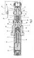
Fig.3 weist ein Ventilgehäuse 38 in der Art einer Einschraubpatrone auf. Am freien stirnseitigen Ende des Ventilgehäuses 38 ist der eine Fluidanschluß 1 angeordnet und entlang des Außenumfanges des Ventilgehäuses 38 durchgreifen in radialer Richtung die weiteren Fluidanschlüsse 2, 3 und 4 das dahingehende Ventilgehäuse 38. Die einzelnen Fluidanschlüsse 1, 2, 3 und 4 sind entsprechend über außenumfangsseitig am Ventilgehäuse 38 angeordnete Dichtungen voneinander fluiddicht getrennt. Des weiteren ist, wie in derFig.3 symbolhaft dargestellt, das Wechselventil 32 mit seinen Eingangsseiten an die Fluidanschlüsse 1, 2 und 3 angeschlossen sowie an die Anschlußstellen 36, die gemäß der Darstellung nach derFig.2 in die Versorgungsleitungen 20 münden (inFig.3 nicht dargestellt). - Das Ventilgehäuse 38 ist, wie dargestellt, in der Art einer Einschraubpatrone ausgebildet und kann dergestalt in einen nicht näher dargestellten Anschlußblock des Fahrantriebes mit seiner gesamthydraulischen Anlage eingeschraubt werden. An seinem, dem Fluidanschluß 1 gegenüberliegenden Ende ist das Ventilgehäuse 38 mit einer Steuereinrichtung 40 versehen, die in der Art eines Magnetsystems ausgebildet einen Magnetanker 42 aufweist, der mittels einer Spule bestrombar (nicht näher dargestellt) sich innerhalb eines Polrohres 44 hin und her bewegen kann und dabei zur Ansteuerung eines Schließteils 48 in der Form eines Schließkegels auf eine Betätigungsstange 46 einwirkt. Schließteil 48 und Betätigungsstange 46 sind über eine Druckfeder 50 als Energiespeicher voneinander getrennt. Sowohl das Schließteil 48 als auch die Druckfeder 50 sowie das vordere, dem Magnetanker 42 abgekehrte Ende der Betätigungsstange 46 sind in einem Fluidraum 52 geführt, der über den Fluidanschluß 4 fluidführend verbindbar ist mit der Verbindungsleitung 34 nach der
Fig.2 , die mit ihrem freien Ende in den Tank 16 mündet. - Innerhalb des Ventilgehäuses 38 ist ein Ventilkolben 56 geführt, wobei der Ventilkolben 56 eine Art Hauptstufe ausbildet und das Bauteil 58 stellt den Vorsteuersitz des Ventiles dar in der Art einer Vorstufe. Der Ventilkolben 56 begrenzt mit seinem einen stirnseitigen Ende einen weiteren Fluidraum 60, in dem als weiterer Energiespeicher eine Druckfeder 62 geführt ist, die in eine hohlzylindrische Ausnehmung im Ventilkolben 56 eingreift. Der Ventilkolben 56 ist ferner außenumfangsseitig mit einer Radialausnehmung 64 versehen, deren axiale Länge in Längsrichtung des Ventils gesehen derart bemessen ist, dass in vorgebbaren Schalt- oder Verschiebestel lungen des Ventilkolbens 56 jedenfalls partiell ein fluidführender Weg zwischen den Fluidanschlüssen 2 und 3 freigegeben und wieder, wie in der
Fig.3 dargestellt, sperrbar ist. Sowohl der Ventilkolben 56 als auch der Vorsteuersitz 58 weisen in Längsrichtung durchgehende Fluidkanäle 66,68 auf, die in Blickrichtung auf dieFig.3 gesehen an ihrem rechten Ende jeweils eine Blende 70 aufweisen, die den Fluidstrom drosseln, der an dem Fluidanschluß 1 ansteht. - Das in der
Fig.3 dargestellte Proportionalventil kann in beide Richtungen, also vom Fluidanschluß 2 zum Fluidanschluß 3 oder umgekehrt von Fluidanschluß 3 zu Fluidanschluß 2, durchströmt werden. Die Richtung der Durchströmung wird unter anderem dadurch bestimmt, wo jeweils der höchste Verbraucherdruck in den Versorgungsleitungen 20 ansteht. Der dahingehende Verbraucherdruck wird durch das Wechselventil 32 über eine Meldeleitung 72 zum Fluidanschluß 1 des Proportionalventils gemeldet. Wird der durch das Magnetsystem der Steuereinrichtung 4' einstellbare Schließdruck überschritten, indem der am Fluidanschluß 1 anstehende Verbraucherdruck das Schließteil 48 vom Vorsteuersitz 58 als Vorstufe abhebt, öffnet dergestalt die Vorsteuerung und der als Hauptstufe konzipierte Ventilkolben 56 bewegt sich gegen die Kraft des Energiespeichers in Form der Druckfeder 62 nach links. Dadurch wird die fluidführende Verbindung von Fluidanschluß 2 nach Fluidanschluß 3 geöffnet und Fluid (Öl) kann vom höheren zum niedrigeren Druckniveau fließen. Im unbestromten Zustand, also bei nicht aktiviertem Magnetsystem, erfüllt das Proportionalventil die Forderung nach einem drucklosen Ölumlauf einer Achse (Achse im Freilauf), wofür bisher ein zusätzliches 2/2-Wege-Ventil 22 (vgl.Fig.1 ) nach dem Stand der Technik notwendig war. - Bei einer teilbestomten Einstellung des Magnetsystems und mithin teilweiser Aktivierung des Magnetankers 42 ist mit der erfindungsgemäßen Ventillösung die Funktion der beschriebenen Vorspannung realisiert, bei der der Hydromotor 10 über einen definierten Druck abzubremsen ist, wobei mit der erfindungsgemäßen Lösung über die Magnetkraft des Magnetsystems die Bremswirkung proportional eingestellt werden kann. Die dahingehende Ventilfunktion ersetzt dann insoweit die bisherige Kombination von Druckbegrenzungsventil 26 mit 2/2-Wege-Ventil 24 als Gesamtvorspannungssystem (vgl.
Fig.1 ). Bei voller Bestromung und mithin höchster Magnetschließkraft erfüllt das erfindungsgemäße Proportionalventil die Funktion der bisher bekannten Schockventile 28 als eigenständige Druckbegrenzungsventile. Ein weiterer Vorteil der erfindungsgemäßen Lösung ist, dass die Referenz des Proportionalventils gegen den Druck im Tank 16 gelegt werden kann, so dass sich die Drücke auf der Abflußseite nicht mehr auf den eingestellten Druck addieren können. - Die geänderten Ausführungsformen nach den
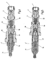
Fig.4 und 5 werden nur noch insofern erläutert, als sie sich wesentlich von der Ventilkonstruktion nach derFig.3 unterscheiden. Von ihrem eigentlichen Ventilaufbau her entsprechen sich die drei Lösungen nach denFig.3 bis 5 und die wesentlichen Unterschiede sind nur im Umfang der Ausbildung der jeweiligen Steuereinrichtung 4' zu sehen. - Bei der Ausführungsform nach der
Fig.4 wurde das Magnetsystem als Steuereinrichtung 4' durch eine mechanische Voreinstellung ersetzt, mit der über eine Spindel 74 und eine Kraftfeder 76 der Schließdruck für das Schließteil 48 von Hand vorgebbar ist. Das Ventil ist als doppelt wirkendes vorgesteuertes Schockventil mit Tankreferenz über die Verbindungsleitung 34 ausgestaltet, wobei die Doppelwirkung auf der Entkoppelung des Steueranschlusses 1 von den Verbraucheranschlüssen 3 und 4 beruht. Die dahingehende Ventilvariante ist sowohl definiert (schwarz/weiß - Schaltverhalten) als auch proportional ansteuerbar. - Während die Ausführungsform nach der
Fig.3 ein sog. drückendes Magnetsystem aufweist, bei dem im bestromten Zustand der Magnetanker 42 über die Betätigungsstange 46 das Schließteil 48 in seiner den Kanal 68 sperrenden Schließstellung zu halten sucht, ist bei der Lösung nach derFig.5 das Magnetsystem mit Magnetanker 42 als sog. ziehendes System ausgebildet, bei dem der Magnetanker 42 unter dem Einfluß einer bestromten Wicklungsspule (nicht dargestellt) in Blickrichtung auf dieFig. 5 gesehen von rechts nach links verfährt entgegen der Wirkung der Kraftfeder 76 als Teil einer mechanischen Voreinstellung gemäß der Lösung nach derFig.4 . Das Ausführungsbeispiel nach derFig. 5 kombiniert also ein ziehend wirkendes Magnetsystem mit einer mechanischen Voreinstellung gemäß der Lösung nach derFig.4 . Ist das zuordenbare Polrohr 44 als sog. Fail-Safe-Polrohr ausgebildet, ergibt dies die Möglichkeit von weiteren Varianten. So würde bei voller Bestromung ein druckloser Umlauf ermöglicht und im unbestromten Zustand des Magnetsystems als Schalteinrichtung 4' hätte man eine Art Fail-Safe-Ventil mit der Funktion eines doppelt wirkenden vorgesteuerten Schockventils mit Tankreferenz. Der Maximaldruck kann dann, ähnlich wie bei einem normalen Druckbegrenzungsventil, manuell eingestellt werden. Der dahingehend stromlose Zustand ist dergestalt in derFig. 5 wiedergegeben. - Wird der erfindungsgemäße Proportionalantrieb bei dem beschriebenen hydraulischen Fahrzeugantrieb eingesetzt, ist eine deutliche Reduzierung der Anzahl der benötigten Ventile möglich und insgesamt verkleinert sich der Bauraum für die Ventillösung. Da das erfindungsgemäße Proportionalventil in beiden Richtungen durchströmbar ist, fällt insoweit auch die doppelte Anzahl der Ventile gemäß der bekannten Lösung nach der
Fig.1 weg. Ausgehend von der Überlegung, dass keine zwei Funktionen gleichzeitig ablaufen müssen, kann man dergestalt auf die alternative Schaltung des Proportionalventils gemäß einer hydraulischen Schaltlösung nach derFig.2 zurückgreifen und damit die Vielzahl an Ventilen einsparen, was insgesamt die Herstell- und Wartungskosten reduzieren hilft. Das erfindungsgemäße Proportionalventil braucht aber nicht auf die Verwendung von Fahrzeugantrieben eingeschränkt zu sein, sondern kann insbesondere aufgrund seines stabilen Schaltverhaltens auch in sonstigen hydraulischen Kreisläufen Anwendung finden, insbesondere wo auf erhöhte Sicherheitsanforderungen Wert gelegt wird.
Claims (10)
- Ventil, insbesondere Proportional-Druckbegrenzungsventil, mit einem Ventilgehäuse (38) mit mindestens drei Fluidanschlüssen (1,2,3), wobei das Ventil an ein hydraulisches Antriebssystem mit einem vorgebbaren Verbraucherdruck anschließbar ist, wobei mittels einer Steuereinrichtung (40) ein Ventilkolben (56) ansteuerbar ist, der mittels eines Energiespeichers (62) in Wirkverbindung mit einem Vorsteuersitz (58) steht, dadurch gekennzeichnet, dass der anstehende Verbraucherdruck an einem Fluidanschluß (1) zumindest derart auf den Ventilkolben (56) einwirkt, dass abhängig vom anstehenden Verbraucherdruck und von der Betätigungskraft der Steuereinrichtung (40) eine Fluiddurchströmung zwischen den beiden anderen Fluidanschlüssen (2 und 3) in beiden Richtungen innerhalb des Ventilgehäuses (38) möglich ist.
- Ventil nach Anspruch 1, dadurch gekennzeichnet, dass zwischen die beiden anderen Fluidanschlüsse (2,3) ein Wechselventil (32) geschaltet ist, das über eine Meldeleitung (72) den höchsten Verbraucherdruck an den einen Fluidanschluß (1) wiedergibt.
- Ventil nach Anspruch 1 oder 2, dadurch gekennzeichnet, dass der eine Fluidanschluß (1) stirnseitig in das freie Ende des Ventilgehäuses (38) mündet und dass die beiden anderen Fluidanschlüsse (2,3) entlang seines Außenumfanges das Ventilgehäuse (38) durchgreifen und mittels des einen Ventilkolbens (56) als Hauptstufe abhängig von seiner Stellung miteinander fluidführend verbindbar sind.
- Ventil nach Anspruch 3, dadurch gekennzeichnet, dass der Vorsteuersitz (58) in der Art einer Vorstufe wirkt und von der Steuereinrichtung (4') mit einer vorgebbaren Betätigungskraft beaufschlagbar ist.
- Ventil nach einem der Ansprüche 1 bis 4, dadurch gekennzeichnet, dass der Energiespeicher zwischen dem Ventilkolben (56) und dem Vorsteuersitz (58) als Druckfeder (62) ausgebildet ist.
- Ventil nach einem der Ansprüche 1 bis 5, dadurch gekennzeichnet, dass der Ventilkolben (56) und der Vorsteuersitz (58) jeweils von einem Verbindungskanal (66,68) durchgriffen sind, der an seiner dem Verbraucherdruck zugewandten Seite mit einer Blende (70) oder Drossel versehen ist.
- Ventil nach Anspruch 6, dadurch gekennzeichnet, dass der Verbindungskanal (68) des Vorsteuersitzes (58) von einem Schließteil (48) der Steuereinrichtung (4') verschließbar ist.
- Ventil nach einem der Ansprüche 1 bis 7, dadurch gekennzeichnet, dass der Ventilkolben (56) und der Vorsteuersitz (58) mittels des Energiespeichers unter Bildung eines Fluidraums (60) auf Abstand zueinander gehalten sind.
- Ventil nach einem der Ansprüche 1 bis 8, dadurch gekennzeichnet, dass die Steuereinrichtung (4') ein Magnetsystem mit ansteuerbarem Magnetanker (42) aufweist, der auf den Ventilkolben (56) und den Vorsteuersitz (58) einwirkt, oder aus einer mechanischen Voreinstellung (74) besteht oder aus eine Kombination von Magnetsystem mit mechanischer Voreinstellung.
- Ventil nach einem der Ansprüche 1 bis 9, dadurch gekennzeichnet, dass es einen weiteren vierten Fluidanschluß (4) aufweist, der zur drucklosen Ableitung des Vorsteueröls dient.
Applications Claiming Priority (2)
| Application Number | Priority Date | Filing Date | Title |
|---|---|---|---|
| DE102005006321A DE102005006321A1 (de) | 2005-02-11 | 2005-02-11 | Ventil, insbesondere Proportinal-Druckbegrenzungsventil |
| PCT/EP2006/000620 WO2006084576A1 (de) | 2005-02-11 | 2006-01-25 | Ventil, insbesondere proportional-druckbegrenzungsventil |
Publications (2)
| Publication Number | Publication Date |
|---|---|
| EP1846807A1 EP1846807A1 (de) | 2007-10-24 |
| EP1846807B1 true EP1846807B1 (de) | 2010-07-07 |
Family
ID=36224448
Family Applications (1)
| Application Number | Title | Priority Date | Filing Date |
|---|---|---|---|
| EP20060706391 Expired - Lifetime EP1846807B1 (de) | 2005-02-11 | 2006-01-25 | Ventil, insbesondere proportional-druckbegrenzungsventil |
Country Status (8)
| Country | Link |
|---|---|
| US (1) | US7841360B2 (de) |
| EP (1) | EP1846807B1 (de) |
| JP (1) | JP5026990B2 (de) |
| KR (1) | KR101225466B1 (de) |
| CN (1) | CN100514241C (de) |
| AT (1) | ATE473477T1 (de) |
| DE (2) | DE102005006321A1 (de) |
| WO (1) | WO2006084576A1 (de) |
Families Citing this family (45)
| Publication number | Priority date | Publication date | Assignee | Title |
|---|---|---|---|---|
| DE102007015077A1 (de) | 2007-03-29 | 2008-10-09 | Hydac Fluidtechnik Gmbh | Schieberventil für Hydrauliksysteme |
| FI123634B (fi) | 2007-10-05 | 2013-08-30 | Sandvik Mining & Constr Oy | Kallionrikkomislaite, suojaventtiili sekä menetelmä kallionrikkomislaitteen käyttämiseksi |
| DE102008057415B3 (de) * | 2008-11-14 | 2010-06-17 | Hoerbiger Automatisierungstechnik Holding Gmbh | Maschine zur Bearbeitung eines Werkstücks mittels eines Laserstrahls |
| IT1396001B1 (it) * | 2009-04-28 | 2012-11-09 | Nuovo Pignone Spa | Sistema di recupero dell'energia in un impianto per la compressione di gas |
| CN101907119B (zh) * | 2010-07-23 | 2012-04-25 | 林友根 | 带有卸荷溢流阀的铰接螺栓 |
| JP5504423B2 (ja) * | 2010-08-27 | 2014-05-28 | 日立建機株式会社 | 油圧作業機の油圧駆動装置 |
| DE102011110257B3 (de) | 2011-06-06 | 2012-07-26 | Hydac Fluidtechnik Gmbh | Ventil, insbesondere Druckregelventil oderDruckbegrenzungsventil |
| US8926632B2 (en) | 2011-06-08 | 2015-01-06 | Zimmer Surgical, Inc. | Dermatome swivel double acting valve |
| CN102588372B (zh) * | 2012-03-09 | 2014-12-03 | 太原理工大学 | 一种电液比例溢流阀 |
| JP5872363B2 (ja) * | 2012-03-30 | 2016-03-01 | 住友建機株式会社 | 旋回制御装置 |
| DE102012010522A1 (de) * | 2012-05-25 | 2013-11-28 | Hydac Fluidtechnik Gmbh | Ventil für Ventilanordnung |
| CN102734248B (zh) * | 2012-07-18 | 2015-05-27 | 严光贤 | 一种溢流阀 |
| CN102818046A (zh) * | 2012-08-30 | 2012-12-12 | 三一重型装备有限公司 | 减压阀、掘进机水系统及掘进机 |
| CN103851211B (zh) * | 2012-11-30 | 2017-05-17 | 上海航天控制工程研究所 | 一种增益可调的压力比例电磁阀滑阀级结构 |
| DE102013201864A1 (de) * | 2013-02-05 | 2014-08-07 | Robert Bosch Gmbh | Bremsventil und hydrostatisches Antriebssystem hiermit |
| US9657749B2 (en) | 2013-03-11 | 2017-05-23 | Hydraforce, Inc. | Hydraulic suspension for vehicle and multi-functional proportional control valve for the same |
| DE102013014558A1 (de) * | 2013-08-31 | 2015-03-05 | Hydac Fluidtechnik Gmbh | Ventil nebst seiner Verwendung für eine Kupplung |
| CN103470561B (zh) * | 2013-09-03 | 2015-10-21 | 浙江大学 | 一种比例溢流阀 |
| CN104214264B (zh) * | 2014-08-01 | 2017-01-11 | 安徽工程大学 | 一种多维减振平台的阻尼刚度可调的液力减振器 |
| CN104344017B (zh) * | 2014-10-28 | 2016-05-25 | 华中科技大学 | 一种平面密封型换向阀 |
| JP6530177B2 (ja) * | 2014-11-06 | 2019-06-12 | 株式会社コスメック | リリーフ弁装置 |
| DE102014119679A1 (de) * | 2014-12-29 | 2016-06-30 | Aesculap Ag | Medizinischer Handgriff mit pneumatischer Sicherheitskupplung |
| WO2018153888A1 (en) * | 2017-02-24 | 2018-08-30 | Merck Patent Gmbh | Fluid distributor valve and water purification and dispensing system using the same |
| CN107178649B (zh) * | 2017-07-11 | 2023-10-03 | 江苏农牧科技职业学院 | 汽车转向阀用整体式电控比例阀及其控制方法 |
| CN107461516A (zh) * | 2017-08-02 | 2017-12-12 | 北京航空航天大学 | 一种差动式电液比例定差减压阀 |
| DE102017008359A1 (de) * | 2017-09-06 | 2019-03-07 | Hydac Fluidtechnik Gmbh | Ventil |
| US10437269B1 (en) * | 2017-10-06 | 2019-10-08 | Sun Hydraulics, Llc | Electrohydraulic counterbalance and pressure relief valve |
| CN107504006B (zh) * | 2017-10-19 | 2019-07-09 | 杭州富阳中亚阀业有限公司 | 一种常开比例单向流量阀 |
| CN107542719B (zh) * | 2017-10-24 | 2019-12-20 | 江苏盐邦泵业制造有限公司 | 常开比例单向流量阀 |
| US10794510B1 (en) | 2017-12-20 | 2020-10-06 | Sun Hydraulics, Llc | Electrohydraulic counterbalance and pressure relief valve |
| CN107939767A (zh) * | 2017-12-28 | 2018-04-20 | 邵立坤 | 一种补油缓冲阀 |
| US10495117B1 (en) | 2018-04-17 | 2019-12-03 | Sun Hydraulics, Llc | Electrohydraulic counterbalance and pressure relief valve |
| CN108691838B (zh) * | 2018-07-26 | 2021-08-06 | 江苏军源装备制造有限公司 | 集成阀 |
| US10683879B1 (en) | 2019-01-22 | 2020-06-16 | Sun Hydraulics, Llc | Two-port electrohydraulic counterbalance valve |
| US11035482B2 (en) * | 2019-01-31 | 2021-06-15 | Scott Dale Follett | Pressure relief valve |
| US11092354B2 (en) | 2019-06-20 | 2021-08-17 | Johnson Controls Tyco IP Holdings LLP | Systems and methods for flow control in an HVAC system |
| US11149976B2 (en) | 2019-06-20 | 2021-10-19 | Johnson Controls Tyco IP Holdings LLP | Systems and methods for flow control in an HVAC system |
| US20220259829A1 (en) * | 2019-07-08 | 2022-08-18 | Danfoss Power Solutions Ii Technology A/S | Hydraulic system architectures and bidirectional proportional valves usable in the system architectures |
| US11391480B2 (en) | 2019-12-04 | 2022-07-19 | Johnson Controls Tyco IP Holdings LLP | Systems and methods for freeze protection of a coil in an HVAC system |
| US11624524B2 (en) | 2019-12-30 | 2023-04-11 | Johnson Controls Tyco IP Holdings LLP | Systems and methods for expedited flow sensor calibration |
| CN111102263A (zh) * | 2020-01-22 | 2020-05-05 | 浙江高宇液压机电有限公司 | 一种具有卸荷控制通道的先导式溢流阀 |
| CN111456977A (zh) * | 2020-04-09 | 2020-07-28 | 上海诺玛液压系统有限公司 | 高压大流量反比例溢流阀 |
| US12085099B1 (en) * | 2020-06-18 | 2024-09-10 | Vacuworx Global, LLC | Flow control block for use with a vacuum material handler |
| US12247556B2 (en) * | 2022-06-14 | 2025-03-11 | Hydac Fluidtechnik Gmbh | Pump device |
| US12460736B2 (en) * | 2024-01-02 | 2025-11-04 | Solero Technologies, Llc | Smart damping control valve |
Family Cites Families (27)
| Publication number | Priority date | Publication date | Assignee | Title |
|---|---|---|---|---|
| US3667722A (en) * | 1970-10-22 | 1972-06-06 | Ite Imperial Corp | Proportional valve |
| JPS50134028U (de) * | 1974-04-19 | 1975-11-05 | ||
| JPS5169769A (en) * | 1974-12-14 | 1976-06-16 | Kawasaki Heavy Ind Ltd | Ekiatsusochino ryuryoseigyokairo |
| JPS5276584A (en) * | 1975-12-22 | 1977-06-28 | Nippon Air Brake Co | Liquid flow rate regulating device for hydraulic flow direction shifting valve |
| FR2452647A1 (fr) * | 1979-03-26 | 1980-10-24 | Renault | Servo-valve |
| DE2914196C2 (de) * | 1979-04-07 | 1985-11-14 | Mannesmann Rexroth GmbH, 8770 Lohr | Ventil zum Steuern von Druckmittel |
| DE3307554C2 (de) * | 1983-03-03 | 1985-09-26 | Mannesmann Rexroth GmbH, 8770 Lohr | Elektrisch regelbares Druckreduzierventil |
| JPS59158701U (ja) * | 1983-04-09 | 1984-10-24 | 内田油圧機器工業株式会社 | 圧力制御装置 |
| US4699351A (en) * | 1984-07-11 | 1987-10-13 | Target Rock Corporation | Pressure responsive, pilot actuated, modulating valve |
| KR930001020B1 (ko) * | 1987-06-16 | 1993-02-12 | 스미도모 덴기 고오교오 가부시기가이샤 | 액압 제어장치 및 이것을 사용한 브레이크장치 |
| US4799645A (en) * | 1988-01-19 | 1989-01-24 | Deere & Company | Pilot operated hydraulic control valve |
| US5072752A (en) * | 1991-03-14 | 1991-12-17 | Sterling Hydraulics, Inc. | Bidirectional cartridge valve |
| US5836335A (en) * | 1991-08-19 | 1998-11-17 | Fluid Power Industries, Inc. | Proportional pressure control valve |
| JPH05321907A (ja) * | 1992-05-15 | 1993-12-07 | Hitachi Constr Mach Co Ltd | 慣性体反転防止弁 |
| LU88277A1 (de) * | 1993-05-27 | 1994-12-01 | Hydrolux Sarl | Vorgesteuertes Servoventil |
| US5366202A (en) * | 1993-07-06 | 1994-11-22 | Caterpillar Inc. | Displacement controlled hydraulic proportional valve |
| DE4324589C2 (de) | 1993-07-22 | 1995-12-21 | Bosch Gmbh Robert | Elektromagnetisch betätigbares Druckregelventil |
| DE4330073A1 (de) * | 1993-09-06 | 1995-03-09 | Frutigen Hydrotechnik Ag | Vorgesteuertes Hydraulikventil |
| US5350152A (en) * | 1993-12-27 | 1994-09-27 | Caterpillar Inc. | Displacement controlled hydraulic proportional valve |
| DE4402580B4 (de) | 1994-01-28 | 2006-12-14 | Linde Ag | Hydraulisches Antriebssystem |
| DE4423629A1 (de) | 1994-07-06 | 1996-01-11 | Rexroth Mannesmann Gmbh | Hydraulisches Ventil, das insbesondere zur Verwendung in einem Kraftfahrzeug vorgesehen ist |
| US6073652A (en) * | 1999-04-01 | 2000-06-13 | Husco International, Inc. | Pilot solenoid control valve with integral pressure sensing transducer |
| DE10150238C2 (de) * | 2001-10-11 | 2003-09-25 | Hydac Fluidtechnik Gmbh | Druckregelventil, insbesondere Proportional-Druckregelventil |
| JP2003184810A (ja) * | 2001-12-19 | 2003-07-03 | Shin Caterpillar Mitsubishi Ltd | 作業機械における油圧回路 |
| US6904937B2 (en) * | 2002-12-11 | 2005-06-14 | Delphi Technologies, Inc. | Switchable fluid control valve system |
| US6869060B2 (en) * | 2003-04-04 | 2005-03-22 | Husco International, Inc. | Hydraulic poppet valve with force feedback |
| DE10323595A1 (de) * | 2003-05-16 | 2004-12-09 | Hydac Fluidtechnik Gmbh | Ventil |
-
2005
- 2005-02-11 DE DE102005006321A patent/DE102005006321A1/de not_active Withdrawn
-
2006
- 2006-01-25 US US11/795,761 patent/US7841360B2/en not_active Expired - Fee Related
- 2006-01-25 KR KR1020077018368A patent/KR101225466B1/ko not_active Expired - Lifetime
- 2006-01-25 DE DE200650007369 patent/DE502006007369D1/de not_active Expired - Lifetime
- 2006-01-25 JP JP2007554463A patent/JP5026990B2/ja not_active Expired - Lifetime
- 2006-01-25 WO PCT/EP2006/000620 patent/WO2006084576A1/de not_active Ceased
- 2006-01-25 AT AT06706391T patent/ATE473477T1/de active
- 2006-01-25 EP EP20060706391 patent/EP1846807B1/de not_active Expired - Lifetime
- 2006-01-25 CN CNB2006800045773A patent/CN100514241C/zh not_active Expired - Fee Related
Also Published As
| Publication number | Publication date |
|---|---|
| CN101124525A (zh) | 2008-02-13 |
| US20080115848A1 (en) | 2008-05-22 |
| KR20070102543A (ko) | 2007-10-18 |
| CN100514241C (zh) | 2009-07-15 |
| ATE473477T1 (de) | 2010-07-15 |
| WO2006084576A1 (de) | 2006-08-17 |
| EP1846807A1 (de) | 2007-10-24 |
| KR101225466B1 (ko) | 2013-01-24 |
| DE102005006321A1 (de) | 2006-08-17 |
| JP2008530457A (ja) | 2008-08-07 |
| DE502006007369D1 (de) | 2010-08-19 |
| JP5026990B2 (ja) | 2012-09-19 |
| US7841360B2 (en) | 2010-11-30 |
Similar Documents
| Publication | Publication Date | Title |
|---|---|---|
| DE102005006321A1 (de) | Ventil, insbesondere Proportinal-Druckbegrenzungsventil | |
| DE102014018788B3 (de) | Kraftfahrzeug-Fahrgestell | |
| EP1369598B1 (de) | Elektrohydraulische Hubsteuervorrichtung für Flurförderfahrzeuge | |
| EP1522754B1 (de) | Druckmedium-Notversorgung für ein Kupplungssystem und ein die Druckmedium-Notversorgung aufweisender Kraftfahrzeug-Antriebsstrang | |
| WO2012104046A1 (de) | Hydraulische stellanordnung | |
| DE4124384C1 (de) | ||
| EP2220380A1 (de) | Hydraulische ventilvorrichtung | |
| EP1508488B2 (de) | Verfahren zum Betreiben einer Druckluftbeschaffungsanlage eines Kraftfahrzeuges sowie Druckluftaufbereitungseinrichtung | |
| DE102009038377A1 (de) | Hydraulikanordnung | |
| DE10128805B4 (de) | Eelektro-hydraulisches Steuerungssystem zum Steuern von Gangwechseln bei teil- oder vollautomatischen Getrieben von Fahrzeugen | |
| WO2003048587A1 (de) | Antrieb | |
| DE102014211582A1 (de) | Elektronisch schlupfregelbare Fahrzeugbremsanlage | |
| DE4221088C2 (de) | Aufhängungssystem für Fahrzeuge | |
| DE102013213537A1 (de) | Steuereinrichtung für einen mit einem Arbeitsfluid betriebenen Aktor und Verfahren zum Betreiben der Steuereinrichtung | |
| DE102004057739A1 (de) | Bremseinrichtung | |
| DE4409928A1 (de) | Hydraulischer Stellantrieb für die Achslenkung eines Kraftfahrzeuges | |
| EP3348430B1 (de) | Hydraulisches dämpfungssystem und gelenkfahrzeug mit einem derartigen dämpfungssystem | |
| EP2157319B1 (de) | Hydrauliksteuerung für einen Hydromotor | |
| DE102016006545A1 (de) | Ventilvorrichtung | |
| EP2199186B1 (de) | Hydraulische Lenksteuervorrichtung | |
| AT396618B (de) | Hydraulisches dreiwege-stetigventil für blockeinbau | |
| DE4418881A1 (de) | Hubwerkregelsystem mit Regelventil | |
| EP0717201B1 (de) | Schutzsystem für eine Druckmittelanlage | |
| DE102010055716A1 (de) | Hydraulischer Antrieb | |
| EP0376023B1 (de) | Elektrohydraulisches Proportionalwegeventil |
Legal Events
| Date | Code | Title | Description |
|---|---|---|---|
| PUAI | Public reference made under article 153(3) epc to a published international application that has entered the european phase |
Free format text: ORIGINAL CODE: 0009012 |
|
| 17P | Request for examination filed |
Effective date: 20070523 |
|
| AK | Designated contracting states |
Kind code of ref document: A1 Designated state(s): AT BE BG CH CY CZ DE DK EE ES FI FR GB GR HU IE IS IT LI LT LU LV MC NL PL PT RO SE SI SK TR |
|
| DAX | Request for extension of the european patent (deleted) | ||
| 17Q | First examination report despatched |
Effective date: 20090209 |
|
| GRAP | Despatch of communication of intention to grant a patent |
Free format text: ORIGINAL CODE: EPIDOSNIGR1 |
|
| RTI1 | Title (correction) |
Free format text: VALVE, ESPECIALLY PROPORTIONAL PRESSURE RELIEF VALVE |
|
| GRAS | Grant fee paid |
Free format text: ORIGINAL CODE: EPIDOSNIGR3 |
|
| GRAA | (expected) grant |
Free format text: ORIGINAL CODE: 0009210 |
|
| AK | Designated contracting states |
Kind code of ref document: B1 Designated state(s): AT BE BG CH CY CZ DE DK EE ES FI FR GB GR HU IE IS IT LI LT LU LV MC NL PL PT RO SE SI SK TR |
|
| REG | Reference to a national code |
Ref country code: GB Ref legal event code: FG4D Free format text: NOT ENGLISH |
|
| REG | Reference to a national code |
Ref country code: CH Ref legal event code: NV Representative=s name: ISLER & PEDRAZZINI AG Ref country code: CH Ref legal event code: EP |
|
| REG | Reference to a national code |
Ref country code: IE Ref legal event code: FG4D |
|
| REF | Corresponds to: |
Ref document number: 502006007369 Country of ref document: DE Date of ref document: 20100819 Kind code of ref document: P |
|
| REG | Reference to a national code |
Ref country code: SE Ref legal event code: TRGR |
|
| REG | Reference to a national code |
Ref country code: NL Ref legal event code: VDEP Effective date: 20100707 |
|
| PG25 | Lapsed in a contracting state [announced via postgrant information from national office to epo] |
Ref country code: SI Free format text: LAPSE BECAUSE OF FAILURE TO SUBMIT A TRANSLATION OF THE DESCRIPTION OR TO PAY THE FEE WITHIN THE PRESCRIBED TIME-LIMIT Effective date: 20100707 |
|
| LTIE | Lt: invalidation of european patent or patent extension |
Effective date: 20100707 |
|
| PG25 | Lapsed in a contracting state [announced via postgrant information from national office to epo] |
Ref country code: LT Free format text: LAPSE BECAUSE OF FAILURE TO SUBMIT A TRANSLATION OF THE DESCRIPTION OR TO PAY THE FEE WITHIN THE PRESCRIBED TIME-LIMIT Effective date: 20100707 Ref country code: FI Free format text: LAPSE BECAUSE OF FAILURE TO SUBMIT A TRANSLATION OF THE DESCRIPTION OR TO PAY THE FEE WITHIN THE PRESCRIBED TIME-LIMIT Effective date: 20100707 Ref country code: NL Free format text: LAPSE BECAUSE OF FAILURE TO SUBMIT A TRANSLATION OF THE DESCRIPTION OR TO PAY THE FEE WITHIN THE PRESCRIBED TIME-LIMIT Effective date: 20100707 |
|
| REG | Reference to a national code |
Ref country code: IE Ref legal event code: FD4D |
|
| PG25 | Lapsed in a contracting state [announced via postgrant information from national office to epo] |
Ref country code: PL Free format text: LAPSE BECAUSE OF FAILURE TO SUBMIT A TRANSLATION OF THE DESCRIPTION OR TO PAY THE FEE WITHIN THE PRESCRIBED TIME-LIMIT Effective date: 20100707 Ref country code: CY Free format text: LAPSE BECAUSE OF FAILURE TO SUBMIT A TRANSLATION OF THE DESCRIPTION OR TO PAY THE FEE WITHIN THE PRESCRIBED TIME-LIMIT Effective date: 20100707 Ref country code: PT Free format text: LAPSE BECAUSE OF FAILURE TO SUBMIT A TRANSLATION OF THE DESCRIPTION OR TO PAY THE FEE WITHIN THE PRESCRIBED TIME-LIMIT Effective date: 20101108 Ref country code: BG Free format text: LAPSE BECAUSE OF FAILURE TO SUBMIT A TRANSLATION OF THE DESCRIPTION OR TO PAY THE FEE WITHIN THE PRESCRIBED TIME-LIMIT Effective date: 20101007 Ref country code: IS Free format text: LAPSE BECAUSE OF FAILURE TO SUBMIT A TRANSLATION OF THE DESCRIPTION OR TO PAY THE FEE WITHIN THE PRESCRIBED TIME-LIMIT Effective date: 20101107 |
|
| PG25 | Lapsed in a contracting state [announced via postgrant information from national office to epo] |
Ref country code: LV Free format text: LAPSE BECAUSE OF FAILURE TO SUBMIT A TRANSLATION OF THE DESCRIPTION OR TO PAY THE FEE WITHIN THE PRESCRIBED TIME-LIMIT Effective date: 20100707 Ref country code: GR Free format text: LAPSE BECAUSE OF FAILURE TO SUBMIT A TRANSLATION OF THE DESCRIPTION OR TO PAY THE FEE WITHIN THE PRESCRIBED TIME-LIMIT Effective date: 20101008 |
|
| PG25 | Lapsed in a contracting state [announced via postgrant information from national office to epo] |
Ref country code: IE Free format text: LAPSE BECAUSE OF FAILURE TO SUBMIT A TRANSLATION OF THE DESCRIPTION OR TO PAY THE FEE WITHIN THE PRESCRIBED TIME-LIMIT Effective date: 20100707 Ref country code: DK Free format text: LAPSE BECAUSE OF FAILURE TO SUBMIT A TRANSLATION OF THE DESCRIPTION OR TO PAY THE FEE WITHIN THE PRESCRIBED TIME-LIMIT Effective date: 20100707 |
|
| PLBE | No opposition filed within time limit |
Free format text: ORIGINAL CODE: 0009261 |
|
| STAA | Information on the status of an ep patent application or granted ep patent |
Free format text: STATUS: NO OPPOSITION FILED WITHIN TIME LIMIT |
|
| PG25 | Lapsed in a contracting state [announced via postgrant information from national office to epo] |
Ref country code: SK Free format text: LAPSE BECAUSE OF FAILURE TO SUBMIT A TRANSLATION OF THE DESCRIPTION OR TO PAY THE FEE WITHIN THE PRESCRIBED TIME-LIMIT Effective date: 20100707 Ref country code: EE Free format text: LAPSE BECAUSE OF FAILURE TO SUBMIT A TRANSLATION OF THE DESCRIPTION OR TO PAY THE FEE WITHIN THE PRESCRIBED TIME-LIMIT Effective date: 20100707 Ref country code: RO Free format text: LAPSE BECAUSE OF FAILURE TO SUBMIT A TRANSLATION OF THE DESCRIPTION OR TO PAY THE FEE WITHIN THE PRESCRIBED TIME-LIMIT Effective date: 20100707 Ref country code: CZ Free format text: LAPSE BECAUSE OF FAILURE TO SUBMIT A TRANSLATION OF THE DESCRIPTION OR TO PAY THE FEE WITHIN THE PRESCRIBED TIME-LIMIT Effective date: 20100707 |
|
| 26N | No opposition filed |
Effective date: 20110408 |
|
| PG25 | Lapsed in a contracting state [announced via postgrant information from national office to epo] |
Ref country code: ES Free format text: LAPSE BECAUSE OF FAILURE TO SUBMIT A TRANSLATION OF THE DESCRIPTION OR TO PAY THE FEE WITHIN THE PRESCRIBED TIME-LIMIT Effective date: 20101018 |
|
| REG | Reference to a national code |
Ref country code: DE Ref legal event code: R097 Ref document number: 502006007369 Country of ref document: DE Effective date: 20110408 |
|
| BERE | Be: lapsed |
Owner name: HYDAC FLUIDTECHNIK G.M.B.H. Effective date: 20110131 |
|
| PG25 | Lapsed in a contracting state [announced via postgrant information from national office to epo] |
Ref country code: MC Free format text: LAPSE BECAUSE OF NON-PAYMENT OF DUE FEES Effective date: 20110131 |
|
| PG25 | Lapsed in a contracting state [announced via postgrant information from national office to epo] |
Ref country code: BE Free format text: LAPSE BECAUSE OF NON-PAYMENT OF DUE FEES Effective date: 20110131 |
|
| PG25 | Lapsed in a contracting state [announced via postgrant information from national office to epo] |
Ref country code: LU Free format text: LAPSE BECAUSE OF NON-PAYMENT OF DUE FEES Effective date: 20110125 |
|
| PG25 | Lapsed in a contracting state [announced via postgrant information from national office to epo] |
Ref country code: TR Free format text: LAPSE BECAUSE OF FAILURE TO SUBMIT A TRANSLATION OF THE DESCRIPTION OR TO PAY THE FEE WITHIN THE PRESCRIBED TIME-LIMIT Effective date: 20100707 |
|
| PG25 | Lapsed in a contracting state [announced via postgrant information from national office to epo] |
Ref country code: HU Free format text: LAPSE BECAUSE OF FAILURE TO SUBMIT A TRANSLATION OF THE DESCRIPTION OR TO PAY THE FEE WITHIN THE PRESCRIBED TIME-LIMIT Effective date: 20100707 |
|
| PGFP | Annual fee paid to national office [announced via postgrant information from national office to epo] |
Ref country code: FR Payment date: 20131119 Year of fee payment: 9 Ref country code: SE Payment date: 20131126 Year of fee payment: 9 |
|
| PGFP | Annual fee paid to national office [announced via postgrant information from national office to epo] |
Ref country code: CH Payment date: 20140110 Year of fee payment: 9 |
|
| PGFP | Annual fee paid to national office [announced via postgrant information from national office to epo] |
Ref country code: AT Payment date: 20140114 Year of fee payment: 9 Ref country code: IT Payment date: 20140113 Year of fee payment: 9 |
|
| REG | Reference to a national code |
Ref country code: CH Ref legal event code: PL |
|
| REG | Reference to a national code |
Ref country code: SE Ref legal event code: EUG |
|
| REG | Reference to a national code |
Ref country code: AT Ref legal event code: MM01 Ref document number: 473477 Country of ref document: AT Kind code of ref document: T Effective date: 20150125 |
|
| PG25 | Lapsed in a contracting state [announced via postgrant information from national office to epo] |
Ref country code: CH Free format text: LAPSE BECAUSE OF NON-PAYMENT OF DUE FEES Effective date: 20150131 Ref country code: LI Free format text: LAPSE BECAUSE OF NON-PAYMENT OF DUE FEES Effective date: 20150131 |
|
| REG | Reference to a national code |
Ref country code: FR Ref legal event code: ST Effective date: 20150930 |
|
| PG25 | Lapsed in a contracting state [announced via postgrant information from national office to epo] |
Ref country code: SE Free format text: LAPSE BECAUSE OF NON-PAYMENT OF DUE FEES Effective date: 20150126 Ref country code: FR Free format text: LAPSE BECAUSE OF NON-PAYMENT OF DUE FEES Effective date: 20150202 Ref country code: AT Free format text: LAPSE BECAUSE OF NON-PAYMENT OF DUE FEES Effective date: 20150125 |
|
| PG25 | Lapsed in a contracting state [announced via postgrant information from national office to epo] |
Ref country code: IT Free format text: LAPSE BECAUSE OF NON-PAYMENT OF DUE FEES Effective date: 20150125 |
|
| PGFP | Annual fee paid to national office [announced via postgrant information from national office to epo] |
Ref country code: GB Payment date: 20181106 Year of fee payment: 14 |
|
| GBPC | Gb: european patent ceased through non-payment of renewal fee |
Effective date: 20200125 |
|
| PG25 | Lapsed in a contracting state [announced via postgrant information from national office to epo] |
Ref country code: GB Free format text: LAPSE BECAUSE OF NON-PAYMENT OF DUE FEES Effective date: 20200125 |
|
| PGFP | Annual fee paid to national office [announced via postgrant information from national office to epo] |
Ref country code: DE Payment date: 20250131 Year of fee payment: 20 |
|
| REG | Reference to a national code |
Ref country code: DE Ref legal event code: R071 Ref document number: 502006007369 Country of ref document: DE |