EP1846630B1 - Element de voie de drainage ou de dallage pour la pose sur couche mince de dalles pour l'assechement ou la ventilation - Google Patents
Element de voie de drainage ou de dallage pour la pose sur couche mince de dalles pour l'assechement ou la ventilation Download PDFInfo
- Publication number
- EP1846630B1 EP1846630B1 EP06706632A EP06706632A EP1846630B1 EP 1846630 B1 EP1846630 B1 EP 1846630B1 EP 06706632 A EP06706632 A EP 06706632A EP 06706632 A EP06706632 A EP 06706632A EP 1846630 B1 EP1846630 B1 EP 1846630B1
- Authority
- EP
- European Patent Office
- Prior art keywords
- projections
- sheet
- base surface
- supporting film
- mortar
- Prior art date
- Legal status (The legal status is an assumption and is not a legal conclusion. Google has not performed a legal analysis and makes no representation as to the accuracy of the status listed.)
- Active
Links
- 239000000463 material Substances 0.000 title claims abstract description 126
- 239000004570 mortar (masonry) Substances 0.000 title claims abstract description 44
- 239000011521 glass Substances 0.000 claims abstract description 30
- 239000004033 plastic Substances 0.000 claims abstract description 14
- 229920003023 plastic Polymers 0.000 claims abstract description 14
- 230000009969 flowable effect Effects 0.000 claims abstract description 7
- 230000000694 effects Effects 0.000 claims abstract 3
- 239000000853 adhesive Substances 0.000 claims description 18
- 230000001070 adhesive effect Effects 0.000 claims description 18
- 230000002787 reinforcement Effects 0.000 claims description 11
- 125000006850 spacer group Chemical group 0.000 claims description 10
- 230000001788 irregular Effects 0.000 claims description 3
- 230000007704 transition Effects 0.000 claims description 3
- 230000003014 reinforcing effect Effects 0.000 abstract description 3
- 239000003292 glue Substances 0.000 abstract 2
- 239000002689 soil Substances 0.000 abstract 2
- 239000010410 layer Substances 0.000 description 32
- 239000010408 film Substances 0.000 description 31
- 239000002585 base Substances 0.000 description 25
- 239000000758 substrate Substances 0.000 description 12
- 239000004744 fabric Substances 0.000 description 11
- 239000012790 adhesive layer Substances 0.000 description 7
- XLYOFNOQVPJJNP-UHFFFAOYSA-N water Substances O XLYOFNOQVPJJNP-UHFFFAOYSA-N 0.000 description 6
- 230000004048 modification Effects 0.000 description 5
- 238000012986 modification Methods 0.000 description 5
- 239000007788 liquid Substances 0.000 description 4
- 239000011888 foil Substances 0.000 description 3
- 238000009434 installation Methods 0.000 description 3
- 239000002985 plastic film Substances 0.000 description 3
- 229920006255 plastic film Polymers 0.000 description 3
- 238000004873 anchoring Methods 0.000 description 2
- 238000009435 building construction Methods 0.000 description 2
- 239000011248 coating agent Substances 0.000 description 2
- 238000000576 coating method Methods 0.000 description 2
- 238000010276 construction Methods 0.000 description 2
- 230000006378 damage Effects 0.000 description 2
- 238000009408 flooring Methods 0.000 description 2
- 230000008014 freezing Effects 0.000 description 2
- 238000007710 freezing Methods 0.000 description 2
- 239000012774 insulation material Substances 0.000 description 2
- 239000002184 metal Substances 0.000 description 2
- 230000002093 peripheral effect Effects 0.000 description 2
- 230000000630 rising effect Effects 0.000 description 2
- 238000007789 sealing Methods 0.000 description 2
- 238000009423 ventilation Methods 0.000 description 2
- TVEXGJYMHHTVKP-UHFFFAOYSA-N 6-oxabicyclo[3.2.1]oct-3-en-7-one Chemical compound C1C2C(=O)OC1C=CC2 TVEXGJYMHHTVKP-UHFFFAOYSA-N 0.000 description 1
- 241000358324 Viverricula indica Species 0.000 description 1
- 239000002318 adhesion promoter Substances 0.000 description 1
- 239000003513 alkali Substances 0.000 description 1
- 230000005540 biological transmission Effects 0.000 description 1
- 230000001427 coherent effect Effects 0.000 description 1
- -1 d. H. As a rule Substances 0.000 description 1
- 239000003365 glass fiber Substances 0.000 description 1
- 230000001771 impaired effect Effects 0.000 description 1
- 238000004519 manufacturing process Methods 0.000 description 1
- 230000000149 penetrating effect Effects 0.000 description 1
- 230000035515 penetration Effects 0.000 description 1
- 230000008439 repair process Effects 0.000 description 1
- 239000007787 solid Substances 0.000 description 1
- 239000002352 surface water Substances 0.000 description 1
- 239000010409 thin film Substances 0.000 description 1
Images


Classifications
-
- E—FIXED CONSTRUCTIONS
- E04—BUILDING
- E04D—ROOF COVERINGS; SKY-LIGHTS; GUTTERS; ROOF-WORKING TOOLS
- E04D13/00—Special arrangements or devices in connection with roof coverings; Protection against birds; Roof drainage; Sky-lights
- E04D13/04—Roof drainage; Drainage fittings in flat roofs, balconies or the like
- E04D13/0404—Drainage on the roof surface
- E04D13/0477—Underroof drainage layers
-
- E—FIXED CONSTRUCTIONS
- E04—BUILDING
- E04D—ROOF COVERINGS; SKY-LIGHTS; GUTTERS; ROOF-WORKING TOOLS
- E04D11/00—Roof covering, as far as not restricted to features covered by only one of groups E04D1/00 - E04D9/00; Roof covering in ways not provided for by groups E04D1/00 - E04D9/00, e.g. built-up roofs, elevated load-supporting roof coverings
- E04D11/005—Supports for elevated load-supporting roof coverings
-
- E—FIXED CONSTRUCTIONS
- E04—BUILDING
- E04D—ROOF COVERINGS; SKY-LIGHTS; GUTTERS; ROOF-WORKING TOOLS
- E04D11/00—Roof covering, as far as not restricted to features covered by only one of groups E04D1/00 - E04D9/00; Roof covering in ways not provided for by groups E04D1/00 - E04D9/00, e.g. built-up roofs, elevated load-supporting roof coverings
- E04D11/02—Build-up roofs, i.e. consisting of two or more layers bonded together in situ, at least one of the layers being of watertight composition
-
- E—FIXED CONSTRUCTIONS
- E04—BUILDING
- E04F—FINISHING WORK ON BUILDINGS, e.g. STAIRS, FLOORS
- E04F15/00—Flooring
- E04F15/18—Separately-laid insulating layers; Other additional insulating measures; Floating floors
-
- E—FIXED CONSTRUCTIONS
- E04—BUILDING
- E04F—FINISHING WORK ON BUILDINGS, e.g. STAIRS, FLOORS
- E04F15/00—Flooring
- E04F15/18—Separately-laid insulating layers; Other additional insulating measures; Floating floors
- E04F15/182—Underlayers coated with adhesive or mortar to receive the flooring
-
- E—FIXED CONSTRUCTIONS
- E04—BUILDING
- E04F—FINISHING WORK ON BUILDINGS, e.g. STAIRS, FLOORS
- E04F15/00—Flooring
- E04F15/18—Separately-laid insulating layers; Other additional insulating measures; Floating floors
- E04F15/185—Underlayers in the form of studded or ribbed plates
-
- E—FIXED CONSTRUCTIONS
- E04—BUILDING
- E04F—FINISHING WORK ON BUILDINGS, e.g. STAIRS, FLOORS
- E04F15/00—Flooring
- E04F15/18—Separately-laid insulating layers; Other additional insulating measures; Floating floors
- E04F15/186—Underlayers covered with a mesh or the like
Definitions
- the invention relates to drainage sheet or plate material for dewatering and / or deaerating installation of tiled surfaces exposed to weathering outdoor areas on a low-thickness applied mortar or adhesive layer with a stiffened liquid-impermeable plastic support film with a flat base, from which a plurality of projections with substantially planar, the bottoms of the projections forming end walls are formed in regular or irregular distribution, and with a reinforcement for the plate coverings on the web or plate material fixing mortar or adhesive layer forming glass mesh material, wherein the projections in the intended installation position , pioneering from the background underside of the base surface of the carrier film to be applied coating and the glass mesh material on the background surfaces facing away from Stirnw is provided walls of the projections,
- the plastic materials used for the carrier film are usually not only liquid, but also largely gas or wasserdampfun prepare for the carrier film.
- perforations or slits are usually provided in the plastic material, through which also provided below the laid drainage material areas of support plates or Building exterior walls can be vented.
- the developed drainage thin-film system can be used not only for the production of walkable horizontal coverings on balconies or terraces, but also for covering vertical building exterior walls, in which case, however, for an additional adhesive connection of the covering structure with the building wall - for example the metal dowels used in building construction for fixing insulation material must be worn.
- the WO 20 04/018789 A1 discloses a usable in this context web or plate material of the type mentioned, which is also suitable for the application of plate coverings on vertical exterior walls of buildings.
- the invention is based on the object to provide a drainage sheet or plate material, which also allow the laying of coverings in the thin-bed mortar with low height, in addition to the capillary rising of liquids, d. H.
- a drainage sheet or plate material which also allow the laying of coverings in the thin-bed mortar with low height, in addition to the capillary rising of liquids, d. H.
- water is prevented from the region of the drainage channels or from the ground, in order to further increase the security against destruction of the mortar layer by freezing.
- this object is achieved in that in the below the glass grid material and above the flat base surface of the carrier film between the projections remaining space a passage of the plate laying is still provided flowable mortar or adhesive shielding nonwoven material.
- the design is such that the protrusions formed out of the flat base surface of the carrier film each have two successive stepped partial sections in height direction, of which the first partial section directly adjoining the base surface of the carrier foil has a larger surface boundary in plan view , as the second part section formed by its end wall extending essentially parallel to the base surface.
- the serving for reinforcement of the mortar layer glass mesh material is then applied in a suitable manner on the background surfaces facing away from the bottom walls of the end walls of the second projection sections, and preferably firmly adhering, which is possible by appropriate bonding or Warmeinformung the glass mesh material.
- a reinforcing mesh material is then advantageously used for such cases in construction preferably used per se known high-strength glass mesh fabric.
- a total of three functionally significant mutually height-offset parallel planes are defined in the thus formed web or plate material.
- the first of these levels is formed by the top of the base of the carrier film on which the water to be drained is removed. This level is thus suitably referred to as “drainage level”.
- the second plane formed by the end faces of the first projection portions has the function of a "support” or “support plane” for the nonwoven material. From the faces the second protrusion sections, the glass mesh fabric reinforcing the mortar or adhesive layer for the plate coverings is supported, so that the plane defined by these end faces can therefore be referred to as a "reinforcement plane".
- the passage of flowable mortar through provided in the support film openings or perforations non-woven material is formed in this embodiment expediently web-shaped and arranged in the second projection sections substantially corresponding distribution and outer boundary and limited continuous recesses and before application of the glass Grid material applied to the background facing away flat sides of the end walls of the first projection sections.
- the connecting wall regions of the projections or of the projection sections are arranged in a manner known per se (see, for example, US Pat EP 1 141 491 B1 ) are provided with the resistance to deformation under weight load-increasing profilings. These profiles are then expediently formed by substantially parallel over the entire height of the connecting wall sections extending parallel vertical ribs or corrugations.
- the profilings can also be formed by lugs projecting from the lower projection sections of the projections with end faces extending essentially parallel to the base surface of the carrier foil.
- additional carrier projections may be formed with the substantial planar end walls whose height is such that the upper flat sides of their end walls and the end faces of the first projection sections substantially in the same, parallel to Base surface of the carrier film extending plane lie.
- the nonwoven material and a set or hardened mortar or adhesive layer applied to the nonwoven material is then additionally supported in the areas lying between the projections by the end faces of the carrier projections
- the adhesion of the sheet or plate material according to the invention on a substrate is improved if from the lying between the projections lying areas of the flat base of the support film low low to the bottom of the support film open holding projections are formed, in whose inner wall in each case at least one recess is provided, which Undercuts for the web or plate material adhesively bonded to the substrate forming hardened or hardened adhesive mortar or adhesive.
- the protrusions in the intended laying position - in contrast to the above-described embodiment - from the base surface of the carrier film to the substrate vorassembled be arranged, then in the planar surface of the carrier sheet with the end walls of the projections connecting connecting wall portions continuous Openings or perforations, e.g. B. are provided in the form of slits, and on the background facing end walls of the projections of the carrier film, a layer of the passage of in the plate laying still flowable mortar or adhesive preventing nonwoven material is arranged
- the spacer layer can be formed by a sufficiently pressure-stable grid material, preferably a plastic grid material.
- the spacer layer may also be formed by a separate plastic film web provided with ribs or nubs formed out of a flat base surface.
- FIG. 1 is a section of a part of a first embodiment of a drainage plate material according to the invention 10 FIG. 2 ) are formed of intrinsically rigid plastic material, from the originally flat base 14 spaced from each other in a regular distribution upwardly facing projections 16 are integrally formed, which are formed in the illustrated case of two mutually offset from each other staggered sections 18, 20.
- the first partial section 18 of the projections, which extends directly from the flat base 14, has the shape of a low cylinder, whose peripheral cylindrical wall section (or connecting wall section) 22 forms a plane at its upper edge region facing away from the base film annular end wall (or end face) 24 passes.
- the cylindrical wall region (or connecting wall region) 26 which is likewise ribbed or corrugated for reinforcement, then emerges at the upper edge by a flat end wall (or end face) 28.
- Carrier film 12 shown separately is supplemented by applying two additional height-offset layers of a nonwoven material 30 on the one hand and a glass mesh fabric (or glass mesh material) 32 to the drainage sheet material 10 according to the invention.
- the nonwoven material 30 and the glass mesh fabric 32 are each still shown in the uncoupled state lifted from the base 14. It can be seen that the rot-proof, water-permeable, non-permeable, non-permeable nonwoven material 30, however, is aligned with the second protrusion portions 20 with circularly-defined punches or holes 34 so that the layer of nonwoven material is in alignment to the sections 20 of the projections 16 on the end faces 24 of the sections 18 of the projections 16 can be placed. An additional bonding of the nonwoven material 30 with the end faces 24 is possible, but not absolutely necessary, because a fixation is ensured by the then adhering to the end walls 28 of the upper second sections 20 of the projections 16 adhesively applied glass mesh fabric 32.
- the glass mesh fabric 32 is made of high-strength alkali-resistant glass fibers on the one hand to firmly adhering to the mortar applied later in the covering with plates in a thin layer thickness and at the same time provides a reinforcement for the mortar or.
- adhesive layer 38 ( 3 and 4 ) arranged by the offset below the glass mesh fabric 32 non-woven material 30 is achieved that the plastic flowable mortar during application only fills the space formed above the nonwoven material between the sections 20 of the projections 16, while below the location made of nonwoven material 30 between the sections 18 of the projections 16 space for the removal of water, ie the drainage of an applied plate covering remains free.
- the thickness of the mortar layer is limited to the minimum required and at the same time ensures that no mortar to the underside of the carrier film 12 pass and obstruct the remaining below the nonwoven material 30 for the removal of water space.
- the carrier film in a manner not shown here - similar to the below in connection with FIG. 9 and 10 described embodiment - be perforated in the region of the portion 18 of the projections 16, which is expedient in such cases, when a ventilation of the substrate is desired over the formed under the nonwoven material fren space.
- the adhesive mortar for the covering could then pass through such openings to the ground and create a connection to the ground, whereby the decoupling of the plate material disturbed against the ground and the possibility of capillary rise of liquid from the ground into the mortar layer would be given.
- FIGS. 3 and 4 the use of the drainage plate material according to the invention in connection with the creation of a plate covering on the concrete support plate of a terrace on the one hand and on the vertical outer surface of a building on the other hand illustrated.
- FIG. 3 It can be seen that the drainage plate material 10 directly, ie without additional bonding or other adhesion promoter is placed on the surface of the substrate or the concrete base plate 36, this top - if necessary, ie when using a perforated support film 12 - with an additional (not shown) may be provided sealing. On the top of the plate material Then, the still unbound adhesive mortar 38 is applied flat for the plates of the plate covering 40 to be created, and the plates are pressed onto the mortar located in thin layer thickness above the layer of nonwoven material.
- the areas of the carrier film 12 formed below the layer of nonwoven material 30 between the projections 16 remain free of mortar and thereby form a coherent drainage space, via which accumulating surface water can be led to the edge of the terrace.
- FIG. 4 shown lining structure on a vertical outer wall of a building in addition to the substrate or the actual building wall 36 is still a flush 42 shown.
- the covering structure formed in this case by thin-walled tiles 40 on the outer wall of the building takes place in basically the same way as in connection with above FIG. 3 described covering structure on the terrace, which is ensured by using additional, through the support film 12 through into the Gebauteewang 36 of the building introduced metal dowels, as they are also used in building construction for fixing insulation material, ensure that the drainage plate material in the required Wise way connected to the building.
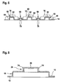
- FIG. 5 From in the representation of the FIG. 1 appropriate FIG. 5 it can be seen that in the intermediate regions between the regions of the carrier foil 12 intended to hold the nonwoven material and the glass mesh, additional carrier projections 60 having substantially planar end walls (or end faces) 62 are formed out.
- the carrier projections 60 have a cylindrical peripheral wall 64 whose height is dimensioned such that the outer side of the end faces 62 are flush in the plane of the end faces 24 of the first projection portions 18 of the projections 16 lie.
- the carrier projections 60 thus additionally support the nonwoven material 30 in the intermediate regions between the projections 16.
- low retaining projections 66 open at the underside of the carrier film are formed, which-as in FIG. 6 can be seen - undercuts 70 for the web or plate material adhesively bonding with substrate hardened or hardened adhesive mortar or adhesive form.
- FIG. 7 and 8th an additional modification of the sections 18 of the projections 16 is shown.
- the subsections 18 have protrusions 72 projecting in the circumferential direction, with end faces 24 which continue to extend essentially parallel to the base surface of the carrier film 12.
- the diameter of the end face 24 is reduced, whereby an additional reinforcement of the projections 16 is achieved in total.
- the total area of the end faces 24, however, is not reduced.
- FIG. 8 illustrated modification consists in that in the formed from the first sections 18 of the base 14 of the carrier film 12 second projection portions 20 are provided in the transition region of the connecting wall portions 26 to their end walls 28 radially projecting from the connecting wall portions projections 74 which a positive anchoring adhesively bonded in the plate coverings with the web or plate material bound or hardened mortar or adhesive layer.
- FIG. 9 and 10 the components and use case of a modified embodiment of the drainage plate material 10 'according to the invention are illustrated, of which only the ones described in connection with FIGS FIGS. 1 to 4 described embodiment, different embodiments are described.
- the plate material 10 'instead of the three-layer structure of the plate covering 10 has a four-layer structure.
- the nonwoven material 30 and the glass mesh fabric 32 occurs here as a fourth layer even in the case illustrated by a pressure-resistant mesh material made of plastic and provided on the underside facing away from the base sheet 12 Abstandshatter layer 50 added.
- the projections 16 are here shown as low single-stage cylindrical projections with closed end face 28, wherein in FIG. 9 through openings in the form of milled from the end face 28 in the projections slots 29 are shown.
- the layer of nonwoven material 30 is arranged in this case on the underside facing the substrate base 12 between the underside and the spacer layer 50, which is thus prevented when creating a plate covering on the top of the occupied with the glass mesh fabric 32 carrier film applied mortar or adhesive can pass through to the top of the subsurface of the pavement structure. Although it is possible to penetrate through the slots in the projections 16 in the cavity formed on the underside of the projections, which also contributes to an additional solid connection of the applied on the hardened mortar layer plate covering.
- the spacer layer 50 is placed non-adhesive on the top of the substrate formed by the concrete support plate, the desired stress decoupling is ensured and at the same time by the grid material of the spacer layer 50 is a capillary-breaking gap between the carrier film 12 and on their Bottom applied layer of nonwoven material 30 and the - occupied in this case, with a sealing layer 52 - top of the concrete base plate 36 made.
Claims (15)
- Elément de voie ou de dallage de drainage (10) pour la pose de dalles d'assèchement et/ou de ventilation (40) dans des zones extérieures exposées à des influences atmosphériques, sur une couche de mortier ou de colle (38) déposée avec une faible épaisseur de couche, comportant une feuille de support (12) en plastique rigide imperméable au liquide avec une face de base plane (14), dans laquelle on a formé une pluralité de saillies (16) avec des parois frontales essentiellement planes (24, 28) formant les fonds des saillies en une répartition régulière ou irrégulière, et avec un élément de grille en verre (32) formant une armature pour la couche de mortier ou de colle (38) fixant les dalles (40) sur l'élément de voie ou de dallage (10), dans lequel les saillies (16), dans leur position de pose normale, sont saillantes vers le dallage à poser (40) en étant orientées en direction opposée au côté inférieur de la face de base (14) de la feuille de support (12) tournée vers le sous-sol et l'élément de grille en verre (32) est prévu sur les côtés plats, situés à l'opposé du sous-sol, des parois frontales (28) des saillies (16), caractérisé en ce que, dans l'espace restant entre les saillies (16) en dessous de l'élément de grille en verre (32) et au-dessus de la face de base plane (14) de la feuille de support (12), il est prévu un élément de non tissé (30) empêchant le passage du mortier ou de la colle encore fluide lors de la pose du dallage.
- Elément de voie ou de dallage selon la revendication 1, caractérisé en ce qu'il est prévu des ouvertures ou des perforations traversantes dans les zones de paroi de liaison (22, 26) des saillies (16) reliant la face de base plane ((14) de la feuille de support (12) aux parois frontales.
- Elément de voie ou de dallage selon la revendication 1 ou 2, caractérisé en ce que les saillies (16) formées dans la face de base plane (14) de la feuille de support (12) présentent chaque fois deux sections partielles étagées (18; 20) se succédant dans la direction de la hauteur, dont la première section partielle (18) se raccordant directement à la face de base (14) de la feuille de support (12) présente une limitation de surface plus grande, vue en plan, que la deuxième section partielle (20) formée dans sa paroi frontale (24) essentiellement parallèle à la face de base (14).
- Elément de voie ou de dallage selon la revendication 3, caractérisé en ce que l'élément de grille en verre (32) est placé sur les côtés plats, situés à l'opposé du sous-sol, des parois frontales (28) des deuxièmes sections partielles (20).
- Elément de voie ou de dallage selon l'une quelconque des revendications 3 ou 4, caractérisé en ce que l'élément de non tissé (30) est réalisé en forme de bande et est pourvu de découpes traversantes et limitées (34), disposées avec la répartition et la limitation extérieure correspondant essentiellement aux deuxièmes sections partielles (20), et est placé sur les côtés plats, situés à l'opposé du sous-sol, des parois frontales (24) des premières sections partielles (18), avant la pose de l'élément de grille en verre (32).
- Elément de voie ou de dallage selon l'une quelconque des revendications 3 à 5, caractérisé en ce que les zones de paroi de liaison (22; 26) des saillies (16) ou des sections partielles (18; 20) sont pourvues de profilages augmentant la résistance à la déformation sous une sollicitation pondérale.
- Elément de voie ou de dallage selon la revendication 6, caractérisé en ce que les profilages sont formés par des nervures ou des ondulations parallèles verticales s'étendant essentiellement sur toute la hauteur des zones de paroi de liaison (22; 26).
- Elément de voie ou de dallage selon la revendication 6, caractérisé en ce que les profilages sont formés par des ergots (72) en saillie sur les premières sections partielles (18) des saillies (16), avec des parois frontales (24) s'étendant essentiellement parallèlement à la face de base de la feuille de support (12).
- Elément de voie ou de dallage selon l'une quelconque des revendications 3 à 8, caractérisé en ce qu'il est prévu des rebords (74) radialement saillants sur les zones de paroi de liaison (26) dans les deuxièmes sections partielles (20) formées dans les première sections partielles (18) réalisées dans la face de base (14) de la feuille de support (12), dans la zone de transition entre leurs zones de paroi de liaison (26) et leurs parois frontales (28).
- Elément de voie ou de dallage selon l'une quelconque des revendications 3 à 9, caractérisé en ce que des saillies de support supplémentaires (60) sont formées dans les zones de la face de base (14) de la feuille de support (12) situées entre les saillies (16), avec des parois frontales essentiellement planes (62), dont la hauteur est dimensionnée de telle manière que les côtés plats supérieurs des parois frontales (62) et des parois frontales (24) des premières sections partielles (18) soient situés essentiellement dans le même plan, s'étendant parallèlement à la face de base (14) de la feuille de support (12).
- Elément de voie ou de dallage selon l'une quelconque des revendications 3 à 10, caractérisé en ce que des saillies supplémentaires basses de maintien (66) ouvertes vers le côté intérieur de la feuille de support sont formées dans les zones de la face de base (14) de la feuille de support (12) situées entre les saillies (16), dont la paroi intérieure est chaque fois pourvue d'au moins un creux, qui forme une contre-dépouille (70) pour la couche de mortier ou de colle durcie ou prise assemblant par adhérence l'élément de voie ou de dallage au sous-sol.
- Elément de voie ou de dallage (10') pour la pose de dalles d'assèchement et/ou de ventilation (40) dans des zones extérieures exposées à des influences atmosphériques, sur une couche de mortier ou de colle (38) déposée avec une faible épaisseur de couche, comportant une feuille de support (12) en plastique rigide imperméable au liquide avec une face de base plane (14), dans laquelle on a formé une pluralité de saillies (16) avec des parois frontales essentiellement planes formant les fonds des saillies (16) en une répartition régulière ou irrégulière, et avec un élément de grille en verre (32) formant une armature pour la couche de mortier ou de colle (38) fixant les dalles (40) sur l'élément de voie ou de dallage (10'), caractérisé en ce que les saillies (16), dans leur position de pose normale, sont saillantes dans la face de base (14) de la feuille de support (12) en direction du sous-sol (36) et l'élément de grille en verre (32) est prévu sur le côté plat, situé à l'opposé du sous-sol, de la face de base (14) de la feuille de support (12), en ce qu'il est prévu des ouvertures ou des perforations ou des fentes traversantes (29) dans les zones de paroi de liaison reliant la face de base plane (14) de la feuille de support (12) aux parois frontales des saillies (16), et en ce qu'une couche d'un élément de non tissé (30) empêchant le passage de mortier ou de colle encore fluide lors de la pose est disposée sur les parois frontales, tournées vers le sous-sol, des saillies (16) de la feuille de support (12).
- Elément de voie ou de dallage selon la revendication 12, caractérisé en ce qu'il est prévu, sur le couche d'élément de non tissé (30) tournée vers le sous-sol, une couche d'écartement (50) maintenant l'élément de voie ou de dallage (10') à une distance au-dessus du sous-sol, dans sa position de pose normale sur le sous-sol.
- Elément de voie ou de dallage selon la revendication 13, caractérisé en ce que la couche d'écartement (50) est formée par un élément de grille, de préférence un élément de grille en plastique.
- Elément de voie ou de dallage selon la revendication 13, caractérisé en ce que la couche d'écartement (50) est formée par une bande de feuille de plastique séparée, pourvue de nervures ou de bosses formées dans une face de base plane.
Priority Applications (1)
| Application Number | Priority Date | Filing Date | Title |
|---|---|---|---|
| PL06706632T PL1846630T3 (pl) | 2005-02-08 | 2006-02-03 | Taśmowy lub płytowy materiał drenażowy do odwadniającego i/lub odpowietrzającego układania wykładzin płytowych w cienkim złożu |
Applications Claiming Priority (2)
| Application Number | Priority Date | Filing Date | Title |
|---|---|---|---|
| DE202005001965U DE202005001965U1 (de) | 2005-02-08 | 2005-02-08 | Drainage-Bahn- oder Plattenmaterial zur entwässernden und/oder entlüftenden Verlegung von Plattenbelägen im Dünnbett |
| PCT/EP2006/000970 WO2006084637A1 (fr) | 2005-02-08 | 2006-02-03 | Element de voie de drainage ou de dallage pour la pose sur couche mince de dalles pour l'assechement ou la ventilation |
Publications (2)
| Publication Number | Publication Date |
|---|---|
| EP1846630A1 EP1846630A1 (fr) | 2007-10-24 |
| EP1846630B1 true EP1846630B1 (fr) | 2009-08-05 |
Family
ID=36643480
Family Applications (1)
| Application Number | Title | Priority Date | Filing Date |
|---|---|---|---|
| EP06706632A Active EP1846630B1 (fr) | 2005-02-08 | 2006-02-03 | Element de voie de drainage ou de dallage pour la pose sur couche mince de dalles pour l'assechement ou la ventilation |
Country Status (7)
| Country | Link |
|---|---|
| EP (1) | EP1846630B1 (fr) |
| AT (1) | ATE438772T1 (fr) |
| DE (2) | DE202005001965U1 (fr) |
| DK (1) | DK1846630T3 (fr) |
| ES (1) | ES2330562T3 (fr) |
| PL (1) | PL1846630T3 (fr) |
| WO (1) | WO2006084637A1 (fr) |
Families Citing this family (11)
| Publication number | Priority date | Publication date | Assignee | Title |
|---|---|---|---|---|
| DE102007042700A1 (de) * | 2007-09-07 | 2009-03-12 | Walter Gutjahr | Verfahren zur Herstellung eines hochbelastbaren Estrichs geringer Schichtdicke sowie Bewehrungsmaterial zur Durchführung des Verfahrens |
| NO333076B1 (no) | 2007-12-05 | 2013-02-25 | Isola As | Filtbelagt knasteplate og anvendelse av denne |
| DE102008045769A1 (de) * | 2008-07-25 | 2010-01-28 | Walter Gutjahr | Verfahren zur Herstellung von Plattenbelägen und Entlüftungs- und/oder Drainagematerial zur Durchführung des Verfahrens |
| DE202009001392U1 (de) * | 2009-02-05 | 2010-06-24 | Gutjahr, Walter | Stützvorrichtung für einen verlegbaren Bodenbelag |
| DE102010048939A1 (de) * | 2010-10-19 | 2012-04-19 | Bernd Griesinger | Luftverteilsystem für Gebäude |
| DE202010012888U1 (de) * | 2010-11-15 | 2012-02-16 | Walter Gutjahr | Stelzlageranordnung für einen unterlüfteten Bodenbelag |
| DE102012203894A1 (de) * | 2012-03-13 | 2013-09-19 | Henkel Ag & Co. Kgaa | Baubereichsbahn |
| DE102013102640A1 (de) | 2013-03-14 | 2014-09-18 | Sandro Thronicke | Drainagematte |
| DE102013102607A1 (de) | 2013-03-14 | 2014-09-18 | Sandro Thronicke | Drainagematte zur entwässernden und/oder entlüftenden Verlegung von Oberflächenkonstruktionen |
| EP2837752B1 (fr) * | 2013-08-13 | 2019-10-09 | Technische Hochshule Mittelhessen | Système de sol et procédé de fabrication associé |
| US8955278B1 (en) * | 2014-05-16 | 2015-02-17 | Hilton R. Mills | Subfloor drainage panel |
Family Cites Families (15)
| Publication number | Priority date | Publication date | Assignee | Title |
|---|---|---|---|---|
| DE3310013A1 (de) * | 1983-03-19 | 1984-09-27 | Drefahl, Jens, Ing.(grad.), 6458 Rodenbach | Aus filter-, draen- und waermedaemmschicht bestehender verbundaufbau |
| DE9011271U1 (fr) * | 1989-08-30 | 1990-10-04 | Deitermann Chemiewerk Gmbh & Co Kg, 4354 Datteln, De | |
| DE4003875A1 (de) * | 1990-02-09 | 1991-08-14 | Walter Gutjahr | Drain-daemm- und dichtplatten |
| DE4004901C2 (de) * | 1990-02-16 | 2001-04-19 | Walter Gutjahr | Kunststoffprofil-Drainagebahn |
| DE4241229A1 (de) * | 1992-12-08 | 1994-06-09 | Walter Gutjahr | Kapillarbrechende Rollenbahndrainage |
| DE29622129U1 (de) * | 1996-12-21 | 1997-04-30 | Gefinex Gmbh | Neue Estrichunterlage |
| DK0893553T3 (da) * | 1997-07-24 | 2002-06-24 | Walter Gutjahr | Profilbane til udluftning og afvanding af gulvfliser, især keramiske fliser, som er lagt i tyndt leje |
| DE19750277A1 (de) * | 1997-11-13 | 1999-05-20 | Walter Gutjahr | Trägerbahn für Witterungseinflüssen ausgesetzte Boden- oder Wandbeläge |
| DE19834439A1 (de) * | 1998-07-30 | 1999-03-25 | Baumjohann Adolf | Drainelement zur Drainierung und zur Be- und Entlüftung von Balkonen, Terrassen und begeh- oder befahrbaren Außenflächen |
| ES2222757T3 (es) * | 1999-01-15 | 2005-02-01 | Walter Gutjahr | Banda de drenaje. |
| DE29915866U1 (de) * | 1999-01-15 | 2000-05-31 | Gutjahr Walter | Drainagebahn |
| ATE280287T1 (de) * | 1999-09-11 | 2004-11-15 | Walter Gutjahr | Verlegehilfe für die erstellung von aufgestelzten oder unterlüfteten platten-belägen |
| DE20020316U1 (de) * | 2000-10-24 | 2002-03-07 | Gutjahr Walter | Schalldämmende Trägerbahn für Bodenbeläge, insbesondere Plattenbeläge |
| DE10060751C1 (de) * | 2000-12-07 | 2002-09-05 | Koester Bauchemie Gmbh | Abdichtungs- und Drainagesystem sowie dessen Verwendung |
| WO2004018789A1 (fr) * | 2002-08-17 | 2004-03-04 | Walter Gutjahr | Procede de production de surfaces exterieures de batiments et materiau en bande ou en plaque necessaire a la mise en oeuvre de ce procede |
-
2005
- 2005-02-08 DE DE202005001965U patent/DE202005001965U1/de not_active Expired - Lifetime
-
2006
- 2006-02-03 DE DE502006004440T patent/DE502006004440D1/de active Active
- 2006-02-03 DK DK06706632T patent/DK1846630T3/da active
- 2006-02-03 PL PL06706632T patent/PL1846630T3/pl unknown
- 2006-02-03 WO PCT/EP2006/000970 patent/WO2006084637A1/fr active Application Filing
- 2006-02-03 EP EP06706632A patent/EP1846630B1/fr active Active
- 2006-02-03 AT AT06706632T patent/ATE438772T1/de active
- 2006-02-03 ES ES06706632T patent/ES2330562T3/es active Active
Also Published As
| Publication number | Publication date |
|---|---|
| ATE438772T1 (de) | 2009-08-15 |
| ES2330562T3 (es) | 2009-12-11 |
| DE202005001965U1 (de) | 2006-06-14 |
| PL1846630T3 (pl) | 2009-12-31 |
| WO2006084637A1 (fr) | 2006-08-17 |
| EP1846630A1 (fr) | 2007-10-24 |
| DE502006004440D1 (de) | 2009-09-17 |
| DK1846630T3 (da) | 2009-12-14 |
Similar Documents
| Publication | Publication Date | Title |
|---|---|---|
| EP1846630B1 (fr) | Element de voie de drainage ou de dallage pour la pose sur couche mince de dalles pour l'assechement ou la ventilation | |
| EP1030954B1 (fr) | Bande support pour revetements de sol ou revetements muraux exposes aux intemperies | |
| EP3128103B1 (fr) | Tapis de desolidarisation | |
| EP0879331A1 (fr) | Structure de sol composite | |
| EP1462727B1 (fr) | Dispositif pour la pose de tubes traversés par des fluides réfrigérants ou chauffants d'un système de conditionnement thermique à grande surface | |
| EP1697600B1 (fr) | Systeme multicouche de desolidarisation, d'etancheification et de drainage | |
| EP1375780A1 (fr) | Matériau en matière plastique en forme de feuille ou plaque pour supporter des dalles ou carrelages | |
| EP1762668A2 (fr) | Matériau de drainage pour le drainage de couvertures de marches d'escaliers | |
| EP1083269B1 (fr) | Aides pour la pose de revêtements en plaques en position surélevée ou ventilée | |
| EP3075908A1 (fr) | Rainure de fente | |
| EP1918484A2 (fr) | Système de découplage et de drainage multicouche | |
| EP2148022B1 (fr) | Procédé de fabrication de revêtements de plaque et de matériaux d'aération et/ou de drainage pour l'exécution du procédé | |
| DE10055354B4 (de) | Plattenelement | |
| DE102004026651B4 (de) | Mehrschichtiges Entkopplungs-, Abdichtungs- und Drainagesystem | |
| EP2757195B1 (fr) | Elément de construction routière pour étanchéifier des joints et son utilisation | |
| EP1347115B1 (fr) | Procédé pour la construction des dalles drainées de faible hauteur pour balcons et terrasses et un tel assemblage des dalles | |
| DE10252539B3 (de) | Noppenbahn zum Abdichten von Bauwerken | |
| EP1609927A2 (fr) | Carreau pour revêtement de sol | |
| DE1484027C (fr) | ||
| DE102005006222A1 (de) | Fugenband | |
| DE102005001262A1 (de) | Bodenaufbau, insbesondere für Gebäude | |
| EP1582655A2 (fr) | Bande isolante d'extrémité composite pour la pose de dalles inférieures en béton | |
| DE10302522A1 (de) | Verfahren zur Erstellung von drainierten Plattenbelägen mit geringer Aufbauhöhe auf Balkon- oder Terrassenflächen sowie drainierte Plattenbelaganordnung geringerer Aufbauhöhe auf Balkon- oder Terrassenflächen | |
| DE102017102861A1 (de) | Gründung aus Schaumglasschotter und Porenbeton | |
| DE3129834A1 (de) | Vorrichtung zur erstellung witterungsbestaendiger bodenbelaege von balkons, terrassen oder dgl. |
Legal Events
| Date | Code | Title | Description |
|---|---|---|---|
| PUAI | Public reference made under article 153(3) epc to a published international application that has entered the european phase |
Free format text: ORIGINAL CODE: 0009012 |
|
| 17P | Request for examination filed |
Effective date: 20070622 |
|
| AK | Designated contracting states |
Kind code of ref document: A1 Designated state(s): AT BE BG CH CY CZ DE DK EE ES FI FR GB GR HU IE IS IT LI LT LU LV MC NL PL PT RO SE SI SK TR |
|
| 17Q | First examination report despatched |
Effective date: 20071220 |
|
| DAX | Request for extension of the european patent (deleted) | ||
| GRAP | Despatch of communication of intention to grant a patent |
Free format text: ORIGINAL CODE: EPIDOSNIGR1 |
|
| GRAS | Grant fee paid |
Free format text: ORIGINAL CODE: EPIDOSNIGR3 |
|
| GRAA | (expected) grant |
Free format text: ORIGINAL CODE: 0009210 |
|
| AK | Designated contracting states |
Kind code of ref document: B1 Designated state(s): AT BE BG CH CY CZ DE DK EE ES FI FR GB GR HU IE IS IT LI LT LU LV MC NL PL PT RO SE SI SK TR |
|
| REG | Reference to a national code |
Ref country code: GB Ref legal event code: FG4D Free format text: NOT ENGLISH |
|
| REG | Reference to a national code |
Ref country code: CH Ref legal event code: EP |
|
| REG | Reference to a national code |
Ref country code: IE Ref legal event code: FG4D |
|
| REF | Corresponds to: |
Ref document number: 502006004440 Country of ref document: DE Date of ref document: 20090917 Kind code of ref document: P |
|
| REG | Reference to a national code |
Ref country code: CH Ref legal event code: NV Representative=s name: BOVARD AG PATENTANWAELTE |
|
| REG | Reference to a national code |
Ref country code: SE Ref legal event code: TRGR |
|
| REG | Reference to a national code |
Ref country code: ES Ref legal event code: FG2A Ref document number: 2330562 Country of ref document: ES Kind code of ref document: T3 |
|
| REG | Reference to a national code |
Ref country code: DK Ref legal event code: T3 |
|
| REG | Reference to a national code |
Ref country code: PL Ref legal event code: T3 |
|
| LTIE | Lt: invalidation of european patent or patent extension |
Effective date: 20090805 |
|
| PG25 | Lapsed in a contracting state [announced via postgrant information from national office to epo] |
Ref country code: IS Free format text: LAPSE BECAUSE OF FAILURE TO SUBMIT A TRANSLATION OF THE DESCRIPTION OR TO PAY THE FEE WITHIN THE PRESCRIBED TIME-LIMIT Effective date: 20091205 Ref country code: LT Free format text: LAPSE BECAUSE OF FAILURE TO SUBMIT A TRANSLATION OF THE DESCRIPTION OR TO PAY THE FEE WITHIN THE PRESCRIBED TIME-LIMIT Effective date: 20090805 Ref country code: FI Free format text: LAPSE BECAUSE OF FAILURE TO SUBMIT A TRANSLATION OF THE DESCRIPTION OR TO PAY THE FEE WITHIN THE PRESCRIBED TIME-LIMIT Effective date: 20090805 |
|
| PG25 | Lapsed in a contracting state [announced via postgrant information from national office to epo] |
Ref country code: LV Free format text: LAPSE BECAUSE OF FAILURE TO SUBMIT A TRANSLATION OF THE DESCRIPTION OR TO PAY THE FEE WITHIN THE PRESCRIBED TIME-LIMIT Effective date: 20090805 Ref country code: SI Free format text: LAPSE BECAUSE OF FAILURE TO SUBMIT A TRANSLATION OF THE DESCRIPTION OR TO PAY THE FEE WITHIN THE PRESCRIBED TIME-LIMIT Effective date: 20090805 |
|
| REG | Reference to a national code |
Ref country code: IE Ref legal event code: FD4D |
|
| PG25 | Lapsed in a contracting state [announced via postgrant information from national office to epo] |
Ref country code: PT Free format text: LAPSE BECAUSE OF FAILURE TO SUBMIT A TRANSLATION OF THE DESCRIPTION OR TO PAY THE FEE WITHIN THE PRESCRIBED TIME-LIMIT Effective date: 20091205 Ref country code: BG Free format text: LAPSE BECAUSE OF FAILURE TO SUBMIT A TRANSLATION OF THE DESCRIPTION OR TO PAY THE FEE WITHIN THE PRESCRIBED TIME-LIMIT Effective date: 20091105 |
|
| PG25 | Lapsed in a contracting state [announced via postgrant information from national office to epo] |
Ref country code: RO Free format text: LAPSE BECAUSE OF FAILURE TO SUBMIT A TRANSLATION OF THE DESCRIPTION OR TO PAY THE FEE WITHIN THE PRESCRIBED TIME-LIMIT Effective date: 20090805 Ref country code: IE Free format text: LAPSE BECAUSE OF FAILURE TO SUBMIT A TRANSLATION OF THE DESCRIPTION OR TO PAY THE FEE WITHIN THE PRESCRIBED TIME-LIMIT Effective date: 20090805 Ref country code: EE Free format text: LAPSE BECAUSE OF FAILURE TO SUBMIT A TRANSLATION OF THE DESCRIPTION OR TO PAY THE FEE WITHIN THE PRESCRIBED TIME-LIMIT Effective date: 20090805 Ref country code: CZ Free format text: LAPSE BECAUSE OF FAILURE TO SUBMIT A TRANSLATION OF THE DESCRIPTION OR TO PAY THE FEE WITHIN THE PRESCRIBED TIME-LIMIT Effective date: 20090805 |
|
| PG25 | Lapsed in a contracting state [announced via postgrant information from national office to epo] |
Ref country code: SK Free format text: LAPSE BECAUSE OF FAILURE TO SUBMIT A TRANSLATION OF THE DESCRIPTION OR TO PAY THE FEE WITHIN THE PRESCRIBED TIME-LIMIT Effective date: 20090805 |
|
| PLBE | No opposition filed within time limit |
Free format text: ORIGINAL CODE: 0009261 |
|
| STAA | Information on the status of an ep patent application or granted ep patent |
Free format text: STATUS: NO OPPOSITION FILED WITHIN TIME LIMIT |
|
| 26N | No opposition filed |
Effective date: 20100507 |
|
| PG25 | Lapsed in a contracting state [announced via postgrant information from national office to epo] |
Ref country code: MC Free format text: LAPSE BECAUSE OF NON-PAYMENT OF DUE FEES Effective date: 20100301 Ref country code: GR Free format text: LAPSE BECAUSE OF FAILURE TO SUBMIT A TRANSLATION OF THE DESCRIPTION OR TO PAY THE FEE WITHIN THE PRESCRIBED TIME-LIMIT Effective date: 20091106 |
|
| REG | Reference to a national code |
Ref country code: CH Ref legal event code: PFA Owner name: GUTJAHR, WALTER Free format text: GUTJAHR, WALTER#PHILIPP-REIS-STRASSE 5-7#64404 BICKENBACH (DE) -TRANSFER TO- GUTJAHR, WALTER#PHILIPP-REIS-STRASSE 5-7#64404 BICKENBACH (DE) |
|
| PG25 | Lapsed in a contracting state [announced via postgrant information from national office to epo] |
Ref country code: CY Free format text: LAPSE BECAUSE OF FAILURE TO SUBMIT A TRANSLATION OF THE DESCRIPTION OR TO PAY THE FEE WITHIN THE PRESCRIBED TIME-LIMIT Effective date: 20090805 |
|
| PG25 | Lapsed in a contracting state [announced via postgrant information from national office to epo] |
Ref country code: LU Free format text: LAPSE BECAUSE OF NON-PAYMENT OF DUE FEES Effective date: 20100203 Ref country code: HU Free format text: LAPSE BECAUSE OF FAILURE TO SUBMIT A TRANSLATION OF THE DESCRIPTION OR TO PAY THE FEE WITHIN THE PRESCRIBED TIME-LIMIT Effective date: 20100206 |
|
| PG25 | Lapsed in a contracting state [announced via postgrant information from national office to epo] |
Ref country code: TR Free format text: LAPSE BECAUSE OF FAILURE TO SUBMIT A TRANSLATION OF THE DESCRIPTION OR TO PAY THE FEE WITHIN THE PRESCRIBED TIME-LIMIT Effective date: 20090805 |
|
| REG | Reference to a national code |
Ref country code: FR Ref legal event code: PLFP Year of fee payment: 10 |
|
| REG | Reference to a national code |
Ref country code: CH Ref legal event code: PUE Owner name: ARDEX ANLAGEN GMBH, DE Free format text: FORMER OWNER: GUTJAHR, WALTER, DE |
|
| REG | Reference to a national code |
Ref country code: DE Ref legal event code: R082 Ref document number: 502006004440 Country of ref document: DE Representative=s name: PATENTANWAELTE KATSCHER HABERMANN, DE Ref country code: DE Ref legal event code: R081 Ref document number: 502006004440 Country of ref document: DE Owner name: ARDEX ANLAGEN GMBH, DE Free format text: FORMER OWNER: GUTJAHR, WALTER, 64404 BICKENBACH, DE |
|
| REG | Reference to a national code |
Ref country code: ES Ref legal event code: PC2A Owner name: ARDEX ANLAGEN GMBH Effective date: 20151002 |
|
| REG | Reference to a national code |
Ref country code: FR Ref legal event code: PLFP Year of fee payment: 11 |
|
| REG | Reference to a national code |
Ref country code: NL Ref legal event code: PD Owner name: ARDEX ANLAGEN GMBH; DE Free format text: DETAILS ASSIGNMENT: VERANDERING VAN EIGENAAR(S), OVERDRACHT; FORMER OWNER NAME: WALTER GUTJAHR Effective date: 20151022 |
|
| REG | Reference to a national code |
Ref country code: FR Ref legal event code: TP Owner name: ARDEX ANLAGEN GMBH, DE Effective date: 20160224 |
|
| PGFP | Annual fee paid to national office [announced via postgrant information from national office to epo] |
Ref country code: DK Payment date: 20160222 Year of fee payment: 11 Ref country code: ES Payment date: 20160223 Year of fee payment: 11 |
|
| PGFP | Annual fee paid to national office [announced via postgrant information from national office to epo] |
Ref country code: PL Payment date: 20160125 Year of fee payment: 11 |
|
| REG | Reference to a national code |
Ref country code: FR Ref legal event code: PLFP Year of fee payment: 12 |
|
| REG | Reference to a national code |
Ref country code: AT Ref legal event code: PC Ref document number: 438772 Country of ref document: AT Kind code of ref document: T Owner name: ARDEX ANLAGEN GMBH, DE Effective date: 20170202 |
|
| REG | Reference to a national code |
Ref country code: GB Ref legal event code: 732E Free format text: REGISTERED BETWEEN 20170324 AND 20170330 |
|
| REG | Reference to a national code |
Ref country code: DK Ref legal event code: EBP Effective date: 20170228 |
|
| PG25 | Lapsed in a contracting state [announced via postgrant information from national office to epo] |
Ref country code: DK Free format text: LAPSE BECAUSE OF NON-PAYMENT OF DUE FEES Effective date: 20170228 |
|
| REG | Reference to a national code |
Ref country code: FR Ref legal event code: PLFP Year of fee payment: 13 |
|
| PGFP | Annual fee paid to national office [announced via postgrant information from national office to epo] |
Ref country code: SE Payment date: 20180222 Year of fee payment: 13 |
|
| REG | Reference to a national code |
Ref country code: ES Ref legal event code: FD2A Effective date: 20180629 |
|
| PG25 | Lapsed in a contracting state [announced via postgrant information from national office to epo] |
Ref country code: ES Free format text: LAPSE BECAUSE OF NON-PAYMENT OF DUE FEES Effective date: 20170204 |
|
| PG25 | Lapsed in a contracting state [announced via postgrant information from national office to epo] |
Ref country code: PL Free format text: LAPSE BECAUSE OF NON-PAYMENT OF DUE FEES Effective date: 20170203 |
|
| REG | Reference to a national code |
Ref country code: SE Ref legal event code: EUG |
|
| PG25 | Lapsed in a contracting state [announced via postgrant information from national office to epo] |
Ref country code: SE Free format text: LAPSE BECAUSE OF NON-PAYMENT OF DUE FEES Effective date: 20190204 |
|
| PGFP | Annual fee paid to national office [announced via postgrant information from national office to epo] |
Ref country code: CH Payment date: 20210222 Year of fee payment: 16 Ref country code: FR Payment date: 20210218 Year of fee payment: 16 Ref country code: IT Payment date: 20210226 Year of fee payment: 16 Ref country code: NL Payment date: 20210218 Year of fee payment: 16 |
|
| PGFP | Annual fee paid to national office [announced via postgrant information from national office to epo] |
Ref country code: BE Payment date: 20210218 Year of fee payment: 16 Ref country code: GB Payment date: 20210222 Year of fee payment: 16 |
|
| REG | Reference to a national code |
Ref country code: NL Ref legal event code: MM Effective date: 20220301 |
|
| REG | Reference to a national code |
Ref country code: CH Ref legal event code: PL |
|
| REG | Reference to a national code |
Ref country code: BE Ref legal event code: MM Effective date: 20220228 |
|
| GBPC | Gb: european patent ceased through non-payment of renewal fee |
Effective date: 20220203 |
|
| PG25 | Lapsed in a contracting state [announced via postgrant information from national office to epo] |
Ref country code: NL Free format text: LAPSE BECAUSE OF NON-PAYMENT OF DUE FEES Effective date: 20220301 Ref country code: FR Free format text: LAPSE BECAUSE OF NON-PAYMENT OF DUE FEES Effective date: 20220228 |
|
| PG25 | Lapsed in a contracting state [announced via postgrant information from national office to epo] |
Ref country code: LI Free format text: LAPSE BECAUSE OF NON-PAYMENT OF DUE FEES Effective date: 20220228 Ref country code: GB Free format text: LAPSE BECAUSE OF NON-PAYMENT OF DUE FEES Effective date: 20220203 Ref country code: CH Free format text: LAPSE BECAUSE OF NON-PAYMENT OF DUE FEES Effective date: 20220228 |
|
| PG25 | Lapsed in a contracting state [announced via postgrant information from national office to epo] |
Ref country code: BE Free format text: LAPSE BECAUSE OF NON-PAYMENT OF DUE FEES Effective date: 20220228 |
|
| PGFP | Annual fee paid to national office [announced via postgrant information from national office to epo] |
Ref country code: AT Payment date: 20230215 Year of fee payment: 18 |
|
| PG25 | Lapsed in a contracting state [announced via postgrant information from national office to epo] |
Ref country code: IT Free format text: LAPSE BECAUSE OF NON-PAYMENT OF DUE FEES Effective date: 20220203 |
|
| PGFP | Annual fee paid to national office [announced via postgrant information from national office to epo] |
Ref country code: AT Payment date: 20240216 Year of fee payment: 19 |
|
| PGFP | Annual fee paid to national office [announced via postgrant information from national office to epo] |
Ref country code: DE Payment date: 20231030 Year of fee payment: 19 |