EP1844509B1 - Multi-layer fuel cell diffuser - Google Patents
Multi-layer fuel cell diffuser Download PDFInfo
- Publication number
- EP1844509B1 EP1844509B1 EP06701351.6A EP06701351A EP1844509B1 EP 1844509 B1 EP1844509 B1 EP 1844509B1 EP 06701351 A EP06701351 A EP 06701351A EP 1844509 B1 EP1844509 B1 EP 1844509B1
- Authority
- EP
- European Patent Office
- Prior art keywords
- layer
- fluid flow
- fuel cell
- mea
- diffusion structure
- Prior art date
- Legal status (The legal status is an assumption and is not a legal conclusion. Google has not performed a legal analysis and makes no representation as to the accuracy of the status listed.)
- Expired - Lifetime
Links
Images


Classifications
-
- H—ELECTRICITY
- H01—ELECTRIC ELEMENTS
- H01M—PROCESSES OR MEANS, e.g. BATTERIES, FOR THE DIRECT CONVERSION OF CHEMICAL ENERGY INTO ELECTRICAL ENERGY
- H01M4/00—Electrodes
- H01M4/86—Inert electrodes with catalytic activity, e.g. for fuel cells
-
- H—ELECTRICITY
- H01—ELECTRIC ELEMENTS
- H01M—PROCESSES OR MEANS, e.g. BATTERIES, FOR THE DIRECT CONVERSION OF CHEMICAL ENERGY INTO ELECTRICAL ENERGY
- H01M8/00—Fuel cells; Manufacture thereof
- H01M8/02—Details
- H01M8/0202—Collectors; Separators, e.g. bipolar separators; Interconnectors
- H01M8/023—Porous and characterised by the material
- H01M8/0241—Composites
- H01M8/0245—Composites in the form of layered or coated products
-
- H—ELECTRICITY
- H01—ELECTRIC ELEMENTS
- H01M—PROCESSES OR MEANS, e.g. BATTERIES, FOR THE DIRECT CONVERSION OF CHEMICAL ENERGY INTO ELECTRICAL ENERGY
- H01M8/00—Fuel cells; Manufacture thereof
- H01M8/10—Fuel cells with solid electrolytes
- H01M8/1016—Fuel cells with solid electrolytes characterised by the electrolyte material
- H01M8/1018—Polymeric electrolyte materials
-
- H—ELECTRICITY
- H01—ELECTRIC ELEMENTS
- H01M—PROCESSES OR MEANS, e.g. BATTERIES, FOR THE DIRECT CONVERSION OF CHEMICAL ENERGY INTO ELECTRICAL ENERGY
- H01M4/00—Electrodes
- H01M4/86—Inert electrodes with catalytic activity, e.g. for fuel cells
- H01M4/8605—Porous electrodes
-
- H—ELECTRICITY
- H01—ELECTRIC ELEMENTS
- H01M—PROCESSES OR MEANS, e.g. BATTERIES, FOR THE DIRECT CONVERSION OF CHEMICAL ENERGY INTO ELECTRICAL ENERGY
- H01M4/00—Electrodes
- H01M4/86—Inert electrodes with catalytic activity, e.g. for fuel cells
- H01M4/8636—Inert electrodes with catalytic activity, e.g. for fuel cells with a gradient in another property than porosity
-
- H—ELECTRICITY
- H01—ELECTRIC ELEMENTS
- H01M—PROCESSES OR MEANS, e.g. BATTERIES, FOR THE DIRECT CONVERSION OF CHEMICAL ENERGY INTO ELECTRICAL ENERGY
- H01M4/00—Electrodes
- H01M4/86—Inert electrodes with catalytic activity, e.g. for fuel cells
- H01M4/8647—Inert electrodes with catalytic activity, e.g. for fuel cells consisting of more than one material, e.g. consisting of composites
- H01M4/8652—Inert electrodes with catalytic activity, e.g. for fuel cells consisting of more than one material, e.g. consisting of composites as mixture
-
- H—ELECTRICITY
- H01—ELECTRIC ELEMENTS
- H01M—PROCESSES OR MEANS, e.g. BATTERIES, FOR THE DIRECT CONVERSION OF CHEMICAL ENERGY INTO ELECTRICAL ENERGY
- H01M4/00—Electrodes
- H01M4/86—Inert electrodes with catalytic activity, e.g. for fuel cells
- H01M4/8647—Inert electrodes with catalytic activity, e.g. for fuel cells consisting of more than one material, e.g. consisting of composites
- H01M4/8657—Inert electrodes with catalytic activity, e.g. for fuel cells consisting of more than one material, e.g. consisting of composites layered
-
- H—ELECTRICITY
- H01—ELECTRIC ELEMENTS
- H01M—PROCESSES OR MEANS, e.g. BATTERIES, FOR THE DIRECT CONVERSION OF CHEMICAL ENERGY INTO ELECTRICAL ENERGY
- H01M8/00—Fuel cells; Manufacture thereof
- H01M8/02—Details
-
- H—ELECTRICITY
- H01—ELECTRIC ELEMENTS
- H01M—PROCESSES OR MEANS, e.g. BATTERIES, FOR THE DIRECT CONVERSION OF CHEMICAL ENERGY INTO ELECTRICAL ENERGY
- H01M8/00—Fuel cells; Manufacture thereof
- H01M8/02—Details
- H01M8/0202—Collectors; Separators, e.g. bipolar separators; Interconnectors
- H01M8/023—Porous and characterised by the material
- H01M8/0234—Carbonaceous material
-
- H—ELECTRICITY
- H01—ELECTRIC ELEMENTS
- H01M—PROCESSES OR MEANS, e.g. BATTERIES, FOR THE DIRECT CONVERSION OF CHEMICAL ENERGY INTO ELECTRICAL ENERGY
- H01M8/00—Fuel cells; Manufacture thereof
- H01M8/02—Details
- H01M8/0202—Collectors; Separators, e.g. bipolar separators; Interconnectors
- H01M8/023—Porous and characterised by the material
- H01M8/0239—Organic resins; Organic polymers
-
- H—ELECTRICITY
- H01—ELECTRIC ELEMENTS
- H01M—PROCESSES OR MEANS, e.g. BATTERIES, FOR THE DIRECT CONVERSION OF CHEMICAL ENERGY INTO ELECTRICAL ENERGY
- H01M8/00—Fuel cells; Manufacture thereof
- H01M8/02—Details
- H01M8/0202—Collectors; Separators, e.g. bipolar separators; Interconnectors
- H01M8/023—Porous and characterised by the material
- H01M8/0241—Composites
- H01M8/0243—Composites in the form of mixtures
-
- H—ELECTRICITY
- H01—ELECTRIC ELEMENTS
- H01M—PROCESSES OR MEANS, e.g. BATTERIES, FOR THE DIRECT CONVERSION OF CHEMICAL ENERGY INTO ELECTRICAL ENERGY
- H01M8/00—Fuel cells; Manufacture thereof
- H01M8/10—Fuel cells with solid electrolytes
-
- H—ELECTRICITY
- H01—ELECTRIC ELEMENTS
- H01M—PROCESSES OR MEANS, e.g. BATTERIES, FOR THE DIRECT CONVERSION OF CHEMICAL ENERGY INTO ELECTRICAL ENERGY
- H01M8/00—Fuel cells; Manufacture thereof
- H01M8/10—Fuel cells with solid electrolytes
- H01M8/1004—Fuel cells with solid electrolytes characterised by membrane-electrode assemblies [MEA]
-
- Y—GENERAL TAGGING OF NEW TECHNOLOGICAL DEVELOPMENTS; GENERAL TAGGING OF CROSS-SECTIONAL TECHNOLOGIES SPANNING OVER SEVERAL SECTIONS OF THE IPC; TECHNICAL SUBJECTS COVERED BY FORMER USPC CROSS-REFERENCE ART COLLECTIONS [XRACs] AND DIGESTS
- Y02—TECHNOLOGIES OR APPLICATIONS FOR MITIGATION OR ADAPTATION AGAINST CLIMATE CHANGE
- Y02E—REDUCTION OF GREENHOUSE GAS [GHG] EMISSIONS, RELATED TO ENERGY GENERATION, TRANSMISSION OR DISTRIBUTION
- Y02E60/00—Enabling technologies; Technologies with a potential or indirect contribution to GHG emissions mitigation
- Y02E60/30—Hydrogen technology
- Y02E60/50—Fuel cells
Definitions
- the present invention relates to fuel cells and in particular to proton-exchange membrane type fuel cells in which hydrogen is supplied to the anode side of the fuel cell, oxygen is supplied to the cathode side of the fuel cell and water byproduct is produced at and removed from the cathode side of the fuel cell.
- Such fuel cells comprise a proton exchange membrane (PEM) sandwiched between two porous electrodes, together comprising a membrane-electrode assembly (MEA).
- the MEA itself is conventionally sandwiched between: (i) a cathode diffusion structure having a first face adjacent to the cathode face of the MEA and (ii) an anode diffusion structure having a first face adjacent the anode face of the MEA.
- the second face of the anode diffusion structure contacts an anode fluid flow field plate for current collection and for distributing hydrogen to the second face of the anode diffusion structure.
- the second face of the cathode diffusion structure contacts a cathode fluid flow field plate for current collection, for distributing oxygen to the second face of the cathode diffusion structure, and for extracting excess water from the MEA.
- the anode and cathode fluid flow field plates conventionally each comprise a rigid, electrically conductive material having fluid flow channels in the surface adjacent the respective diffusion structure for delivery of the fuel gases (e.g. hydrogen and oxygen) and removal of the exhaust gases (e.g. unused oxygen and water vapour).
- the prior art has recognised a number of ways of improving the action of the diffusion structures.
- US 6,605,381 teaches a diffusion structure between a fluid flow field plate and the MEA surface, the diffusion structure having a gradient in gas permeability in the direction perpendicular to the MEA.
- the diffusion structure comprises a laminated or continuously variable medium with higher gas permeability closer to the MEA than at the fluid flow field plate. In this way, water balance at the MEA is maintained more uniform across the area of the MEA.
- US 6,350,539 teaches a multi-layer cathode diffusion structure between a fluid flow field plate and the MEA surface in which the diffusion structure has: (i) an absorption layer adjacent to the MEA of relatively low hydrophobicity to encourage absorption of water from the MEA, (ii) a bulk layer of intermediate hydrophobicity and (iii) a desorption layer of relatively high hydrophobicity adjacent to the fluid flow field plate to encourage desorption of water from the diffusion structure into the fluid flow field plate. In this way, water transfer from the MEA to the exhaust is encouraged.
- WO 03/038924 describes a diffusion structure having porosity which varies as a function of certain trigger conditions such as temperature. In this way, the development of a hot spot in the cell from non-uniform distribution of fuel and/or water in the cell triggers a change in porosity acting against the change.
- US 6,451,470 describes a diffusion structure in which a layer of the diffusion material is provided with a filling material through a part of its thickness that inhibits the diffusion constant of water through the structure while maintaining a sufficient diffusion constant for oxygen, thereby ensuring an adequate supply of reactant oxygen at the same time as presenting over-transport of water from the MEA.
- JP 2004039416 describes a fuel cell with a hydrophilic layer adjacent an oxidizer electrode side separator and a hydrophobic layer adjacent an oxidiser electrode of a membrane-electrode assembly.
- the hydrophobic layer is formed by roughening the surface of a base material.
- EP 0928036 describes a fuel cell gas diffusion electrode with a hydrophobic layer positioned adjacent a feedgas plenum and a hydrophilic layer adjacent a membrane electrode assembly.
- the prior art generally proposes the use of hydrophobic diffusion media or, in the case of US '539, variable hydrophobicity with a high hydrophobicity at at least the interface with the cathode fluid flow field plate to encourage desorption into the fluid flow channels.
- porous carbon fuel cell diffusion materials are treated with PTFE or a similar hydrophobic substance to enhance the removal of water from the catalyst layer of the electrode.
- PTFE a similar hydrophobic substance
- this actually encourages the formation of large water droplets in the diffusion material adjacent or near to the cathode fluid flow field plate.
- the formation of large droplets of product water in or adjacent to the cathode fluid flow channels can be detrimental to the performance of the fuel cell.
- the cathode fluid flow field plates are not open to ambient air and the pressure drop between the compressed air or oxygen inlet and the exit (exhaust) will be significantly raised by the presence of water droplets, resulting in higher associated parasitic energy losses for the system.
- the cathode fluid flow field plates are open to ambient air, usually assisted by a low pressure air source such as an axial or centrifugal fan which provides the dual function of stack cooling and oxygen supply. In this configuration, formation of water droplets in the cathode diffusion structure and fluid flow plate channels may eventually result in a complete blockade of the channels with oxygen transport being restricted to the adjacent electrode areas.
- Another problem associated with diffusion structures results from the very high compaction loads applied to the layers of the fuel cell when forming a fuel cell stack comprising a plurality of serially connected cells.
- the various layers of a fuel cell stack are compressed together under high load.
- distinct areas of compression of the diffusion structure are concentrated in the region of the 'lands' or 'ribs' between channels in the surface of the cathode fluid flow field plates. This localised compression has been found to locally degrade the diffusion coefficient of the diffusion structure between channels thereby compromising the ability to ensure adequate water diffusion to the channels in the fluid flow field plate.
- the present invention provides an electrochemical fuel cell according to claim 1. Described herein is an electrochemical fuel cell comprising:
- an electrochemical fuel cell comprising:
- Figure 1 illustrates a cross-sectional view of part of the cathode side of a fuel cell, including a fluid flow field plate 10 incorporating a plurality of fluid flow channels or conduits 11 for delivery of oxidant to, and extraction of water from, an MEA 12 via a diffusion structure 15.
- the diffusion structure must be sufficiently porous and penneable to ensure adequate transport of oxygen from the channels 11 of the fluid flow field plate 10 to the MEA 12, and to ensure adequate transport of water from the MEA 12 to the channels 11 of the fluid flow field plate 10.
- the water transport must not be so effective that the MEA 12 is allowed to dry out.
- the transport of fluids to and from the MEA 12 should ideally be effective across the entire surface area of the MEA 12.
- a number of problems with existing diffusion structures 15 have been identified. As mentioned earlier, high compression loads applied to the fuel cell stack result in undesirable compression of the diffusion structure 15 in the vicinity of the ribs 13 of the fluid flow plate 10 between the channels 11. This compression of the diffusion structure 15 results in reduced diffusion coefficient for water and/or oxygen in the compressed or compacted portions 16 and therefore relatively higher diffusion coefficient in the relatively uncompressed regions 17. It will therefore be recognised that this can result in irregular hydration of the MEA 12 and irregular gas transport conditions across the surface of the MEA such that performance is compromised or at least not optimised over the entire surface.
- a multilayer diffusion structure 20 is used to provide a number of advantageous features.
- the diffusion structure 20 comprises a four layer structure, the layers having differing properties.
- the diffusion structure 20 has a first face 21 that is in contact with or adjacent to the fluid flow field plate 10 and a second face 22 that is in contact with or adjacent to the MEA 12.
- the diffusion structure 20 generally comprises layers of carbon fibre material having different levels of porosity and different diffusion coefficients, as well as different other physical properties as will be described.
- a first layer 23 comprises a hydrophilic diffuser layer, e.g. a porous carbon layer which has been treated with a polyvinyl acetate or other hydrophilic binder material.
- a hydrophilic diffuser layer e.g. a porous carbon layer which has been treated with a polyvinyl acetate or other hydrophilic binder material.
- An example of a suitable material for the first layer 23 is 'Technimat 050' as supplied by Lydall Filtration/Separation, Lydall, Inc.
- the first layer 23 (also referred to herein as the 'hydrophilic layer') preferably has a high permeability.
- the first layer 23 has a thickness in the range 150 microns to 500 microns, and a low hydrophobicity.
- the first layer 23 includes a hydrophilic binder content between 2 and 10 wt%.
- the hydrophilic material may be applied to the diffusion structure surface 21 as an emulsion to form the first layer 23.
- a second layer 24 preferably comprises a much stiffer carbon fibre paper layer which provides a structural support to the first layer 23, and generally has a lower permeability.
- An example of a suitable material is 'Toray 120' as supplied by Toray Industries, Inc.
- the second layer 24 (also referred to herein as the 'structural layer') is found to reduce the compression or compaction of other layers in the diffusion structure 20 by providing a relatively stiff layer within the diffusion structure to resist distortion.
- the second layer 24 results in increased diffusion of air or oxygen to contact areas aligned with the ribs 13 thereby reducing water accumulation.
- the second layer 24 has a thickness in the range 200 microns to 400 microns and a hydrophobicity preferably significantly greater than that of the first layer.
- the second layer 24 has a hydrophobic treatment by weight in the range 0 to 20 wt%.
- a third layer 25 preferably comprises a carbon paper layer having a lower permeability than adjacent layers, lower pore volume and generally a greater resistance to liquid water dispersal. In this layer, the water is encouraged to travel in an in-plane or 'lateral' direction, and localised compression of the third layer 25 by the ribs 13 is significantly resisted by the second layer 24.
- An example of suitable material for the third layer is 'SGL30BA' as supplied by SGL Technologies, SGL Carbon AG.
- the third layer 25 has a thickness in the range 150 microns to 350 microns, and a hydrophobicity preferably significantly greater than that of the first layer 23.
- the third layer 25 has a hydrophobic treatment by weight in the range 0 to 30 wt%.
- a fourth layer 26 preferably comprises a carbon paper layer having a sightly higher permeability than the third layer and incorporates a microdiffuser structure in the form of a pre-treatment with electrically conductive particles (such as carbon powder) and structural binder (such as PTFE) in order to fill pores and provide a better electrical contact to the adjacent MEA and smaller pore size.
- electrically conductive particles such as carbon powder
- structural binder such as PTFE
- An example of suitable material for the fourth layer is 'SGL10BB' supplied by SGL Technologies, SGL Carbon AG.
- the fourth layer 26 has a thickness in the range 200 microns to 450 microns, and a hydrophobicity preferably significantly greater than that of the first layer 23.
- the fourth layer 26 has a hydrophobic treatment by weight in the range 10 to 30 wt%.
- the fourth layer 26 provides the second face 22 that is in contact with or adjacent to the MEA 12 as shown in figure 2 .
- hydrophilic layer 23 immediately adjacent to or in contact with the fluid flow field plate 10 acts as an additional gas diffuser layer which discourages water droplets from forming.
- the prior art proposes the use of hydrophobic layers adjacent to the fluid flow plates in order to encourage desorption.
- a relatively hydrophilic layer 23 encourages the spread of liquid water, produced from the fuel cell reaction, over a larger area. This encourages a much more effective removal of the water by the bulk air flow than is obtained when using only a hydrophobic diffuser.
- the build-up of water under ribs 13 i.e. in regions 16
- This allows operation of a fuel cell stack at a higher current and at much lower ambient temperature conditions.
- the hydrophilic layer 23 can be created by using a diffuser substrate material pre-formed with a hydrophilic 'binder' material, or a carbon fibre material given a separate hydrophilic treatment.
- a carbon fibre material may be used that has a biaxial in-plane stiffness, i.e. greater resistance to bending along one in-plane axis than resistance to bending along a second in-plane axis orthogonal to the first.
- the axis of highest bending resistance is preferably disposed transverse to, and more preferably orthogonal to, the predominant direction of flow channels 11 so that maximum resistance to bending across the ribs 13 is achieved.
- Characteristics of the above multilayer diffusion structure have been shown to be superior to more conventional diffusion structures in terms of increased MEA water content during operation without cathode flooding, and an increased spread of compaction load.
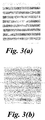
- a single layer carbon diffusion structure 15 formed from a commercially available woven cloth diffuser is compared with a three layer diffuser structure comprising the second, third and fourth layers discussed above in connection with figure 2 .
- Figure 3(a) shows a film impression from an extensometer after compression at 4000 N showing clear compaction of the single layer structure 15.
- Figure 3(b) shows a corresponding film impression of the three layer diffuser structure 24, 25, 26 using a structural layer 24 as defined above for the second layer.
- the spreading of compaction load also results in a more even intimate contact between the MEA 12 and the microdiffuser layer (fourth layer 26) resulting in improved current distribution and lower incidence of hot spots.
- hydrophilic first layer 23 in the diffusion structure 20 means that water droplets 18 are discouraged from forming. This is illustrated as mechanism 'A' in figure 2 . This is in comparison with the hydrophobic diffusion structure used in the prior art.
- the effect of the hydrophilic layer 23 adjacent to the fluid flow field plate 10 is to increase the 'evaporation area' for product water by the flow of air. This allows higher current operation and lower operating temperature with a much reduced risk of cathode flooding.
- the SGL30 third layer 25 has a lower pore volume than the SGL10 fourth layer 26 and is therefore more resistive to liquid water dispersal. Hence, water is encouraged to travel in a lateral (i.e. in-plane) direction through the fourth layer 26 and will begin to diffuse upwards through the third layer 25 only when there is a high water content in the fourth layer 26. This is illustrated in figure 2 as mechanism 'B'. The effect of this is to keep the MEA 12 better humidified. This has been confirmed by obtaining 'non-looped' polarisation curves where the potential values on the upwards current sweep closely match those on the downwards current sweep.
- figure 4 illustrates average cell potential and power density as a function of current density for various diffuser structures 15, 20.
- Curves 41 and 42 represent the power density as a function of current density, while curves 44 and 45 represent polarisation as a function of current density.
- Curve 41 represents a single layer diffusion structure 15 while curve 42 represents the multilayer structure 20 of figure 2 with hydrophilic layer 23 and structural layer 24.
- Curve 44 represents a single layer diffusion structure 15 while curve 45 represents the multilayer diffusion structure 20 of figure 2 with hydrophilic layer 23 and structural layer 24.
- the multi-layered diffusion structure 20 has an improved response to a large upwards shifts in load from open circuit. This is due to a 'water trap' effect of the multilayer arrangement where, during non-operational periods, there is a reduced natural removal of moisture from the membrane via the multilayer diffusion structure 20.
- a 'water trap' effect of the multilayer arrangement where, during non-operational periods, there is a reduced natural removal of moisture from the membrane via the multilayer diffusion structure 20.
- the multilayer diffuser structure 20 helps retain moisture in the MEA during non-use of the cells.
- This 'water-trap' tendency may also result in a greater degree of back diffusion from cathode to anode. This helps balance the water gradient across the membrane and thus thicker and more durable membrane structures can be used without a significant performance penalty. To the extent that that this adversely impacts the anode performance, it may be compensated for by providing a slightly higher PTFE content in the anode diffusion structure.
- the multilayer diffusion structure 20 may increase the bulk volume of each cell slightly, but this is compensated for by overall increases in the gravimetric and volumetric power stack densities.
- the beneficial effects of the multilayer diffusion structure 20 as described above are particularly evident in the cathode side of the fuel cell where water content control is generally a more significant factor.
- the principles are also applicable to the anode side of the fuel cell where humidification is also important and where compaction is also significant.
- the multilayer structure 20 may be used in one or both of the anode and cathode sides of the fuel cell.
- hydrophilic layer 23 and the structural layer 24 may be obtained alone or in combination with one another in a diffuser structure 20 although the best improvements are noted with the combined use of hydrophilic layer 23 and structural layer 24.
- hydrophilic layer 23 and the structural layer 24 may also be combined in a single layer by treating the structural layer 24 with a hydrophilic surface emulsion or similar structure treatment.
Landscapes
- Chemical & Material Sciences (AREA)
- Chemical Kinetics & Catalysis (AREA)
- Electrochemistry (AREA)
- General Chemical & Material Sciences (AREA)
- Life Sciences & Earth Sciences (AREA)
- Engineering & Computer Science (AREA)
- Manufacturing & Machinery (AREA)
- Sustainable Development (AREA)
- Sustainable Energy (AREA)
- Composite Materials (AREA)
- Fuel Cell (AREA)
- Inert Electrodes (AREA)
Applications Claiming Priority (2)
| Application Number | Priority Date | Filing Date | Title |
|---|---|---|---|
| GB0501598A GB2422716B (en) | 2005-01-26 | 2005-01-26 | Multi-layer fuel cell diffuser |
| PCT/GB2006/000074 WO2006079781A1 (en) | 2005-01-26 | 2006-01-11 | Multi-layer fuel cell diffuser |
Publications (2)
| Publication Number | Publication Date |
|---|---|
| EP1844509A1 EP1844509A1 (en) | 2007-10-17 |
| EP1844509B1 true EP1844509B1 (en) | 2016-03-23 |
Family
ID=34259694
Family Applications (1)
| Application Number | Title | Priority Date | Filing Date |
|---|---|---|---|
| EP06701351.6A Expired - Lifetime EP1844509B1 (en) | 2005-01-26 | 2006-01-11 | Multi-layer fuel cell diffuser |
Country Status (15)
| Country | Link |
|---|---|
| US (1) | US8043767B2 (enExample) |
| EP (1) | EP1844509B1 (enExample) |
| JP (1) | JP4521445B2 (enExample) |
| KR (1) | KR101297304B1 (enExample) |
| CN (1) | CN101107739B (enExample) |
| AR (1) | AR052364A1 (enExample) |
| BR (1) | BRPI0607072A2 (enExample) |
| CA (1) | CA2595342C (enExample) |
| GB (1) | GB2422716B (enExample) |
| MX (1) | MX2007008944A (enExample) |
| NO (1) | NO20073735L (enExample) |
| RU (1) | RU2384919C2 (enExample) |
| TW (1) | TWI382578B (enExample) |
| WO (1) | WO2006079781A1 (enExample) |
| ZA (1) | ZA200706167B (enExample) |
Families Citing this family (29)
| Publication number | Priority date | Publication date | Assignee | Title |
|---|---|---|---|---|
| GB2382455B (en) * | 2001-11-07 | 2004-10-13 | Intelligent Energy Ltd | Fuel cell fluid flow field plates |
| GB2412784B (en) * | 2002-01-18 | 2006-08-23 | Intelligent Energy Ltd | Fuel cell oxygen removal and pre-conditioning system |
| GB2390738B (en) * | 2002-07-09 | 2005-05-11 | Intelligent Energy Ltd | Fuel cell direct water injection |
| GB2401986B (en) | 2003-05-17 | 2005-11-09 | Intelligent Energy Ltd | Improvements in fuel utilisation in electrochemical fuel cells |
| GB2413002B (en) * | 2004-04-08 | 2006-12-06 | Intelligent Energy Ltd | Fuel cell gas distribution |
| GB2434845B (en) * | 2006-02-01 | 2010-10-13 | Intelligent Energy Ltd | Variable compressibility gaskets |
| JP4876766B2 (ja) | 2006-08-10 | 2012-02-15 | トヨタ自動車株式会社 | 燃料電池 |
| WO2008082407A1 (en) * | 2006-12-29 | 2008-07-10 | Utc Power Corporation | Hydrophilic layer for use in a fuel cell |
| DE102007014046B4 (de) * | 2007-03-23 | 2011-07-28 | Fraunhofer-Gesellschaft zur Förderung der angewandten Forschung e.V., 80686 | Brennstoffzelle sowie Verfahren zu deren Herstellung |
| JP2008243491A (ja) * | 2007-03-26 | 2008-10-09 | Toshiba Corp | 燃料電池 |
| WO2008151068A1 (en) * | 2007-05-31 | 2008-12-11 | Bdf Ip Holdings Ltd. | Method of making fluid diffusion layers for fuel cells |
| US20110114496A1 (en) * | 2008-07-15 | 2011-05-19 | Dopp Robert B | Electrochemical Devices, Systems, and Methods |
| US20100028744A1 (en) * | 2008-08-04 | 2010-02-04 | Gm Global Technology Operations, Inc. | Gas diffusion layer with lower gas diffusivity |
| US20100028750A1 (en) * | 2008-08-04 | 2010-02-04 | Gm Global Technology Operations, Inc. | Gas diffusion layer with lower gas diffusivity |
| US9281536B2 (en) * | 2008-10-01 | 2016-03-08 | GM Global Technology Operations LLC | Material design to enable high mid-temperature performance of a fuel cell with ultrathin electrodes |
| JP5337936B2 (ja) * | 2008-11-28 | 2013-11-06 | 日産自動車株式会社 | 固体高分子形燃料電池 |
| EP2675005A1 (en) * | 2012-06-11 | 2013-12-18 | HTceramix S.A. | Gas distribution element for a fuel cell |
| EP2675006A1 (en) | 2012-06-11 | 2013-12-18 | HTceramix S.A. | Gas distribution element with a supporting layer |
| KR101724972B1 (ko) * | 2015-12-15 | 2017-04-10 | 현대자동차주식회사 | 연료전지 셀 |
| KR102072861B1 (ko) * | 2016-06-07 | 2020-02-03 | 현대자동차주식회사 | 연료 전지용 전극막 접합체 |
| RU191123U1 (ru) * | 2018-04-09 | 2019-07-25 | Закрытое акционерное общество "Межрегиональное производственное объединение технического комплектования "ТЕХНОКОМПЛЕКТ" (ЗАО "МПОТК "ТЕХНОКОМПЛЕКТ") | Ячейка проточного аккумулятора |
| CN111029631B (zh) * | 2019-11-30 | 2022-10-25 | 华南理工大学 | 一种拱型自供氧余热利用式直接甲醇燃料电池 |
| US11724245B2 (en) | 2021-08-13 | 2023-08-15 | Amogy Inc. | Integrated heat exchanger reactors for renewable fuel delivery systems |
| US11994061B2 (en) | 2021-05-14 | 2024-05-28 | Amogy Inc. | Methods for reforming ammonia |
| JP2024521417A (ja) | 2021-06-11 | 2024-05-31 | アモジー インコーポレイテッド | アンモニアを処理するためのシステムおよび方法 |
| US11539063B1 (en) | 2021-08-17 | 2022-12-27 | Amogy Inc. | Systems and methods for processing hydrogen |
| US11834334B1 (en) | 2022-10-06 | 2023-12-05 | Amogy Inc. | Systems and methods of processing ammonia |
| US11866328B1 (en) | 2022-10-21 | 2024-01-09 | Amogy Inc. | Systems and methods for processing ammonia |
| US11795055B1 (en) | 2022-10-21 | 2023-10-24 | Amogy Inc. | Systems and methods for processing ammonia |
Family Cites Families (30)
| Publication number | Priority date | Publication date | Assignee | Title |
|---|---|---|---|---|
| ATE245852T1 (de) | 1995-10-06 | 2003-08-15 | Dow Global Technologies Inc | Fluessigkeitsverteilungsstrukturen fuer membran- elektrode-anordnungen von brennstoffzellen |
| US6183898B1 (en) * | 1995-11-28 | 2001-02-06 | Hoescht Research & Technology Deutschland Gmbh & Co. Kg | Gas diffusion electrode for polymer electrolyte membrane fuel cells |
| EP0791974B2 (en) * | 1996-02-28 | 2005-08-17 | Johnson Matthey Public Limited Company | Catalytically active gas diffusion electrodes comprising a nonwoven fibrous structure |
| US5952119A (en) * | 1997-02-24 | 1999-09-14 | Regents Of The University Of California | Fuel cell membrane humidification |
| DE19709199A1 (de) | 1997-03-06 | 1998-09-17 | Magnet Motor Gmbh | Gasdiffusionselektrode mit verringertem Diffusionsvermögen für Wasser und Verfahren zum Betreiben einer Polymerelektrolytmembran-Brennstoffzelle ohne Zuführung von Membranbefeuchtungswasser |
| AU1996099A (en) * | 1997-11-25 | 1999-06-15 | California Institute Of Technology | Fuel cell elements with improved water handling capacity |
| US6103077A (en) * | 1998-01-02 | 2000-08-15 | De Nora S.P.A. | Structures and methods of manufacture for gas diffusion electrodes and electrode components |
| DE19840517A1 (de) * | 1998-09-04 | 2000-03-16 | Manhattan Scientifics Inc | Gasdiffusionsstruktur senkrecht zur Membran von Polymerelektrolyt-Membran Brennstoffzellen |
| US6350539B1 (en) * | 1999-10-25 | 2002-02-26 | General Motors Corporation | Composite gas distribution structure for fuel cell |
| WO2002027846A2 (en) * | 2000-09-27 | 2002-04-04 | Proton Energy Systems, Inc. | Method and apparatus for improved fluid flow within an electrochemical cell |
| RU2198452C1 (ru) * | 2001-08-21 | 2003-02-10 | Государственное унитарное предприятие "Компания МЭТИС" | Способ сборки мембранно-электродного блока |
| DE10145875B4 (de) | 2001-09-18 | 2010-09-16 | Daimler Ag | Membran-Elektroden-Einheit für eine selbstbefeuchtende Brennstoffzelle |
| US6743543B2 (en) | 2001-10-31 | 2004-06-01 | Motorola, Inc. | Fuel cell using variable porosity gas diffusion material |
| GB2382455B (en) | 2001-11-07 | 2004-10-13 | Intelligent Energy Ltd | Fuel cell fluid flow field plates |
| GB2412784B (en) | 2002-01-18 | 2006-08-23 | Intelligent Energy Ltd | Fuel cell oxygen removal and pre-conditioning system |
| GB2387959C (en) | 2002-03-28 | 2005-02-09 | Intelligent Energy Ltd | Fuel cell compression assembly |
| JP4281382B2 (ja) * | 2002-04-19 | 2009-06-17 | ソニー株式会社 | 生成水処理システム及び発電装置 |
| JP2003331850A (ja) | 2002-05-10 | 2003-11-21 | Mitsubishi Electric Corp | 電極およびそれを用いた燃料電池 |
| JP3760895B2 (ja) * | 2002-07-03 | 2006-03-29 | 日本電気株式会社 | 液体燃料供給型燃料電池、燃料電池用電極、およびそれらの製造方法 |
| GB2396688B (en) | 2002-11-22 | 2006-06-28 | Intelligent Energy Ltd | Thermal energy management in electrochemical fuel cells |
| JP2004220843A (ja) * | 2003-01-10 | 2004-08-05 | Toyota Central Res & Dev Lab Inc | 膜電極接合体 |
| AU2003297702A1 (en) * | 2003-01-15 | 2004-08-13 | General Motors Corporation | Diffusion layer and fuel cells |
| US20040197629A1 (en) | 2003-01-20 | 2004-10-07 | Yasuo Arishima | Electric power generating element for fuel cell and fuel cell using the same |
| JP2004247294A (ja) * | 2003-01-20 | 2004-09-02 | Hitachi Maxell Ltd | 燃料電池用発電素子およびその製造方法ならびに前記発電素子を用いた燃料電池 |
| GB2401986B (en) | 2003-05-17 | 2005-11-09 | Intelligent Energy Ltd | Improvements in fuel utilisation in electrochemical fuel cells |
| GB2409763B (en) | 2003-12-31 | 2007-01-17 | Intelligent Energy Ltd | Water management in fuel cells |
| US20050185893A1 (en) * | 2004-02-20 | 2005-08-25 | Ansheng Liu | Method and apparatus for tapering an optical waveguide |
| GB2413002B (en) | 2004-04-08 | 2006-12-06 | Intelligent Energy Ltd | Fuel cell gas distribution |
| GB2422717B (en) | 2005-02-01 | 2007-11-14 | Intelligent Energy Ltd | Detachable fuel cell power unit for vehicle applications |
| GB2434845B (en) | 2006-02-01 | 2010-10-13 | Intelligent Energy Ltd | Variable compressibility gaskets |
-
2005
- 2005-01-26 GB GB0501598A patent/GB2422716B/en not_active Expired - Fee Related
-
2006
- 2006-01-11 WO PCT/GB2006/000074 patent/WO2006079781A1/en not_active Ceased
- 2006-01-11 CN CN2006800031639A patent/CN101107739B/zh not_active Expired - Fee Related
- 2006-01-11 EP EP06701351.6A patent/EP1844509B1/en not_active Expired - Lifetime
- 2006-01-11 BR BRPI0607072-8A patent/BRPI0607072A2/pt not_active Application Discontinuation
- 2006-01-11 MX MX2007008944A patent/MX2007008944A/es active IP Right Grant
- 2006-01-11 RU RU2007132073/09A patent/RU2384919C2/ru not_active IP Right Cessation
- 2006-01-11 JP JP2007551731A patent/JP4521445B2/ja not_active Expired - Lifetime
- 2006-01-11 CA CA2595342A patent/CA2595342C/en not_active Expired - Lifetime
- 2006-01-11 KR KR1020077019098A patent/KR101297304B1/ko not_active Expired - Lifetime
- 2006-01-11 US US11/814,492 patent/US8043767B2/en not_active Expired - Lifetime
- 2006-01-16 TW TW095101570A patent/TWI382578B/zh not_active IP Right Cessation
- 2006-01-26 AR ARP060100292A patent/AR052364A1/es not_active Application Discontinuation
-
2007
- 2007-07-18 NO NO20073735A patent/NO20073735L/no not_active Application Discontinuation
- 2007-07-25 ZA ZA200706107A patent/ZA200706167B/xx unknown
Also Published As
| Publication number | Publication date |
|---|---|
| RU2384919C2 (ru) | 2010-03-20 |
| RU2007132073A (ru) | 2009-03-10 |
| TWI382578B (zh) | 2013-01-11 |
| CA2595342C (en) | 2014-05-06 |
| KR20070107054A (ko) | 2007-11-06 |
| JP2008529211A (ja) | 2008-07-31 |
| GB2422716B (en) | 2007-08-22 |
| CN101107739A (zh) | 2008-01-16 |
| EP1844509A1 (en) | 2007-10-17 |
| CN101107739B (zh) | 2010-05-19 |
| CA2595342A1 (en) | 2006-08-03 |
| GB0501598D0 (en) | 2005-03-02 |
| TW200635105A (en) | 2006-10-01 |
| JP4521445B2 (ja) | 2010-08-11 |
| AR052364A1 (es) | 2007-03-14 |
| US20080145738A1 (en) | 2008-06-19 |
| GB2422716A (en) | 2006-08-02 |
| NO20073735L (no) | 2007-10-26 |
| WO2006079781A1 (en) | 2006-08-03 |
| US8043767B2 (en) | 2011-10-25 |
| KR101297304B1 (ko) | 2013-08-20 |
| ZA200706167B (en) | 2008-05-28 |
| BRPI0607072A2 (pt) | 2009-12-01 |
| MX2007008944A (es) | 2007-09-14 |
Similar Documents
| Publication | Publication Date | Title |
|---|---|---|
| EP1844509B1 (en) | Multi-layer fuel cell diffuser | |
| US7220513B2 (en) | Balanced humidification in fuel cell proton exchange membranes | |
| CA2490877C (en) | Humidity controlled solid polymer electrolyte fuel cell assembly | |
| JP4923319B2 (ja) | 燃料電池 | |
| US6756149B2 (en) | Electrochemical fuel cell with non-uniform fluid flow design | |
| US8034502B2 (en) | Water removal system for non-reactive regions in PEFMC stacks | |
| WO2004109833A2 (en) | Electrochemical fuel cell with fluid distribution layer having non-uniform permeability | |
| KR102084568B1 (ko) | 그래핀폼을 포함하는 가스유로/가스확산층 복합 기능 연료전지용 부재 | |
| JP5135370B2 (ja) | 固体高分子形燃料電池 | |
| WO2007083838A1 (ja) | 燃料電池 | |
| JP5124900B2 (ja) | スタック構造を有する燃料電池 | |
| JP5385371B2 (ja) | 燃料電池の分離プレート構成 | |
| JP4635462B2 (ja) | 多孔質のセパレータを備える燃料電池 | |
| JP4060736B2 (ja) | ガス拡散層およびこれを用いた燃料電池 | |
| JP2009048905A (ja) | 燃料電池 | |
| JP2005129431A (ja) | 燃料電池および燃料電池用ガスセパレータ | |
| JP2008146897A (ja) | 燃料電池用セパレータおよび燃料電池 |
Legal Events
| Date | Code | Title | Description |
|---|---|---|---|
| PUAI | Public reference made under article 153(3) epc to a published international application that has entered the european phase |
Free format text: ORIGINAL CODE: 0009012 |
|
| 17P | Request for examination filed |
Effective date: 20070824 |
|
| AK | Designated contracting states |
Kind code of ref document: A1 Designated state(s): AT BE BG CH CY CZ DE DK EE ES FI FR GB GR HU IE IS IT LI LT LU LV MC NL PL PT RO SE SI SK TR |
|
| DAX | Request for extension of the european patent (deleted) | ||
| 17Q | First examination report despatched |
Effective date: 20090323 |
|
| RAP1 | Party data changed (applicant data changed or rights of an application transferred) |
Owner name: INTELLIGENT ENERGY LIMITED |
|
| RAP1 | Party data changed (applicant data changed or rights of an application transferred) |
Owner name: INTELLIGENT ENERGY LIMITED |
|
| RAP1 | Party data changed (applicant data changed or rights of an application transferred) |
Owner name: INTELLIGENT ENERGY LIMITED |
|
| REG | Reference to a national code |
Ref country code: DE Ref legal event code: R079 Ref document number: 602006048331 Country of ref document: DE Free format text: PREVIOUS MAIN CLASS: H01M0004860000 Ipc: H01M0008100000 |
|
| RIC1 | Information provided on ipc code assigned before grant |
Ipc: H01M 4/86 20060101ALI20150622BHEP Ipc: H01M 8/02 20060101ALI20150622BHEP Ipc: H01M 8/10 20060101AFI20150622BHEP |
|
| GRAP | Despatch of communication of intention to grant a patent |
Free format text: ORIGINAL CODE: EPIDOSNIGR1 |
|
| GRAJ | Information related to disapproval of communication of intention to grant by the applicant or resumption of examination proceedings by the epo deleted |
Free format text: ORIGINAL CODE: EPIDOSDIGR1 |
|
| RIN1 | Information on inventor provided before grant (corrected) |
Inventor name: BENSON, PAUL ALAN |
|
| GRAP | Despatch of communication of intention to grant a patent |
Free format text: ORIGINAL CODE: EPIDOSNIGR1 |
|
| GRAJ | Information related to disapproval of communication of intention to grant by the applicant or resumption of examination proceedings by the epo deleted |
Free format text: ORIGINAL CODE: EPIDOSDIGR1 |
|
| INTG | Intention to grant announced |
Effective date: 20150803 |
|
| INTG | Intention to grant announced |
Effective date: 20150813 |
|
| GRAP | Despatch of communication of intention to grant a patent |
Free format text: ORIGINAL CODE: EPIDOSNIGR1 |
|
| GRAC | Information related to communication of intention to grant a patent modified |
Free format text: ORIGINAL CODE: EPIDOSCIGR1 |
|
| INTG | Intention to grant announced |
Effective date: 20150824 |
|
| INTC | Intention to grant announced (deleted) | ||
| INTG | Intention to grant announced |
Effective date: 20150915 |
|
| INTG | Intention to grant announced |
Effective date: 20150922 |
|
| GRAS | Grant fee paid |
Free format text: ORIGINAL CODE: EPIDOSNIGR3 |
|
| GRAA | (expected) grant |
Free format text: ORIGINAL CODE: 0009210 |
|
| RBV | Designated contracting states (corrected) |
Designated state(s): AT BE BG CH CY CZ DE DK EE ES FI FR GR HU IE IS IT LI LT LU LV MC NL PL PT RO SE SI SK TR |
|
| AK | Designated contracting states |
Kind code of ref document: B1 Designated state(s): AT BE BG CH CY CZ DE DK EE ES FI FR GR HU IE IS IT LI LT LU LV MC NL PL PT RO SE SI SK TR |
|
| REG | Reference to a national code |
Ref country code: CH Ref legal event code: EP |
|
| REG | Reference to a national code |
Ref country code: AT Ref legal event code: REF Ref document number: 783944 Country of ref document: AT Kind code of ref document: T Effective date: 20160415 |
|
| REG | Reference to a national code |
Ref country code: IE Ref legal event code: FG4D |
|
| REG | Reference to a national code |
Ref country code: DE Ref legal event code: R096 Ref document number: 602006048331 Country of ref document: DE |
|
| REG | Reference to a national code |
Ref country code: LT Ref legal event code: MG4D |
|
| REG | Reference to a national code |
Ref country code: NL Ref legal event code: MP Effective date: 20160323 |
|
| PG25 | Lapsed in a contracting state [announced via postgrant information from national office to epo] |
Ref country code: FI Free format text: LAPSE BECAUSE OF FAILURE TO SUBMIT A TRANSLATION OF THE DESCRIPTION OR TO PAY THE FEE WITHIN THE PRESCRIBED TIME-LIMIT Effective date: 20160323 Ref country code: GR Free format text: LAPSE BECAUSE OF FAILURE TO SUBMIT A TRANSLATION OF THE DESCRIPTION OR TO PAY THE FEE WITHIN THE PRESCRIBED TIME-LIMIT Effective date: 20160624 |
|
| REG | Reference to a national code |
Ref country code: AT Ref legal event code: MK05 Ref document number: 783944 Country of ref document: AT Kind code of ref document: T Effective date: 20160323 |
|
| PG25 | Lapsed in a contracting state [announced via postgrant information from national office to epo] |
Ref country code: LT Free format text: LAPSE BECAUSE OF FAILURE TO SUBMIT A TRANSLATION OF THE DESCRIPTION OR TO PAY THE FEE WITHIN THE PRESCRIBED TIME-LIMIT Effective date: 20160323 Ref country code: SE Free format text: LAPSE BECAUSE OF FAILURE TO SUBMIT A TRANSLATION OF THE DESCRIPTION OR TO PAY THE FEE WITHIN THE PRESCRIBED TIME-LIMIT Effective date: 20160323 Ref country code: LV Free format text: LAPSE BECAUSE OF FAILURE TO SUBMIT A TRANSLATION OF THE DESCRIPTION OR TO PAY THE FEE WITHIN THE PRESCRIBED TIME-LIMIT Effective date: 20160323 Ref country code: NL Free format text: LAPSE BECAUSE OF FAILURE TO SUBMIT A TRANSLATION OF THE DESCRIPTION OR TO PAY THE FEE WITHIN THE PRESCRIBED TIME-LIMIT Effective date: 20160323 |
|
| PG25 | Lapsed in a contracting state [announced via postgrant information from national office to epo] |
Ref country code: PL Free format text: LAPSE BECAUSE OF FAILURE TO SUBMIT A TRANSLATION OF THE DESCRIPTION OR TO PAY THE FEE WITHIN THE PRESCRIBED TIME-LIMIT Effective date: 20160323 Ref country code: EE Free format text: LAPSE BECAUSE OF FAILURE TO SUBMIT A TRANSLATION OF THE DESCRIPTION OR TO PAY THE FEE WITHIN THE PRESCRIBED TIME-LIMIT Effective date: 20160323 Ref country code: IS Free format text: LAPSE BECAUSE OF FAILURE TO SUBMIT A TRANSLATION OF THE DESCRIPTION OR TO PAY THE FEE WITHIN THE PRESCRIBED TIME-LIMIT Effective date: 20160723 |
|
| PG25 | Lapsed in a contracting state [announced via postgrant information from national office to epo] |
Ref country code: PT Free format text: LAPSE BECAUSE OF FAILURE TO SUBMIT A TRANSLATION OF THE DESCRIPTION OR TO PAY THE FEE WITHIN THE PRESCRIBED TIME-LIMIT Effective date: 20160725 Ref country code: CZ Free format text: LAPSE BECAUSE OF FAILURE TO SUBMIT A TRANSLATION OF THE DESCRIPTION OR TO PAY THE FEE WITHIN THE PRESCRIBED TIME-LIMIT Effective date: 20160323 Ref country code: SK Free format text: LAPSE BECAUSE OF FAILURE TO SUBMIT A TRANSLATION OF THE DESCRIPTION OR TO PAY THE FEE WITHIN THE PRESCRIBED TIME-LIMIT Effective date: 20160323 Ref country code: RO Free format text: LAPSE BECAUSE OF FAILURE TO SUBMIT A TRANSLATION OF THE DESCRIPTION OR TO PAY THE FEE WITHIN THE PRESCRIBED TIME-LIMIT Effective date: 20160323 Ref country code: ES Free format text: LAPSE BECAUSE OF FAILURE TO SUBMIT A TRANSLATION OF THE DESCRIPTION OR TO PAY THE FEE WITHIN THE PRESCRIBED TIME-LIMIT Effective date: 20160323 Ref country code: AT Free format text: LAPSE BECAUSE OF FAILURE TO SUBMIT A TRANSLATION OF THE DESCRIPTION OR TO PAY THE FEE WITHIN THE PRESCRIBED TIME-LIMIT Effective date: 20160323 |
|
| PG25 | Lapsed in a contracting state [announced via postgrant information from national office to epo] |
Ref country code: BE Free format text: LAPSE BECAUSE OF FAILURE TO SUBMIT A TRANSLATION OF THE DESCRIPTION OR TO PAY THE FEE WITHIN THE PRESCRIBED TIME-LIMIT Effective date: 20160323 Ref country code: IT Free format text: LAPSE BECAUSE OF FAILURE TO SUBMIT A TRANSLATION OF THE DESCRIPTION OR TO PAY THE FEE WITHIN THE PRESCRIBED TIME-LIMIT Effective date: 20160323 |
|
| REG | Reference to a national code |
Ref country code: DE Ref legal event code: R097 Ref document number: 602006048331 Country of ref document: DE |
|
| PLBE | No opposition filed within time limit |
Free format text: ORIGINAL CODE: 0009261 |
|
| STAA | Information on the status of an ep patent application or granted ep patent |
Free format text: STATUS: NO OPPOSITION FILED WITHIN TIME LIMIT |
|
| PG25 | Lapsed in a contracting state [announced via postgrant information from national office to epo] |
Ref country code: DK Free format text: LAPSE BECAUSE OF FAILURE TO SUBMIT A TRANSLATION OF THE DESCRIPTION OR TO PAY THE FEE WITHIN THE PRESCRIBED TIME-LIMIT Effective date: 20160323 |
|
| PG25 | Lapsed in a contracting state [announced via postgrant information from national office to epo] |
Ref country code: BG Free format text: LAPSE BECAUSE OF FAILURE TO SUBMIT A TRANSLATION OF THE DESCRIPTION OR TO PAY THE FEE WITHIN THE PRESCRIBED TIME-LIMIT Effective date: 20160623 |
|
| 26N | No opposition filed |
Effective date: 20170102 |
|
| PG25 | Lapsed in a contracting state [announced via postgrant information from national office to epo] |
Ref country code: SI Free format text: LAPSE BECAUSE OF FAILURE TO SUBMIT A TRANSLATION OF THE DESCRIPTION OR TO PAY THE FEE WITHIN THE PRESCRIBED TIME-LIMIT Effective date: 20160323 |
|
| REG | Reference to a national code |
Ref country code: DE Ref legal event code: R119 Ref document number: 602006048331 Country of ref document: DE |
|
| REG | Reference to a national code |
Ref country code: CH Ref legal event code: PL |
|
| PG25 | Lapsed in a contracting state [announced via postgrant information from national office to epo] |
Ref country code: MC Free format text: LAPSE BECAUSE OF FAILURE TO SUBMIT A TRANSLATION OF THE DESCRIPTION OR TO PAY THE FEE WITHIN THE PRESCRIBED TIME-LIMIT Effective date: 20160323 |
|
| REG | Reference to a national code |
Ref country code: FR Ref legal event code: ST Effective date: 20170929 |
|
| PG25 | Lapsed in a contracting state [announced via postgrant information from national office to epo] |
Ref country code: LI Free format text: LAPSE BECAUSE OF NON-PAYMENT OF DUE FEES Effective date: 20170131 Ref country code: CH Free format text: LAPSE BECAUSE OF NON-PAYMENT OF DUE FEES Effective date: 20170131 Ref country code: FR Free format text: LAPSE BECAUSE OF NON-PAYMENT OF DUE FEES Effective date: 20170131 |
|
| REG | Reference to a national code |
Ref country code: IE Ref legal event code: MM4A |
|
| PG25 | Lapsed in a contracting state [announced via postgrant information from national office to epo] |
Ref country code: LU Free format text: LAPSE BECAUSE OF NON-PAYMENT OF DUE FEES Effective date: 20170111 Ref country code: DE Free format text: LAPSE BECAUSE OF NON-PAYMENT OF DUE FEES Effective date: 20170801 |
|
| PG25 | Lapsed in a contracting state [announced via postgrant information from national office to epo] |
Ref country code: IE Free format text: LAPSE BECAUSE OF NON-PAYMENT OF DUE FEES Effective date: 20170111 |
|
| PG25 | Lapsed in a contracting state [announced via postgrant information from national office to epo] |
Ref country code: HU Free format text: LAPSE BECAUSE OF FAILURE TO SUBMIT A TRANSLATION OF THE DESCRIPTION OR TO PAY THE FEE WITHIN THE PRESCRIBED TIME-LIMIT; INVALID AB INITIO Effective date: 20060111 |
|
| PG25 | Lapsed in a contracting state [announced via postgrant information from national office to epo] |
Ref country code: CY Free format text: LAPSE BECAUSE OF NON-PAYMENT OF DUE FEES Effective date: 20160323 |
|
| PG25 | Lapsed in a contracting state [announced via postgrant information from national office to epo] |
Ref country code: TR Free format text: LAPSE BECAUSE OF FAILURE TO SUBMIT A TRANSLATION OF THE DESCRIPTION OR TO PAY THE FEE WITHIN THE PRESCRIBED TIME-LIMIT Effective date: 20160323 |