EP1843981B1 - Behandlungssystem mit einer dielektrischen sperrschichtlampe - Google Patents
Behandlungssystem mit einer dielektrischen sperrschichtlampe Download PDFInfo
- Publication number
- EP1843981B1 EP1843981B1 EP06710748A EP06710748A EP1843981B1 EP 1843981 B1 EP1843981 B1 EP 1843981B1 EP 06710748 A EP06710748 A EP 06710748A EP 06710748 A EP06710748 A EP 06710748A EP 1843981 B1 EP1843981 B1 EP 1843981B1
- Authority
- EP
- European Patent Office
- Prior art keywords
- lamp
- reactor
- treatment system
- medium
- electrode
- Prior art date
- Legal status (The legal status is an assumption and is not a legal conclusion. Google has not performed a legal analysis and makes no representation as to the accuracy of the status listed.)
- Not-in-force
Links
- 230000004888 barrier function Effects 0.000 title claims description 18
- 230000005855 radiation Effects 0.000 claims description 15
- 238000007788 roughening Methods 0.000 claims description 3
- 239000012530 fluid Substances 0.000 description 24
- XLYOFNOQVPJJNP-UHFFFAOYSA-N water Substances O XLYOFNOQVPJJNP-UHFFFAOYSA-N 0.000 description 16
- 238000010521 absorption reaction Methods 0.000 description 7
- 239000007789 gas Substances 0.000 description 4
- VYPSYNLAJGMNEJ-UHFFFAOYSA-N Silicium dioxide Chemical compound O=[Si]=O VYPSYNLAJGMNEJ-UHFFFAOYSA-N 0.000 description 3
- 230000003247 decreasing effect Effects 0.000 description 3
- 229910052751 metal Inorganic materials 0.000 description 3
- 239000002184 metal Substances 0.000 description 3
- 238000001816 cooling Methods 0.000 description 2
- 230000003287 optical effect Effects 0.000 description 2
- 239000011343 solid material Substances 0.000 description 2
- 239000000126 substance Substances 0.000 description 2
- CBENFWSGALASAD-UHFFFAOYSA-N Ozone Chemical compound [O-][O+]=O CBENFWSGALASAD-UHFFFAOYSA-N 0.000 description 1
- OAICVXFJPJFONN-UHFFFAOYSA-N Phosphorus Chemical compound [P] OAICVXFJPJFONN-UHFFFAOYSA-N 0.000 description 1
- 238000009303 advanced oxidation process reaction Methods 0.000 description 1
- 229910052782 aluminium Inorganic materials 0.000 description 1
- XAGFODPZIPBFFR-UHFFFAOYSA-N aluminium Chemical compound [Al] XAGFODPZIPBFFR-UHFFFAOYSA-N 0.000 description 1
- 239000003990 capacitor Substances 0.000 description 1
- 238000006243 chemical reaction Methods 0.000 description 1
- 238000005094 computer simulation Methods 0.000 description 1
- 239000004020 conductor Substances 0.000 description 1
- 230000008878 coupling Effects 0.000 description 1
- 238000010168 coupling process Methods 0.000 description 1
- 238000005859 coupling reaction Methods 0.000 description 1
- 239000003651 drinking water Substances 0.000 description 1
- 235000020188 drinking water Nutrition 0.000 description 1
- 230000000694 effects Effects 0.000 description 1
- 239000011521 glass Substances 0.000 description 1
- 230000000977 initiatory effect Effects 0.000 description 1
- 230000031700 light absorption Effects 0.000 description 1
- 238000004519 manufacturing process Methods 0.000 description 1
- 239000000463 material Substances 0.000 description 1
- QSHDDOUJBYECFT-UHFFFAOYSA-N mercury Chemical compound [Hg] QSHDDOUJBYECFT-UHFFFAOYSA-N 0.000 description 1
- 229910052753 mercury Inorganic materials 0.000 description 1
- 238000000034 method Methods 0.000 description 1
- 238000001228 spectrum Methods 0.000 description 1
- 235000013599 spices Nutrition 0.000 description 1
- 238000004659 sterilization and disinfection Methods 0.000 description 1
- 239000008399 tap water Substances 0.000 description 1
- 235000020679 tap water Nutrition 0.000 description 1
- 229910021642 ultra pure water Inorganic materials 0.000 description 1
- 239000012498 ultrapure water Substances 0.000 description 1
Images

Classifications
-
- C—CHEMISTRY; METALLURGY
- C02—TREATMENT OF WATER, WASTE WATER, SEWAGE, OR SLUDGE
- C02F—TREATMENT OF WATER, WASTE WATER, SEWAGE, OR SLUDGE
- C02F1/00—Treatment of water, waste water, or sewage
- C02F1/30—Treatment of water, waste water, or sewage by irradiation
- C02F1/32—Treatment of water, waste water, or sewage by irradiation with ultraviolet light
- C02F1/325—Irradiation devices or lamp constructions
-
- A—HUMAN NECESSITIES
- A61—MEDICAL OR VETERINARY SCIENCE; HYGIENE
- A61L—METHODS OR APPARATUS FOR STERILISING MATERIALS OR OBJECTS IN GENERAL; DISINFECTION, STERILISATION OR DEODORISATION OF AIR; CHEMICAL ASPECTS OF BANDAGES, DRESSINGS, ABSORBENT PADS OR SURGICAL ARTICLES; MATERIALS FOR BANDAGES, DRESSINGS, ABSORBENT PADS OR SURGICAL ARTICLES
- A61L2/00—Methods or apparatus for disinfecting or sterilising materials or objects other than foodstuffs or contact lenses; Accessories therefor
- A61L2/02—Methods or apparatus for disinfecting or sterilising materials or objects other than foodstuffs or contact lenses; Accessories therefor using physical phenomena
- A61L2/08—Radiation
- A61L2/084—Visible light
-
- A—HUMAN NECESSITIES
- A61—MEDICAL OR VETERINARY SCIENCE; HYGIENE
- A61L—METHODS OR APPARATUS FOR STERILISING MATERIALS OR OBJECTS IN GENERAL; DISINFECTION, STERILISATION OR DEODORISATION OF AIR; CHEMICAL ASPECTS OF BANDAGES, DRESSINGS, ABSORBENT PADS OR SURGICAL ARTICLES; MATERIALS FOR BANDAGES, DRESSINGS, ABSORBENT PADS OR SURGICAL ARTICLES
- A61L2/00—Methods or apparatus for disinfecting or sterilising materials or objects other than foodstuffs or contact lenses; Accessories therefor
- A61L2/02—Methods or apparatus for disinfecting or sterilising materials or objects other than foodstuffs or contact lenses; Accessories therefor using physical phenomena
- A61L2/08—Radiation
- A61L2/10—Ultra-violet radiation
-
- A—HUMAN NECESSITIES
- A61—MEDICAL OR VETERINARY SCIENCE; HYGIENE
- A61L—METHODS OR APPARATUS FOR STERILISING MATERIALS OR OBJECTS IN GENERAL; DISINFECTION, STERILISATION OR DEODORISATION OF AIR; CHEMICAL ASPECTS OF BANDAGES, DRESSINGS, ABSORBENT PADS OR SURGICAL ARTICLES; MATERIALS FOR BANDAGES, DRESSINGS, ABSORBENT PADS OR SURGICAL ARTICLES
- A61L9/00—Disinfection, sterilisation or deodorisation of air
- A61L9/16—Disinfection, sterilisation or deodorisation of air using physical phenomena
- A61L9/18—Radiation
- A61L9/20—Ultra-violet radiation
-
- B—PERFORMING OPERATIONS; TRANSPORTING
- B01—PHYSICAL OR CHEMICAL PROCESSES OR APPARATUS IN GENERAL
- B01J—CHEMICAL OR PHYSICAL PROCESSES, e.g. CATALYSIS OR COLLOID CHEMISTRY; THEIR RELEVANT APPARATUS
- B01J19/00—Chemical, physical or physico-chemical processes in general; Their relevant apparatus
- B01J19/08—Processes employing the direct application of electric or wave energy, or particle radiation; Apparatus therefor
- B01J19/12—Processes employing the direct application of electric or wave energy, or particle radiation; Apparatus therefor employing electromagnetic waves
- B01J19/122—Incoherent waves
- B01J19/123—Ultra-violet light
-
- C—CHEMISTRY; METALLURGY
- C01—INORGANIC CHEMISTRY
- C01B—NON-METALLIC ELEMENTS; COMPOUNDS THEREOF; METALLOIDS OR COMPOUNDS THEREOF NOT COVERED BY SUBCLASS C01C
- C01B13/00—Oxygen; Ozone; Oxides or hydroxides in general
- C01B13/10—Preparation of ozone
- C01B13/11—Preparation of ozone by electric discharge
-
- H—ELECTRICITY
- H01—ELECTRIC ELEMENTS
- H01J—ELECTRIC DISCHARGE TUBES OR DISCHARGE LAMPS
- H01J61/00—Gas-discharge or vapour-discharge lamps
- H01J61/02—Details
- H01J61/04—Electrodes; Screens; Shields
- H01J61/06—Main electrodes
-
- H—ELECTRICITY
- H01—ELECTRIC ELEMENTS
- H01J—ELECTRIC DISCHARGE TUBES OR DISCHARGE LAMPS
- H01J65/00—Lamps without any electrode inside the vessel; Lamps with at least one main electrode outside the vessel
- H01J65/04—Lamps in which a gas filling is excited to luminesce by an external electromagnetic field or by external corpuscular radiation, e.g. for indicating plasma display panels
- H01J65/042—Lamps in which a gas filling is excited to luminesce by an external electromagnetic field or by external corpuscular radiation, e.g. for indicating plasma display panels by an external electromagnetic field
-
- B—PERFORMING OPERATIONS; TRANSPORTING
- B01—PHYSICAL OR CHEMICAL PROCESSES OR APPARATUS IN GENERAL
- B01J—CHEMICAL OR PHYSICAL PROCESSES, e.g. CATALYSIS OR COLLOID CHEMISTRY; THEIR RELEVANT APPARATUS
- B01J2219/00—Chemical, physical or physico-chemical processes in general; Their relevant apparatus
- B01J2219/08—Processes employing the direct application of electric or wave energy, or particle radiation; Apparatus therefor
- B01J2219/0803—Processes employing the direct application of electric or wave energy, or particle radiation; Apparatus therefor employing electric or magnetic energy
- B01J2219/0805—Processes employing the direct application of electric or wave energy, or particle radiation; Apparatus therefor employing electric or magnetic energy giving rise to electric discharges
- B01J2219/0807—Processes employing the direct application of electric or wave energy, or particle radiation; Apparatus therefor employing electric or magnetic energy giving rise to electric discharges involving electrodes
- B01J2219/0809—Processes employing the direct application of electric or wave energy, or particle radiation; Apparatus therefor employing electric or magnetic energy giving rise to electric discharges involving electrodes employing two or more electrodes
- B01J2219/0811—Processes employing the direct application of electric or wave energy, or particle radiation; Apparatus therefor employing electric or magnetic energy giving rise to electric discharges involving electrodes employing two or more electrodes employing three electrodes
-
- B—PERFORMING OPERATIONS; TRANSPORTING
- B01—PHYSICAL OR CHEMICAL PROCESSES OR APPARATUS IN GENERAL
- B01J—CHEMICAL OR PHYSICAL PROCESSES, e.g. CATALYSIS OR COLLOID CHEMISTRY; THEIR RELEVANT APPARATUS
- B01J2219/00—Chemical, physical or physico-chemical processes in general; Their relevant apparatus
- B01J2219/08—Processes employing the direct application of electric or wave energy, or particle radiation; Apparatus therefor
- B01J2219/0803—Processes employing the direct application of electric or wave energy, or particle radiation; Apparatus therefor employing electric or magnetic energy
- B01J2219/0805—Processes employing the direct application of electric or wave energy, or particle radiation; Apparatus therefor employing electric or magnetic energy giving rise to electric discharges
- B01J2219/0807—Processes employing the direct application of electric or wave energy, or particle radiation; Apparatus therefor employing electric or magnetic energy giving rise to electric discharges involving electrodes
- B01J2219/0824—Details relating to the shape of the electrodes
- B01J2219/0826—Details relating to the shape of the electrodes essentially linear
- B01J2219/0828—Wires
-
- B—PERFORMING OPERATIONS; TRANSPORTING
- B01—PHYSICAL OR CHEMICAL PROCESSES OR APPARATUS IN GENERAL
- B01J—CHEMICAL OR PHYSICAL PROCESSES, e.g. CATALYSIS OR COLLOID CHEMISTRY; THEIR RELEVANT APPARATUS
- B01J2219/00—Chemical, physical or physico-chemical processes in general; Their relevant apparatus
- B01J2219/08—Processes employing the direct application of electric or wave energy, or particle radiation; Apparatus therefor
- B01J2219/0803—Processes employing the direct application of electric or wave energy, or particle radiation; Apparatus therefor employing electric or magnetic energy
- B01J2219/0805—Processes employing the direct application of electric or wave energy, or particle radiation; Apparatus therefor employing electric or magnetic energy giving rise to electric discharges
- B01J2219/0807—Processes employing the direct application of electric or wave energy, or particle radiation; Apparatus therefor employing electric or magnetic energy giving rise to electric discharges involving electrodes
- B01J2219/0824—Details relating to the shape of the electrodes
- B01J2219/0826—Details relating to the shape of the electrodes essentially linear
- B01J2219/083—Details relating to the shape of the electrodes essentially linear cylindrical
-
- B—PERFORMING OPERATIONS; TRANSPORTING
- B01—PHYSICAL OR CHEMICAL PROCESSES OR APPARATUS IN GENERAL
- B01J—CHEMICAL OR PHYSICAL PROCESSES, e.g. CATALYSIS OR COLLOID CHEMISTRY; THEIR RELEVANT APPARATUS
- B01J2219/00—Chemical, physical or physico-chemical processes in general; Their relevant apparatus
- B01J2219/08—Processes employing the direct application of electric or wave energy, or particle radiation; Apparatus therefor
- B01J2219/0873—Materials to be treated
- B01J2219/0877—Liquid
-
- C—CHEMISTRY; METALLURGY
- C01—INORGANIC CHEMISTRY
- C01B—NON-METALLIC ELEMENTS; COMPOUNDS THEREOF; METALLOIDS OR COMPOUNDS THEREOF NOT COVERED BY SUBCLASS C01C
- C01B2201/00—Preparation of ozone by electrical discharge
- C01B2201/10—Dischargers used for production of ozone
- C01B2201/14—Concentric/tubular dischargers
-
- C—CHEMISTRY; METALLURGY
- C02—TREATMENT OF WATER, WASTE WATER, SEWAGE, OR SLUDGE
- C02F—TREATMENT OF WATER, WASTE WATER, SEWAGE, OR SLUDGE
- C02F2201/00—Apparatus for treatment of water, waste water or sewage
- C02F2201/32—Details relating to UV-irradiation devices
- C02F2201/322—Lamp arrangement
- C02F2201/3223—Single elongated lamp located on the central axis of a turbular reactor
-
- C—CHEMISTRY; METALLURGY
- C02—TREATMENT OF WATER, WASTE WATER, SEWAGE, OR SLUDGE
- C02F—TREATMENT OF WATER, WASTE WATER, SEWAGE, OR SLUDGE
- C02F2201/00—Apparatus for treatment of water, waste water or sewage
- C02F2201/32—Details relating to UV-irradiation devices
- C02F2201/322—Lamp arrangement
- C02F2201/3228—Units having reflectors, e.g. coatings, baffles, plates, mirrors
Definitions
- the invention relates to a treatment system or a treatment reactor comprising a housing with at least one dielectric barrier discharge lamp and a medium like a fluid and/or a gas and/or a solid material which is to be treated by means of the radiation generated by the lamp.
- dielectric barrier discharge lamps are of increasing importance especially as a source for generating high intensive and high power UV light within a narrow spectrum and with a high efficiency.
- these lamps have a cylindrical, a dome shaped or a coaxial design and they are cooled by means of an internal and/or an external flow of water.
- the basic principle of these lamps is the generation of excimer radiation by means of a dielectric barrier discharge.
- at least one of the two electrodes of such a lamp is located outside the discharge volume at or around the lamp envelope so that the energy supply is accomplished by capacitive coupling through the walls of the lamp envelope into the discharge volume to initiate within this volume the gas discharge.
- the energy supply of the lamp can be fed via the treated fluid (see US 6633109 and US 5843784 ), and the outer electrode which is in electrical contact with the fluid does not need to be positioned directly at the lamp envelope.
- the housing of a related fluid treatment system or reactor which contains the dielectric barrier discharge lamp and the fluid is electrically conductive as well, the energy supply of the lamp can be fed via the housing and the fluid.
- the fluid layer between the lamp envelope and the housing of the treatment system or reactor can electrically be described as a parallel connection of a resistor and a capacitor wherein the resistance and the capacitance of these elements are given by the conductivity of the fluid, the permittivity of the fluid and the thickness of the fluid layer.
- One object underlying the invention is to provide a treatment system or reactor comprising at least one dielectric barrier discharge lamp by which these disadvantages are at least substantially avoided.
- a treatment system or reactor comprising at least one dielectric barrier discharge lamp by which a medium with a low conductivity, especially a fluid, can be treated by irradiation with high efficiency.
- Another object underlying the invention is to provide a treatment system or reactor comprising at least one dielectric barrier discharge lamp, in which influences of the treated medium on the electrical behavior of the treatment system or reactor and especially of the at least one lamp are at least substantially avoided.
- a treatment system or reactor comprising a housing with at least one dielectric barrier discharge lamp with a first electrode, a sleeve surrounding the lamp, wherein a volume comprising the medium to be treated by the radiation of the lamp extends between the sleeve and the housing, and wherein at least one second electrode of at least one lamp is provided by an electrically conductive medium in a space that extends between the at least one lamp and the sleeve and at least one electrically conductive body which is in electrical contact with the medium, wherein the medium within the space is highly transparent for the radiation generated by the lamp and has an electrical conductivity which is higher than the electrical conductivity of the medium within the volume.
- An advantage of this solution is the fact that even such a medium, especially a fluid, can be treated in an efficient and/or economic way which has a conductivity which varies during the treatment while simultaneously providing an intensive cooling of the discharge lamp.
- DE4022279A1 discloses a treatment system comprising an electrically conductive housing with at least one dielectric barrier discharge lamp having a first electrode, a second electrode provided in the medium to be treated by the system and in an intermediate position between the lamp and the housing, and a third electrode provided by the housing itself.
- a system with conductive means to provide energy to the dielectric barrier discharge lamp that can simultaneously be used for cooling of the lamp.
- the housing is electrically conductive, it can be used as an additional second (or a third) electrode of the lamp in order to improve the electrical behavior of the lamp and to minimize influences of the medium to be treated on the electrical behavior.
- Claims 3 and 4 are directed on preferred potentials of the outer (second and/or third) electrode which are selected especially in dependence on the electrical conductivity of the medium.
- Claims 5 and 6 are directed on preferred electrically conductive bodies, which have the advantage that they have a reduced absorption of light radiated by the lamp, by having a highly reflective surface (claim 5) or a transparent body (claim 6).
- an increased contact area between the conductive body (electrode) and the surrounding medium is obtained which is advantageous especially for a medium with a low electrical conductivity.
- Claim 8 discloses a reactor design which can be selected in order to obtain a more turbulent flow of the medium to be treated.
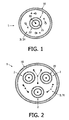
- Figure 1 shows a cross section through a first embodiment of a system or reactor 1 according to the prior art for treating a medium 3, especially a fluid (e.g. water) by irradiation in order for example to disinfect, to clean or to activate the medium or for other purposes.
- a medium 3 especially a fluid (e.g. water) by irradiation in order for example to disinfect, to clean or to activate the medium or for other purposes.
- a fluid e.g. water
- the system or reactor 1 comprises a substantially cylindrical housing 10, which is preferably electrically conductive and made of metal.
- the housing 10 can be made partly or totally of non electrically conductive materials as well like e.g. glass.
- the housing 10 encloses a coaxial dielectric barrier discharge lamp 2 which in this embodiment extends substantially along the axis of the cylindrical housing 10.
- the lamp 2 comprises a coaxial arrangement of an inner tube 21 and an outer tube 22 which are connected together at their axial ends so that a ring-shaped space (lamp envelope) is delimited between both in which a discharge gas is enclosed.
- a first (inner) electrode 20 (usually a high voltage electrode in the form of a rod) is positioned which is preferably cooled with water flowing within the inner tube 21 and which is not in direct contact with the treated medium.
- the medium 3 to be treated by irradiation of light generated by the lamp 2 (especially UV light) is guided in the axial direction or a radial direction (cross flow) or any other direction of the lamp 2 or the housing 10.
- the lamp 2 can be a phosphor coated lamp as disclosed in EP 1048620B1 or any other coaxial dielectric barrier discharge lamp.
- a lamp is used which has no outer (second) electrode (which is usually realized in the form of a grid enclosing the lamp envelope) but has only an inner (first) electrode 20 which is either positioned within the discharge volume of the lamp 2 or - as shown in Figures 1 to 3 - outside the lamp envelope but within the inner tube 21 of the lamp.
- second electrode which is usually realized in the form of a grid enclosing the lamp envelope
- first electrode 20 which is either positioned within the discharge volume of the lamp 2 or - as shown in Figures 1 to 3 - outside the lamp envelope but within the inner tube 21 of the lamp.
- At least one outer (second) electrode of the lamp 2 is provided by the (electrically conductive) medium 3 which surrounds the outer tube 22 of the lamp 2 and at least one electrically conductive body 4 which is in electrical contact with the medium 3 and arranged in an intermediate position between the housing 10 and the outer tube 22 of the lamp 2, i.e. within the volume 31.
- the housing 10 of the treatment reactor 1 is electrically conductive, the housing 10 can be used as another outer second or a third electrode, which is preferably connected to a ground potential and thus constitutes a part of the current-carrying circuit of the lamp 2.
- all intermediate electrodes 4 can be used either as the only outer (second) electrode of the lamp, or additionally, e.g. the housing 10 is provided as an outer second or another third electrode as well.
- the intermediate electrodes 4; 5, 6, 7 and the housing 10 are preferably connected to the same potential.
- the potential can be either a ground potential so that the intermediate electrodes preferably serve as a counter electrode for the (first) electrode 20 within the lamp 2 (which is usually a high voltage electrode), or any other potential (not shown in the Figures).
- the housing 10 is provided as a third electrode, it can have another potential than the intermediate electrodes 4; 5, 6, 7.
- the intermediate electrodes can comprise one or a plurality of electrically conductive bodies, rods and/or wires 4 which are inserted into the medium 3 (and the volume 31 accordingly).
- the following embodiments are exemplarily related to intermediate electrodes in the form of counter electrodes.
- the influences of the resistance and the capacity of the medium 3 within the volume 31 on the electrical behavior of the treatment system or reactor 1 and especially on the operating conditions of the lamp 2, can be reduced to a minimum. Accordingly, the power losses within the medium 3 can be decreased as well.
- the following table exemplarily gives an estimation for a maximum allowable thickness of a water layer (medium 3) between the lamp 2 and the conductive bodies 4 in dependence on the water conductivity and the relative water losses.
- This estimation is based on a computer simulation (SPICE), in which the lamp 2 and the water layer are represented by discrete - partially non-linear - electrical components and in which a realistic voltage signal is applied.
- SPICE computer simulation
- the numerical values for the maximum allowable thickness of the water layer in the above table give an indication in which distance from the outer tube 22 of the lamp 2 the conductive bodies 4 have to be positioned in order to reduce the water losses to the given values, even if the distance between the outer tube 22 of the lamp 2 and the reactor housing 10 is much larger.
- the location and/or the shape and/or design and/or the surface and/or the number of the at least one conductive body 4 is preferably chosen in such a way that the absorption and/or shadowing of the lamp light caused by the bodies 4 is minimal and will not have a significant influence on the efficiency of the treatment system or reactor 1.
- the conductive bodies 4 are for example realized according to at least one of the following alternatives:
- the surface of the bodies 4 can be made highly reflective for the emission wavelength of the lamp 2.
- e.g. aluminum rods can be used which are polished by mechanical and/or chemical and/or electromechanical means to enhance the reflectance at the emission wavelength of the lamp 2.
- the bodies 4 can be made at least partially transparent for the light radiated by the lamp 2.
- rods comprising through-holes along the axis of the rods, which are oriented in a radial direction of the lamp to let the lamp radiation pass through in order to minimize the optical absorption of the metal rod can be used.
- bodies 4 which are made of quartz glass tubes and which are filled with a conductive and radiation-transparent fluid like for example tap water.
- the electrical contacting of the bodies 4 can be realized by means of a thin metal wire which is inserted into the quartz glass tube and which is connected to the related potential.
- bodies 4 in the form of rods with an enlarged surface area which is achieved e.g. by surface roughening methods, in particular by mechanical and/or chemical and/or electrochemical surface roughening.
- the bodies are provided in the form of rods 4 which extend substantially parallel to the axis of the lamp 2 and which are equally distributed along the circumference of the lamp 2.
- the diameter of the rods 4 according to Figure 1 is dimensioned such that it is significantly smaller than the thickness of the medium layer, i.e. the distance between the outer tube 22 of the lamp 2 and the housing 10 of the treatment reactor 1, in order to minimize the optical absorption by the rods 4.
- the ratio between the diameter of a rod 4 and the diameter of the lamp 2 is advantageously chosen between about 1:10 and about 1:100.
- the ratio between the diameter of the rod 4 on the one hand and the distance between the outer tube 22 of the lamp 2 and the housing 10 on the other hand is advantageously chosen between about 1:10 and about 1:100.
- rods 4 do not need to be straight but can alternatively be bent to avoid complete shadowing of parts of the medium stream. Furthermore, another number and positioning of the rods 4 can be used in order to further decrease the power losses and by this to increase the efficiency of the treatment of the medium 3.
- a body 4 in the form of a grid or a helix made from wires can be used as well within the volume 31 between the outer tube 22 of the lamp 2 and the housing 10 of the treatment reactor 1.
- FIG. 1 exemplarily shows a second embodiment of such a treatment system or reactor 1 with a cylindrical housing 10.
- the housing 10 encloses three dielectric barrier discharge lamps 2 which are positioned at least substantially parallel to the axis of the housing 10.
- a medium 3 (especially a fluid) to be treated by the light generated by the lamps 2 is guided in the axial direction, a radial direction (cross flow) and/or any other direction of the lamps 2 or housing 10. Furthermore, in this volume 31 at least one body in the form of a metallic rod 4 is positioned as mentioned above with respect to the first embodiment.
- the location and/or the shape and/or design and/or the surface and/or number of these rods 4 is again chosen so that the power loss in the treated medium 3 is minimal and the efficiency of the treatment system or reactor 1 as explained above is improved.
- An advantage of this second embodiment is the fact that at least one of the rods 4 can serve for more than one lamp 2. Due to this the number of rods 4 for each lamp 2 and consequently the absorption and/or shadowing of light at these rods 4 can be decreased considerably.
- an intermediate counter electrode 5, 6, 7 (second electrode) as shown in Figure 3 is provided.
- This system again comprises a treatment reactor 1 with a cylindrical housing 10.
- the housing 10 encloses at least one dielectric barrier discharge lamp 2 which extends along the axis of the housing 10 according to Figure 1 .
- the intermediate counter electrode comprises a sleeve 5 which coaxially surrounds the lamp 2.
- the sleeve 5 is made from a material which is transparent for the radiation generated by the lamp 2, e.g. quartz glass.
- the space 61 between the sleeve 5 and the outer tube 22 of the lamp 2 is filled with an electrically conductive and radiation transparent medium 6 (which constitutes an intermediate electrode) like e.g. water.
- an electrically conductive and radiation transparent medium 6 which constitutes an intermediate electrode
- one or a plurality of electrically conductive bodies in the form of thin wires or rods 7 is positioned within this space 61 (and in electrical contact with the medium 6) which extend substantially parallel to the axis of the cylindrical housing 10 or which are arranged in another way as described above with respect to the rods 4.
- the medium 3 which is to be treated by the light radiated by the lamp 2 is guided in a volume 31 between the sleeve 5 and the reactor housing 10 in the axial direction or a radial direction (cross flow) or any other direction of the lamp 2 or the housing 10.
- the wires or rods 7 are provided for electrically contacting the intermediate electrode (i.e. the medium 6) and are preferably connected to a ground potential.
- the conductivity of the medium 6 within the space 61 is made (significantly) higher than the conductivity of the medium 3.
- This embodiment can be combined with intermediate (counter) electrodes according to the first and second embodiments ( Figures 1 and 2 ) as well.
- the number and positions of the intermediate counter electrodes within the reactor 1 is selected such that the electrical power loss within the medium 3 to be treated and the loss of light generated by the lamp(s) 2 is decreased and by this the treatment efficiency of the reactor 1 is increased. Consequently, a large number of electrodes 4; 7 in the near surroundings of the lamp 2 has the advantage of a minimum loss of electrical power, but the disadvantage of a maximum loss of light, and vice versa. Consequently, for a maximum efficiency of the whole system, a compromise has to be made between both.
- the invention can advantageously be used for the treatment especially of fluids even if the conductivity of the fluid is in such a range or varies to such an extent that by a reactor design according to the prior art no efficient and/or economical operation could be achieved.
- the treatment system according to the invention can especially be provided in the form of a drinking water treatment and/or disinfection system or a system for the production of ultra pure water using dielectric barrier discharge lamps.
- lamps 2 with a UV radiation in the range between about 200 nm and about 280 nm are used.
- the treatment system according to the invention can as well be provided for the treatment of gases or solid materials or their surfaces, for the generation of ozone or for initiating of advanced oxidation processes of the medium and/or to cure the medium and/or to stimulate any other chemical reaction.
Claims (8)
- Behandlungssystem oder -reaktor (1), das/der ein Gehäuse (10) mit mindestens einer dielektrischen Barrieren-Entladungslampe (2) mit einer ersten Elektrode (20), einem die Lampe (2) umgebenden Mantel (5), wobei ein Volumen (31) mit einem durch die Strahlung der Lampe (2) zu behandelnden Medium (3) sich zwischen dem Mantel (5) und dem Gehäuse (10) erstreckt, und wobei mindestens eine zweite Elektrode der mindestens einen Lampe (2) durch ein elektrisch leitendes Medium (6) in einem Raum (61), der sich zwischen der mindestens einen Lampe (2) und dem Mantel (5) erstreckt, vorgesehen ist, sowie mindestens einen elektrisch leitenden Körper (7), der in elektrischem Kontakt mit dem elektrisch leitenden Medium (6) ist, umfasst, wobei das elektrisch leitende Medium (6) innerhalb des Raumes (61) für die von der Lampe (2) erzeugte Strahlung stark durchlässig ist und eine elektrische Leitfähigkeit aufweist, die höher als die elektrische Leitfähigkeit des innerhalb des Volumens (31) zu behandelnden Mediums (3) ist.
- Behandlungssystem oder -reaktor (1) nach Anspruch 1,
wobei das Gehäuse (10) elektrisch leitend ist und eine dritte Elektrode von mindestens einer Lampe (2) bildet. - Behandlungssystem oder -reaktor (1) nach Anspruch 2,
wobei die mindestens eine zweite (5, 7) und die dritte Elektrode (10) zumindest im Wesentlichen das gleiche elektrische Potential aufweisen. - Behandlungssystem oder -reaktor (1) nach Anspruch 1,
wobei mindestens eine zweite Elektrode (5, 7) mit einem Erdpotential verbunden und als eine zwischenliegende Gegenelektrode in Beziehung zu der ersten Elektrode (20) vorgesehen ist. - Behandlungssystem oder -reaktor (1) nach Anspruch 1,
wobei mindestens ein elektrisch leitender Körper (7) in Form eines Stabs oder Drahts realisiert wird, der sich zumindest im Wesentlichen parallel zu der mindestens einen Lampe (2) erstreckt und der mit einer Oberfläche versehen ist, die für die von der Lampe (2) erzeugte Strahlung hoch reflektiv ist. - Behandlungssystem oder -reaktor (1) nach Anspruch 1,
wobei mindestens ein elektrisch leitender Körper (7) in Form eines Metallstabs mit Durchgangslöchern, die in einer radialen Richtung der Lampe (2) orientiert sind, vorgesehen ist. - Behandlungssystem oder -reaktor (1) nach Anspruch 1,
wobei mindestens ein elektrisch leitender Körper (7) in Form eines Metallstabs mit einem Oberflächenbereich, der durch Aufrauen der Oberfläche vergrößert wird, vorgesehen ist. - Behandlungssystem oder -reaktor (1) nach Anspruch 1,
wobei die mindestens eine dielektrische Barrieren-Entladungslampe (2) so innerhalb des Gehäuses (10) positioniert ist, dass das zu behandelnde Medium (3) in einer Querstromrichtung relativ zu der Achse der Lampe (2) zugeführt wird.
Priority Applications (1)
| Application Number | Priority Date | Filing Date | Title |
|---|---|---|---|
| EP06710748A EP1843981B1 (de) | 2005-01-28 | 2006-01-25 | Behandlungssystem mit einer dielektrischen sperrschichtlampe |
Applications Claiming Priority (3)
| Application Number | Priority Date | Filing Date | Title |
|---|---|---|---|
| EP05100564 | 2005-01-28 | ||
| EP06710748A EP1843981B1 (de) | 2005-01-28 | 2006-01-25 | Behandlungssystem mit einer dielektrischen sperrschichtlampe |
| PCT/IB2006/050272 WO2006079982A1 (en) | 2005-01-28 | 2006-01-25 | Treatment system comprising a dielectric barrier discharge lamp |
Publications (2)
| Publication Number | Publication Date |
|---|---|
| EP1843981A1 EP1843981A1 (de) | 2007-10-17 |
| EP1843981B1 true EP1843981B1 (de) | 2012-09-05 |
Family
ID=36590850
Family Applications (1)
| Application Number | Title | Priority Date | Filing Date |
|---|---|---|---|
| EP06710748A Not-in-force EP1843981B1 (de) | 2005-01-28 | 2006-01-25 | Behandlungssystem mit einer dielektrischen sperrschichtlampe |
Country Status (5)
| Country | Link |
|---|---|
| US (1) | US7683343B2 (de) |
| EP (1) | EP1843981B1 (de) |
| JP (1) | JP2008529235A (de) |
| CN (1) | CN101111458B (de) |
| WO (1) | WO2006079982A1 (de) |
Families Citing this family (15)
| Publication number | Priority date | Publication date | Assignee | Title |
|---|---|---|---|---|
| WO2008010132A2 (en) * | 2006-07-13 | 2008-01-24 | Philips Intellectual Property & Standards Gmbh | Fluid treatment system comprising radiation source module and cooling means |
| US8022377B2 (en) * | 2008-04-22 | 2011-09-20 | Applied Materials, Inc. | Method and apparatus for excimer curing |
| BRPI0918683A2 (pt) * | 2009-01-06 | 2016-08-23 | Koninkl Philips Electronics Nv | reator óptico |
| JP2011098275A (ja) * | 2009-11-05 | 2011-05-19 | Gowlin Lam | マイクロエネルギーの量子制御方法及びその装置 |
| TWI569301B (zh) | 2010-06-04 | 2017-02-01 | 通路實業集團國際公司 | 感應耦合介電質屏障放電燈 |
| EP2598444B1 (de) * | 2010-07-26 | 2015-10-14 | Koninklijke Philips N.V. | Vorrichtung zur desinfizierenden behandlung einer flüssigkeit durch bestrahlung der flüssigkeit mit ultraviolettem licht |
| RU2581626C2 (ru) * | 2010-11-16 | 2016-04-20 | Конинклейке Филипс Электроникс Н.В. | Устройство газоразрядной лампы с диэлектрическим барьером и устройство оптической обработки флюидов, предусмотренное с устройством газоразрядной лампы с диэлектрическим барьером |
| WO2013082294A1 (en) * | 2011-12-02 | 2013-06-06 | AquaMost, Inc. | Apparatus and method for treating aqueous solutions and contaminants therein |
| CN103959431B (zh) * | 2011-12-02 | 2016-06-29 | 优志旺电机株式会社 | 准分子灯 |
| DE102012017779A1 (de) * | 2012-09-07 | 2014-03-13 | Karlsruher Institut für Technologie | Dielektrisch behinderte Entladungs-Lampe |
| EP2953903A4 (de) | 2013-02-11 | 2017-01-04 | AquaMost, Inc. | Vorrichtung und verfahren zur behandlung von wässrigen lösungen und verunreinigungen darin |
| DE102014207690A1 (de) | 2014-04-24 | 2015-10-29 | Fraunhofer-Gesellschaft zur Förderung der angewandten Forschung e.V. | Vorrichtung zur photochemischen Behandlung oder Reinigung eines flüssigen Mediums |
| JP6365096B2 (ja) * | 2014-08-07 | 2018-08-01 | ウシオ電機株式会社 | 紫外線照射式オゾン生成装置 |
| CN210012631U (zh) * | 2018-10-31 | 2020-02-04 | 厦门百霖净水科技有限公司 | 一种带uv灯的过滤装置 |
| WO2023084278A1 (es) * | 2021-11-11 | 2023-05-19 | Pontificia Universidad Javeriana | Sistema de purificación de agua con luz ultravioleta |
Family Cites Families (20)
| Publication number | Priority date | Publication date | Assignee | Title |
|---|---|---|---|---|
| DE4022279A1 (de) * | 1989-08-17 | 1991-02-21 | Asea Brown Boveri | Bestrahlungseinrichtung |
| EP0509110B1 (de) * | 1991-04-15 | 1995-06-21 | Heraeus Noblelight GmbH | Bestrahlungseinrichtung |
| EP0517929B1 (de) * | 1991-06-01 | 1995-03-15 | Heraeus Noblelight GmbH | Bestrahlungseinrichtung mit einem Hochleistungsstrahler |
| DE4140497C2 (de) * | 1991-12-09 | 1996-05-02 | Heraeus Noblelight Gmbh | Hochleistungsstrahler |
| EP0697374B1 (de) * | 1994-08-15 | 2000-03-22 | Sulzer Chemtech AG | Vorrichtung zum Behandeln von Fluiden mit UV-Strahlung |
| JP3025414B2 (ja) | 1994-09-20 | 2000-03-27 | ウシオ電機株式会社 | 誘電体バリア放電ランプ装置 |
| JP3789972B2 (ja) | 1996-03-18 | 2006-06-28 | 独立行政法人科学技術振興機構 | 酸素添加反応の放射検出方法 |
| US6194821B1 (en) | 1997-02-12 | 2001-02-27 | Quark Systems Co., Ltd. | Decomposition apparatus of organic compound, decomposition method thereof, excimer UV lamp and excimer emission apparatus |
| DE19919169A1 (de) * | 1999-04-28 | 2000-11-02 | Philips Corp Intellectual Pty | Vorrichtung zur Desinfektion von Wasser mit einer UV-C-Gasentladungslampe |
| JP2001110361A (ja) | 1999-10-08 | 2001-04-20 | Ushio Inc | 誘電体バリア放電ランプ装置 |
| JP3418581B2 (ja) * | 2000-02-07 | 2003-06-23 | 株式会社オーク製作所 | 誘電体バリア放電ランプ |
| US6633109B2 (en) | 2001-01-08 | 2003-10-14 | Ushio America, Inc. | Dielectric barrier discharge-driven (V)UV light source for fluid treatment |
| JP2002239484A (ja) | 2001-02-16 | 2002-08-27 | Ushio Inc | 誘電体バリア放電ランプを使った基板処理装置 |
| US7381976B2 (en) * | 2001-03-13 | 2008-06-03 | Triton Thalassic Technologies, Inc. | Monochromatic fluid treatment systems |
| JP3518525B2 (ja) * | 2001-06-14 | 2004-04-12 | ウシオ電機株式会社 | 紫外線ランプ装置 |
| JP2003165711A (ja) * | 2001-11-26 | 2003-06-10 | Wakomu Denso:Kk | オゾン発生装置 |
| CN1162215C (zh) * | 2002-01-16 | 2004-08-18 | 中山大学 | 三相三维电极光电反应器 |
| CN1263686C (zh) * | 2004-04-07 | 2006-07-12 | 太原理工大学 | 光电催化氧化处理水中有机物的装置 |
| US20070051902A1 (en) * | 2004-07-21 | 2007-03-08 | Thomas Justel | Apparatus for reducing contaminants in fluid stream comprising a dielectric barrier excimer discharge lamp |
| EP1794856B1 (de) * | 2004-08-30 | 2011-11-09 | Rutgers, The State University | Korona-entladungslampen |
-
2006
- 2006-01-25 WO PCT/IB2006/050272 patent/WO2006079982A1/en active Application Filing
- 2006-01-25 JP JP2007552791A patent/JP2008529235A/ja active Pending
- 2006-01-25 EP EP06710748A patent/EP1843981B1/de not_active Not-in-force
- 2006-01-25 US US11/814,684 patent/US7683343B2/en active Active
- 2006-01-25 CN CN2006800033263A patent/CN101111458B/zh not_active Expired - Fee Related
Also Published As
| Publication number | Publication date |
|---|---|
| WO2006079982A1 (en) | 2006-08-03 |
| US20080185536A1 (en) | 2008-08-07 |
| JP2008529235A (ja) | 2008-07-31 |
| CN101111458A (zh) | 2008-01-23 |
| US7683343B2 (en) | 2010-03-23 |
| EP1843981A1 (de) | 2007-10-17 |
| CN101111458B (zh) | 2010-05-26 |
Similar Documents
| Publication | Publication Date | Title |
|---|---|---|
| EP1843981B1 (de) | Behandlungssystem mit einer dielektrischen sperrschichtlampe | |
| JP5054517B2 (ja) | 反射器を備えるuvc/vuv誘電体バリア放電ランプ | |
| EP2046687B1 (de) | Flüssigkeitsverarbeitungssystem mit einem strahlungsquellenmodul und einem kühlmittel | |
| US6633109B2 (en) | Dielectric barrier discharge-driven (V)UV light source for fluid treatment | |
| EP2598444B1 (de) | Vorrichtung zur desinfizierenden behandlung einer flüssigkeit durch bestrahlung der flüssigkeit mit ultraviolettem licht | |
| JP5244398B2 (ja) | セグメント化された誘電バリア放電ランプ | |
| US20080093967A1 (en) | Dielectric Barrier Discharge Lamp With Integrated Multifunction Means | |
| RU2471261C2 (ru) | Газоразрядная лампа с диэлектрическим барьером | |
| JP4897696B2 (ja) | 任意で一体化冷却回路を有するバラストとランプの組み合わせ | |
| EP2385927B1 (de) | Optischer reaktor | |
| US20050236997A1 (en) | Dielectric barrier discharge lamp having outer electrodes and illumination system having this lamp | |
| CA2486200A1 (en) | Dielectric barrier discharge lamp having a base | |
| CN112735938A (zh) | 一种准分子紫外光源装置 | |
| JP4159745B2 (ja) | 高電力紫外線発生用ランプ | |
| JP6736027B2 (ja) | 液体処理用エキシマランプ | |
| TW543074B (en) | Discharge lamp and ultra-violet light irradiation apparatus | |
| JP3598970B2 (ja) | 誘電体バリア放電ランプ装置 | |
| CN215266190U (zh) | 一种准分子紫外光源装置 | |
| WO2004036619A1 (ja) | 紫外線照射装置 | |
| WO2023042388A1 (ja) | マイクロ波励起光源装置 | |
| JP2002304971A (ja) | 高圧放電ランプおよび紫外線照射装置 | |
| JPH1015546A (ja) | 流体処理装置 | |
| JP6670461B2 (ja) | 液体処理用エキシマランプ | |
| KR20220160420A (ko) | 외부 전극형 엑시머 램프 및 이를 포함하는 광 조사 장치 | |
| JP4731005B2 (ja) | 無電極放電ランプ点灯装置および流体処理装置 |
Legal Events
| Date | Code | Title | Description |
|---|---|---|---|
| PUAI | Public reference made under article 153(3) epc to a published international application that has entered the european phase |
Free format text: ORIGINAL CODE: 0009012 |
|
| 17P | Request for examination filed |
Effective date: 20070828 |
|
| AK | Designated contracting states |
Kind code of ref document: A1 Designated state(s): AT BE BG CH CY CZ DE DK EE ES FI FR GB GR HU IE IS IT LI LT LU LV MC NL PL PT RO SE SI SK TR |
|
| 17Q | First examination report despatched |
Effective date: 20071114 |
|
| DAX | Request for extension of the european patent (deleted) | ||
| GRAP | Despatch of communication of intention to grant a patent |
Free format text: ORIGINAL CODE: EPIDOSNIGR1 |
|
| GRAS | Grant fee paid |
Free format text: ORIGINAL CODE: EPIDOSNIGR3 |
|
| GRAA | (expected) grant |
Free format text: ORIGINAL CODE: 0009210 |
|
| AK | Designated contracting states |
Kind code of ref document: B1 Designated state(s): AT BE BG CH CY CZ DE DK EE ES FI FR GB GR HU IE IS IT LI LT LU LV MC NL PL PT RO SE SI SK TR |
|
| REG | Reference to a national code |
Ref country code: GB Ref legal event code: FG4D |
|
| REG | Reference to a national code |
Ref country code: CH Ref legal event code: EP |
|
| REG | Reference to a national code |
Ref country code: AT Ref legal event code: REF Ref document number: 574035 Country of ref document: AT Kind code of ref document: T Effective date: 20120915 |
|
| REG | Reference to a national code |
Ref country code: IE Ref legal event code: FG4D Ref country code: GB Ref legal event code: 746 Effective date: 20120918 |
|
| REG | Reference to a national code |
Ref country code: DE Ref legal event code: R096 Ref document number: 602006031823 Country of ref document: DE Effective date: 20121031 |
|
| REG | Reference to a national code |
Ref country code: AT Ref legal event code: MK05 Ref document number: 574035 Country of ref document: AT Kind code of ref document: T Effective date: 20120905 |
|
| REG | Reference to a national code |
Ref country code: NL Ref legal event code: VDEP Effective date: 20120905 |
|
| PG25 | Lapsed in a contracting state [announced via postgrant information from national office to epo] |
Ref country code: AT Free format text: LAPSE BECAUSE OF FAILURE TO SUBMIT A TRANSLATION OF THE DESCRIPTION OR TO PAY THE FEE WITHIN THE PRESCRIBED TIME-LIMIT Effective date: 20120905 Ref country code: FI Free format text: LAPSE BECAUSE OF FAILURE TO SUBMIT A TRANSLATION OF THE DESCRIPTION OR TO PAY THE FEE WITHIN THE PRESCRIBED TIME-LIMIT Effective date: 20120905 Ref country code: LT Free format text: LAPSE BECAUSE OF FAILURE TO SUBMIT A TRANSLATION OF THE DESCRIPTION OR TO PAY THE FEE WITHIN THE PRESCRIBED TIME-LIMIT Effective date: 20120905 Ref country code: CY Free format text: LAPSE BECAUSE OF FAILURE TO SUBMIT A TRANSLATION OF THE DESCRIPTION OR TO PAY THE FEE WITHIN THE PRESCRIBED TIME-LIMIT Effective date: 20120905 |
|
| REG | Reference to a national code |
Ref country code: LT Ref legal event code: MG4D Effective date: 20120905 |
|
| PG25 | Lapsed in a contracting state [announced via postgrant information from national office to epo] |
Ref country code: SE Free format text: LAPSE BECAUSE OF FAILURE TO SUBMIT A TRANSLATION OF THE DESCRIPTION OR TO PAY THE FEE WITHIN THE PRESCRIBED TIME-LIMIT Effective date: 20120905 Ref country code: LV Free format text: LAPSE BECAUSE OF FAILURE TO SUBMIT A TRANSLATION OF THE DESCRIPTION OR TO PAY THE FEE WITHIN THE PRESCRIBED TIME-LIMIT Effective date: 20120905 Ref country code: GR Free format text: LAPSE BECAUSE OF FAILURE TO SUBMIT A TRANSLATION OF THE DESCRIPTION OR TO PAY THE FEE WITHIN THE PRESCRIBED TIME-LIMIT Effective date: 20121206 Ref country code: SI Free format text: LAPSE BECAUSE OF FAILURE TO SUBMIT A TRANSLATION OF THE DESCRIPTION OR TO PAY THE FEE WITHIN THE PRESCRIBED TIME-LIMIT Effective date: 20120905 |
|
| REG | Reference to a national code |
Ref country code: DE Ref legal event code: R081 Ref document number: 602006031823 Country of ref document: DE Owner name: PHILIPS INTELLECTUAL PROPERTY & STANDARDS GMBH, DE Free format text: FORMER OWNER: PHILIPS INTELLECTUAL PROPERTY &, KONINKLIJKE PHILIPS ELECTRONICS, , NL Effective date: 20120905 Ref country code: DE Ref legal event code: R081 Ref document number: 602006031823 Country of ref document: DE Owner name: PHILIPS INTELLECTUAL PROPERTY & STANDARDS GMBH, DE Free format text: FORMER OWNER: PHILIPS INTELLECTUAL PROPERTY &, KONINKLIJKE PHILIPS ELECTRONICS, , NL Effective date: 20130123 Ref country code: DE Ref legal event code: R081 Ref document number: 602006031823 Country of ref document: DE Owner name: PHILIPS DEUTSCHLAND GMBH, DE Free format text: FORMER OWNER: PHILIPS INTELLECTUAL PROPERTY &, KONINKLIJKE PHILIPS ELECTRONICS, , NL Effective date: 20130123 Ref country code: DE Ref legal event code: R081 Ref document number: 602006031823 Country of ref document: DE Owner name: PHILIPS DEUTSCHLAND GMBH, DE Free format text: FORMER OWNER: PHILIPS INTELLECTUAL PROPERTY &, KONINKLIJKE PHILIPS ELECTRONICS, , NL Effective date: 20120905 Ref country code: DE Ref legal event code: R081 Ref document number: 602006031823 Country of ref document: DE Owner name: PHILIPS GMBH, DE Free format text: FORMER OWNER: PHILIPS INTELLECTUAL PROPERTY &, KONINKLIJKE PHILIPS ELECTRONICS, , NL Effective date: 20120905 Ref country code: DE Ref legal event code: R081 Ref document number: 602006031823 Country of ref document: DE Owner name: PHILIPS GMBH, DE Free format text: FORMER OWNER: PHILIPS INTELLECTUAL PROPERTY &, KONINKLIJKE PHILIPS ELECTRONICS, , NL Effective date: 20130123 Ref country code: DE Ref legal event code: R081 Ref document number: 602006031823 Country of ref document: DE Owner name: PHILIPS GMBH, DE Free format text: FORMER OWNERS: PHILIPS INTELLECTUAL PROPERTY & STANDARDS GMBH, 20099 HAMBURG, DE; KONINKLIJKE PHILIPS ELECTRONICS N.V., EINDHOVEN, NL Effective date: 20130123 Ref country code: DE Ref legal event code: R081 Ref document number: 602006031823 Country of ref document: DE Owner name: PHILIPS GMBH, DE Free format text: FORMER OWNERS: PHILIPS INTELLECTUAL PROPERTY & STANDARDS GMBH, 20099 HAMBURG, DE; KONINKLIJKE PHILIPS ELECTRONICS N.V., EINDHOVEN, NL Effective date: 20120905 Ref country code: DE Ref legal event code: R081 Ref document number: 602006031823 Country of ref document: DE Owner name: PHILIPS LIGHTING HOLDING B.V., NL Free format text: FORMER OWNERS: PHILIPS INTELLECTUAL PROPERTY & STANDARDS GMBH, 20099 HAMBURG, DE; KONINKLIJKE PHILIPS ELECTRONICS N.V., EINDHOVEN, NL Effective date: 20130123 Ref country code: DE Ref legal event code: R081 Ref document number: 602006031823 Country of ref document: DE Owner name: PHILIPS LIGHTING HOLDING B.V., NL Free format text: FORMER OWNERS: PHILIPS INTELLECTUAL PROPERTY & STANDARDS GMBH, 20099 HAMBURG, DE; KONINKLIJKE PHILIPS ELECTRONICS N.V., EINDHOVEN, NL Effective date: 20120905 |
|
| REG | Reference to a national code |
Ref country code: DE Ref legal event code: R084 Ref document number: 602006031823 Country of ref document: DE Effective date: 20130123 |
|
| PG25 | Lapsed in a contracting state [announced via postgrant information from national office to epo] |
Ref country code: NL Free format text: LAPSE BECAUSE OF FAILURE TO SUBMIT A TRANSLATION OF THE DESCRIPTION OR TO PAY THE FEE WITHIN THE PRESCRIBED TIME-LIMIT Effective date: 20120905 Ref country code: ES Free format text: LAPSE BECAUSE OF FAILURE TO SUBMIT A TRANSLATION OF THE DESCRIPTION OR TO PAY THE FEE WITHIN THE PRESCRIBED TIME-LIMIT Effective date: 20121216 Ref country code: IS Free format text: LAPSE BECAUSE OF FAILURE TO SUBMIT A TRANSLATION OF THE DESCRIPTION OR TO PAY THE FEE WITHIN THE PRESCRIBED TIME-LIMIT Effective date: 20130105 Ref country code: CZ Free format text: LAPSE BECAUSE OF FAILURE TO SUBMIT A TRANSLATION OF THE DESCRIPTION OR TO PAY THE FEE WITHIN THE PRESCRIBED TIME-LIMIT Effective date: 20120905 Ref country code: EE Free format text: LAPSE BECAUSE OF FAILURE TO SUBMIT A TRANSLATION OF THE DESCRIPTION OR TO PAY THE FEE WITHIN THE PRESCRIBED TIME-LIMIT Effective date: 20120905 Ref country code: BE Free format text: LAPSE BECAUSE OF FAILURE TO SUBMIT A TRANSLATION OF THE DESCRIPTION OR TO PAY THE FEE WITHIN THE PRESCRIBED TIME-LIMIT Effective date: 20120905 Ref country code: RO Free format text: LAPSE BECAUSE OF FAILURE TO SUBMIT A TRANSLATION OF THE DESCRIPTION OR TO PAY THE FEE WITHIN THE PRESCRIBED TIME-LIMIT Effective date: 20120905 |
|
| PG25 | Lapsed in a contracting state [announced via postgrant information from national office to epo] |
Ref country code: PL Free format text: LAPSE BECAUSE OF FAILURE TO SUBMIT A TRANSLATION OF THE DESCRIPTION OR TO PAY THE FEE WITHIN THE PRESCRIBED TIME-LIMIT Effective date: 20120905 Ref country code: SK Free format text: LAPSE BECAUSE OF FAILURE TO SUBMIT A TRANSLATION OF THE DESCRIPTION OR TO PAY THE FEE WITHIN THE PRESCRIBED TIME-LIMIT Effective date: 20120905 Ref country code: PT Free format text: LAPSE BECAUSE OF FAILURE TO SUBMIT A TRANSLATION OF THE DESCRIPTION OR TO PAY THE FEE WITHIN THE PRESCRIBED TIME-LIMIT Effective date: 20130107 |
|
| PLBE | No opposition filed within time limit |
Free format text: ORIGINAL CODE: 0009261 |
|
| STAA | Information on the status of an ep patent application or granted ep patent |
Free format text: STATUS: NO OPPOSITION FILED WITHIN TIME LIMIT |
|
| PG25 | Lapsed in a contracting state [announced via postgrant information from national office to epo] |
Ref country code: DK Free format text: LAPSE BECAUSE OF FAILURE TO SUBMIT A TRANSLATION OF THE DESCRIPTION OR TO PAY THE FEE WITHIN THE PRESCRIBED TIME-LIMIT Effective date: 20120905 Ref country code: BG Free format text: LAPSE BECAUSE OF FAILURE TO SUBMIT A TRANSLATION OF THE DESCRIPTION OR TO PAY THE FEE WITHIN THE PRESCRIBED TIME-LIMIT Effective date: 20121205 |
|
| 26N | No opposition filed |
Effective date: 20130606 |
|
| PG25 | Lapsed in a contracting state [announced via postgrant information from national office to epo] |
Ref country code: IT Free format text: LAPSE BECAUSE OF FAILURE TO SUBMIT A TRANSLATION OF THE DESCRIPTION OR TO PAY THE FEE WITHIN THE PRESCRIBED TIME-LIMIT Effective date: 20120905 Ref country code: MC Free format text: LAPSE BECAUSE OF NON-PAYMENT OF DUE FEES Effective date: 20130131 |
|
| REG | Reference to a national code |
Ref country code: CH Ref legal event code: PL |
|
| REG | Reference to a national code |
Ref country code: DE Ref legal event code: R097 Ref document number: 602006031823 Country of ref document: DE Effective date: 20130606 |
|
| REG | Reference to a national code |
Ref country code: IE Ref legal event code: MM4A |
|
| PG25 | Lapsed in a contracting state [announced via postgrant information from national office to epo] |
Ref country code: LI Free format text: LAPSE BECAUSE OF NON-PAYMENT OF DUE FEES Effective date: 20130131 Ref country code: CH Free format text: LAPSE BECAUSE OF NON-PAYMENT OF DUE FEES Effective date: 20130131 |
|
| PG25 | Lapsed in a contracting state [announced via postgrant information from national office to epo] |
Ref country code: IE Free format text: LAPSE BECAUSE OF NON-PAYMENT OF DUE FEES Effective date: 20130125 |
|
| REG | Reference to a national code |
Ref country code: DE Ref legal event code: R081 Ref document number: 602006031823 Country of ref document: DE Owner name: PHILIPS GMBH, DE Free format text: FORMER OWNER: PHILIPS INTELLECTUAL PROPERTY & STANDARDS GMBH, 52066 AACHEN, DE Effective date: 20140331 Ref country code: DE Ref legal event code: R081 Ref document number: 602006031823 Country of ref document: DE Owner name: PHILIPS LIGHTING HOLDING B.V., NL Free format text: FORMER OWNER: PHILIPS INTELLECTUAL PROPERTY & STANDARDS GMBH, 52066 AACHEN, DE Effective date: 20140331 Ref country code: DE Ref legal event code: R081 Ref document number: 602006031823 Country of ref document: DE Owner name: PHILIPS DEUTSCHLAND GMBH, DE Free format text: FORMER OWNER: PHILIPS INTELLECTUAL PROPERTY & STANDARDS GMBH, 52066 AACHEN, DE Effective date: 20140331 |
|
| REG | Reference to a national code |
Ref country code: FR Ref legal event code: CD Owner name: PHILIPS INTELLECTUAL PROPERTY & STANDARDS GMBH, DE Effective date: 20141126 Ref country code: FR Ref legal event code: CA Effective date: 20141126 Ref country code: FR Ref legal event code: CD Owner name: KONINKLIJKE PHILIPS ELECTRONICS N.V., NL Effective date: 20141126 |
|
| PG25 | Lapsed in a contracting state [announced via postgrant information from national office to epo] |
Ref country code: TR Free format text: LAPSE BECAUSE OF FAILURE TO SUBMIT A TRANSLATION OF THE DESCRIPTION OR TO PAY THE FEE WITHIN THE PRESCRIBED TIME-LIMIT Effective date: 20120905 |
|
| REG | Reference to a national code |
Ref country code: DE Ref legal event code: R081 Ref document number: 602006031823 Country of ref document: DE Owner name: PHILIPS GMBH, DE Free format text: FORMER OWNER: PHILIPS DEUTSCHLAND GMBH, 20099 HAMBURG, DE Ref country code: DE Ref legal event code: R081 Ref document number: 602006031823 Country of ref document: DE Owner name: PHILIPS LIGHTING HOLDING B.V., NL Free format text: FORMER OWNER: PHILIPS DEUTSCHLAND GMBH, 20099 HAMBURG, DE |
|
| PG25 | Lapsed in a contracting state [announced via postgrant information from national office to epo] |
Ref country code: HU Free format text: LAPSE BECAUSE OF FAILURE TO SUBMIT A TRANSLATION OF THE DESCRIPTION OR TO PAY THE FEE WITHIN THE PRESCRIBED TIME-LIMIT; INVALID AB INITIO Effective date: 20060125 Ref country code: LU Free format text: LAPSE BECAUSE OF NON-PAYMENT OF DUE FEES Effective date: 20130125 |
|
| REG | Reference to a national code |
Ref country code: FR Ref legal event code: PLFP Year of fee payment: 11 |
|
| REG | Reference to a national code |
Ref country code: GB Ref legal event code: 732E Free format text: REGISTERED BETWEEN 20161006 AND 20161012 |
|
| REG | Reference to a national code |
Ref country code: FR Ref legal event code: PLFP Year of fee payment: 12 |
|
| REG | Reference to a national code |
Ref country code: DE Ref legal event code: R081 Ref document number: 602006031823 Country of ref document: DE Owner name: SIGNIFY HOLDING B.V., NL Free format text: FORMER OWNER: PHILIPS GMBH, 20099 HAMBURG, DE Ref country code: DE Ref legal event code: R081 Ref document number: 602006031823 Country of ref document: DE Owner name: PHILIPS LIGHTING HOLDING B.V., NL Free format text: FORMER OWNER: PHILIPS GMBH, 20099 HAMBURG, DE |
|
| REG | Reference to a national code |
Ref country code: FR Ref legal event code: PLFP Year of fee payment: 13 |
|
| REG | Reference to a national code |
Ref country code: DE Ref legal event code: R082 Ref document number: 602006031823 Country of ref document: DE Representative=s name: MEISSNER BOLTE PATENTANWAELTE RECHTSANWAELTE P, DE Ref country code: DE Ref legal event code: R081 Ref document number: 602006031823 Country of ref document: DE Owner name: SIGNIFY HOLDING B.V., NL Free format text: FORMER OWNER: PHILIPS LIGHTING HOLDING B.V., EINDHOVEN, NL |
|
| PGFP | Annual fee paid to national office [announced via postgrant information from national office to epo] |
Ref country code: GB Payment date: 20220118 Year of fee payment: 17 Ref country code: DE Payment date: 20220329 Year of fee payment: 17 |
|
| PGFP | Annual fee paid to national office [announced via postgrant information from national office to epo] |
Ref country code: FR Payment date: 20220126 Year of fee payment: 17 |
|
| REG | Reference to a national code |
Ref country code: DE Ref legal event code: R119 Ref document number: 602006031823 Country of ref document: DE |
|
| GBPC | Gb: european patent ceased through non-payment of renewal fee |
Effective date: 20230125 |
|
| PG25 | Lapsed in a contracting state [announced via postgrant information from national office to epo] |
Ref country code: GB Free format text: LAPSE BECAUSE OF NON-PAYMENT OF DUE FEES Effective date: 20230125 Ref country code: DE Free format text: LAPSE BECAUSE OF NON-PAYMENT OF DUE FEES Effective date: 20230801 |
|
| PG25 | Lapsed in a contracting state [announced via postgrant information from national office to epo] |
Ref country code: FR Free format text: LAPSE BECAUSE OF NON-PAYMENT OF DUE FEES Effective date: 20230131 |