EP1840464B1 - Chambre de combustion - Google Patents
Chambre de combustion Download PDFInfo
- Publication number
- EP1840464B1 EP1840464B1 EP07101481.5A EP07101481A EP1840464B1 EP 1840464 B1 EP1840464 B1 EP 1840464B1 EP 07101481 A EP07101481 A EP 07101481A EP 1840464 B1 EP1840464 B1 EP 1840464B1
- Authority
- EP
- European Patent Office
- Prior art keywords
- burners
- combustion chamber
- pulsation
- burner
- control device
- Prior art date
- Legal status (The legal status is an assumption and is not a legal conclusion. Google has not performed a legal analysis and makes no representation as to the accuracy of the status listed.)
- Not-in-force
Links
Images
Classifications
-
- F—MECHANICAL ENGINEERING; LIGHTING; HEATING; WEAPONS; BLASTING
- F23—COMBUSTION APPARATUS; COMBUSTION PROCESSES
- F23N—REGULATING OR CONTROLLING COMBUSTION
- F23N1/00—Regulating fuel supply
- F23N1/002—Regulating fuel supply using electronic means
-
- F—MECHANICAL ENGINEERING; LIGHTING; HEATING; WEAPONS; BLASTING
- F23—COMBUSTION APPARATUS; COMBUSTION PROCESSES
- F23N—REGULATING OR CONTROLLING COMBUSTION
- F23N5/00—Systems for controlling combustion
- F23N5/02—Systems for controlling combustion using devices responsive to thermal changes or to thermal expansion of a medium
- F23N5/08—Systems for controlling combustion using devices responsive to thermal changes or to thermal expansion of a medium using light-sensitive elements
- F23N5/082—Systems for controlling combustion using devices responsive to thermal changes or to thermal expansion of a medium using light-sensitive elements using electronic means
-
- F—MECHANICAL ENGINEERING; LIGHTING; HEATING; WEAPONS; BLASTING
- F23—COMBUSTION APPARATUS; COMBUSTION PROCESSES
- F23N—REGULATING OR CONTROLLING COMBUSTION
- F23N5/00—Systems for controlling combustion
- F23N5/16—Systems for controlling combustion using noise-sensitive detectors
-
- F—MECHANICAL ENGINEERING; LIGHTING; HEATING; WEAPONS; BLASTING
- F23—COMBUSTION APPARATUS; COMBUSTION PROCESSES
- F23R—GENERATING COMBUSTION PRODUCTS OF HIGH PRESSURE OR HIGH VELOCITY, e.g. GAS-TURBINE COMBUSTION CHAMBERS
- F23R3/00—Continuous combustion chambers using liquid or gaseous fuel
- F23R3/28—Continuous combustion chambers using liquid or gaseous fuel characterised by the fuel supply
-
- F—MECHANICAL ENGINEERING; LIGHTING; HEATING; WEAPONS; BLASTING
- F23—COMBUSTION APPARATUS; COMBUSTION PROCESSES
- F23N—REGULATING OR CONTROLLING COMBUSTION
- F23N2223/00—Signal processing; Details thereof
- F23N2223/10—Correlation
-
- F—MECHANICAL ENGINEERING; LIGHTING; HEATING; WEAPONS; BLASTING
- F23—COMBUSTION APPARATUS; COMBUSTION PROCESSES
- F23N—REGULATING OR CONTROLLING COMBUSTION
- F23N2225/00—Measuring
- F23N2225/04—Measuring pressure
-
- F—MECHANICAL ENGINEERING; LIGHTING; HEATING; WEAPONS; BLASTING
- F23—COMBUSTION APPARATUS; COMBUSTION PROCESSES
- F23N—REGULATING OR CONTROLLING COMBUSTION
- F23N2231/00—Fail safe
- F23N2231/06—Fail safe for flame failures
-
- F—MECHANICAL ENGINEERING; LIGHTING; HEATING; WEAPONS; BLASTING
- F23—COMBUSTION APPARATUS; COMBUSTION PROCESSES
- F23N—REGULATING OR CONTROLLING COMBUSTION
- F23N2237/00—Controlling
- F23N2237/02—Controlling two or more burners
-
- F—MECHANICAL ENGINEERING; LIGHTING; HEATING; WEAPONS; BLASTING
- F23—COMBUSTION APPARATUS; COMBUSTION PROCESSES
- F23N—REGULATING OR CONTROLLING COMBUSTION
- F23N5/00—Systems for controlling combustion
- F23N5/02—Systems for controlling combustion using devices responsive to thermal changes or to thermal expansion of a medium
- F23N5/08—Systems for controlling combustion using devices responsive to thermal changes or to thermal expansion of a medium using light-sensitive elements
Definitions
- the invention relates to a combustion chamber, in particular such a gas turbine, with at least two burners, which are connected via controllable fuel valves with a fuel supply.
- Gas turbines are used, for example, for power generation in power plants, where they drive generators. Such turbines usually have a capacity of more than 50 MW and are designed especially for steady-state continuous operation. In order to operate the gas turbine economically and with low pollutant emissions, in particular NO x , this should on the one hand lean, that is with as little fuel, operated and on the other hand, extinction of the burner can be avoided because a restart of the gas turbine is complicated and expensive.
- pulsation of the flame in the combustion chamber can occur, in particular in the case of lean operation of the gas turbine, which in the worst case leads to extinguishment of the same.
- the pulsation of the flame depends on various parameters, such as an air and an associated fuel flow and a combustion chamber temperature.
- a flame system is desired for the burner or the combustion chamber, which can be called stable and wherein in Brenneraustritts rejoin forms a quasi-stationary pulsation-free ignition zone, which burns stationary even with small fluctuations in the inlet flows, apart from turbulence-related stochastic position fluctuations.
- the US 5,544,478 teaches to avoid pressure sensors for measuring combustion dynamics in a combustion chamber by examining the output of an optical measuring device, more specifically an ultraviolet radiation detector, by special signal processing for spectral acoustic frequency components. These frequency components are correct after the US 5,544,478 with dynamic pressure waves, which would be measured by means of a pressure sensor match, so that a pressure sensor can be saved. This makes it possible to detect a pulsation-prone burner.
- a sensor system which comprises for each burner of a burner arrangement of a gas turbine each having a pressure sensor for detecting an amplitude of pressure pulsations in the combustion chamber of the gas turbine, which occur in the region of a respective pressure sensor associated burner.
- the detected amplitudes or correlated measuring signals are then a control system supplied, which can control all or individual burners targeted via an operating system. As a result, pressure pulsations can be reduced.
- the disclosed US Application 2005/056024 describes a solution for the anticipatory prevention of the extinction of the flame of a burner using acoustic and / or optical measurement methods for determining combustion parameters. Relevant combustion parameters are determined with the aid of the mentioned measuring methods and fed to an evaluation unit where they are analyzed according to different methods. If previously set limits are exceeded, a signal is generated to the control unit, which triggers suitable measures for restoring or maintaining required parameters of the combustion chamber in order to prevent the occurrence of dangerous combustion states in this way.
- the invention deals with the problem of detecting at a combustor of a gas turbine of the type mentioned pulsation burner as early as possible and optionally take appropriate countermeasures, so that a pulsation-free operation of the combustion chamber can be ensured.
- the invention is based on the general idea, in a combustion chamber, in particular in a combustor of a gas turbine, with multiple burners, to provide suitable measuring devices which determine burner-specific data, from which a computer and control device can calculate correlation values, a classification of burners in pulsationsgefährdete and not pulsating burner allowed. If the computer and control device classifies a burner as pulsation-endangered due to the values measured in the combustion chamber, then more fuel is supplied to this burner, thereby reducing its pulsation risk.
- the burners themselves are connected to a fuel supply via controllable fuel valves.
- the computer and control device In order to process the data arriving from the optical measuring devices and from the pressure sensor, the computer and control device is connected to these on the input side. On the output side, the computer and control device is connected to the controllable fuel valves, whereby a control of at least the pulsation-prone burner is made possible via a modified fuel supply.
- the computer and control device is further designed such that it calculates a correlation from the chemiluminescent radiation values and the pressures and determines the burner or a combustion group with the highest correlation.
- the associated fuel valves of the burners thus determined are then opened by the computer and control device, thereby reducing the pulsation tendency of the burners.
- the combustion chamber according to the invention thus makes it possible to detect pulse-endangered, ie critical burners, at an early stage and to take suitable countermeasures.
- the optical measuring devices and / or the pressure sensor and / or the fuel valves via a bus, such as a CAN-BUS, communicatively connected to the computer and control device.
- a bus such as a CAN-BUS
- Such CAN-BUS systems allow extensive data exchange and appropriate communication between the different, connected and interconnected components.
- far-reaching networking possibilities are created with such CAN-BUS systems, so that it is also conceivable that further devices for the measurement, acquisition or processing of data as well as for controlling certain parameters of configured devices can be connected.
- the optical measuring devices each have an optical fiber.
- the space requirement of such an optical fiber in the combustion chamber is minimal, whereby this can also be installed in places with limited space.
- a sensor of the optical measuring device is not directly exposed to the high temperatures prevailing in the combustion chamber, which has a positive effect on the life of the optical measuring devices.
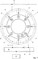
- FIG. 1 shows a highly schematic representation of a combustion chamber according to the invention with associated computer and control device.
- Corresponding Fig. 1 has a highly schematic combustion chamber 1, for example, such a gas turbine, a plurality of burners A to H, which are connected via controllable fuel valves 2 with a fuel supply 3, for example, a fuel line.
- a fuel supply 3 for example, a fuel line.
- the number of burners A to H here eight, purely by way of example, so that a combustion chamber 1 with more than eight or less than eight, but at least two burners should be enclosed by the invention.
- the burners A to H are arranged annularly in the illustrated embodiment and each have at least one optical measuring device 4 for detecting chemiluminescent radiation, in particular for detecting an OH chemiluminescence.
- the optical measuring devices 4 are connected via corresponding signal lines 5, in particular via a CAN-BUS 8, with a computer and control device 6.
- the fuel valves 2 connected via corresponding control lines 5 via the CAN-BUS 8 with the computer and control device 6.
- the optical measuring devices 4 detect light generated in the combustion chamber 1 due to chemical reactions and, according to a preferred embodiment, comprise an optical fiber. The optical fiber thereby falls the task of the light pipe between the burner and the actual optical measuring device.
- Such an optical fiber may, for example, be a glass fiber which conducts light signals from the burner to the optical measuring device 4.
- This offers the advantages that the optical measuring device 4 itself does not have to be arranged directly on the burner and is therefore exposed only to a significantly reduced temperature load, and a required space requirement of the optical fiber is significantly lower than the optical measuring device 4, so that they also at low Space can be arranged at almost any location in the vicinity of the burner.
- a pressure sensor 7 for detecting a pressure in the combustion chamber 1 is arranged and also connected via a corresponding signal line 5 'to an input side of the computer and control device 6.
- the pressure sensors can also be connected to the computer and control device 6 via the CAN bus 8.
- the computer and control device 6 is now designed such that it calculates a correlation between the chemiluminescent radiation of each burner A to H and the pressure in the combustion chamber 1 from the measured values arriving from the optical measuring devices 4 and the pressure sensor 7.
- the computer and control device 6 is connected to the fuel valves 2 associated with each burner A to H.
- the computer and control device 6 is designed such that it determines the burner or a burner group with the highest correlation between chemiluminescent radiation and combustion chamber pressure and the or the associated fuel valves controls such that the respective burner or the respective burner group more fuel is supplied.
- the computer and control device 6 opens the respectively associated fuel valve.
- a high correlation between the optical measured values and the combustion chamber pressure indicates a tendency to pulsate of the respective burner, which is to be reduced according to the invention. The pulsation of the flame on the one hand there is a risk that this extinguished and on the other hand reduces the efficiency of the gas turbine.
- pulsation-endangered burners can thus be identified. It is conceivable that the computer and control device 6 controls only a single burner with the highest correlation value by opening the associated fuel valve or a whole group of burners, which lie with their respective correlation values above a threshold.
- the summary of a burner group can either include, for example, the burner A and B, if these two have the two highest correlation values, or the burners can already be summarized in advance to certain groups, such as A, C, E and G, so that controlled them overall when only one of the said burners exceeds the correlation limit.
Landscapes
- Engineering & Computer Science (AREA)
- Chemical & Material Sciences (AREA)
- Combustion & Propulsion (AREA)
- Mechanical Engineering (AREA)
- General Engineering & Computer Science (AREA)
- Regulation And Control Of Combustion (AREA)
- Investigating, Analyzing Materials By Fluorescence Or Luminescence (AREA)
- Investigating Or Analysing Materials By The Use Of Chemical Reactions (AREA)
Claims (7)
- Chambre de combustion (1), plus particulièrement d'une turbine à gaz,- avec au moins deux brûleurs (A-H) qui sont reliés, par l'intermédiaire de vannes de carburant contrôlables (2) avec une alimentation en carburant (3),- moyennant quoi, à chaque brûleur (A-H) correspond au moins un dispositif de mesure optique (4) pour la mesure d'un rayonnement chimio-luminescent et à la chambre de combustion (1) correspond un capteur de pression (7) pour la mesure d'une pression,- avec un dispositif informatique de commande (6) qui est relié, d'une part avec les dispositifs de mesure optiques (4) et le capteur de pression (7) et, d'autre part avec les vannes de carburant contrôlables (2),- le dispositif informatique de commande (6) étant conçu de façon à ce qu'il calcule, à partir des valeurs de mesure provenant des dispositifs de mesure optiques (4) et du capteur de pression (7), une corrélation entre le rayonnement chimioluminescent de chacun des brûleurs (A-H) et la pression dans la chambre de combustion (1) et de façon à ce qu'il puisse calculer des valeurs de corrélation qui permettent un classement des brûleurs en brûleurs menacés par des pulsations et en brûleurs non menacés par des pulsations,- le dispositif informatique de commande (6) étant en outre conçu de façon à ce que celui-ci détermine le brûleur (A-H) ou un groupe de brûleurs avec la corrélation la plus forte et contrôle la ou les vanne(s) de carburant (2) correspondante(s) de façon à ce que plus de carburant soit introduit dans le brûleur (A-H) concerné ou dans le groupe de brûleurs concerné,caractérisée en ce que
le dispositif informatique de commande (6) est conçu de façon à contrôler, pour le respect d'une température de chambre de combustion globalement constante ou d'un débit de carburant globalement constant, les vannes de carburant (2) des brûleurs non menacés par des pulsations de manière inversement proportionnelle à celles des brûleurs menacés par des pulsations. - Chambre de combustion selon la revendication 1,
caractérisée en ce que
les dispositifs de mesure optiques (4) et/ou le capteur de pression (7) et/ou les vannes de carburant (2) sont reliés de manière communicante par l'intermédiaire d'un BUS, par exemple d'un CAN-BUS (8), avec le dispositif informatique de commande (6). - Chambre de combustion selon la revendication 1 ou 2,
caractérisée en ce que
les dispositifs de mesure optiques (4) sont conçus pour la mesure d'une chimioluminescence OH. - Chambre de combustion selon l'une des revendications 1 à 3,
caractérisée en ce que
les dispositifs de mesure optiques (4) comprennent une fibre optique. - Procédé de commande d'un processus de combustion avec au moins deux brûleurs (A-H), plus particulièrement dans une turbine à gaz, avec au moins les étapes suivantes :5.1 un dispositif de mesure optique (4), correspondant à un brûleur (A-H), mesure un rayonnement chimio-luminescent tandis qu'un capteur de pression (7) détermine simultanément une pression dans la chambre de combustion (1),5.2 un dispositif informatique de commande (6), relié côté entrée avec les dispositifs de mesure optiques (4) et le capteur de pression (7) et côté sortie avec les vannes de carburant contrôlables (2), calcule, à partir des valeurs de mesure provenant des dispositifs de mesure optiques (4) et du capteur de pression (7), une corrélation entre le rayonnement chimio-luminescent de chacun des brûleurs (A-H) et la pression dans la chambre de combustion (1) et calcule des valeurs de corrélation qui permettent un classement des brûleurs en brûleurs menacés par des pulsations et des brûleurs non menacés par des pulsations,5.3 le dispositif informatique de commande (6) détermine le brûleur (A-H) ou un groupe de brûleurs avec la corrélation la plus forte et ouvre la/les vanne(s) de carburant (2) correspondante(s),caractérisé en ce que5.4 pour le respect d'une température de chambre de combustion globalement constante ou d'un débit de carburant globalement constant, le dispositif informatique de commande (6) contrôle les vannes de carburant (2) des brûleurs non menacés par des pulsations de manière inversement proportionnelle à celles des brûleurs menacés par des pulsations.
- Procédé selon la revendication 5,
caractérisé en ce que
le dispositif informatique de commande (6) n'ouvre les vannes de carburant (2) qu'à partir d'une valeur de corrélation prédéfinie. - Procédé selon la revendication 5 ou 6,
caractérisé en ce que
le dispositif informatique de commande (6) ne contrôle les vannes de carburant (2) des brûleurs non menacés par des pulsations que dans la mesure où aucune pulsation ne survient dans ceux-ci.
Applications Claiming Priority (1)
| Application Number | Priority Date | Filing Date | Title |
|---|---|---|---|
| DE102006015230A DE102006015230A1 (de) | 2006-03-30 | 2006-03-30 | Brennkammer |
Publications (2)
| Publication Number | Publication Date |
|---|---|
| EP1840464A1 EP1840464A1 (fr) | 2007-10-03 |
| EP1840464B1 true EP1840464B1 (fr) | 2017-06-28 |
Family
ID=38197487
Family Applications (1)
| Application Number | Title | Priority Date | Filing Date |
|---|---|---|---|
| EP07101481.5A Not-in-force EP1840464B1 (fr) | 2006-03-30 | 2007-01-31 | Chambre de combustion |
Country Status (3)
| Country | Link |
|---|---|
| US (1) | US7901203B2 (fr) |
| EP (1) | EP1840464B1 (fr) |
| DE (1) | DE102006015230A1 (fr) |
Families Citing this family (11)
| Publication number | Priority date | Publication date | Assignee | Title |
|---|---|---|---|---|
| DE102007016018A1 (de) * | 2007-04-03 | 2008-10-09 | Sms Demag Ag | Brenneranordnung |
| DE102011117603A1 (de) | 2010-11-17 | 2012-05-24 | Alstom Technology Ltd. | Brennkammer und Verfahren zum Dämpfen von Pulsationen |
| DE102011118411A1 (de) * | 2010-12-09 | 2012-06-14 | Alstom Technology Ltd. | Brennkammer und Verfahren zum Liefern von Brennstoffen an eine Brennkammer |
| US9885609B2 (en) | 2014-05-23 | 2018-02-06 | United Technologies Corporation | Gas turbine engine optical system |
| US9964455B2 (en) | 2014-10-02 | 2018-05-08 | General Electric Company | Methods for monitoring strain and temperature in a hot gas path component |
| US9395301B2 (en) | 2014-10-02 | 2016-07-19 | General Electric Company | Methods for monitoring environmental barrier coatings |
| US11156164B2 (en) | 2019-05-21 | 2021-10-26 | General Electric Company | System and method for high frequency accoustic dampers with caps |
| US11174792B2 (en) | 2019-05-21 | 2021-11-16 | General Electric Company | System and method for high frequency acoustic dampers with baffles |
| EP3757460B1 (fr) * | 2019-06-28 | 2022-06-22 | Ansaldo Energia Switzerland AG | Moteur à turbine à gaz comportant une protection active contre l'extinction de flamme et procédé de fonctionnement d'un moteur à turbine à gaz |
| CN113915007B (zh) * | 2021-11-11 | 2024-06-11 | 西安热工研究院有限公司 | 一种新型燃气轮机燃烧压力脉动控制系统 |
| US20240271784A1 (en) * | 2023-02-15 | 2024-08-15 | Raytheon Technologies Corporation | Optical detection system for a gas turbine engine combustion assembly |
Citations (1)
| Publication number | Priority date | Publication date | Assignee | Title |
|---|---|---|---|---|
| US20050056024A1 (en) * | 2002-10-30 | 2005-03-17 | Lieuwen Tim C. | Systems and methods for detection and control of blowout precursors in combustors using acoustical and optical sensing |
Family Cites Families (24)
| Publication number | Priority date | Publication date | Assignee | Title |
|---|---|---|---|---|
| GB1162824A (en) * | 1965-09-07 | 1969-08-27 | Honeywell Inc | Flame Failure Safety System |
| US4913647A (en) * | 1986-03-19 | 1990-04-03 | Honeywell Inc. | Air fuel ratio control |
| JPH01244214A (ja) * | 1988-03-25 | 1989-09-28 | Agency Of Ind Science & Technol | バーナ運転空気比の監視制御方法および装置 |
| US5487266A (en) * | 1992-05-05 | 1996-01-30 | General Electric Company | Combustion control for producing low NOx emissions through use of flame spectroscopy |
| US5249954A (en) * | 1992-07-07 | 1993-10-05 | Electric Power Research Institute, Inc. | Integrated imaging sensor/neural network controller for combustion systems |
| FR2711769B1 (fr) * | 1993-10-29 | 1995-12-08 | Air Liquide | Procédé de combustion dans un four industriel. |
| US5544478A (en) * | 1994-11-15 | 1996-08-13 | General Electric Company | Optical sensing of combustion dynamics |
| US5706643A (en) * | 1995-11-14 | 1998-01-13 | United Technologies Corporation | Active gas turbine combustion control to minimize nitrous oxide emissions |
| US5755819A (en) * | 1996-05-24 | 1998-05-26 | General Electric Company | Photodiode array for analysis of multi-burner gas combustors |
| US5978525A (en) * | 1996-06-24 | 1999-11-02 | General Electric Company | Fiber optic sensors for gas turbine control |
| US6464489B1 (en) * | 1997-11-24 | 2002-10-15 | Alstom | Method and apparatus for controlling thermoacoustic vibrations in a combustion system |
| EP0918152A1 (fr) | 1997-11-24 | 1999-05-26 | Abb Research Ltd. | Procédé et dispositif pour contrÔler les vibrations thermoacoustiques dans les chambres de combustion |
| DE19928226A1 (de) | 1999-05-07 | 2001-02-01 | Abb Alstom Power Ch Ag | Verfahren zur Unterdrückung bzw. Kontrolle von thermoakustischen Schwingungen in einem Verbrennungs-System sowie Verbrennungssystem zur Durchführung des Verfahrens |
| US6468069B2 (en) * | 1999-10-25 | 2002-10-22 | Jerome H. Lemelson | Automatically optimized combustion control |
| US6702571B2 (en) * | 2001-09-05 | 2004-03-09 | Gas Technology Institute | Flex-flame burner and self-optimizing combustion system |
| US6742341B2 (en) * | 2002-07-16 | 2004-06-01 | Siemens Westinghouse Power Corporation | Automatic combustion control for a gas turbine |
| DE10333671A1 (de) * | 2003-07-24 | 2005-08-04 | Alstom Technology Ltd | Verfahren zur Reduktion der Nox-Emissionen einer mehrere Brenner umfassenden Brenneranordnung sowie Brenneranordnung zur Durchführung des Verfahrens |
| EP1709365B1 (fr) * | 2004-01-12 | 2021-08-18 | Combustion Science & Engineering, Inc. | Systeme et procede de stabilisation et de regulation de flammes |
| US7194382B2 (en) * | 2004-02-06 | 2007-03-20 | Georgia Tech Research Corporation | Systems and methods for detection of combustor stability margin |
| DE102004015186A1 (de) * | 2004-03-29 | 2005-10-20 | Alstom Technology Ltd Baden | Gasturbinen-Brennkammer und zugehöriges Betriebsverfahren |
| DE102004015187A1 (de) * | 2004-03-29 | 2005-10-20 | Alstom Technology Ltd Baden | Brennkammer für eine Gasturbine und zugehöriges Betriebsverfahren |
| US7334413B2 (en) * | 2004-05-07 | 2008-02-26 | Rosemount Aerospace Inc. | Apparatus, system and method for observing combustion conditions in a gas turbine engine |
| US7484369B2 (en) | 2004-05-07 | 2009-02-03 | Rosemount Aerospace Inc. | Apparatus for observing combustion conditions in a gas turbine engine |
| DE102004036911A1 (de) * | 2004-07-29 | 2006-03-23 | Alstom Technology Ltd | Betriebsverfahren für eine Feuerungsanlage |
-
2006
- 2006-03-30 DE DE102006015230A patent/DE102006015230A1/de not_active Withdrawn
-
2007
- 2007-01-31 EP EP07101481.5A patent/EP1840464B1/fr not_active Not-in-force
- 2007-02-20 US US11/676,584 patent/US7901203B2/en not_active Expired - Fee Related
Patent Citations (1)
| Publication number | Priority date | Publication date | Assignee | Title |
|---|---|---|---|---|
| US20050056024A1 (en) * | 2002-10-30 | 2005-03-17 | Lieuwen Tim C. | Systems and methods for detection and control of blowout precursors in combustors using acoustical and optical sensing |
Also Published As
| Publication number | Publication date |
|---|---|
| EP1840464A1 (fr) | 2007-10-03 |
| US20070224559A1 (en) | 2007-09-27 |
| DE102006015230A1 (de) | 2007-10-18 |
| US7901203B2 (en) | 2011-03-08 |
Similar Documents
| Publication | Publication Date | Title |
|---|---|---|
| EP1840464B1 (fr) | Chambre de combustion | |
| EP0915406B1 (fr) | Méthode pour surveiller le système d'alimentation d'une turbine à gaz ayant des brûleurs multiples et dispositif pour la mise en oeuvre de cette méthode | |
| EP2171239B1 (fr) | Procédé pour faire fonctionner un dispositif de combustion ainsi que dispositif de combustion pour mettre en oeuvre ce procédé | |
| EP1621811B1 (fr) | Procédé de fonctionnement pour un dispositif de combustion | |
| DE4417199C2 (de) | Vorrichtung zum Steuern von Gasturbinen | |
| EP3301362A1 (fr) | Régulation d'écoulements turbulents | |
| EP1840465A2 (fr) | Système comportant des brûleurs à injection de carburant étagée | |
| EP1746345B1 (fr) | Procédé de fonctionnement d'un brûleur à gaz | |
| EP0969192B1 (fr) | Méthode pour égaliser la distribution de carburant dans une turbine à gaz avec plusieurs brûleurs | |
| EP1971804B1 (fr) | Procédé de fonctionnement d'un foyer | |
| DE102005011287A1 (de) | Verfahren sowie eine Vorrichtung zum Betreiben wenigstens eines Brenners zur Befeuerung der Brennkammer einer Wärmekraftmaschine | |
| DE102018203936B4 (de) | Abgasanlage für eine Brennkraftmaschine und entsprechende Brennkraftmaschine | |
| EP3369994B1 (fr) | Procédé de détermination de l'origine d'un défaut d'allumage d'un brûleur d'une chaudière | |
| WO2020221540A1 (fr) | Réduction d'oxydes d'azote dans le flux de gaz d'échappement d'une installation de calcination avec un catalyseur scr | |
| DE102015110402A1 (de) | Düsenbrennersystem | |
| EP4075061B1 (fr) | Dispositif de diminution des conséquences d'un retour de flamme dans un brûleur à prémélange d'un chauffage | |
| EP4045851B1 (fr) | Procédé de commande d'un dispositif de combustion | |
| EP4155610B1 (fr) | Procédé de surveillance de l'allumage d'une flamme d'un brûleur | |
| EP4215815A1 (fr) | Procédé de fonctionnement d'un appareil de chauffage produisant de la flamme d'une installation de chauffage, programme de com-puter, support de stockage, appareil de commande et utilisation d'un débit d'une installation de chauffage et d'ionisation | |
| EP4148325A1 (fr) | Procédé et dispositif de détection de la présence des flammes dans une chambre de combustion lors d'une modulation d'un appareil chauffant | |
| EP4145047A1 (fr) | Procédé et dispositif de détection de l'allumage de flammes dans une chambre de combustion d'un appareil chauffant, produit programme informatique et utilisation | |
| EP4386261A1 (fr) | Procédé de fonctionnement d'un appareil de chauffage, programme informatique, appareil de réglage et de commande et appareil de chauffage | |
| EP4336101A1 (fr) | Dispositif de détection d'un retour d'allumage dans un appareil de chauffage | |
| EP4155608A1 (fr) | Procédé de détection de l'extinction d'une flamme d'un brûleur | |
| EP4336100A1 (fr) | Procédé de détection d'un retour de flamme dans un appareil de chauffage, appareil de réglage et de commande, appareil de chauffage et programme informatique |
Legal Events
| Date | Code | Title | Description |
|---|---|---|---|
| PUAI | Public reference made under article 153(3) epc to a published international application that has entered the european phase |
Free format text: ORIGINAL CODE: 0009012 |
|
| AK | Designated contracting states |
Kind code of ref document: A1 Designated state(s): AT BE BG CH CY CZ DE DK EE ES FI FR GB GR HU IE IS IT LI LT LU LV MC NL PL PT RO SE SI SK TR |
|
| AX | Request for extension of the european patent |
Extension state: AL BA HR MK YU |
|
| 17P | Request for examination filed |
Effective date: 20080326 |
|
| 17Q | First examination report despatched |
Effective date: 20080509 |
|
| AKX | Designation fees paid |
Designated state(s): AT BE BG CH CY CZ DE DK EE ES FI FR GB GR HU IE IS IT LI LT LU LV MC NL PL PT RO SE SI SK TR |
|
| RAP1 | Party data changed (applicant data changed or rights of an application transferred) |
Owner name: GENERAL ELECTRIC TECHNOLOGY GMBH |
|
| GRAP | Despatch of communication of intention to grant a patent |
Free format text: ORIGINAL CODE: EPIDOSNIGR1 |
|
| INTG | Intention to grant announced |
Effective date: 20170117 |
|
| GRAS | Grant fee paid |
Free format text: ORIGINAL CODE: EPIDOSNIGR3 |
|
| GRAA | (expected) grant |
Free format text: ORIGINAL CODE: 0009210 |
|
| RAP1 | Party data changed (applicant data changed or rights of an application transferred) |
Owner name: ANSALDO ENERGIA SWITZERLAND AG |
|
| AK | Designated contracting states |
Kind code of ref document: B1 Designated state(s): AT BE BG CH CY CZ DE DK EE ES FI FR GB GR HU IE IS IT LI LT LU LV MC NL PL PT RO SE SI SK TR |
|
| REG | Reference to a national code |
Ref country code: GB Ref legal event code: FG4D Free format text: NOT ENGLISH |
|
| REG | Reference to a national code |
Ref country code: CH Ref legal event code: EP |
|
| REG | Reference to a national code |
Ref country code: AT Ref legal event code: REF Ref document number: 905209 Country of ref document: AT Kind code of ref document: T Effective date: 20170715 |
|
| REG | Reference to a national code |
Ref country code: IE Ref legal event code: FG4D Free format text: LANGUAGE OF EP DOCUMENT: GERMAN |
|
| REG | Reference to a national code |
Ref country code: DE Ref legal event code: R096 Ref document number: 502007015726 Country of ref document: DE |
|
| PG25 | Lapsed in a contracting state [announced via postgrant information from national office to epo] |
Ref country code: FI Free format text: LAPSE BECAUSE OF FAILURE TO SUBMIT A TRANSLATION OF THE DESCRIPTION OR TO PAY THE FEE WITHIN THE PRESCRIBED TIME-LIMIT Effective date: 20170628 Ref country code: GR Free format text: LAPSE BECAUSE OF FAILURE TO SUBMIT A TRANSLATION OF THE DESCRIPTION OR TO PAY THE FEE WITHIN THE PRESCRIBED TIME-LIMIT Effective date: 20170929 Ref country code: LT Free format text: LAPSE BECAUSE OF FAILURE TO SUBMIT A TRANSLATION OF THE DESCRIPTION OR TO PAY THE FEE WITHIN THE PRESCRIBED TIME-LIMIT Effective date: 20170628 |
|
| REG | Reference to a national code |
Ref country code: NL Ref legal event code: MP Effective date: 20170628 |
|
| REG | Reference to a national code |
Ref country code: LT Ref legal event code: MG4D |
|
| PG25 | Lapsed in a contracting state [announced via postgrant information from national office to epo] |
Ref country code: SE Free format text: LAPSE BECAUSE OF FAILURE TO SUBMIT A TRANSLATION OF THE DESCRIPTION OR TO PAY THE FEE WITHIN THE PRESCRIBED TIME-LIMIT Effective date: 20170628 Ref country code: NL Free format text: LAPSE BECAUSE OF FAILURE TO SUBMIT A TRANSLATION OF THE DESCRIPTION OR TO PAY THE FEE WITHIN THE PRESCRIBED TIME-LIMIT Effective date: 20170628 Ref country code: LV Free format text: LAPSE BECAUSE OF FAILURE TO SUBMIT A TRANSLATION OF THE DESCRIPTION OR TO PAY THE FEE WITHIN THE PRESCRIBED TIME-LIMIT Effective date: 20170628 Ref country code: BG Free format text: LAPSE BECAUSE OF FAILURE TO SUBMIT A TRANSLATION OF THE DESCRIPTION OR TO PAY THE FEE WITHIN THE PRESCRIBED TIME-LIMIT Effective date: 20170928 |
|
| REG | Reference to a national code |
Ref country code: FR Ref legal event code: PLFP Year of fee payment: 12 |
|
| PG25 | Lapsed in a contracting state [announced via postgrant information from national office to epo] |
Ref country code: RO Free format text: LAPSE BECAUSE OF FAILURE TO SUBMIT A TRANSLATION OF THE DESCRIPTION OR TO PAY THE FEE WITHIN THE PRESCRIBED TIME-LIMIT Effective date: 20170628 Ref country code: EE Free format text: LAPSE BECAUSE OF FAILURE TO SUBMIT A TRANSLATION OF THE DESCRIPTION OR TO PAY THE FEE WITHIN THE PRESCRIBED TIME-LIMIT Effective date: 20170628 Ref country code: CZ Free format text: LAPSE BECAUSE OF FAILURE TO SUBMIT A TRANSLATION OF THE DESCRIPTION OR TO PAY THE FEE WITHIN THE PRESCRIBED TIME-LIMIT Effective date: 20170628 Ref country code: SK Free format text: LAPSE BECAUSE OF FAILURE TO SUBMIT A TRANSLATION OF THE DESCRIPTION OR TO PAY THE FEE WITHIN THE PRESCRIBED TIME-LIMIT Effective date: 20170628 |
|
| PG25 | Lapsed in a contracting state [announced via postgrant information from national office to epo] |
Ref country code: IS Free format text: LAPSE BECAUSE OF FAILURE TO SUBMIT A TRANSLATION OF THE DESCRIPTION OR TO PAY THE FEE WITHIN THE PRESCRIBED TIME-LIMIT Effective date: 20171028 Ref country code: ES Free format text: LAPSE BECAUSE OF FAILURE TO SUBMIT A TRANSLATION OF THE DESCRIPTION OR TO PAY THE FEE WITHIN THE PRESCRIBED TIME-LIMIT Effective date: 20170628 Ref country code: PL Free format text: LAPSE BECAUSE OF FAILURE TO SUBMIT A TRANSLATION OF THE DESCRIPTION OR TO PAY THE FEE WITHIN THE PRESCRIBED TIME-LIMIT Effective date: 20170628 |
|
| REG | Reference to a national code |
Ref country code: DE Ref legal event code: R097 Ref document number: 502007015726 Country of ref document: DE |
|
| PG25 | Lapsed in a contracting state [announced via postgrant information from national office to epo] |
Ref country code: DK Free format text: LAPSE BECAUSE OF FAILURE TO SUBMIT A TRANSLATION OF THE DESCRIPTION OR TO PAY THE FEE WITHIN THE PRESCRIBED TIME-LIMIT Effective date: 20170628 |
|
| PGFP | Annual fee paid to national office [announced via postgrant information from national office to epo] |
Ref country code: DE Payment date: 20180122 Year of fee payment: 12 Ref country code: GB Payment date: 20180119 Year of fee payment: 12 |
|
| PLBE | No opposition filed within time limit |
Free format text: ORIGINAL CODE: 0009261 |
|
| STAA | Information on the status of an ep patent application or granted ep patent |
Free format text: STATUS: NO OPPOSITION FILED WITHIN TIME LIMIT |
|
| PGFP | Annual fee paid to national office [announced via postgrant information from national office to epo] |
Ref country code: FR Payment date: 20180119 Year of fee payment: 12 Ref country code: IT Payment date: 20180129 Year of fee payment: 12 |
|
| 26N | No opposition filed |
Effective date: 20180329 |
|
| PG25 | Lapsed in a contracting state [announced via postgrant information from national office to epo] |
Ref country code: SI Free format text: LAPSE BECAUSE OF FAILURE TO SUBMIT A TRANSLATION OF THE DESCRIPTION OR TO PAY THE FEE WITHIN THE PRESCRIBED TIME-LIMIT Effective date: 20170628 |
|
| REG | Reference to a national code |
Ref country code: CH Ref legal event code: PL |
|
| PG25 | Lapsed in a contracting state [announced via postgrant information from national office to epo] |
Ref country code: LU Free format text: LAPSE BECAUSE OF NON-PAYMENT OF DUE FEES Effective date: 20180131 |
|
| REG | Reference to a national code |
Ref country code: IE Ref legal event code: MM4A |
|
| REG | Reference to a national code |
Ref country code: BE Ref legal event code: MM Effective date: 20180131 |
|
| PG25 | Lapsed in a contracting state [announced via postgrant information from national office to epo] |
Ref country code: BE Free format text: LAPSE BECAUSE OF NON-PAYMENT OF DUE FEES Effective date: 20180131 Ref country code: LI Free format text: LAPSE BECAUSE OF NON-PAYMENT OF DUE FEES Effective date: 20180131 Ref country code: CH Free format text: LAPSE BECAUSE OF NON-PAYMENT OF DUE FEES Effective date: 20180131 |
|
| PG25 | Lapsed in a contracting state [announced via postgrant information from national office to epo] |
Ref country code: IE Free format text: LAPSE BECAUSE OF NON-PAYMENT OF DUE FEES Effective date: 20180131 |
|
| REG | Reference to a national code |
Ref country code: AT Ref legal event code: MM01 Ref document number: 905209 Country of ref document: AT Kind code of ref document: T Effective date: 20180131 |
|
| PG25 | Lapsed in a contracting state [announced via postgrant information from national office to epo] |
Ref country code: AT Free format text: LAPSE BECAUSE OF NON-PAYMENT OF DUE FEES Effective date: 20180131 |
|
| PG25 | Lapsed in a contracting state [announced via postgrant information from national office to epo] |
Ref country code: MC Free format text: LAPSE BECAUSE OF FAILURE TO SUBMIT A TRANSLATION OF THE DESCRIPTION OR TO PAY THE FEE WITHIN THE PRESCRIBED TIME-LIMIT Effective date: 20170628 |
|
| REG | Reference to a national code |
Ref country code: DE Ref legal event code: R119 Ref document number: 502007015726 Country of ref document: DE |
|
| GBPC | Gb: european patent ceased through non-payment of renewal fee |
Effective date: 20190131 |
|
| PG25 | Lapsed in a contracting state [announced via postgrant information from national office to epo] |
Ref country code: DE Free format text: LAPSE BECAUSE OF NON-PAYMENT OF DUE FEES Effective date: 20190801 Ref country code: FR Free format text: LAPSE BECAUSE OF NON-PAYMENT OF DUE FEES Effective date: 20190131 |
|
| PG25 | Lapsed in a contracting state [announced via postgrant information from national office to epo] |
Ref country code: GB Free format text: LAPSE BECAUSE OF NON-PAYMENT OF DUE FEES Effective date: 20190131 |
|
| PG25 | Lapsed in a contracting state [announced via postgrant information from national office to epo] |
Ref country code: IT Free format text: LAPSE BECAUSE OF NON-PAYMENT OF DUE FEES Effective date: 20190131 |
|
| PG25 | Lapsed in a contracting state [announced via postgrant information from national office to epo] |
Ref country code: TR Free format text: LAPSE BECAUSE OF FAILURE TO SUBMIT A TRANSLATION OF THE DESCRIPTION OR TO PAY THE FEE WITHIN THE PRESCRIBED TIME-LIMIT Effective date: 20170628 |
|
| PG25 | Lapsed in a contracting state [announced via postgrant information from national office to epo] |
Ref country code: HU Free format text: LAPSE BECAUSE OF FAILURE TO SUBMIT A TRANSLATION OF THE DESCRIPTION OR TO PAY THE FEE WITHIN THE PRESCRIBED TIME-LIMIT; INVALID AB INITIO Effective date: 20070131 Ref country code: PT Free format text: LAPSE BECAUSE OF FAILURE TO SUBMIT A TRANSLATION OF THE DESCRIPTION OR TO PAY THE FEE WITHIN THE PRESCRIBED TIME-LIMIT Effective date: 20170628 |
|
| PG25 | Lapsed in a contracting state [announced via postgrant information from national office to epo] |
Ref country code: CY Free format text: LAPSE BECAUSE OF FAILURE TO SUBMIT A TRANSLATION OF THE DESCRIPTION OR TO PAY THE FEE WITHIN THE PRESCRIBED TIME-LIMIT Effective date: 20170628 |