EP1836484B9 - Messvorrichtung und -verfahren zur erkennung von fremdkörpern in tabak - Google Patents
Messvorrichtung und -verfahren zur erkennung von fremdkörpern in tabak Download PDFInfo
- Publication number
- EP1836484B9 EP1836484B9 EP05821673.0A EP05821673A EP1836484B9 EP 1836484 B9 EP1836484 B9 EP 1836484B9 EP 05821673 A EP05821673 A EP 05821673A EP 1836484 B9 EP1836484 B9 EP 1836484B9
- Authority
- EP
- European Patent Office
- Prior art keywords
- measuring
- tobacco
- capacitor
- frequency
- measuring apparatus
- Prior art date
- Legal status (The legal status is an assumption and is not a legal conclusion. Google has not performed a legal analysis and makes no representation as to the accuracy of the status listed.)
- Active
Links
- 241000208125 Nicotiana Species 0.000 title claims description 44
- 235000002637 Nicotiana tabacum Nutrition 0.000 title claims description 44
- 238000000034 method Methods 0.000 title claims description 14
- 239000003990 capacitor Substances 0.000 claims description 70
- 238000005259 measurement Methods 0.000 claims description 23
- 238000011156 evaluation Methods 0.000 claims description 18
- 230000001419 dependent effect Effects 0.000 claims description 11
- 238000001514 detection method Methods 0.000 claims description 10
- 239000000463 material Substances 0.000 claims description 9
- 238000012545 processing Methods 0.000 claims description 8
- 238000005070 sampling Methods 0.000 claims description 6
- 230000010363 phase shift Effects 0.000 claims description 5
- 239000011248 coating agent Substances 0.000 claims description 4
- 238000000576 coating method Methods 0.000 claims description 4
- 239000003989 dielectric material Substances 0.000 claims description 2
- 239000002184 metal Substances 0.000 claims description 2
- 229910052751 metal Inorganic materials 0.000 claims description 2
- 230000005672 electromagnetic field Effects 0.000 claims 2
- 239000000047 product Substances 0.000 description 29
- 230000006870 function Effects 0.000 description 3
- 230000010355 oscillation Effects 0.000 description 3
- 238000012360 testing method Methods 0.000 description 3
- 229920000742 Cotton Polymers 0.000 description 2
- 235000019504 cigarettes Nutrition 0.000 description 2
- 238000004590 computer program Methods 0.000 description 2
- 230000005684 electric field Effects 0.000 description 2
- 230000003993 interaction Effects 0.000 description 2
- 230000015654 memory Effects 0.000 description 2
- 239000012811 non-conductive material Substances 0.000 description 2
- 230000035945 sensitivity Effects 0.000 description 2
- URAYPUMNDPQOKB-UHFFFAOYSA-N triacetin Chemical compound CC(=O)OCC(OC(C)=O)COC(C)=O URAYPUMNDPQOKB-UHFFFAOYSA-N 0.000 description 2
- 239000006094 Zerodur Substances 0.000 description 1
- 229910002056 binary alloy Inorganic materials 0.000 description 1
- 238000007664 blowing Methods 0.000 description 1
- 239000006227 byproduct Substances 0.000 description 1
- 238000011109 contamination Methods 0.000 description 1
- 230000000694 effects Effects 0.000 description 1
- 238000005516 engineering process Methods 0.000 description 1
- 239000012530 fluid Substances 0.000 description 1
- 239000001087 glyceryl triacetate Substances 0.000 description 1
- 235000013773 glyceryl triacetate Nutrition 0.000 description 1
- PCHJSUWPFVWCPO-UHFFFAOYSA-N gold Chemical compound [Au] PCHJSUWPFVWCPO-UHFFFAOYSA-N 0.000 description 1
- 239000010931 gold Substances 0.000 description 1
- 229910052737 gold Inorganic materials 0.000 description 1
- 239000002923 metal particle Substances 0.000 description 1
- 230000002093 peripheral effect Effects 0.000 description 1
- 239000010453 quartz Substances 0.000 description 1
- 230000005855 radiation Effects 0.000 description 1
- 235000015067 sauces Nutrition 0.000 description 1
- VYPSYNLAJGMNEJ-UHFFFAOYSA-N silicon dioxide Inorganic materials O=[Si]=O VYPSYNLAJGMNEJ-UHFFFAOYSA-N 0.000 description 1
- 239000007787 solid Substances 0.000 description 1
- 239000000126 substance Substances 0.000 description 1
- 229960002622 triacetin Drugs 0.000 description 1
- 238000011144 upstream manufacturing Methods 0.000 description 1
- 238000007740 vapor deposition Methods 0.000 description 1
Images

Classifications
-
- A—HUMAN NECESSITIES
- A24—TOBACCO; CIGARS; CIGARETTES; SIMULATED SMOKING DEVICES; SMOKERS' REQUISITES
- A24C—MACHINES FOR MAKING CIGARS OR CIGARETTES
- A24C5/00—Making cigarettes; Making tipping materials for, or attaching filters or mouthpieces to, cigars or cigarettes
- A24C5/32—Separating, ordering, counting or examining cigarettes; Regulating the feeding of tobacco according to rod or cigarette condition
- A24C5/34—Examining cigarettes or the rod, e.g. for regulating the feeding of tobacco; Removing defective cigarettes
- A24C5/3412—Examining cigarettes or the rod, e.g. for regulating the feeding of tobacco; Removing defective cigarettes by means of light, radiation or electrostatic fields
-
- G—PHYSICS
- G01—MEASURING; TESTING
- G01N—INVESTIGATING OR ANALYSING MATERIALS BY DETERMINING THEIR CHEMICAL OR PHYSICAL PROPERTIES
- G01N27/00—Investigating or analysing materials by the use of electric, electrochemical, or magnetic means
- G01N27/02—Investigating or analysing materials by the use of electric, electrochemical, or magnetic means by investigating impedance
- G01N27/22—Investigating or analysing materials by the use of electric, electrochemical, or magnetic means by investigating impedance by investigating capacitance
- G01N27/228—Circuits therefor
-
- G—PHYSICS
- G01—MEASURING; TESTING
- G01N—INVESTIGATING OR ANALYSING MATERIALS BY DETERMINING THEIR CHEMICAL OR PHYSICAL PROPERTIES
- G01N22/00—Investigating or analysing materials by the use of microwaves or radio waves, i.e. electromagnetic waves with a wavelength of one millimetre or more
- G01N22/04—Investigating moisture content
Definitions
- the invention relates to a measuring device for detecting foreign bodies in tobacco, according to the preamble of claim 1.
- the invention further relates to a corresponding measuring method.
- the font shows US 4114090 a unit for determining the moisture content of tobacco, wherein the material whose moisture content is to be determined is guided here by a capacity which is part of an RC network.
- document EP 924 513 A1 shows an apparatus and a method for determining proportions of solids in a test material by the test material is exposed in a measuring capacitor to an alternating electric field, so that the dielectric properties of the test material can be determined by measurable values such as current, voltage and phase angle.
- the US3996942 discloses an apparatus and method for determining density along a cigarette rod passed through a measuring capacitor.
- the measuring capacitor of the FIG. 2 consists of two tubular electrodes, both grounded, and an ungrounded ring electrode between the two grounded tubular electrodes.
- the object of the present invention is to provide a structurally simple measuring device for foreign body determination with high accuracy.
- the invention achieves this object with the features of claims 1 and 20.
- a capacitor in particular instead of a microwave resonator, and a high-frequency field below the microwave range, the circuit complexity can be significantly reduced.
- a more homogeneous field can be generated in the product space by means of a capacitor than by means of a microwave resonator in which the electric field strength disappears on the peripheral wall.
- the term "foreign body” means any other type of material that is undesirably present in the binary system to be tested.
- the dual-substance system to be tested is particularly of tobacco and moisture (or sauce), or filter material and triacetin.
- the invention then differs from known capacitive measuring devices in High frequency range for detection of mass or density errors, for example in tobacco, which only affect the two-component system of product and moisture. Due to its differing dielectric properties, a foreign body in a certain way influences the high-frequency field and therefore the measured variables determined. By suitable evaluation in the evaluation device, a foreign body in the product can be recognized from the measured variables determined, in particular if the course of a measured variable shows a deviation caused by the foreign body.
- high frequency basically means, in contrast to the microwave range, fields with a frequency below 100 MHz, preferably below 10 MHz. As a rule, the frequency is more than 100 kHz. In a preferred variant of the invention, a high-frequency field with a frequency below 5 MHz, preferably below 1 MHz is used. This is surprising, since it is known with respect to the measurement of the moisture and / or density of the product that at lower frequencies a sufficiently accurate measurement is possible only in an increasingly limited range, so that for tobacco a measuring frequency of at least 5 MHz as appropriate applies. For the determination of foreign bodies in tobacco, however, results in a greater sensitivity especially at lower frequencies.
- the measuring capacitor is not frequency-determining part of a measuring resonant circuit, can be dispensed with the use of a temperature sensitive sensitive resonant circuit coil.
- “Substantially” means that resonant field components are not excluded as long as the measurement principle is essentially based on a traveling wave. Since no resonance condition for a measuring circuit is respected must be, the measuring capacitor may have a relation to the prior art reduced capacity of preferably less than 10 pF, which reduces the effort and size.
- the described preferred embodiment therefore differs from known capacitive measuring devices in the high frequency range for detecting mass or density errors in tobacco, in which a measuring capacitor and a coil are connected as frequency-determining parts in a high-frequency resonant circuit, wherein as measured variables, for example, those influenced by the product Resonance frequency and resonance amplitude of the high frequency field can be determined.
- the foreign object recognition is preferably based on the fact that two independent measured variables, in particular a measured variable dependent on the capacitance of the measuring capacitor and a measured variable dependent on the loss factor of the measuring capacitor, are in a different relationship to the expected curve.
- the measurement of two independent measures is provided.
- two measured variables dependent on the amplitude and the phase of the high-frequency wave are determined. Basically, therefore, the generation of a high frequency wave is sufficient, which reduces the effort compared to such devices, which are based on the use of multiple high frequency waves of different high frequencies.
- the determination of two independent measured quantities is not mandatory; It is also conceivable to carry out a foreign body detection from the course of only one measured variable.
- the part of the circuit device serving to determine the measured variables is usually connected downstream of the actual measuring circuit which comprises the measuring capacitor. While the measuring circuit usually has an output for the affected by the product high-frequency field, the Meßierenbeticians drove usually one of the number of measured variables to be determined corresponding number of outputs, preferably therefore two outputs. It is also possible that the measuring circuit and the Meß istnbeéesseinhchtung form a unit.
- the measured variable determining device is connected upstream of the actual evaluation device for foreign body recognition by evaluating the measuring signal. It is also possible that the measured variable determining device and the evaluation device form a unit.
- the portion of the circuit device serving to determine the measured quantity or measured variables is designed to be digital-electronic.
- a particularly simple and therefore preferred method is based on the orthogonality of the sine and cosine components and comprises the measurement of a discrete number of n measured values, for example voltage values, over each oscillation period of the high-frequency field, separate multiplication of the n measured values with corresponding sine and cosine values and separate summation of these sine and cosine products.
- the sums obtained represent the measured variables or can be further processed to determine the measured variables.
- the measurement capacitor comprising part of the circuit device is an RC element, preferably with an operational amplifier. This is preferably an RC differentiator, but it can also be used, for example, an RC integrator.
- parts of the sensor are made of a material with a low coefficient of thermal expansion in order to minimize the effects of temperature fluctuations on the measurement accuracy.
- the sensor may have an additional means for keeping constant the temperature of the measuring capacitor.
- An additional device for measuring the temperature of the measuring capacitor for example a temperature sensor, is conceivable in order to be able to correct the measuring signal accordingly.
- the capacitor is arranged substantially perpendicular to the transport direction of the product.
- the capacitor plates are arranged perpendicular to the transport direction. This makes it possible to arrange the electrodes at a short distance from each other, for example below the strand thickness of the product. As a result, an improved resolution with respect to the foreign body recognition in the longitudinal direction, and thus an increase in the detection sensitivity, be achieved.
- the sensor is designed to pass the product through the space formed between the electrodes of the measuring capacitor in order to allow as complete and uniform detection of the product as possible.
- An embodiment not covered by the invention relates to the measurement of a relatively wide product, for example a tobacco or tow sheet or a cotton fleece, or a plurality of adjacent product strands.
- the sensor comprises a plurality of measuring capacitors arranged across the width of the product. This arrangement allows in a simple way a lateral position determination of a detected foreign body.
- the electrodes connected to the high-frequency field generating means are kept at the same potential, for example simply short-circuited, in order to minimize crosstalk between the measuring capacitors.
- the other electrodes are also preferably kept virtually at the same potential by means of inverting operational amplifiers.
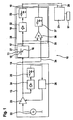
- the capacitive measuring device 10 comprises a high-frequency generating device 13 for generating a high-frequency wave, which is fed via an input line 14 to a circuit device 28.
- the circuit device 28 comprises a measuring capacitor 11, through which the tobacco to be measured, in the present case strand-shaped tobacco 12 is guided.
- the high frequency wave generated by the high frequency generator 13 is conducted to an electrode 15 of the measuring capacitor 11 to generate therein a high frequency field interacting with the tobacco 12.
- the expired by the other electrode 16 of the measuring capacitor 11, influenced by the tobacco 12 high frequency wave is processed by the circuit means 28 to at least one, preferably two independent, on the amplitude and / or the phase of the tobacco 12 influenced by the high-frequency wave dependent measured variables to determine. These are preferably two measured variables which depend on the capacitance and the loss factor of the measuring capacitor 11. Measurement signals corresponding to the measured variables are sent to the evaluation device 21, for example a correspondingly programmed computer.
- an undesirable foreign body 90 may occur, for example, a plastic or metal particles. Due to deviating dielectric properties of the foreign body 90 affects in a certain way the amplitude and phase of the high frequency wave and thereby also the measured quantities determined.
- a foreign body 90 can be detected in the product 12 from the measured variables determined, in particular if the course of a measured variable shows a deviation caused by the foreign body 90. For example, from a foreign body 90 spikes in a trace be caused; the evaluation device is then expediently set up to detect such fluctuations in the measurement curve. Proven for foreign body detection is the evaluation of the ratio of two independent measured variables.
- the evaluation device 21 can optionally control a removal means 91, for example a blowing nozzle, for removing a part of the tobacco 12 in which a foreign body 90 is detected.
- the embodiment according to Fig. 1 relates to a substantially analog measuring device.
- the high frequency generator 13 includes a harmonic oscillator 22 for generating a high frequency cell.
- the voltage amplitude U c of the generated high-frequency wave is preferably kept constant by means of a control device 23-26 in order to allow a measurement uninfluenced by fluctuations in the input amplitude.
- the high frequency wave generated by the harmonic oscillator 22 is fed to a controllable amplifier 23.
- the output signal of the amplifier 23 is fed to a rectifier 24, whose output signal is passed through the low-pass filter 25 to a controller 26.
- the controller 26 controls the amplifier 23 in such a way that the amplitude U c of the harmonic oscillation at the output of the amplifier 23 has a constant value.
- the measuring circuit 27 is the directly connected to the measuring capacitor 11 part of the circuit means 28. Suitable here is each measuring circuit which is set up to produce a sufficient amplitude and phase change of the high frequency wave as a result of running through the measuring capacitor 11 product 12.
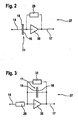
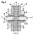
- Two preferred embodiments of the measuring circuit 27 are in the FIGS. 2 and 3 shown, wherein the measuring capacitor 11, a resistor 29 and an inverting operational amplifier 30 in a differentiating arrangement according to Fig. 2 or an integrating arrangement according to Fig. 3 are switched.
- the non-inverting input of the operational amplifier 30 is suitably grounded.
- An additional resistor 31 is provided to prevent, if appropriate, that the output signal is running in the limit.
- the output signal of the measuring circuit 27 corresponding to the outgoing high-frequency wave experiences, due to the interaction with the tobacco 12, a voltage amplitude which is changed with respect to the input amplitude U e U a and a phase shift of ⁇ with respect to the input signal.
- the high-frequency wave passing through the measuring capacitor 11 is conducted via the output line 17 of the measuring circuit 27 to the measured variable determining device 18.
- the measured variable determining device 18 determines suitable measured variables from the high-frequency signal.
- the output of the measuring circuit 27 is supplied to a rectifier 32 and smoothed in a low-pass filter 33.
- the signal thus obtained is proportional to the output amplitude U a .
- the Meß survivenbeticians shark 18 is further supplied to the input signal generated by the Hochfrequenzerzugungs Rhein 13 via the line 34.
- a signal dependent on the generated high-frequency wave is expediently conducted to the circuit device 28 via a line 34, 234 provided in addition to the measuring line via the measuring capacitor 11 in order to be able to use the phase information of the input signal for determining the phase shift of the output signal.
- the input signal of the measuring capacitor 11 via the line 34 and the output of the measuring capacitor 11 and the measuring circuit 27 is passed via a line 35 to the multiplication amplifier 36, multiplied therein and smoothed by a low-pass filter 37.
- the signal thus obtained is proportional to the output amplitude U a times the sine (or cosine) of the phase shift ⁇ .
- any foreign matter 90 contained in the product 12 can be detected when a deviation is detected.
- the measurement signals are conducted via the output lines 19, 20 to the evaluation device 21, in which the evaluation is carried out, for example, by means of a computer program stored therein.
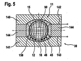
- FIG Fig. 4 A preferred embodiment of a high frequency sensor 38 is shown in FIG Fig. 4 shown.
- the sensor 38 is constructed substantially rotationally symmetrical about the longitudinal axis L. Through a central longitudinal bore 39 of the sensor 38 is in the transport direction T, which coincides with the longitudinal direction L, the Tobacco strand out.
- the sensor comprises two rotationally symmetrical, disc-shaped, oriented perpendicular to the longitudinal direction L main body 40, 41, which are spaced apart by means of an outer, annular, non-conductive limiting body 44 and each having a central through bore 39 for the tobacco rod.
- the measuring capacitor 11 is therefore designed as a plate capacitor with plate-shaped electrodes 15, 16, which are oriented in a circular disk and perpendicular to the longitudinal direction L and have a central passage opening for the tobacco rod 12.
- the field lines are substantially parallel to the transport direction.
- Between the base bodies 40, 41 a field-filled space 45 is formed, which is closed by the limiting body 44 radially outward.
- the high frequency field extends into the central product space 46 and is there with the tobacco 12 in interaction.
- the plates 15, 16 have a smaller radius than the base body 40, 41 in order to prevent leakage of the high-frequency field in the vicinity of the sensor.
- the plates 15, 16 of the plate capacitor 11 may be arranged at a small distance d from each other to improve the measuring resolution in the longitudinal direction L.
- the distance d may in particular be less than the diameter of the tobacco rod 12 and, for example, less than 8 mm, preferably less than 4 mm.
- the base bodies 40, 41 each have a tubular, axially outwardly extending, the tobacco rod comprehensive extension 47, 48.
- the extensions 47, 48 have an inner-walled metallic surface or coating 49, which is expediently connected to the electrodes 15, 16.
- the metallic coating 49 forms a metallic chimney to prevent leakage of the field from the product feedthrough openings of the condenser 11. Furthermore, a tobacco pipe 12 immediately surrounding and this leading, extending over the entire length of the sensor extending tube 50 made of non-conductive material, which prevents contamination of the sensor interior by product residues.
- the field-filled space formed between the electrodes 15, 16 45 to the positive influence of the field profile partially or completely, except for the product space to be filled with a dielectric material.
- the bodies 40, 41, 44 of the sensor 38 are preferably made of a non-conductive material with a very low coefficient of thermal expansion, for example, Zerodur, in order to achieve increased dimensional stability of the sensor 38 against temperature influences. Due to the reduced dependence of the capacitance characteristics of the measuring capacitor 11 on the ambient temperature, an improved measuring accuracy can be achieved.
- a control device not shown, is preferably provided for keeping the sensor temperature constant. It is also conceivable that the base body 40, 41 of the sensor 38 completely or partially made of metal.
- FIG Fig. 5 An embodiment of a sensor 38 not covered by the invention is shown in FIG Fig. 5 shown, wherein corresponding parts are denoted by corresponding reference numerals 100.
- the electrodes 15, 16 are formed by plates, which are arranged parallel to the transport direction oriented perpendicular to the paper plane.
- the field lines run in this example substantially perpendicular to the transport direction.
- the plates 15, 16 are preferably arranged around the product strand 12 and preferably curved to this end.
- FIG Fig. 6 A preferred embodiment of a measuring device 10 is shown in FIG Fig. 6 shown, wherein corresponding parts are denoted by corresponding reference numerals 200th
- the measured variable determining device 18 is implemented digitally electronic.
- the Meß Strukturnbeticians Branson Inc.
- the A / D converter 66 is clocked at a sampling frequency which is higher by a factor n than the frequency of the high frequency wave, where n is a natural number greater than one.
- the measuring device 10 has a means 222 for generating a scanning signal having a sampling frequency, the order a factor n is higher than the frequency of the high frequency wave.
- the sampling signal is passed via line 70 to the A / D converter 66.
- the measured values sampled by means of the A / D converter 66 are passed to the digital processing device 67, which is programmed to determine suitable, independent measured quantities.
- each sampled measured value is multiplied on the one hand with the corresponding value of the sine function and on the other hand with the corresponding value of the cosine function.
- the scanning signal is passed via the line 70 to the processing device 67.
- the sine and cosine values can, for example, be taken from corresponding tabular memories 68, 69.
- the n sine values and n cosine values thus obtained are then summed separately over a period of the high frequency field so that two sums are obtained.
- the high-frequency input signal is passed via the line 234 to the processing device 67, so that it operates in phase with the high-frequency generator 13. From the sums obtained, the two desired measured quantities dependent on the amplitude and the phase of the measurement signal influenced by the product 12 can be unambiguously determined on the basis of specific orthogonality relationships.
- the measurement signals are conducted via the output lines 19, 20 to the evaluation device 21, in which the evaluation is carried out, for example, by means of a computer program stored therein.
- the signal generated by the radio frequency source 222 may also be used to generate the radio frequency wave used for the measurement.
- the signal generated by the high-frequency source 222 by the divider stage 60 is divided by a factor n on a phase-synchronous square wave with the measuring frequency of 5 MHz in the present case and then by means of the PLL circuit 61 in a phase-synchronous sinusoidal signal with the same frequency transformed.
- control device 223, 62-64, 226 for keeping constant the voltage amplitude U e of the output from the amplifier 223 high-frequency wave can digitally electronic be executed.
- the output signal of the amplifier 223 is fed to an A / D converter 62 which is driven via a line 65 with the sampling signal of 50 MHz, whereby n samples of the signal output by the amplifier 223 are generated per period.
- the measured values sampled by the A / D converter 62 are sent to the digital processing device 63.
- each sampled voltage value is multiplied by the corresponding value of the cosine function.
- the scanning signal is passed via the line 65 to the processing device 63.
- the cosine values can, for example, be taken from a corresponding tabular memory 64. The n cosine values obtained in this way are then summed over a period of the high-frequency field.
- the high-frequency input signal is passed via a line 71 to the processing device 63, so that it operates in phase with the high-frequency generator 13.
- the output of the processor 63 is passed to the controller 226, which controls the amplifier 223 in such a way that the output signal of the processing means 63 and thus the amplitude U e of the oscillation at the output of the amplifier 223 has a constant value.
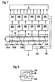
- the embodiment not covered by the invention according to Fig. 7 serves in particular for measurement on a wide, web-shaped product 312, for example a tobacco web, a tow web or a cotton fleece whose width B is substantially greater, for example at least a factor of 3, than its height H.
- a wide, web-shaped product 312 for example a tobacco web, a tow web or a cotton fleece whose width B is substantially greater, for example at least a factor of 3, than its height H.
- Another application relates to the measurement a plurality of juxtaposed product strands, such as tobacco strands.
- the transport direction is perpendicular to the paper plane.
- Corresponding parts are designated by corresponding 300 reference numerals.
- a plurality of measuring capacitors 311A, 311B, ... are used, here for example six, which are arranged across the width of the product.
- the measuring capacitors 311A, 311B, ... are suitably fed by the same high-frequency generator 13.
- all of the input electrodes 315 of the measuring capacitors 311A, 311B, ... are set to the same potential, most simply by shorting the electrodes, as in FIG Fig. 7 shown.
- the measuring circuit 80A, 80B, ... are connected to a measuring circuit 80A, 80B, ..., respectively.
- the measuring circuit 80A, 80B,... Is preferably as in FIG Fig. 8 and, together with the respective measuring capacitor 311A, 311B,..., forms a differential measuring circuit 27 as in FIG Fig. 2 shown.
- the use of a respective inverting operational amplifier 330 connected downstream of the measuring capacitor 311A, 311B,... Is particularly advantageous in this embodiment, since in this way the output electrodes 316A, 316B,... Of all measuring capacitors 311A, 311B,. in particular mass be laid. As a result, the crosstalk between the measuring capacitors 311A, 311B, ... is minimized.
- a measured variable determining device 18A, 18B,... which are in particular digital-electronic, for example as in FIG Fig. 6 shown, can be executed.
- the Meß Strukturnbeticians wornen 18A, 18B, ... are suitably connected to the evaluation device 21 for foreign body detection.
- the corresponding methods for determining the measured variables and for detecting foreign bodies are preferably carried out as described above.
Priority Applications (1)
| Application Number | Priority Date | Filing Date | Title |
|---|---|---|---|
| PL05821673T PL1836484T3 (pl) | 2004-12-22 | 2005-12-17 | Urządzenie pomiarowe i sposób pomiaru do rozpoznawania ciał obcych w tytoniu |
Applications Claiming Priority (2)
| Application Number | Priority Date | Filing Date | Title |
|---|---|---|---|
| DE102004063229A DE102004063229B4 (de) | 2004-12-22 | 2004-12-22 | Meßvorrichtung und -verfahren zur Erkennung von Fremdkörpern in einem Produkt, insbesondere in Tabak, Baumwolle oder einem anderen Faserprodukt |
| PCT/EP2005/013830 WO2006069720A2 (de) | 2004-12-22 | 2005-12-17 | Messvorrichtung und -verfahren zur erkennung von fremdkörpern in einem produkt, insbesondere in tabak, baumwolle oder einem anderen faserprodukt |
Publications (3)
| Publication Number | Publication Date |
|---|---|
| EP1836484A2 EP1836484A2 (de) | 2007-09-26 |
| EP1836484B1 EP1836484B1 (de) | 2013-02-13 |
| EP1836484B9 true EP1836484B9 (de) | 2013-08-14 |
Family
ID=36013320
Family Applications (1)
| Application Number | Title | Priority Date | Filing Date |
|---|---|---|---|
| EP05821673.0A Active EP1836484B9 (de) | 2004-12-22 | 2005-12-17 | Messvorrichtung und -verfahren zur erkennung von fremdkörpern in tabak |
Country Status (7)
| Country | Link |
|---|---|
| US (1) | US7659730B2 (zh) |
| EP (1) | EP1836484B9 (zh) |
| JP (1) | JP4660558B2 (zh) |
| CN (1) | CN101084432B (zh) |
| DE (1) | DE102004063229B4 (zh) |
| PL (1) | PL1836484T3 (zh) |
| WO (1) | WO2006069720A2 (zh) |
Families Citing this family (14)
| Publication number | Priority date | Publication date | Assignee | Title |
|---|---|---|---|---|
| DE102004063228B4 (de) * | 2004-12-22 | 2007-06-28 | Hauni Maschinenbau Ag | Meßvorrichtung und -verfahren zur Bestimmung einer dielektrischen Eigenschaft, insbesondere der Feuchte und/oder Dichte, eines Produkts |
| CH699753A1 (de) * | 2008-10-16 | 2010-04-30 | Uster Technologies Ag | Vorrichtung und verfahren zum ausmessen einer kapazität. |
| CH699752A1 (de) * | 2008-10-16 | 2010-04-30 | Uster Technologies Ag | Vorrichtung und verfahren zum ausmessen einer kapazität. |
| TWI425183B (zh) * | 2010-12-03 | 2014-02-01 | Hon Tech Inc | Immediate inspection of electronic components transfer device |
| DE102011006414C5 (de) | 2011-03-30 | 2021-02-18 | Hauni Maschinenbau Gmbh | Verfahren und Vorrichtung zur Ermittlung von Gewichtsanteilen in einem Filtermaterial |
| DE102011083052B4 (de) | 2011-09-20 | 2016-03-10 | Hauni Maschinenbau Ag | Kapazitive HF-Strangmessvorrichtung und Strangmaschine |
| DE102012102340A1 (de) * | 2012-03-20 | 2013-09-26 | Hauni Maschinenbau Ag | Messanordnung, ausgebildet und eingerichtet zum Messen von in Strangeinheiten der Tabak verarbeitenden Industrie hergestellten Strängen und/oder Strangabschnitten sowie Strangeinheit mit einer solchen Messanordnung |
| DE102012209954A1 (de) * | 2012-06-14 | 2013-12-19 | Hauni Maschinenbau Ag | Verfahren und Vorrichtung zur Erkennung von Stranginhomogenitäten eines Materialstrangs der Tabak verarbeitenden Industrie |
| DE102013217485A1 (de) | 2013-09-03 | 2015-03-05 | Hauni Maschinenbau Ag | Anordnung und Verfahren zur Überprüfung von stabförmigen Artikeln der Tabak verarbeitenden Industrie |
| CN104677955B (zh) * | 2015-01-28 | 2017-09-29 | 华中科技大学 | 一种非金属杂质检测方法 |
| DE102018108601A1 (de) * | 2018-04-11 | 2019-10-17 | saturn petcare gmbh | Vorrichtung zur Erfassung von Fremdkörpern in einem Substratstrom |
| CN110161056B (zh) * | 2019-05-09 | 2023-10-03 | 浙江浙能数字科技有限公司 | 一种输煤系统中输煤皮带上异物的检测装置及方法 |
| EP3811792B1 (en) | 2019-10-21 | 2022-07-06 | International Tobacco Machinery Poland Sp. z o.o. | A feeding apparatus for feeding a tobacco industry segment |
| DE102021126221A1 (de) | 2021-10-08 | 2023-04-13 | Endress+Hauser Flowtec Ag | Verfahren zur Unterscheidung zwischen dem Vorliegen eines Fremdkörpers oder einer Gasblase in einem Medium und entsprechendes System |
Family Cites Families (27)
| Publication number | Priority date | Publication date | Assignee | Title |
|---|---|---|---|---|
| GB717127A (en) | 1951-07-27 | 1954-10-20 | Unilever Ltd | Improvements in apparatus for measuring dielectric properties of materials |
| FR1315918A (fr) | 1961-12-14 | 1963-01-25 | Commissariat Energie Atomique | Détecteur de passages de fragments de gaines |
| GB1132763A (en) | 1966-03-03 | 1968-11-06 | Rowntree And Company Ltd | Measuring moisture content and other properties of solids and liquids |
| US3786349A (en) * | 1973-05-03 | 1974-01-15 | Northern Electric Co | Electrical reactance and loss measurement apparatus and method |
| US3979581A (en) * | 1974-02-26 | 1976-09-07 | Hauni-Werke Korber & Co., Kg | Method and arrangement for determining the mass of tobacco or the like by capacitance and attenuation measurements in a resonant high frequency oscillator circuit |
| DE2500299A1 (de) * | 1974-03-23 | 1975-09-25 | Hauni Werke Koerber & Co Kg | Anordnung zum erfassen der masse eines stromes aus tabak oder einem anderen material der tabakverarbeitenden industrie |
| DE2441832A1 (de) | 1974-08-31 | 1976-03-11 | Hauni Werke Koerber & Co Kg | Verfahren und anordnung zum kapazitiven pruefen der tabakdichte in den enden von stabfoermigen artikeln der tabakverarbeitenden industrie |
| US4114090A (en) * | 1976-08-17 | 1978-09-12 | Imasco Limited | Electronic moisture meter |
| DE2700972C3 (de) * | 1977-01-12 | 1980-06-12 | Truetzschler Gmbh & Co Kg, 4050 Moenchengladbach | Verfahren und Vorrichtung zur Überwachung von Fremdkörpern in einem Textilfaservlies |
| CH657437A5 (de) * | 1982-05-18 | 1986-08-29 | Burckhardt Ag Maschf | Schmiermittel-ueberwachungsanordnung an einem kolbenkompressor. |
| DE3743216C2 (de) | 1987-12-19 | 1996-12-19 | Hauni Werke Koerber & Co Kg | Hochfrequenzschwingkreis |
| DE3825111A1 (de) * | 1988-07-23 | 1990-01-25 | Hauni Werke Koerber & Co Kg | Verfahren und schaltungsanordnung zum bestimmen einer charakteristischen groesse eines hf-oszillators |
| US4947131A (en) * | 1989-04-21 | 1990-08-07 | Modern Controls, Inc. | Capacitance bar sensor |
| US5208544A (en) * | 1990-09-26 | 1993-05-04 | E. I. Du Pont De Nemours And Company | Noninvasive dielectric sensor and technique for measuring polymer properties |
| DE19651355B4 (de) | 1996-12-10 | 2004-03-18 | Fresenius Medical Care Deutschland Gmbh | Gasblasendetektor |
| US5792938A (en) * | 1996-12-13 | 1998-08-11 | Panametrics, Inc. | Humidity sensor with differential thermal detection and method of sensing |
| EP0902277A1 (de) | 1997-08-13 | 1999-03-17 | Hauni Maschinenbau Aktiengesellschaft | Verfahren und Anordnung zum Erfassen mindestens einer Eigenschaft eines Stoffes |
| DE59814414D1 (de) * | 1997-12-18 | 2010-01-07 | Uster Technologies Ag | Verfahren und Vorrichtung zur Ermittlung von Anteilen fester Stoffe in einem Prüfgut |
| US6076480A (en) * | 1999-02-11 | 2000-06-20 | The United States Of America As Represented By The Secretary Of The Navy | Fuel storing water ballast tank internally structured for reducing retention of water and overboard discharge of fuel |
| JP2001320253A (ja) * | 2000-05-12 | 2001-11-16 | Nec Miyagi Ltd | 前置増幅回路 |
| CN100425989C (zh) * | 2000-05-31 | 2008-10-15 | 乌斯特技术股份公司 | 识别在纵向移动的纱线状产品中的杂质的方法及装置 |
| DE10037180C1 (de) * | 2000-07-31 | 2002-01-17 | Reemtsma H F & Ph | Verfahren zum Detektieren und Selektieren von Fremdkörpern in Cigaretten |
| DE10100664A1 (de) * | 2001-01-09 | 2002-07-11 | Hauni Maschinenbau Ag | Verfahren zum Prüfen eines Produktionsmaterials |
| US6885199B2 (en) * | 2001-05-17 | 2005-04-26 | Siemens Vdo Automotive Corp. | Fuel sensor |
| EP1327876B1 (de) * | 2002-01-11 | 2003-12-17 | TEWS ELEKTRONIK Dipl.-Ing. Manfred Tews | Verfahren und Vorrichtung zur Erkennung von Fremdkörpern in Masseströmen mit Hilfe eines Mikrowellen-Resonators |
| ITBO20020038A1 (it) * | 2002-01-24 | 2003-07-24 | Gd Spa | Metodo per il rilevamento e l'eliminazione di corpi estranei in un flusso di tabacco |
| DE102004063228B4 (de) * | 2004-12-22 | 2007-06-28 | Hauni Maschinenbau Ag | Meßvorrichtung und -verfahren zur Bestimmung einer dielektrischen Eigenschaft, insbesondere der Feuchte und/oder Dichte, eines Produkts |
-
2004
- 2004-12-22 DE DE102004063229A patent/DE102004063229B4/de not_active Expired - Fee Related
-
2005
- 2005-12-17 CN CN2005800441412A patent/CN101084432B/zh active Active
- 2005-12-17 WO PCT/EP2005/013830 patent/WO2006069720A2/de active Application Filing
- 2005-12-17 PL PL05821673T patent/PL1836484T3/pl unknown
- 2005-12-17 US US11/793,948 patent/US7659730B2/en active Active
- 2005-12-17 EP EP05821673.0A patent/EP1836484B9/de active Active
- 2005-12-17 JP JP2007547351A patent/JP4660558B2/ja active Active
Also Published As
| Publication number | Publication date |
|---|---|
| US20080084220A1 (en) | 2008-04-10 |
| JP2008524613A (ja) | 2008-07-10 |
| EP1836484B1 (de) | 2013-02-13 |
| DE102004063229A1 (de) | 2006-07-13 |
| US7659730B2 (en) | 2010-02-09 |
| PL1836484T3 (pl) | 2013-07-31 |
| JP4660558B2 (ja) | 2011-03-30 |
| CN101084432A (zh) | 2007-12-05 |
| WO2006069720A2 (de) | 2006-07-06 |
| WO2006069720A3 (de) | 2006-08-10 |
| EP1836484A2 (de) | 2007-09-26 |
| DE102004063229B4 (de) | 2007-06-14 |
| CN101084432B (zh) | 2012-03-21 |
Similar Documents
| Publication | Publication Date | Title |
|---|---|---|
| EP1836484B9 (de) | Messvorrichtung und -verfahren zur erkennung von fremdkörpern in tabak | |
| WO2006069721A2 (de) | Messvorrichtung und -verfahren zur bestimmung einer dielektrischen eigenschaft, insbesondere der feuchte und/oder dichte, eines produkts | |
| DE19705260B4 (de) | Anordnung zum Erfassen mindestens einer dielektrischen Eigenschaft eines Stoffes | |
| DE19610844C2 (de) | Verfahren und System zum Messen von physikalischen Parametern eines Werkstückes | |
| DE19650112C1 (de) | Einrichtung und Verfahren zum Messen eines Pulver-Massestromes | |
| EP2121203B1 (de) | Verfahren und vorrichtung zum unterscheiden von ein elektromagnetisches wechselfeld beeinflussenden objekten, insbesondere metallobjekten | |
| DE4406046C2 (de) | Einrichtung und Verfahren zum Messen eines Pulver-Massestromes | |
| DE69631691T2 (de) | Spielmesssystem | |
| DE19906442C2 (de) | Verfahren zum Messen des Abstandes zwischen einer Sensorelektrode und einem Werkstück | |
| EP0753755A2 (de) | Vorrichtung zur Messung der komplexen Dielektrizitätskonstanten von Tabak | |
| WO2005100924A1 (de) | Vorrichtung, sensoranordnung und verfahren zur kapazitiven positionserfassung eines zielobjekts | |
| DE19651355B4 (de) | Gasblasendetektor | |
| EP2347250A1 (de) | Vorrichtung und verfahren zur bestimmung einer dielektrischen eigenschaft einer kondensatoranordnung | |
| EP1219933B1 (de) | Differential-Wirbelstromgeber | |
| DE19734978A1 (de) | Verfahren und Anordnung zum Erfassen mindestens einer Eigenschaft eines Stoffes | |
| EP2567263B1 (de) | Erfassung eines metallischen oder magnetischen objekts | |
| DE19755417A1 (de) | Auswerteschaltung zur Ermittlung komplexer Impedanzen, Vorrichtung zur Messung komplexer Impedanzen und Verwendung der Vorrichtung | |
| DE3401140C1 (de) | Vorrichtung zur kontinuierlichen Messung der Dicke | |
| EP3824323B1 (de) | Detektor zum detektieren von elektrisch leitfähigem material | |
| DE102017128472A1 (de) | Induktiver Näherungsschalter und Verfahren zum Betreiben eines induktiven Näherungsschalters | |
| WO2021223987A1 (de) | Magnetisch-induktive Durchflussmessvorrichtung und Verfahren zum Ermitteln eines Füllstandes | |
| DE2507398C3 (de) | Schaltungsanordnung zum Prüfen metallischer Gegenstände | |
| EP0943913A2 (de) | Verfahren und Einrichtung zum Bestimmen der Zusammensetzung von fluidisierbaren Feststoffpartikeln | |
| WO2010136152A1 (de) | Messanordnung zum erfassen eines volumenstromes und messverfahren | |
| DD284531A5 (de) | Verfahren und anordnung zum bestimmen von verunreinigungen und stoerstellen in fasermaterialien |
Legal Events
| Date | Code | Title | Description |
|---|---|---|---|
| PUAI | Public reference made under article 153(3) epc to a published international application that has entered the european phase |
Free format text: ORIGINAL CODE: 0009012 |
|
| 17P | Request for examination filed |
Effective date: 20070720 |
|
| AK | Designated contracting states |
Kind code of ref document: A2 Designated state(s): AT BE BG CH CY CZ DE DK EE ES FI FR GB GR HU IE IS IT LI LT LU LV MC NL PL PT RO SE SI SK TR |
|
| RAP1 | Party data changed (applicant data changed or rights of an application transferred) |
Owner name: HAUNI MASCHINENBAU AG |
|
| 17Q | First examination report despatched |
Effective date: 20080128 |
|
| DAX | Request for extension of the european patent (deleted) | ||
| GRAP | Despatch of communication of intention to grant a patent |
Free format text: ORIGINAL CODE: EPIDOSNIGR1 |
|
| RTI1 | Title (correction) |
Free format text: MEASURING DEVICE AND METHOD FOR RECOGNIZING FOREIGN BODIES IN TOBACCO |
|
| GRAS | Grant fee paid |
Free format text: ORIGINAL CODE: EPIDOSNIGR3 |
|
| GRAA | (expected) grant |
Free format text: ORIGINAL CODE: 0009210 |
|
| AK | Designated contracting states |
Kind code of ref document: B1 Designated state(s): AT BE BG CH CY CZ DE DK EE ES FI FR GB GR HU IE IS IT LI LT LU LV MC NL PL PT RO SE SI SK TR |
|
| REG | Reference to a national code |
Ref country code: GB Ref legal event code: FG4D Free format text: NOT ENGLISH Ref country code: DE Ref legal event code: R081 Ref document number: 502005013469 Country of ref document: DE Owner name: HAUNI MASCHINENBAU GMBH, DE Free format text: FORMER OWNER: HAUNI MASCHINENBAU AG, 21033 HAMBURG, DE |
|
| REG | Reference to a national code |
Ref country code: AT Ref legal event code: REF Ref document number: 596742 Country of ref document: AT Kind code of ref document: T Effective date: 20130215 |
|
| REG | Reference to a national code |
Ref country code: IE Ref legal event code: FG4D Free format text: LANGUAGE OF EP DOCUMENT: GERMAN |
|
| REG | Reference to a national code |
Ref country code: DE Ref legal event code: R096 Ref document number: 502005013469 Country of ref document: DE Effective date: 20130411 |
|
| REG | Reference to a national code |
Ref country code: NL Ref legal event code: T3 |
|
| REG | Reference to a national code |
Ref country code: LT Ref legal event code: MG4D |
|
| PG25 | Lapsed in a contracting state [announced via postgrant information from national office to epo] |
Ref country code: LT Free format text: LAPSE BECAUSE OF FAILURE TO SUBMIT A TRANSLATION OF THE DESCRIPTION OR TO PAY THE FEE WITHIN THE PRESCRIBED TIME-LIMIT Effective date: 20130213 Ref country code: CY Free format text: LAPSE BECAUSE OF FAILURE TO SUBMIT A TRANSLATION OF THE DESCRIPTION OR TO PAY THE FEE WITHIN THE PRESCRIBED TIME-LIMIT Effective date: 20130213 Ref country code: SE Free format text: LAPSE BECAUSE OF FAILURE TO SUBMIT A TRANSLATION OF THE DESCRIPTION OR TO PAY THE FEE WITHIN THE PRESCRIBED TIME-LIMIT Effective date: 20130213 Ref country code: IS Free format text: LAPSE BECAUSE OF FAILURE TO SUBMIT A TRANSLATION OF THE DESCRIPTION OR TO PAY THE FEE WITHIN THE PRESCRIBED TIME-LIMIT Effective date: 20130613 Ref country code: ES Free format text: LAPSE BECAUSE OF FAILURE TO SUBMIT A TRANSLATION OF THE DESCRIPTION OR TO PAY THE FEE WITHIN THE PRESCRIBED TIME-LIMIT Effective date: 20130524 Ref country code: BG Free format text: LAPSE BECAUSE OF FAILURE TO SUBMIT A TRANSLATION OF THE DESCRIPTION OR TO PAY THE FEE WITHIN THE PRESCRIBED TIME-LIMIT Effective date: 20130513 |
|
| REG | Reference to a national code |
Ref country code: PL Ref legal event code: T3 |
|
| PG25 | Lapsed in a contracting state [announced via postgrant information from national office to epo] |
Ref country code: PT Free format text: LAPSE BECAUSE OF FAILURE TO SUBMIT A TRANSLATION OF THE DESCRIPTION OR TO PAY THE FEE WITHIN THE PRESCRIBED TIME-LIMIT Effective date: 20130613 Ref country code: GR Free format text: LAPSE BECAUSE OF FAILURE TO SUBMIT A TRANSLATION OF THE DESCRIPTION OR TO PAY THE FEE WITHIN THE PRESCRIBED TIME-LIMIT Effective date: 20130514 Ref country code: LV Free format text: LAPSE BECAUSE OF FAILURE TO SUBMIT A TRANSLATION OF THE DESCRIPTION OR TO PAY THE FEE WITHIN THE PRESCRIBED TIME-LIMIT Effective date: 20130213 Ref country code: SI Free format text: LAPSE BECAUSE OF FAILURE TO SUBMIT A TRANSLATION OF THE DESCRIPTION OR TO PAY THE FEE WITHIN THE PRESCRIBED TIME-LIMIT Effective date: 20130213 Ref country code: FI Free format text: LAPSE BECAUSE OF FAILURE TO SUBMIT A TRANSLATION OF THE DESCRIPTION OR TO PAY THE FEE WITHIN THE PRESCRIBED TIME-LIMIT Effective date: 20130213 |
|
| PG25 | Lapsed in a contracting state [announced via postgrant information from national office to epo] |
Ref country code: SK Free format text: LAPSE BECAUSE OF FAILURE TO SUBMIT A TRANSLATION OF THE DESCRIPTION OR TO PAY THE FEE WITHIN THE PRESCRIBED TIME-LIMIT Effective date: 20130213 Ref country code: DK Free format text: LAPSE BECAUSE OF FAILURE TO SUBMIT A TRANSLATION OF THE DESCRIPTION OR TO PAY THE FEE WITHIN THE PRESCRIBED TIME-LIMIT Effective date: 20130213 Ref country code: RO Free format text: LAPSE BECAUSE OF FAILURE TO SUBMIT A TRANSLATION OF THE DESCRIPTION OR TO PAY THE FEE WITHIN THE PRESCRIBED TIME-LIMIT Effective date: 20130213 Ref country code: EE Free format text: LAPSE BECAUSE OF FAILURE TO SUBMIT A TRANSLATION OF THE DESCRIPTION OR TO PAY THE FEE WITHIN THE PRESCRIBED TIME-LIMIT Effective date: 20130213 Ref country code: CZ Free format text: LAPSE BECAUSE OF FAILURE TO SUBMIT A TRANSLATION OF THE DESCRIPTION OR TO PAY THE FEE WITHIN THE PRESCRIBED TIME-LIMIT Effective date: 20130213 |
|
| PLBE | No opposition filed within time limit |
Free format text: ORIGINAL CODE: 0009261 |
|
| STAA | Information on the status of an ep patent application or granted ep patent |
Free format text: STATUS: NO OPPOSITION FILED WITHIN TIME LIMIT |
|
| 26N | No opposition filed |
Effective date: 20131114 |
|
| REG | Reference to a national code |
Ref country code: DE Ref legal event code: R097 Ref document number: 502005013469 Country of ref document: DE Effective date: 20131114 |
|
| BERE | Be: lapsed |
Owner name: HAUNI MASCHINENBAU A.G. Effective date: 20131231 |
|
| REG | Reference to a national code |
Ref country code: CH Ref legal event code: PL |
|
| GBPC | Gb: european patent ceased through non-payment of renewal fee |
Effective date: 20131217 |
|
| PG25 | Lapsed in a contracting state [announced via postgrant information from national office to epo] |
Ref country code: LU Free format text: LAPSE BECAUSE OF FAILURE TO SUBMIT A TRANSLATION OF THE DESCRIPTION OR TO PAY THE FEE WITHIN THE PRESCRIBED TIME-LIMIT Effective date: 20131217 Ref country code: MC Free format text: LAPSE BECAUSE OF FAILURE TO SUBMIT A TRANSLATION OF THE DESCRIPTION OR TO PAY THE FEE WITHIN THE PRESCRIBED TIME-LIMIT Effective date: 20130213 |
|
| REG | Reference to a national code |
Ref country code: IE Ref legal event code: MM4A |
|
| REG | Reference to a national code |
Ref country code: FR Ref legal event code: ST Effective date: 20140829 |
|
| PG25 | Lapsed in a contracting state [announced via postgrant information from national office to epo] |
Ref country code: CH Free format text: LAPSE BECAUSE OF NON-PAYMENT OF DUE FEES Effective date: 20131231 Ref country code: LI Free format text: LAPSE BECAUSE OF NON-PAYMENT OF DUE FEES Effective date: 20131231 Ref country code: IE Free format text: LAPSE BECAUSE OF NON-PAYMENT OF DUE FEES Effective date: 20131217 Ref country code: BE Free format text: LAPSE BECAUSE OF NON-PAYMENT OF DUE FEES Effective date: 20131231 |
|
| PG25 | Lapsed in a contracting state [announced via postgrant information from national office to epo] |
Ref country code: GB Free format text: LAPSE BECAUSE OF NON-PAYMENT OF DUE FEES Effective date: 20131217 Ref country code: FR Free format text: LAPSE BECAUSE OF NON-PAYMENT OF DUE FEES Effective date: 20131231 |
|
| REG | Reference to a national code |
Ref country code: AT Ref legal event code: MM01 Ref document number: 596742 Country of ref document: AT Kind code of ref document: T Effective date: 20131217 |
|
| PG25 | Lapsed in a contracting state [announced via postgrant information from national office to epo] |
Ref country code: AT Free format text: LAPSE BECAUSE OF NON-PAYMENT OF DUE FEES Effective date: 20131217 |
|
| PG25 | Lapsed in a contracting state [announced via postgrant information from national office to epo] |
Ref country code: TR Free format text: LAPSE BECAUSE OF FAILURE TO SUBMIT A TRANSLATION OF THE DESCRIPTION OR TO PAY THE FEE WITHIN THE PRESCRIBED TIME-LIMIT Effective date: 20130213 |
|
| PG25 | Lapsed in a contracting state [announced via postgrant information from national office to epo] |
Ref country code: HU Free format text: LAPSE BECAUSE OF FAILURE TO SUBMIT A TRANSLATION OF THE DESCRIPTION OR TO PAY THE FEE WITHIN THE PRESCRIBED TIME-LIMIT; INVALID AB INITIO Effective date: 20051217 |
|
| REG | Reference to a national code |
Ref country code: DE Ref legal event code: R081 Ref document number: 502005013469 Country of ref document: DE Owner name: HAUNI MASCHINENBAU GMBH, DE Free format text: FORMER OWNER: HAUNI MASCHINENBAU AG, 21033 HAMBURG, DE |
|
| REG | Reference to a national code |
Ref country code: NL Ref legal event code: PD Owner name: HAUNI MASCHINENBAU GMBH; DE Free format text: DETAILS ASSIGNMENT: VERANDERING VAN EIGENAAR(S), VERANDERING VAN DE JURIDISCHE ENTITEIT; FORMER OWNER NAME: HAUNI MASCHINENBAU AG Effective date: 20160928 |
|
| REG | Reference to a national code |
Ref country code: DE Ref legal event code: R081 Ref document number: 502005013469 Country of ref document: DE Owner name: KOERBER TECHNOLOGIES GMBH, DE Free format text: FORMER OWNER: HAUNI MASCHINENBAU GMBH, 21033 HAMBURG, DE |
|
| REG | Reference to a national code |
Ref country code: NL Ref legal event code: HC Owner name: KOERBER TECHNOLOGIES GMBH; DE Free format text: DETAILS ASSIGNMENT: CHANGE OF OWNER(S), CHANGE OF OWNER(S) NAME; FORMER OWNER NAME: HAUNI MASCHINENBAU GMBH Effective date: 20221020 |
|
| P01 | Opt-out of the competence of the unified patent court (upc) registered |
Effective date: 20230608 |
|
| PGFP | Annual fee paid to national office [announced via postgrant information from national office to epo] |
Ref country code: NL Payment date: 20231220 Year of fee payment: 19 Ref country code: IT Payment date: 20231227 Year of fee payment: 19 |
|
| PGFP | Annual fee paid to national office [announced via postgrant information from national office to epo] |
Ref country code: PL Payment date: 20231128 Year of fee payment: 19 |
|
| PGFP | Annual fee paid to national office [announced via postgrant information from national office to epo] |
Ref country code: DE Payment date: 20231221 Year of fee payment: 19 |