EP1836469B1 - Luftblaseinrichtung zur kühlung des verbrennungsmotors eines auf einer walzenbühne geprüften fahrzeugs - Google Patents
Luftblaseinrichtung zur kühlung des verbrennungsmotors eines auf einer walzenbühne geprüften fahrzeugs Download PDFInfo
- Publication number
- EP1836469B1 EP1836469B1 EP05825166A EP05825166A EP1836469B1 EP 1836469 B1 EP1836469 B1 EP 1836469B1 EP 05825166 A EP05825166 A EP 05825166A EP 05825166 A EP05825166 A EP 05825166A EP 1836469 B1 EP1836469 B1 EP 1836469B1
- Authority
- EP
- European Patent Office
- Prior art keywords
- vehicle
- nozzle
- air
- air blower
- opening
- Prior art date
- Legal status (The legal status is an assumption and is not a legal conclusion. Google has not performed a legal analysis and makes no representation as to the accuracy of the status listed.)
- Expired - Lifetime
Links
Images

Classifications
-
- G—PHYSICS
- G01—MEASURING; TESTING
- G01M—TESTING STATIC OR DYNAMIC BALANCE OF MACHINES OR STRUCTURES; TESTING OF STRUCTURES OR APPARATUS, NOT OTHERWISE PROVIDED FOR
- G01M17/00—Testing of vehicles
- G01M17/007—Wheeled or endless-tracked vehicles
- G01M17/0072—Wheeled or endless-tracked vehicles the wheels of the vehicle co-operating with rotatable rolls
- G01M17/0074—Details, e.g. roller construction, vehicle restraining devices
Definitions
- the present invention relates to an air blower device for cooling the internal combustion engine of a motor vehicle tested on a chassis dynamometer.
- Known blowing devices comprise an air blower adapted to blow air to the inlet opening provided at the front of the vehicle to direct the flow of air to the engine radiator.
- the fan should create the same air flow as the air entering the intake air opening at the front of the vehicle when it is traveling at the speeds allowed on the road.
- An object of the present invention is to overcome this disadvantage.
- the present invention makes it possible to concentrate the flow of air produced by the fan towards the air intake opening provided on the vehicle tested on the chassis dynamometer, so that this air inlet opening receives a flow comparable to the air it receives when the vehicle is traveling on the road.
- Another object of the present invention is to overcome this disadvantage.
- the device for blowing air to cool the internal combustion engine of a motor vehicle tested on a roller dynamometer comprising an air blower adapted to blow the air towards the air intake opening provided on the vehicle to direct the flow of air towards the cooling members of the engine, comprising a nozzle placed between the outlet opening of the air blower and said opening provided on the vehicle, said nozzle having a cross-section relative to the air flow which progressively decreases between said blower outlet opening and said inlet opening of the vehicle, characterized in that said nozzle comprises two side walls each having an opening for the passage of a strap whose one end is intended to be fixed to the vehicle and the other end is intended to be fixed to a wall Fixed vertical placed near the fan outlet.
- the two straps when the two straps are fixed, they converge to a point of attachment of the vehicle, each entering into one of the lateral openings of the nozzle and out of it by its output.
- This attachment point of the vehicle may be its tow hook.
- each of the lateral openings of the nozzle is constituted by a series of vertical and parallel slots, each of these slots having a width adapted to the passage of one of the two straps.
- This arrangement allows to change the passage of the straps, depending on the vehicle that is tested, particularly depending on the location of its tow hook that varies from one vehicle to another.
- the slots other than that serving as a passage for one of the straps are closed by removable plates.
- This arrangement avoids any loss of air flow through the slots not used for the passage of a strap.
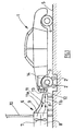
- the figure 1 represents a motor vehicle 1 in position on a test bench with rollers 2.
- the two front wheels 3 of the vehicle 1 rest on the two rollers 2 and drive them in rotation.
- the rear wheels 4 of the vehicle 1 rest on the ground 5.
- an air blower device 6 In front of the vehicle 1 is installed an air blower device 6.
- This device comprises a fan 7 driven in rotation along a horizontal axis in a duct 8 whose outlet opening 9 opens onto the face of a wall 10 adjacent to the vehicle 1.
- a nozzle 11 is placed between the outlet opening 9 of the duct 8 of the fan 7 and the opening 12 provided at the front of the vehicle 1 which makes it possible to direct the flow of air F towards the radiator 13 engine cooling 14.
- the section of the nozzle 11 transverse to the air flow F decreases progressively between the outlet opening 9 of the duct 8 of the fan 7 and the air inlet opening 12 of the vehicle 1.
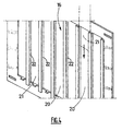
- the nozzle 11 has two lateral walls 15 each having an opening 16 for the passage of a strap 17 whose one end is fixed (see figure 2 ) to the vehicle and the other end is fixed to the vertical wall 10 of which opens the outlet 9 of the duct of the fan 7.
- each strap 17 enters a lateral opening 16 of the nozzle 11 and leaves it from its outlet 19.
- Each lateral opening 16 is formed by a grid having a series of vertical and parallel slots 20 having a width adapted to the passage of one of the two straps 17.
- the slots 20 other than that serving for the passage of a strap 17 may be closed by removable plates, such as the wafer 21 shown in dashed lines on the figure 4 .
- the slots 20 comprise on each side, a slide 22 allowing a sliding attachment of a wafer 21.
- the slots 20 provided on the lateral openings 16 of the nozzle 11 to adjust the spatial position of the straps 17 according to the characteristics of the vehicle 1 and in particular the position of its tow hook 18.
- the blast nozzle 11 may be suitable for a wide variety of vehicles.
- the plates 21 which close the slots 20 not used for the straps allow to limit leakage of the air flow to the sides of the nozzle 11.
- the inlet of the nozzle 11 is connected in a substantially watertight manner (see FIG. figure 2 ) at the outlet 9 of the blower duct 7.
- the outlet 19 of the nozzle 11 is disposed as close as possible to the air inlet opening 12 of the vehicle 1.
- the ideal would also be that the section of the outlet 19 of the nozzle 11 corresponds to that of the air inlet opening 12 of the vehicle 1.
- the nozzle 11 is designed so that the section of its outlet 19 corresponds to the average of the section of the inlet openings 12 provided on this set of vehicles.
- the cross section of the nozzle 11 is rectangular.
- its upper wall 11a is rounded and its bottom wall 11b is flat and extends substantially parallel to the ground 5.
- the rounded shape of the upper wall 11a minimizes turbulence.
- the blowing device that has just been described makes it possible to create a flow of air presenting at the outlet of the nozzle 11 a speed of up to 130 km / h comparable to the flow of air entering the front opening 12 of the vehicle. traveling on the road at the speed of 130 km / h above.
- the invention thus makes it possible to put the tested vehicles on a chassis dynamometer under the same cooling conditions as those encountered on the road.
Landscapes
- Physics & Mathematics (AREA)
- General Physics & Mathematics (AREA)
- Testing Of Engines (AREA)
- Aerodynamic Tests, Hydrodynamic Tests, Wind Tunnels, And Water Tanks (AREA)
- Structures Of Non-Positive Displacement Pumps (AREA)
- Cooling, Air Intake And Gas Exhaust, And Fuel Tank Arrangements In Propulsion Units (AREA)
Claims (9)
- Lufteinblasvorrichtung zum Kühlen der Brennkraftmaschine (14) eines auf einem Rollenstand (2) getesteten Kraftfahrzeugs (1), mit einem Lufteinblasgebläse (7), das ausgelegt ist, um Luft in die Lufteinlassöffnung (12), die in dem Fahrzeug vorgesehen ist (1), einzublasen, um den Luftstrom (F) zu den Kühlelementen der Maschine zu lenken, und mit einer Düse (11), die zwischen der Auslassöffnung (9) des Lufteinblasgebläses (7) und der in dem Fahrzeug (1) vorgesehenen Öffnung (12) angeordnet ist, wobei diese Düse (11) einen Querschnitt in Bezug auf den Luftstrom (F) besitzt, der zwischen der Auslassöffnung (9) des Gebläses (7) und der Einlassöffnung (12) des Fahrzeugs progressiv abnimmt, dadurch gekennzeichnet, dass die Düse (11) zwei Seitenwände (15) aufweist, die jeweils eine Öffnung (16) besitzen, die den Durchgang eines Bandes (17) ermöglichen, wovon ein Ende dazu bestimmt ist, am Fahrzeug (1) befestigt zu werden, und das andere Ende dazu bestimmt ist, an einer festen vertikalen Wand (10) befestigt zu werden, die in der Nähe des Auslasses (9) des Gebläses (7) angeordnet ist.
- Lufteinblasvorrichtung nach Anspruch 1, dadurch gekennzeichnet, dass die beiden Bänder (17) dann, wenn sie befestigt sind, zu einem Befestigungspunkt (18) des Fahrzeugs zusammenlaufen, indem sie jeweils in eine der seitlichen Öffnungen (16) der Düse (11) eintreten und hiervon durch deren Auslass (19) austreten.
- Einblasvorrichtung nach Anspruch 2, dadurch gekennzeichnet, dass der Befestigungspunkt (18) des Fahrzeugs der Abschlepphaken ist.
- Lufteinblasvorrichtung nach einem der Ansprüche 1 bis 3, dadurch gekennzeichnet, dass jede der seitlichen Öffnungen (16) der Düse (11) durch eine Reihe von vertikalen und parallelen Schlitzen (20) gebildet ist, wobei jeder dieser Schlitze (20) eine an den Durchgang eines der zwei Bänder (17) angepasste Breite besitzt.
- Lufteinblasvorrichtung nach Anspruch 4, dadurch gekennzeichnet, dass die Schlitze (20) mit Ausnahme jener, die für den Durchgang eines der Bänder (17) dienen, durch abnehmbare Platten (21) verschlossen sind.
- Lufteinblasvorrichtung nach einem der Ansprüche 1 bis 5, dadurch gekennzeichnet, dass der Einlass der Düse (11) auf im Wesentlichen dichte Weise mit dem Auslass (9) des Einblasgebläses (7) verbunden ist.
- Lufteinblasvorrichtung nach einem der Ansprüche 1 bis 6, dadurch gekennzeichnet, dass die Querschnittsfläche des Auslasses (19) der Düse (11) im Wesentlichen der durchschnittlichen Querschnittsfläche der Einlassöffnungen (12) entspricht, die in allen Großserienfahrzeugen vorgesehen sind.
- Luftblasvorrichtung nach einem der Ansprüche 1 bis 7, dadurch gekennzeichnet, dass die Querschnittsfläche der Düse (11) im Wesentlichen rechtwinklig ist.
- Luftblasvorrichtung nach Anspruch 8, dadurch gekennzeichnet, dass die obere Wand (11a) der Düse (11) abgerundet ist und dass die untere Wand (11b) eben ist und sich im Wesentlichen parallel zum Boden (5) erstreckt.
Applications Claiming Priority (2)
| Application Number | Priority Date | Filing Date | Title |
|---|---|---|---|
| FR0413411A FR2879742B1 (fr) | 2004-12-16 | 2004-12-16 | Dispositif de soufflage d'air pour refroidir le moteur a combustion interne d'un vehicule teste sur banc a rouleaux |
| PCT/FR2005/051086 WO2006064162A1 (fr) | 2004-12-16 | 2005-12-14 | Dispositif de soufflage d'air pour refroidir le moteur a combustion interne d'un vehicule teste sur banc a rouleaux |
Publications (2)
| Publication Number | Publication Date |
|---|---|
| EP1836469A1 EP1836469A1 (de) | 2007-09-26 |
| EP1836469B1 true EP1836469B1 (de) | 2008-05-28 |
Family
ID=34951586
Family Applications (1)
| Application Number | Title | Priority Date | Filing Date |
|---|---|---|---|
| EP05825166A Expired - Lifetime EP1836469B1 (de) | 2004-12-16 | 2005-12-14 | Luftblaseinrichtung zur kühlung des verbrennungsmotors eines auf einer walzenbühne geprüften fahrzeugs |
Country Status (8)
| Country | Link |
|---|---|
| US (1) | US7946812B2 (de) |
| EP (1) | EP1836469B1 (de) |
| JP (1) | JP4772059B2 (de) |
| AT (1) | ATE397203T1 (de) |
| DE (1) | DE602005007268D1 (de) |
| ES (1) | ES2306280T3 (de) |
| FR (1) | FR2879742B1 (de) |
| WO (1) | WO2006064162A1 (de) |
Families Citing this family (9)
| Publication number | Priority date | Publication date | Assignee | Title |
|---|---|---|---|---|
| FR2930338B1 (fr) * | 2008-04-16 | 2011-08-19 | Renault Sas | Dispositif et procede de test pour vehicule automobile. |
| DE102009022675A1 (de) * | 2009-05-26 | 2010-12-16 | Horiba Europe Gmbh | Prüfstand mit temperaturgesteuertem Kühlgebläse |
| FI125885B (fi) * | 2013-02-12 | 2016-03-31 | Jptuf Oy | Menetelmä palamisilman järjestämiseksi lämpimässä sisätilassa olevalle polttomoottorille |
| DE102014111585A1 (de) * | 2014-08-13 | 2016-02-18 | Horiba Europe Gmbh | Prüfstand mit einer Kühlgaszuströmvorrichtung |
| EP3293504B1 (de) * | 2016-09-13 | 2019-04-03 | IVD Prof. Hohenberg GmbH | Verfahren zur regelung oder steuerung der thermischen bedingungen an einem prüfstand |
| AT15462U1 (de) * | 2016-09-13 | 2017-09-15 | Ivd Prof Hohenberg Gmbh | Verfahren und einrichtung zur regelung oder steuerung der thermischen bedingungen an einem prüfstand |
| DE102017131272A1 (de) | 2017-12-22 | 2019-06-27 | AVL Zöllner GmbH | Fahrzeugfesselung für ein zu prüfendes Fahrzeug |
| JP7108443B2 (ja) * | 2018-03-30 | 2022-07-28 | 株式会社マキタ | 送風作業機 |
| JP6687148B1 (ja) * | 2019-05-21 | 2020-04-22 | 株式会社明電舎 | シャシダイナモメータの送風ダクト |
Family Cites Families (37)
| Publication number | Priority date | Publication date | Assignee | Title |
|---|---|---|---|---|
| US3057192A (en) * | 1959-09-21 | 1962-10-09 | Union Oil Co | Chassis dynamometer |
| US3837581A (en) * | 1973-10-11 | 1974-09-24 | Continental Hair Prod | Hair dryer nozzles |
| US3926043A (en) * | 1974-04-24 | 1975-12-16 | Lab Equipment Corp | Road simulator system with provision for engine degradation compensation |
| US3940978A (en) * | 1974-09-13 | 1976-03-02 | James William Akkerman | Motorcycle dynamometer |
| JPS5837491B2 (ja) * | 1976-08-30 | 1983-08-16 | クレイトン マニユフアクチユアリング カンパニ− | 慣性および道路負荷シミュレ−タ |
| JPS56151949A (en) * | 1980-04-26 | 1981-11-25 | Canon Inc | Copying apparatus |
| JPS582633A (ja) * | 1981-06-26 | 1983-01-08 | Mitsubishi Electric Corp | シヤ−シダイナモメ−タ |
| JPS5847149A (ja) * | 1981-09-16 | 1983-03-18 | Nippon Soken Inc | 排気ガス再循環装置 |
| USD282396S (en) * | 1982-12-06 | 1986-01-28 | Lloyd's Carpet & Furniture Cleaning, Inc. | Carpet dryer |
| JPS6136547A (ja) * | 1984-07-27 | 1986-02-21 | Toyota Motor Corp | 自動変速機の油圧制御装置 |
| US4964298A (en) * | 1987-03-02 | 1990-10-23 | Kabushiki-Kaisha Toyo Seisakusho | Device for controlling the air pressure in the low pressure environmental testing chamber for self-propelled vehicles |
| US4799390A (en) * | 1987-03-11 | 1989-01-24 | Kabushiki-Kaisha Toyo Seisakusho | Snow-weathering test apparatus for self-propelled vehicle |
| DE3715016C1 (en) * | 1987-05-06 | 1988-12-01 | Daimler Benz Ag | Noise test stand for motor vehicles |
| JPH0395946A (ja) * | 1989-09-07 | 1991-04-22 | Fujitsu Ltd | 半導体チップのボンデング構造 |
| US5010763A (en) * | 1990-01-24 | 1991-04-30 | Schneider William J | Road simulation device |
| US5148512A (en) * | 1990-08-03 | 1992-09-15 | Owens James L | Hair dryer with air delivery shroud providing small exhaust openings having metallic heat transfer means |
| US5157757A (en) * | 1991-05-14 | 1992-10-20 | China Pacific Trade Ltd. | Hand held hair dryer with selectively positionable baffle for varying the distribution of air from the dryer |
| US5526675A (en) * | 1993-04-26 | 1996-06-18 | Power-Tek, Inc. | Method and apparatus for measuring evaporative emissions in a fixed-volume enclosure |
| US5533388A (en) * | 1994-02-23 | 1996-07-09 | Kabushiki Kaisha Meidensha | Apparatus for electromagnetically isolating an automobile |
| US5661910A (en) * | 1995-12-21 | 1997-09-02 | Vital Hair Tools, Llc | Hand held blow dryer having airflow control means |
| US6210270B1 (en) * | 1996-12-03 | 2001-04-03 | T. A. Pelsue Company | Air blower apparatus and method of use |
| IT1291269B1 (it) * | 1997-02-10 | 1998-12-30 | Angelantoni Ind Spa | Camera di prova per motori di autoveicoli |
| US5777243A (en) * | 1997-03-31 | 1998-07-07 | Ford Global Technologies, Inc. | Adjustable vehicle simulator rig for chassis dynamometer testing |
| US6044696A (en) * | 1997-04-10 | 2000-04-04 | Northern California Diagnostic Laboratories | Apparatus for testing and evaluating the performance of an automobile |
| US6505503B1 (en) * | 1998-12-21 | 2003-01-14 | Teresi Publications, Inc. | Stationary drag racing simulation system |
| DE19900620A1 (de) * | 1999-01-11 | 2000-07-13 | Maha Gmbh & Co Kg | Rollenprüfstand für Kraftfahrzeuge |
| USD426674S (en) * | 1999-07-06 | 2000-06-13 | Cheung Kwong | Hair dryer nozzle |
| DE20001978U1 (de) * | 2000-02-04 | 2000-05-18 | Norres, Albert, 45896 Gelsenkirchen | Vorrichtung zur Messung von Drehzahlen und Drehmomenten sowie zur Simulation von Fahrzuständen an einer Abtriebswelle für ein Kraftfahrzeugrad |
| DE10050789C2 (de) * | 2000-10-13 | 2002-11-14 | Renk Ag | Rollenprüfstand für Kraftfahrzeug- und/oder Reifenprüfung |
| US6588287B2 (en) * | 2001-04-02 | 2003-07-08 | Daimlerchrysler | Multiple stage system for aerodynamic testing of a vehicle on a static surface and related method |
| DE20218050U1 (de) * | 2002-11-20 | 2004-04-01 | Weiss Umwelttechnik Gmbh Simulationsanlagen-Messtechnik | Kammer zur Messung von Verdunstungs- bzw. Verdampfungsemission |
| US6922909B2 (en) * | 2003-01-06 | 2005-08-02 | Rovcal, Inc. | Attachment for hair dryers |
| US20050198854A1 (en) * | 2004-03-10 | 2005-09-15 | Hobe Robert D. | Hair conditioner applicator for use with a hair dryer |
| SE530247C2 (sv) * | 2005-07-12 | 2008-04-08 | Nils G Engstroem | System för dynamometertestning av motorfordon innefattande en kylanordning samt metod för kylning i ett system för dynamometertestning |
| US8001835B2 (en) * | 2006-05-16 | 2011-08-23 | Engstroem Christian | Method and device for dynamometer testing of a motor vehicle and vehicle components |
| US8387449B2 (en) * | 2007-04-13 | 2013-03-05 | Christian Engström | Method and device for testing of a combustion engine or an associated structure and a rig |
| US7568382B2 (en) * | 2007-05-31 | 2009-08-04 | Lycoming Engines, A Division Of Avco Corporation | Techniques for measuring engine horsepower using a linear transducer |
-
2004
- 2004-12-16 FR FR0413411A patent/FR2879742B1/fr not_active Expired - Fee Related
-
2005
- 2005-12-14 JP JP2007546142A patent/JP4772059B2/ja not_active Expired - Fee Related
- 2005-12-14 US US11/722,051 patent/US7946812B2/en not_active Expired - Fee Related
- 2005-12-14 DE DE602005007268T patent/DE602005007268D1/de not_active Expired - Lifetime
- 2005-12-14 WO PCT/FR2005/051086 patent/WO2006064162A1/fr not_active Ceased
- 2005-12-14 EP EP05825166A patent/EP1836469B1/de not_active Expired - Lifetime
- 2005-12-14 AT AT05825166T patent/ATE397203T1/de not_active IP Right Cessation
- 2005-12-14 ES ES05825166T patent/ES2306280T3/es not_active Expired - Lifetime
Also Published As
| Publication number | Publication date |
|---|---|
| FR2879742A1 (fr) | 2006-06-23 |
| JP4772059B2 (ja) | 2011-09-14 |
| WO2006064162A1 (fr) | 2006-06-22 |
| US7946812B2 (en) | 2011-05-24 |
| EP1836469A1 (de) | 2007-09-26 |
| DE602005007268D1 (de) | 2008-07-10 |
| ATE397203T1 (de) | 2008-06-15 |
| US20090266525A1 (en) | 2009-10-29 |
| JP2008524570A (ja) | 2008-07-10 |
| ES2306280T3 (es) | 2008-11-01 |
| FR2879742B1 (fr) | 2007-04-13 |
Similar Documents
| Publication | Publication Date | Title |
|---|---|---|
| FR2922844A1 (fr) | Vehicule automobile avec une partie avant | |
| EP1836469B1 (de) | Luftblaseinrichtung zur kühlung des verbrennungsmotors eines auf einer walzenbühne geprüften fahrzeugs | |
| FR2964926A1 (fr) | Dispositif de guidage d'air pour guider l'air de sortie du radiateur pour une unite de radiateur | |
| US20160193910A1 (en) | Fan shroud on an agricultural vehicle | |
| FR2970905A1 (fr) | Dispositif de distribution d'air a effet venturi pour une installation de chauffage et/ou climatisation | |
| EP1035006A1 (de) | Vorrichtung zur Reduzierung des aerodynamischen Strömungswiderstandes eines terrestrischen Fahrzeugs | |
| EP2265456A2 (de) | Vorrichtung zur ablenkung von luft von einer fahrzeugvorderflächenstruktur | |
| EP4251453B1 (de) | Anti-umwälzungs-vorrichtung zur verbesserung der luftzufuhr | |
| EP3717334A1 (de) | Luftleitvorrichtung mit einer wand mit mitteln zur bewegung von luft hinter der wand | |
| EP2782767B1 (de) | Luftansauganlage für ein kraftfahrzeug mit einem verbesserten abflusssystem | |
| FR2876958A1 (fr) | Dispositif de climatisation d'un vehicule comportant un reseau de canalisation de degivrage | |
| WO2015039857A1 (fr) | Dispositif de conditionnement d'air pour véhicule automobile à double flux et répartiteur de froid | |
| FR3024764A1 (fr) | Projecteur pour vehicule avec conduit de ventilation | |
| FR2970437A1 (fr) | Separateur d'eau de l'air entrant dans l'habitacle d'un vehicule | |
| FR2912080A3 (fr) | Vehicule automobile a adherence amelioree sur chaussee humide | |
| EP2420138A1 (de) | Erzeugungsverfahren mindestens eines Luftstroms mit verlängertem Querschnitt | |
| JP4470551B2 (ja) | 過給空気冷却装置 | |
| FR2894521A1 (fr) | Systeme de ventilation de l'habitacle d'un vehicule automobile | |
| EP4372214A1 (de) | Vorrichtung mit einem akustischen abgasvolumen eines motors und einer umlenkstruktur | |
| FR2985689A1 (fr) | Avant de vehicule comprenant un caisson de boite a eau dote d'un dispositif d'abaissement du niveau d'eau | |
| EP2948324A1 (de) | Luftverteilungskanal für kraftfahrzeuge | |
| FR3162411A1 (fr) | Véhicule muni d’un dispositif de collecte des particules d’usure d’un pneumatique | |
| FR2930508A1 (fr) | Caisse de vehicule automobile comportant un support d'un element formant pare-choc et un conduit d'admission d'air au moteur | |
| FR3009820A1 (fr) | Grille d'aeration et de protection, vehicule automobile comprenant une telle grille | |
| FR2970438A1 (fr) | Dispositif d'entree d'air pour l'habitacle d'un vehicule |
Legal Events
| Date | Code | Title | Description |
|---|---|---|---|
| PUAI | Public reference made under article 153(3) epc to a published international application that has entered the european phase |
Free format text: ORIGINAL CODE: 0009012 |
|
| 17P | Request for examination filed |
Effective date: 20070716 |
|
| AK | Designated contracting states |
Kind code of ref document: A1 Designated state(s): AT BE BG CH CY CZ DE DK EE ES FI FR GB GR HU IE IS IT LI LT LU LV MC NL PL PT RO SE SI SK TR |
|
| GRAP | Despatch of communication of intention to grant a patent |
Free format text: ORIGINAL CODE: EPIDOSNIGR1 |
|
| DAX | Request for extension of the european patent (deleted) | ||
| GRAS | Grant fee paid |
Free format text: ORIGINAL CODE: EPIDOSNIGR3 |
|
| GRAA | (expected) grant |
Free format text: ORIGINAL CODE: 0009210 |
|
| AK | Designated contracting states |
Kind code of ref document: B1 Designated state(s): AT BE BG CH CY CZ DE DK EE ES FI FR GB GR HU IE IS IT LI LT LU LV MC NL PL PT RO SE SI SK TR |
|
| REG | Reference to a national code |
Ref country code: GB Ref legal event code: FG4D Free format text: NOT ENGLISH |
|
| REG | Reference to a national code |
Ref country code: CH Ref legal event code: EP |
|
| REF | Corresponds to: |
Ref document number: 602005007268 Country of ref document: DE Date of ref document: 20080710 Kind code of ref document: P |
|
| REG | Reference to a national code |
Ref country code: IE Ref legal event code: FG4D Free format text: LANGUAGE OF EP DOCUMENT: FRENCH |
|
| PG25 | Lapsed in a contracting state [announced via postgrant information from national office to epo] |
Ref country code: SI Free format text: LAPSE BECAUSE OF FAILURE TO SUBMIT A TRANSLATION OF THE DESCRIPTION OR TO PAY THE FEE WITHIN THE PRESCRIBED TIME-LIMIT Effective date: 20080528 |
|
| PG25 | Lapsed in a contracting state [announced via postgrant information from national office to epo] |
Ref country code: FI Free format text: LAPSE BECAUSE OF FAILURE TO SUBMIT A TRANSLATION OF THE DESCRIPTION OR TO PAY THE FEE WITHIN THE PRESCRIBED TIME-LIMIT Effective date: 20080528 |
|
| REG | Reference to a national code |
Ref country code: ES Ref legal event code: FG2A Ref document number: 2306280 Country of ref document: ES Kind code of ref document: T3 |
|
| PG25 | Lapsed in a contracting state [announced via postgrant information from national office to epo] |
Ref country code: AT Free format text: LAPSE BECAUSE OF FAILURE TO SUBMIT A TRANSLATION OF THE DESCRIPTION OR TO PAY THE FEE WITHIN THE PRESCRIBED TIME-LIMIT Effective date: 20080528 Ref country code: LV Free format text: LAPSE BECAUSE OF FAILURE TO SUBMIT A TRANSLATION OF THE DESCRIPTION OR TO PAY THE FEE WITHIN THE PRESCRIBED TIME-LIMIT Effective date: 20080528 Ref country code: NL Free format text: LAPSE BECAUSE OF FAILURE TO SUBMIT A TRANSLATION OF THE DESCRIPTION OR TO PAY THE FEE WITHIN THE PRESCRIBED TIME-LIMIT Effective date: 20080528 |
|
| NLV1 | Nl: lapsed or annulled due to failure to fulfill the requirements of art. 29p and 29m of the patents act | ||
| PG25 | Lapsed in a contracting state [announced via postgrant information from national office to epo] |
Ref country code: IS Free format text: LAPSE BECAUSE OF FAILURE TO SUBMIT A TRANSLATION OF THE DESCRIPTION OR TO PAY THE FEE WITHIN THE PRESCRIBED TIME-LIMIT Effective date: 20080928 |
|
| REG | Reference to a national code |
Ref country code: IE Ref legal event code: FD4D |
|
| PG25 | Lapsed in a contracting state [announced via postgrant information from national office to epo] |
Ref country code: SE Free format text: LAPSE BECAUSE OF FAILURE TO SUBMIT A TRANSLATION OF THE DESCRIPTION OR TO PAY THE FEE WITHIN THE PRESCRIBED TIME-LIMIT Effective date: 20080828 Ref country code: LT Free format text: LAPSE BECAUSE OF FAILURE TO SUBMIT A TRANSLATION OF THE DESCRIPTION OR TO PAY THE FEE WITHIN THE PRESCRIBED TIME-LIMIT Effective date: 20080528 Ref country code: DK Free format text: LAPSE BECAUSE OF FAILURE TO SUBMIT A TRANSLATION OF THE DESCRIPTION OR TO PAY THE FEE WITHIN THE PRESCRIBED TIME-LIMIT Effective date: 20080528 Ref country code: IE Free format text: LAPSE BECAUSE OF FAILURE TO SUBMIT A TRANSLATION OF THE DESCRIPTION OR TO PAY THE FEE WITHIN THE PRESCRIBED TIME-LIMIT Effective date: 20080528 Ref country code: CZ Free format text: LAPSE BECAUSE OF FAILURE TO SUBMIT A TRANSLATION OF THE DESCRIPTION OR TO PAY THE FEE WITHIN THE PRESCRIBED TIME-LIMIT Effective date: 20080528 |
|
| PG25 | Lapsed in a contracting state [announced via postgrant information from national office to epo] |
Ref country code: SK Free format text: LAPSE BECAUSE OF FAILURE TO SUBMIT A TRANSLATION OF THE DESCRIPTION OR TO PAY THE FEE WITHIN THE PRESCRIBED TIME-LIMIT Effective date: 20080528 Ref country code: RO Free format text: LAPSE BECAUSE OF FAILURE TO SUBMIT A TRANSLATION OF THE DESCRIPTION OR TO PAY THE FEE WITHIN THE PRESCRIBED TIME-LIMIT Effective date: 20080528 Ref country code: PT Free format text: LAPSE BECAUSE OF FAILURE TO SUBMIT A TRANSLATION OF THE DESCRIPTION OR TO PAY THE FEE WITHIN THE PRESCRIBED TIME-LIMIT Effective date: 20081028 |
|
| PLBE | No opposition filed within time limit |
Free format text: ORIGINAL CODE: 0009261 |
|
| STAA | Information on the status of an ep patent application or granted ep patent |
Free format text: STATUS: NO OPPOSITION FILED WITHIN TIME LIMIT |
|
| PG25 | Lapsed in a contracting state [announced via postgrant information from national office to epo] |
Ref country code: BG Free format text: LAPSE BECAUSE OF FAILURE TO SUBMIT A TRANSLATION OF THE DESCRIPTION OR TO PAY THE FEE WITHIN THE PRESCRIBED TIME-LIMIT Effective date: 20080828 Ref country code: EE Free format text: LAPSE BECAUSE OF FAILURE TO SUBMIT A TRANSLATION OF THE DESCRIPTION OR TO PAY THE FEE WITHIN THE PRESCRIBED TIME-LIMIT Effective date: 20080528 |
|
| 26N | No opposition filed |
Effective date: 20090303 |
|
| PG25 | Lapsed in a contracting state [announced via postgrant information from national office to epo] |
Ref country code: MC Free format text: LAPSE BECAUSE OF NON-PAYMENT OF DUE FEES Effective date: 20081231 |
|
| REG | Reference to a national code |
Ref country code: FR Ref legal event code: ST Effective date: 20090831 |
|
| PG25 | Lapsed in a contracting state [announced via postgrant information from national office to epo] |
Ref country code: FR Free format text: LAPSE BECAUSE OF NON-PAYMENT OF DUE FEES Effective date: 20081231 |
|
| PG25 | Lapsed in a contracting state [announced via postgrant information from national office to epo] |
Ref country code: PL Free format text: LAPSE BECAUSE OF FAILURE TO SUBMIT A TRANSLATION OF THE DESCRIPTION OR TO PAY THE FEE WITHIN THE PRESCRIBED TIME-LIMIT Effective date: 20080528 |
|
| PG25 | Lapsed in a contracting state [announced via postgrant information from national office to epo] |
Ref country code: LU Free format text: LAPSE BECAUSE OF NON-PAYMENT OF DUE FEES Effective date: 20081214 Ref country code: CY Free format text: LAPSE BECAUSE OF FAILURE TO SUBMIT A TRANSLATION OF THE DESCRIPTION OR TO PAY THE FEE WITHIN THE PRESCRIBED TIME-LIMIT Effective date: 20080528 Ref country code: HU Free format text: LAPSE BECAUSE OF FAILURE TO SUBMIT A TRANSLATION OF THE DESCRIPTION OR TO PAY THE FEE WITHIN THE PRESCRIBED TIME-LIMIT Effective date: 20081129 |
|
| REG | Reference to a national code |
Ref country code: CH Ref legal event code: PL |
|
| PG25 | Lapsed in a contracting state [announced via postgrant information from national office to epo] |
Ref country code: TR Free format text: LAPSE BECAUSE OF FAILURE TO SUBMIT A TRANSLATION OF THE DESCRIPTION OR TO PAY THE FEE WITHIN THE PRESCRIBED TIME-LIMIT Effective date: 20080528 |
|
| PG25 | Lapsed in a contracting state [announced via postgrant information from national office to epo] |
Ref country code: CH Free format text: LAPSE BECAUSE OF NON-PAYMENT OF DUE FEES Effective date: 20091231 Ref country code: LI Free format text: LAPSE BECAUSE OF NON-PAYMENT OF DUE FEES Effective date: 20091231 Ref country code: GR Free format text: LAPSE BECAUSE OF FAILURE TO SUBMIT A TRANSLATION OF THE DESCRIPTION OR TO PAY THE FEE WITHIN THE PRESCRIBED TIME-LIMIT Effective date: 20080829 |
|
| PGFP | Annual fee paid to national office [announced via postgrant information from national office to epo] |
Ref country code: DE Payment date: 20121220 Year of fee payment: 8 Ref country code: BE Payment date: 20121219 Year of fee payment: 8 |
|
| BERE | Be: lapsed |
Owner name: RENAULT SAS Effective date: 20131231 |
|
| REG | Reference to a national code |
Ref country code: DE Ref legal event code: R119 Ref document number: 602005007268 Country of ref document: DE |
|
| REG | Reference to a national code |
Ref country code: DE Ref legal event code: R119 Ref document number: 602005007268 Country of ref document: DE Effective date: 20140701 |
|
| PG25 | Lapsed in a contracting state [announced via postgrant information from national office to epo] |
Ref country code: DE Free format text: LAPSE BECAUSE OF NON-PAYMENT OF DUE FEES Effective date: 20140701 Ref country code: BE Free format text: LAPSE BECAUSE OF NON-PAYMENT OF DUE FEES Effective date: 20131231 |
|
| PGFP | Annual fee paid to national office [announced via postgrant information from national office to epo] |
Ref country code: GB Payment date: 20151221 Year of fee payment: 11 |
|
| PGFP | Annual fee paid to national office [announced via postgrant information from national office to epo] |
Ref country code: ES Payment date: 20151214 Year of fee payment: 11 |
|
| PGFP | Annual fee paid to national office [announced via postgrant information from national office to epo] |
Ref country code: IT Payment date: 20151228 Year of fee payment: 11 |
|
| GBPC | Gb: european patent ceased through non-payment of renewal fee |
Effective date: 20161214 |
|
| PG25 | Lapsed in a contracting state [announced via postgrant information from national office to epo] |
Ref country code: IT Free format text: LAPSE BECAUSE OF NON-PAYMENT OF DUE FEES Effective date: 20161214 |
|
| PG25 | Lapsed in a contracting state [announced via postgrant information from national office to epo] |
Ref country code: GB Free format text: LAPSE BECAUSE OF NON-PAYMENT OF DUE FEES Effective date: 20161214 |
|
| PG25 | Lapsed in a contracting state [announced via postgrant information from national office to epo] |
Ref country code: ES Free format text: LAPSE BECAUSE OF NON-PAYMENT OF DUE FEES Effective date: 20161215 |
|
| REG | Reference to a national code |
Ref country code: ES Ref legal event code: FD2A Effective date: 20181120 |