EP1835706A2 - Gerätehalter mit einem beweglichen Kontaktstecker - Google Patents
Gerätehalter mit einem beweglichen Kontaktstecker Download PDFInfo
- Publication number
- EP1835706A2 EP1835706A2 EP07460005A EP07460005A EP1835706A2 EP 1835706 A2 EP1835706 A2 EP 1835706A2 EP 07460005 A EP07460005 A EP 07460005A EP 07460005 A EP07460005 A EP 07460005A EP 1835706 A2 EP1835706 A2 EP 1835706A2
- Authority
- EP
- European Patent Office
- Prior art keywords
- device holder
- tray
- housing
- drawer
- holder
- Prior art date
- Legal status (The legal status is an assumption and is not a legal conclusion. Google has not performed a legal analysis and makes no representation as to the accuracy of the status listed.)
- Granted
Links
Images



Classifications
-
- H—ELECTRICITY
- H04—ELECTRIC COMMUNICATION TECHNIQUE
- H04M—TELEPHONIC COMMUNICATION
- H04M1/00—Substation equipment, e.g. for use by subscribers
- H04M1/02—Constructional features of telephone sets
- H04M1/04—Supports for telephone transmitters or receivers
-
- B—PERFORMING OPERATIONS; TRANSPORTING
- B60—VEHICLES IN GENERAL
- B60R—VEHICLES, VEHICLE FITTINGS, OR VEHICLE PARTS, NOT OTHERWISE PROVIDED FOR
- B60R11/00—Arrangements for holding or mounting articles, not otherwise provided for
- B60R11/02—Arrangements for holding or mounting articles, not otherwise provided for for radio sets, television sets, telephones, or the like; Arrangement of controls thereof
- B60R11/0241—Arrangements for holding or mounting articles, not otherwise provided for for radio sets, television sets, telephones, or the like; Arrangement of controls thereof for telephones
-
- H—ELECTRICITY
- H04—ELECTRIC COMMUNICATION TECHNIQUE
- H04B—TRANSMISSION
- H04B1/00—Details of transmission systems, not covered by a single one of groups H04B3/00 - H04B13/00; Details of transmission systems not characterised by the medium used for transmission
- H04B1/38—Transceivers, i.e. devices in which transmitter and receiver form a structural unit and in which at least one part is used for functions of transmitting and receiving
- H04B1/3827—Portable transceivers
- H04B1/3877—Arrangements for enabling portable transceivers to be used in a fixed position, e.g. cradles or boosters
-
- B—PERFORMING OPERATIONS; TRANSPORTING
- B60—VEHICLES IN GENERAL
- B60R—VEHICLES, VEHICLE FITTINGS, OR VEHICLE PARTS, NOT OTHERWISE PROVIDED FOR
- B60R11/00—Arrangements for holding or mounting articles, not otherwise provided for
- B60R2011/0042—Arrangements for holding or mounting articles, not otherwise provided for characterised by mounting means
- B60R2011/0049—Arrangements for holding or mounting articles, not otherwise provided for characterised by mounting means for non integrated articles
- B60R2011/0064—Connection with the article
- B60R2011/0075—Connection with the article using a containment or docking space
Definitions
- the invention relates to a device holder for portable electronic devices, in particular for mobile phones for connection to a hands-free device for vehicles, with electrical contact terminals on a receiving side of the device holder for connection to corresponding terminals of the mobile phone, and with holding claws for engaging portions of the electronic device.
- Phone holders are known in which a contact socket of the phone is plugged onto a contact plug in the phone holder, and the phone is then pressed into the holder, whereby he usually operates with its upper edge a locking mechanism and snapped into the holder.
- holders have been developed which are divided and the contact plug together with a part of the holder is rigidly pivoted out of the holder by a small angle, standing in it. This allows the phone in a one-dimensional movement initially placed on the contact plug, and only then takes place the latching movement together with the rotatably mounted part of the holder, in which the contacts are no longer claimed, since they have already been inserted into one another.
- Another known arrangement of a telephone holder solves the same problem in that the divided into two parts housing of the phone holder from each other movable part housings consists.
- the phone When the holder is open, the phone fits easily in length and can be plugged manually onto the contact plug. After that you only need to manually operate one of the two sliding holder parts and push together, creating a locking mechanism closes the holder. In this case, the user must manually ensure that the contact elements meet each other exactly enough and with a further manual movement of the holder is closed latching. Incorrect operations are therefore the order of the day.
- the object of the present invention is therefore to provide a substantially improved device holder for portable electronic devices, in particular for mobile phones, in which an improved guidance, contacting and holding the electronic device is ensured, and in particular the contacting of the connector takes place automatically and reliably.
- the object of the invention is achieved in a first advantageous embodiment with the features of claim 1, wherein the electronic device is inserted into a cup-shaped drawer, which is swung out in the open state of the device holder by a limited angle from the holder.
- the cup-shaped tray is rotatably mounted about an axis, pressed with a spring mechanism to the outside from the holder and previously free to release from a locking mechanism by pressing a release button.
- the pivot axis of the device holder can be located on a long, mostly vertical, such as a short, mostly horizontal, side of the electronic device, where the contact socket of the device is located.
- an opening is provided through which the corresponding contact plug can be led into and out of the tray.
- the contact plug is integrated in a tab, which in turn can also be rotated about its own axis is stored.
- the axes of rotation of the loading and the rider are parallel and spaced apart, so that thereby the rider is taken and guided by the rotational movement of the tray, as he has this for a sliding shoulder, with which he in a guide rail under the bottom of the drawer intervenes.
- At least one latching latch on the opposite side of the device at the same time lock with the locking mechanism of the holder and thus the device on at least one of its edges include.
- the unlocking button acts on unlocking at the same time on the device seal and on the locking mechanism of the drawer.
- connection of an external antenna to a telephone is made via one of the contacts in the contact plug, or alternatively via an additional antenna plug.
- This antenna plug is either on the same side of the phone, or it is on its back, and is then contacted when plugging the phone into the drawer.
- FIG. 1 shows a cross section through a first advantageous embodiment of the invention.
- a device holder 1 consisting of a housing 12 and a mounted in the hinge 13 rider 6, which is guided by means of a trained with him in a unit slide shoulder 9 in a guide rail 10 in the means of loading axis 7 in the housing 12 rotatably mounted tray 4 to watch.
- the slide for the slide shoulder 9 under the bottom of the tray 4 is provided with the guide rail 10 and formed by it cavity 11.
- the tray 4 is in turn rotatably mounted in corresponding hinges, not shown, with its loading axis 7, and is thereby pivotable out of the housing 12 of the device holder 1 by an angle.
- the tray 4 is supported with a simple spring mechanism, not shown, from the housing 12 to the outside, and is held in the closed state of the tray 4 by a locking mechanism, also not shown.
- the device holder 1 Under b) the device holder 1 is opened and it is in contrast to the snapshot under a) to see that in the unfolded state of the tray 4 of the rider 6 has been moved out with its slide shoulder 9 from the guide rail 10.
- This movement of the rider 6 with the contact plug 5 attached to it and electrically connected is driven by the rotational movement of the tray 4 and results from the displacement of the axes of rotation of the rider 6, i. the rider axis 8, and the loading axis 7, as well as the geometry of the sliding shoulder 9 and the guide rail 10.
- the contact plug 5 is thereby sunk into the opening in the receiving side 2 "of the tray be inserted.
- the illustrated solution is suitable for implementation for both side and upright telephones.
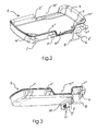
- the tray 4 is shown in a perspective view. It can be seen that the loading axis 7 is embodied in three sub-axes 7, 7 'and 7 ".Furthermore, the recesses 15' and 15" can be seen in the side wall 2 'and the receiving side 2 ", which should allow the telephone to be comfortable from the drawer 4.
- the telephone 18 must be pushed in a slight inclined position with the drawer open (4) under the retaining claws 14 'and 14 "., The user pushes the drawer 4 with the inserted phone rotating into the housing 12 against the resistance of the drawer 4 supporting spring mechanism 17th into the housing 12 of the device holder 1, then the contact plug 5 moves safely and precisely aligned with the contact socket of the telephone 18. Its movement is completed when the tray 4 is sunk into the housing 12 and held firmly by means of a locking mechanism.
- the drawer 4 is trough-shaped through the side wall 2 ', the receiving side 2 ", the side wall 3 and its opposite wall, and formed by a bottom.
- the cable connection 6 ' due to the flexibility of the cable, ensures the connection between the contact plug 5 integrated in the rider 6 and a communication connection accommodated in the housing 12.
- the communication port in the housing 12 leads to an internal or external electronics, such as a speakerphone.
- the tray 4 is seen in a perspective view from below, above all, an advantageous embodiment of the spring mechanism 17 comes to light, which ensures that the tray 4 is permanently pressed out of the housing 12 out.
- the spring of the spring mechanism 17 presses against the spring surface 9 'of the sliding shoulder 9 and this results in a force acting in the direction of the guide rail 10, the load 4 constantly communicates a torque about the loading axis 7.
- the housing 12 in this case forms a stop for the tray 4, which limits the Ausschwenkwinkel.
- the sliding shoulder 9 with the spring surface 9 'and the guide rail 10 are in this case attached to the bottom of the tray 4 visible.
- FIG. 4 shows the device holder 1 with an inserted telephone 18.
- the tray 4 is locked in this case in the housing 12 and can be released by pressing the release button 16.
- the phone 18 is inserted with its corners on the receiving side 2 "under the retaining claws 14 'and 14".
- the phone is also by the in his not shown side socket inserted contact plug 5 held.
- FIG. 6 shows the device holder 1 according to the invention with an inserted telephone 18, wherein the tray 4 is open.
- the phone 18 can be in this position of the open tray 4 with your fingers through the recesses 15 'and 15 "gripped and slightly rotating under the retaining claws 14' and 14" brought out.
Landscapes
- Engineering & Computer Science (AREA)
- Signal Processing (AREA)
- Computer Networks & Wireless Communication (AREA)
- Mechanical Engineering (AREA)
- Telephone Set Structure (AREA)
- Fittings On The Vehicle Exterior For Carrying Loads, And Devices For Holding Or Mounting Articles (AREA)
- Details Of Connecting Devices For Male And Female Coupling (AREA)
Abstract
Description
- Die Erfindung betrifft einen Gerätehalter für tragbare elektronische Geräte, insbesondere für Mobiltelefone zur Verbindung mit einer Freisprecheinrichtung für Fahrzeuge, mit elektrischen Kontaktanschlüssen an einer Aufnahmeseite des Gerätehalters zur Verbindung mit korrespondierenden Anschlüssen des Mobiltelefons, und mit Halteklauen zum Übergreifen von Abschnitten des elektronischen Gerätes.
- Es sind Telefonhalter bekannt, bei denen eine Kontaktbuchse des Telefons auf einen Kontaktstecker in dem Telefonhalter aufgesteckt wird, und das Telefon dann in den Halter eingedrückt wird, wodurch er meist mit seiner oberen Kante eine Rastmechanik betätigt und in der Halterung eingeschnappt wird. Um die Biegebeanspruchung der Kontaktelemente herabzusetzen wurden Halter entwickelt, die geteilt sind und der Kontaktstecker samt eines Teils der Halterung starr in ihr stehend um einen kleinen Winkel aus der Halterung herausgeschwenkt ist. Dadurch kann das Telefon in einer eindimensionalen Bewegung zunächst auf den Kontaktstecker aufgesetzt werden, und erst danach erfolgt die einrastende Bewegung zusammen mit dem drehbar gelagerten Teil der Halterung, bei der die Kontakte nicht mehr beansprucht werden, da sie bereits ineinander gesteckt worden sind. Es ist vorstellbar nach diesem Prinzip sowohl die meist anzutreffende vertikale Anordnung des Telefons vorzusehen, wie auch eine seitliche Lösung, wenn es die Anordnung der Kontaktbuchse seitlich an dem Telefon erforderlich macht. Diesen bekannten Lösungen haftet dennoch die Problematik der mechanischen Beanspruchung der Kontaktelemente an, sowie bei tiefer eingreifenden Kontaktsteckern das wachsende Problem mit der Verkantung des Kontaktsteckers gegenüber der Buchse.
- Eine weitere bekannte Anordnung eines Telefonhalters löst das gleiche Problem dadurch, dass das in zwei Teile geteilte Gehäuse des Telefonhalters aus ineinander verschiebbaren Teilgehäusen besteht. Wenn der Halter offen ist passt das Telefon seiner Länge nach problemlos hinein und kann auf den Kontaktstecker manuell aufgesteckt werden. Danach braucht man nur noch das eine der beiden verschiebbaren Halterteile manuell zu betätigen und zusammen zu schieben, wodurch eine Rastmechanik den Halter schließt. Hierbei muss der Benutzer manuell dafür sorgen, dass die Kontaktelemente genau genug aufeinander treffen und mit einer weiteren manuellen Bewegung der Halter einrastend geschlossen wird. Fehlbedienungen sind deshalb an der Tagesordnung.
- Die Aufgabe der vorliegenden Erfindung ist es deshalb einen wesentlich verbesserten Gerätehalter für tragbare elektronische Geräte, insbesondere für Mobiltelefone, anzubieten, bei dem eine verbesserte Führung, Kontaktierung und Halterung des elektronischen Gerätes sicher gestellt ist, und insbesondere die Kontaktierung der Steckverbindung automatisch und zuverlässig erfolgt.
- Die Aufgabe der Erfindung wird in einer ersten vorteilhaften Ausführungsform mit den Merkmalen des Anspruchs 1 gelöst, wobei das elektronische Gerät in eine schalenförmige Lade eingelegt wird, die im geöffneten Zustand des Gerätehalters um einen begrenzten Winkel aus der Halterung herausgeschwenkt ist. Hierfür ist die schalenförmige Lade drehbar um eine Achse gelagert, mit einer Federmechanik nach außen aus der Halterung gedrückt und aus einer Rastmechanik durch Betätigung eines Entriegelungsknopfes zuvor frei zugeben.
- Die Schwenkachse des Gerätehalters kann sowohl auf einer langen, meist vertikalen, wie einer kurzen, meist horizontalen, Seite des elektronischen Gerätes liegen, dort wo sich die Kontaktbuchse des Gerätes befindet. In der schwenkbaren Lade ist eine Öffnung vorgesehen, durch die hindurch der korrespondierende Kontaktstecker in die Lade hinein und herausgeführt werden kann. Der Kontaktstecker ist in einen Reiter integriert, der seinerseits ebenso um eine eigene Achse drehbar gelagert ist. Die Drehachsen der Lade und des Reiters verlaufen parallel und in einem Abstand voneinander versetzt, so dass hierdurch der Reiter durch die Drehbewegung der Lade mitgenommen und geführt wird, da er hierzu über eine Gleitschulter verfügt, mit der er in eine Führungsschiene unter dem Boden der Lade eingreift. Aufgrund der Geometrie der Anordnung erfolgt eine relative Bewegung des Reiters entlang des Bodens der Lade, so dass der Kontaktstecker bei herausgeschwenkter Lade in der Seitenwandöffnung der Lade versenkt wird, und beim Schließen der Lade auf seine maximale Länge in die Lade hinein eindringt. Hat man zuvor in geöffneter Stellung der Lade ein elektronisches Gerät eingelegt, so wird beim Schließen der Lade der Kontaktstecker ohne Gefahr einer Verkantung in die Kontaktbuchse des Gerätes genauestens geführt. Eine vorteilhafte Ausführung der Federmechanik ist so gestaltet, dass die Feder den Reiter und die Lade auseinander drückt, da hierdurch die Anzahl benötigter mechanischer Teile reduziert wird.
- Zusätzlich zu dem in die Kontaktbuchse des elektronischen Gerätes eingeführten Kontaktstecker halten in den Ecken der schalenförmigen Lade als Flächen ausgebildete Halteklauen das eingelegte elektronische Gerät gegen ein Herausfallen. Damit das eingelegte Gerät auch bei in Fahrzeugen aufkommenden Vibrationen und Erschütterungen nicht herausfällt, wird in einer weiteren vorteilhaften Ausbildung der Erfindung mindestens ein einrastender Riegel auf der gegenüber liegenden Seite des Gerätes gleichzeitig mit der Verriegelungsmechanik des Halters einrasten und das Gerät somit an mindestens einer seiner Kanten umfassen. Der Entriegelungsknopf wirkt beim Entriegeln zugleich auf den Geräteriegel und auf die Rastmechanik der Lade.
- Der Anschluss einer externen Antenne an ein Telefon erfolgt über einen der Kontakte in dem Kontaktstecker, oder alternativ über einen zusätzlichen Antennenstecker. Dieser Antennenstecker ist entweder auf der gleichen Seite des Telefons angebracht, oder es ist auf seiner Rückseite, und wird dann beim Einstecken des Telefons in die Lade kontaktiert.
- Im Folgenden wird die Erfindung anhand eines vorteilhaften Ausführungsbeispiels dargestellt. Gleiche oder gleich wirkenden Teile werden hierbei durch gleiche Bezugszeichen gekennzeichnet.
- Figur 1
- zeigt einen Querschnitt durch eine erste vorteilhafte Ausführungsform der Erfindung.
- Figur 2
- zeigt die Lade mit dem beweglichen Stecker
- Figur 3-
- die untere Ansicht der Lade
- Figur 4
- zeigt den Halter mit eingelegtem Telefon und geschlossener Lade
- Figur 5
- zeigt den Halter mit geschlossener Lade
- Figur 6
- zeigt den Halter mit eingelegtem Telefon und offener Lade
- In Figur 1 ist ein Querschnitt durch eine erste vorteilhafte Ausführung der Erfindung abgebildet. Unter a) ist ein Gerätehalter 1 bestehend aus einem Gehäuse 12 und einem im Scharnier 13 gelagerten Reiter 6, der mittels einer mit ihm in einer Einheit ausgebildeten Gleitschulter 9 in einer Führungsschiene 10 in der mittels Ladeachse 7 im Gehäuse 12 drehbar gelagerten Lade 4 geführt ist, zusehen. Die Gleitschiene für die Gleitschulter 9 unter dem Boden der Lade 4 ist mit der Führungsschiene 10 und mit von ihr gebildetem Hohlraum 11 gegeben.
- Die Lade 4 ist ihrerseits drehbar in entsprechenden, nicht dargestellten Scharnieren mit ihrer Ladeachse 7 gelagert, und ist hierdurch um einen Winkel aus dem Gehäuse 12 des Gerätehalters 1 heraus schwenkbar. Die Lade 4 ist mit einer nicht dargestellten einfachen Federmechanik aus dem Gehäuse 12 nach außen abgestützt, und wird im geschlossenen Zustand der Lade 4 von einer ebenso nicht dargestellten Verriegelungsmechanik festgehalten.
- Unter b) ist der Gerätehalter 1 geöffnet und es ist im Unterschied zur Momentaufnahme unter a) zu sehen, dass im aufgeklappten Zustand der Lade 4 der Reiter 6 mit seiner Gleitschulter 9 aus der Führungsschiene 10 herausgefahren worden ist. Diese Bewegung des Reiters 6 mit dem an ihm angebrachten und elektrisch angeschlossenen Kontaktstecker 5 ist durch die Drehbewegung der Lade 4 angetrieben und ergibt sich aufgrund der Versetzung der Drehachsen des Reiters 6, d.h. der Reiterachse 8, und der Ladeachse 7, sowie der Geometrie der Gleitschulter 9 und der Führungsschiene 10. Der Kontaktstecker 5 ist hierdurch in die Öffnung in der Aufnahmeseite 2" der Lade versunken. In diesem offenen Zustand kann ein Telefon 18 bequem in die Lade 4 eingelegt werden.
- Die dargestellte Lösung eignet sich zur Implementierung sowohl für seitlich, als auch für hochkantig einzulegenden Telefone.
- In Figur 2 ist die Lade 4 in einer perspektivischen Ansicht dargestellt. Zu sehen ist, dass die Ladeachse 7 in drei Teilachsen 7, 7' und 7" ausgeführt ist. Ferner sind die Aussparungen 15' und 15" in der Seitenwand 2' und der Aufnahmeseite 2" zu sehen, die es erlauben sollen das Telefon bequem aus der Lade 4 zu entnehmen und einzulegen. Die Halteklauen 14' und 14" sind als parallel zum Boden der Lade 4 angeordneten Flächen ausgebildet und in den Ecken der Lade 4 an der Aufnahmeseite 2" positioniert. Das Telefon 18 wird seitlich unter diese Halteklauen 14' und 14" schräg eingeführt und in den Ecken gegen Herausfallen gehalten.
- Das Telefon 18 muss in einer leichten Schräglage bei geöffneter Lade (4) unter die Halteklauen 14' und 14" eingeschoben werden. Drückt der Benutzer die Lade 4 mit dem eingelegten Telefon drehend in das Gehäuse 12 gegen den Widerstand der die Lade 4 abstützenden Federmechanik 17 ins Gehäuse 12 des Gerätehalters 1 hinein, dann fährt der Kontaktstecker 5 sicher und genau ausgerichtet in die Kontaktbuchse des Telefons 18 hinein. Seine Bewegung ist abgeschlossen, wenn die Lade 4 in das Gehäuse 12 versenkt und mittels einer Verriegelungsmechanik fest gehalten wird.
- Die Lade 4 ist wannenförmig durch die Seitenwand 2', die Aufnahmeseite 2", die Seitenwand 3 und der ihr gegenüber liegenden Wand, und von einem Boden gebildet.
- Der Kabelanschluss 6' sorgt durch die Biegsamkeit des Kabels für die Verbindung zwischen dem im Reiter 6 integrierten Kontacktstecker 5 und einem im Gehäuse 12 untergebrachten Kommunikationsanschluss. Der Kommunikationsanschluss im Gehäuse 12 führt zu einer internen oder externen Elektronik, beispielsweise einer Freisprecheinrichtung.
- In Figur 3 ist die Lade 4 in einer perspektivischen Ansicht von unten zu sehen, wobei vor allem eine vorteilhafte Ausführung der Federmechanik 17 zum Vorschein kommt, die dafür sorgt, dass die Lade 4 permanent aus dem Gehäuse 12 heraus gedrückt wird. Die Feder der Federmechanik 17 drückt gegen die Federfläche 9' der Gleitschulter 9 und hierdurch entsteht eine in der Richtung der Führungsschiene 10 wirkende Kraft, die der Lade 4 ständig einen Drehmoment um die Ladeachse 7 mitteilt.
- Das Gehäuse 12 bildet hierbei einen Anschlag für die Lade 4, der den Ausschwenkwinkel begrenzt. Die Gleitschulter 9 mit der Federfläche 9' und die Führungsschiene 10 sind hierbei sichtbar an dem Boden der Lade 4 angebracht.
- In Figur 4 ist der Gerätehalter 1 mit einem eingelegten Telefon 18 zu sehen. Die Lade 4 ist hierbei in das Gehäuse 12 eingerastet und kann durch Betätigung der Entriegelungstaste 16 frei gegeben werden. Das Telefon 18 ist mit seinen Ecken an der Aufnahmeseite 2" unter die Halteklauen 14' und 14" eingesteckt. Zusätzlich wird das Telefon auch durch den in seine nicht dargestellte seitliche Buchse eingeführten Kontaktstecker 5 gehalten.
- In Figur 5 ist der Gerätehalter 1 ohne Telefon mit geschlossener Lade 4 zu sehen, wobei der Kontaktstecker 5 als voll ausgefahren zu sehen ist. Die Aussparungen 15' und 15" sind sowohl in den Seitenwänden der Lade, wie in den Seitenwänden des Gehäuses 12 zwecks Handhabung des Telefons beim Einlegen und Herausnehmen ausgelassen worden.
- In Figur 6 ist der erfindungsgemäße Gerätehalter 1 mit einem eingelegten Telefon 18 zu sehen, wobei die Lade 4 geöffnet steht. Zu sehen ist unter der Lade 4 teilweise die Federmechanik 17. Das Telefon 18 kann in dieser Position der geöffneten Lade 4 mit den Fingern durch die Aussparungen 15' und 15" gegriffen und etwas drehend unter den Halteklauen 14' und 14" hervorgeholt werden.
-
- 1
- Gerätehalter
- 2'
- Seitenwand
- 2"
- Aufnahmeseite
- 3
- Seitenwand
- 4
- Lade
- 5
- Kontaktstecker
- 6
- Reiter
- 6'
- Kabelanschluss
- 7
- Ladeachse
- 8
- Reiterachse
- 9
- Gleitschulter
- 9'
- Federfläche
- 10
- Führungsschiene
- 11
- Hohlraum
- 12
- Gehäuse
- 13
- Scharnier
- 14' 14"
- Halteklauen
- 15' 15"
- Aussparung
- 16
- Entriegelungsknopf
- 17
- Federmechanik
- 18
- Telefon
Claims (11)
- Gerätehalter (1) für tragbare elektronische Geräte, insbesondere für Telefone (18) zur Verbindung mit einer Freisprecheinrichtung für Kraftfahrzeuge, mit elektrischen Kontaktanschlüssen an einer Aufnahmeseite (2") des Gerätehalters (1) zur Verbindung mit korrespondierenden Anschlüssen des elektronischen Gerätes, mit einer um eine Ladeachse (7) schwenkbaren Lade (4) mit senkrecht zum Boden der Lade (4) stehenden Seitenwänden (2', 3) und mit in den Ecken der Lade ausgebildeten Halteklauen (14', 14") zum Übergreifen von Abschnitten des elektronischen Gerätes, dadurch gekennzeichnet, dass die im Gerätehalter (1) schwenkbar gelagerte Lade (4) mindestens einen durch eine Öffnung in der Aufnahmeseite (2") hindurch beweglich gelagerten Kontaktstecker (5) aufweist, der in einem Reiter (6) integriert ist, und der Reiter (6) drehbar im Gehäuse (12) des Gerätehalters (1) gelagert ist, wobei die Reiterachse (8) des Reiters (6) und die Ladeachse (7) im Gehäuse (12) des Gerätehalters (1) parallel und in einem Abstand voneinander versetzt verlaufen, und der Reiter (6) mit einer Gleitschulter (9) in den Hohlraum (11) einer quer zur Ladeachse (7) verlaufenden Führungsschiene (10) unter dem Boden der Lade (4) frei gleitend eingreift und sich entlang des schwenkbaren Bodens der Lade (4) führen lässt.
- Gerätehalter (1) nach Anspruch 1, dadurch gekennzeichnet, dass die Lade (4) eine gegenüber der Aufnahmeseite (2") liegende Seitenwand (2') aufweist, und sie beide je eine Aussparung (15', 15") im mittleren Bereich aufweisen.
- Gerätehalter (1) nach Anspruch 1, dadurch gekennzeichnet, dass der Kontaktstecker (5) mindestens zwei Kontakte aufweist.
- Gerätehalter (1) nach Anspruch 1, dadurch gekennzeichnet, dass die schwenkbare Lade (4) mittels einer Federmechanik (17) aus dem Gehäuse (12) des Gerätehalters (1) herausgeschoben wird.
- Gerätehalter (1) nach Anspruch 1, dadurch gekennzeichnet, dass die Halteklauen (14', 14"), die sich in den Ecken der Lade (4) befinden, als Flächen ausgebildet sind.
- Gerätehalter (1) nach Anspruch 1, dadurch gekennzeichnet, dass in den Seitenwänden des Gehäuses (12) Aussparungen vorgesehen sind, die formschlüssig mit den Aussparungen (15' und 15") der Lade (4) fluchten, wenn diese geschlossen ist.
- Gerätehalter (1) nach Anspruch 1, dadurch gekennzeichnet, dass der Reiter (6) einen Kabelanschluss (6') aufweist, der aus einem biegsamen Kabel gefertigt ist und den Kontaktstecker (5) mit Kontakten im Gehäuse (12) verbindet, die mit einer Elektronik verbunden sind.
- Gerätehalter (1) nach Anspruch 1, dadurch gekennzeichnet, dass die Lade (4) mittels einer Verriegelungsmechanik in dem Gehäuse (12) festgehalten, und mittels eines Entriegelungsknopfes (16) zu entriegeln ist.
- Gerätehalter (1) nach Anspruch 1, dadurch gekennzeichnet, dass das Gehäuse (12) des Gerätehalters (1) einen Anschlag für die in ihm drehbar gelagerte Lade (4) bildet, wodurch der Ausschwenkwinkel der Lade (4) begrenzt ist.
- Gerätehalter (1) nach Anspruch 1, dadurch gekennzeichnet, dass die Lade (4) und das Gehäuse (12) des Gerätehalters (1) eine zusätzliche Verriegelungsmechanik aufweisen, die das Telefon (18) einrastend verriegelt, und die Entriegelung hierfür durch Entriegelungsknopf (16) der Verriegelungsmechanik der Lade (4) erfolgt.
- Gerätehalter (1) nach einem der vorhergehenden Ansprüche, dadurch gekennzeichnet, dass mindestens ein Kontaktanschluss ein Antennenanschluss ist.
Applications Claiming Priority (1)
| Application Number | Priority Date | Filing Date | Title |
|---|---|---|---|
| DE102006012763A DE102006012763B3 (de) | 2006-03-17 | 2006-03-17 | Gerätehalter mit einem beweglichen Kontaktstecker |
Publications (3)
| Publication Number | Publication Date |
|---|---|
| EP1835706A2 true EP1835706A2 (de) | 2007-09-19 |
| EP1835706A3 EP1835706A3 (de) | 2011-03-02 |
| EP1835706B1 EP1835706B1 (de) | 2012-02-08 |
Family
ID=38179840
Family Applications (1)
| Application Number | Title | Priority Date | Filing Date |
|---|---|---|---|
| EP07460005A Not-in-force EP1835706B1 (de) | 2006-03-17 | 2007-03-14 | Gerätehalter mit einem beweglichen Kontaktstecker |
Country Status (4)
| Country | Link |
|---|---|
| US (1) | US7801572B2 (de) |
| EP (1) | EP1835706B1 (de) |
| AT (1) | ATE545267T1 (de) |
| DE (1) | DE102006012763B3 (de) |
Cited By (6)
| Publication number | Priority date | Publication date | Assignee | Title |
|---|---|---|---|---|
| EP2080672A1 (de) * | 2008-01-20 | 2009-07-22 | Bury Sp.z.o.o | Mobiltelefonhalter mit seitlichen Anschlüssen, insbesondere für ein Fahrzeug |
| EP2159107A1 (de) * | 2008-08-21 | 2010-03-03 | Bury Sp.z.o.o | Mobiltelefonhalter mit seitlichem Stromanschluss, speziell für ein mechanisches Fahrzeug |
| EP2325049A1 (de) * | 2009-11-23 | 2011-05-25 | BURY Sp. z o.o. | Mobiltelefonhalter mit seitlichen Anschlüssen |
| EP2640044A1 (de) * | 2012-03-13 | 2013-09-18 | Samsung Electronics Co., Ltd | Universelle Dockingstation für tragbares Telefon |
| EP2241092A4 (de) * | 2008-01-10 | 2014-01-15 | Aria Entpr Inc | Einstellbares modulares multifunktions-kommunikationsgerät |
| ITTO20130453A1 (it) * | 2013-06-03 | 2014-12-04 | Fiat Group Automobiles Spa | Gruppo di supporto e trattenimento per un dispositivo elettronico portatile, e plancia di veicolo provvista di tale gruppo di supporto e trattenimento |
Families Citing this family (19)
| Publication number | Priority date | Publication date | Assignee | Title |
|---|---|---|---|---|
| DE102007033162A1 (de) * | 2007-07-17 | 2008-07-31 | Audi Ag | Geräteanordnung zum Anschluss eines mobilgen Endgerätes in einem Fahrzeug |
| DE102007037944B4 (de) * | 2007-08-11 | 2010-04-08 | Paragon Ag | Cradle für Mobiltelefone |
| US8306579B2 (en) * | 2009-07-29 | 2012-11-06 | Motorola Solutions, Inc. | Vehicular adapter apparatus |
| TWM394026U (en) * | 2010-07-28 | 2010-12-11 | Jin-Sheng Lin | Protective cover containing built-in amplifying channel |
| US8929065B2 (en) * | 2011-08-23 | 2015-01-06 | L&P Property Management Company | Docking station with ruggedized case |
| US8867202B2 (en) | 2011-08-23 | 2014-10-21 | L&P Property Management Company | Docking station |
| US9036361B2 (en) | 2012-01-23 | 2015-05-19 | Honeywell International Inc. | Avionic media systems including actuated media docking stations and over-center locking mechanisms suitable for usage therein |
| WO2013171367A1 (en) * | 2012-05-14 | 2013-11-21 | Cassidian Finland Oy | Cradle for a mobile terminal |
| US9455596B2 (en) | 2012-10-16 | 2016-09-27 | Ford Global Technologies, Llc | System and method for reducing interference between wireless charging and amplitude modulation reception |
| US9124124B2 (en) | 2012-10-16 | 2015-09-01 | Ford Global Technologies, Llc | System and method for reducing interference during wireless charging |
| US9148033B2 (en) | 2012-12-21 | 2015-09-29 | Ford Global Technologies, Llc | System of securing a wide-range of devices during wireless charging |
| US9472963B2 (en) | 2013-02-06 | 2016-10-18 | Ford Global Technologies, Llc | Device for wireless charging having a plurality of wireless charging protocols |
| US9167062B1 (en) | 2014-03-13 | 2015-10-20 | Smart And How Llc | Holder for hand-held electronic communication device |
| US8861714B1 (en) * | 2014-03-13 | 2014-10-14 | Leonard M. Leibenhaut | Holder for hand-held electronic communication device |
| CN205039893U (zh) * | 2015-10-20 | 2016-02-17 | 朴振奎 | 一种手机支架 |
| US9710016B1 (en) | 2016-01-16 | 2017-07-18 | Bion Porzio | Docking station with securing apparatus and stand for electronic device |
| USD836646S1 (en) * | 2016-07-14 | 2018-12-25 | Clarion Technologies, Inc. | Device mount for scanner |
| JP7260842B1 (ja) | 2023-01-19 | 2023-04-19 | 富士通クライアントコンピューティング株式会社 | 接続装置 |
| DE102023002428A1 (de) * | 2023-06-16 | 2024-06-27 | Mercedes-Benz Group AG | Ablagekonzept für ein Mobiltelefon im Fahrzeug |
Family Cites Families (17)
| Publication number | Priority date | Publication date | Assignee | Title |
|---|---|---|---|---|
| DE4405506C2 (de) * | 1994-02-21 | 1996-04-18 | Aeg Mobile Communication | Halterung für ein Handfunktelefon |
| US5825874A (en) * | 1996-08-09 | 1998-10-20 | Nokia Mobile Phones Limited | Mobile telephone holder |
| DE19652826A1 (de) * | 1996-12-18 | 1998-06-25 | Nokia Mobile Phones Ltd | Haltevorrichtung für eine Kommunikationseinheit |
| JP2000505984A (ja) * | 1996-12-24 | 2000-05-16 | コーニンクレッカ フィリップス エレクトロニクス エヌ ヴィ | 電話送受話器用のホルダ並びにホルダ及び電話送受話器の組立体 |
| US6339699B1 (en) * | 1997-09-24 | 2002-01-15 | Harness System Technologies Research, Ltd. | Phone holder |
| GB2335460B (en) * | 1998-03-18 | 2002-04-10 | Nokia Mobile Phones Ltd | A holder for a portable electronic device |
| JP2908444B1 (ja) * | 1998-07-07 | 1999-06-21 | 静岡日本電気株式会社 | 携帯機器用ホルダ |
| DE19942935A1 (de) * | 1999-09-08 | 2001-03-15 | Siemens Ag | Halterung für mobiles Telekommunikations-Endgerät in einem Fahrzeug |
| DE19946746C2 (de) * | 1999-09-29 | 2001-08-02 | Siemens Ag | KFZ-Halterung für Mobilfunkgeräte |
| US6341218B1 (en) * | 1999-12-06 | 2002-01-22 | Cellport Systems, Inc. | Supporting and connecting a portable phone |
| TW525864U (en) * | 2001-10-03 | 2003-03-21 | Sheng-Shing Liau | Rapid assembly cellular phone charger |
| US6848662B2 (en) * | 2002-01-24 | 2005-02-01 | Zih Corp. | Secure latching system |
| US7162281B2 (en) * | 2002-02-22 | 2007-01-09 | Dong Joo Kim | Mobile phone holder |
| DE102004033897A1 (de) * | 2004-07-14 | 2006-02-16 | Daimlerchrysler Ag | Vorrichtung zur Aufnahme eines Telefons in einer in einem Fahrzeug vorgesehenen Mittelkonsole |
| US20080142651A1 (en) * | 2005-01-24 | 2008-06-19 | Ralf Tomasini | Cradle for Mobile Phones and Ejector Device Thereof |
| US7270435B2 (en) * | 2005-08-19 | 2007-09-18 | Beta Emblems & Dies Co., Ltd. | Mobile phone holder |
| KR100678215B1 (ko) * | 2006-04-07 | 2007-02-02 | 삼성전자주식회사 | 휴대 단말기 및 그의 슬라이딩 거치 장치 |
-
2006
- 2006-03-17 DE DE102006012763A patent/DE102006012763B3/de not_active Expired - Fee Related
-
2007
- 2007-03-14 AT AT07460005T patent/ATE545267T1/de active
- 2007-03-14 EP EP07460005A patent/EP1835706B1/de not_active Not-in-force
- 2007-03-17 US US11/687,634 patent/US7801572B2/en not_active Expired - Fee Related
Cited By (13)
| Publication number | Priority date | Publication date | Assignee | Title |
|---|---|---|---|---|
| EP2241092A4 (de) * | 2008-01-10 | 2014-01-15 | Aria Entpr Inc | Einstellbares modulares multifunktions-kommunikationsgerät |
| US9325817B2 (en) | 2008-01-10 | 2016-04-26 | Ziba Labs Llc | Customizable modular multi-function communication device |
| CN104038585A (zh) * | 2008-01-10 | 2014-09-10 | 济巴实验室有限公司 | 可定制的组合式多功能通信装置 |
| US8078237B2 (en) | 2008-01-20 | 2011-12-13 | Bury Sp. Z O.O. | Mobile phone holder with lateral connections, especially for a mechanical vehicle |
| EP2080672A1 (de) * | 2008-01-20 | 2009-07-22 | Bury Sp.z.o.o | Mobiltelefonhalter mit seitlichen Anschlüssen, insbesondere für ein Fahrzeug |
| EP2159107A1 (de) * | 2008-08-21 | 2010-03-03 | Bury Sp.z.o.o | Mobiltelefonhalter mit seitlichem Stromanschluss, speziell für ein mechanisches Fahrzeug |
| EP2325049A1 (de) * | 2009-11-23 | 2011-05-25 | BURY Sp. z o.o. | Mobiltelefonhalter mit seitlichen Anschlüssen |
| EP2640044A1 (de) * | 2012-03-13 | 2013-09-18 | Samsung Electronics Co., Ltd | Universelle Dockingstation für tragbares Telefon |
| US9318906B2 (en) | 2012-03-13 | 2016-04-19 | Samsung Electronics Co., Ltd. | Universal dock for portable phone |
| ITTO20130453A1 (it) * | 2013-06-03 | 2014-12-04 | Fiat Group Automobiles Spa | Gruppo di supporto e trattenimento per un dispositivo elettronico portatile, e plancia di veicolo provvista di tale gruppo di supporto e trattenimento |
| EP2810808A1 (de) * | 2013-06-03 | 2014-12-10 | Fiat Group Automobiles S.p.A. | Vorrichtung zum Tragen und Halten eines tragbaren elektronischen Gerätes |
| US9233649B2 (en) | 2013-06-03 | 2016-01-12 | Fiat Group Automobiles S.P.A. | Support and retention assembly for a portable electronic device, and dashboard provided with such a support and retention assembly |
| RU2617774C2 (ru) * | 2013-06-03 | 2017-04-26 | Фиат Груп Отомобилс С.П.А. | Опорное и удерживающее устройство для портативного электронного устройства и приборная панель, оснащенная таким опорным и удерживающим устройством |
Also Published As
| Publication number | Publication date |
|---|---|
| US20070293277A1 (en) | 2007-12-20 |
| EP1835706B1 (de) | 2012-02-08 |
| ATE545267T1 (de) | 2012-02-15 |
| US7801572B2 (en) | 2010-09-21 |
| EP1835706A3 (de) | 2011-03-02 |
| DE102006012763B3 (de) | 2007-10-18 |
Similar Documents
| Publication | Publication Date | Title |
|---|---|---|
| EP1835706B1 (de) | Gerätehalter mit einem beweglichen Kontaktstecker | |
| EP1973313B1 (de) | Fahrzeughalterung für ein Mobiltelefon | |
| DE102006011712B4 (de) | Tragbares elektronisches Gerät mit einer verriegelten Batterieabdeckung und Mechanismus zum Anheben der Abdeckung | |
| DE19540104A1 (de) | Elektrischer Steckverbinder sowie denselben verwendendes elektronisches Gerät | |
| DE19755621B4 (de) | Aufnahmevorrichtung für ein Handy in einem Kraftfahrzeug | |
| EP3012920B1 (de) | Elektrische steckdose | |
| EP2518980A2 (de) | Haltevorrichtung für ein Mobiltelefon | |
| DE102013106649B4 (de) | Halter für ein elektronisches Gerät | |
| DE202015003576U1 (de) | Elektrischer Stecker | |
| DE202008006884U1 (de) | Träger für eine Steckdose | |
| DE212013000180U1 (de) | Steckeraufbau mit der Möglichkeit zur Gestaltänderung | |
| DE102015114138A1 (de) | Steckverbinderteil mit einem Verriegelungselement | |
| EP2095520B1 (de) | Haltevorrichtung für ein elektronisches gerät | |
| DE60103934T2 (de) | Kommunikationseinrichtung | |
| EP1821501A1 (de) | Haltevorrichtung für ein elektronisches Gerät | |
| DE29912359U1 (de) | Verbindungsanordnung zwischen einem tragbaren Telefonhalter und einem fest installierbaren Basishalter sowie Telefonhalter und Basishalter zur Verwendung in der Verbindungsanordnung | |
| EP1055562A2 (de) | Halterung für Funktelefon | |
| EP2523282B1 (de) | Zentralscheibe eines elektrischen Installationsgerätes zum Ablegen und elektrischen Aufladen eines mobilen Audio- und Kommunikationsgerätes | |
| DE102007054451A1 (de) | Haltevorrichtung für ein elektronisches Gerät | |
| DE4134650C1 (en) | Handset esp. for cordless telephone - has integrated loudspeaker at one end and microphone in pivotable flap at other end | |
| DE102005025530B3 (de) | Gerätehalter | |
| DE4008618C2 (de) | ||
| DE202006020089U1 (de) | Gerätehalter mit einem beweglichen Kontaktstecker | |
| DE10162069B4 (de) | Einrichtung für eine formschlüssige Aufnahme eines elektronischen Gerätes | |
| DE102006005111B4 (de) | Telefonhalter für ein Mobiltelefon |
Legal Events
| Date | Code | Title | Description |
|---|---|---|---|
| PUAI | Public reference made under article 153(3) epc to a published international application that has entered the european phase |
Free format text: ORIGINAL CODE: 0009012 |
|
| AK | Designated contracting states |
Kind code of ref document: A2 Designated state(s): AT BE BG CH CY CZ DE DK EE ES FI FR GB GR HU IE IS IT LI LT LU LV MC MT NL PL PT RO SE SI SK TR |
|
| AX | Request for extension of the european patent |
Extension state: AL BA HR MK YU |
|
| 17P | Request for examination filed |
Effective date: 20071109 |
|
| PUAL | Search report despatched |
Free format text: ORIGINAL CODE: 0009013 |
|
| AK | Designated contracting states |
Kind code of ref document: A3 Designated state(s): AT BE BG CH CY CZ DE DK EE ES FI FR GB GR HU IE IS IT LI LT LU LV MC MT NL PL PT RO SE SI SK TR |
|
| AX | Request for extension of the european patent |
Extension state: AL BA HR MK RS |
|
| AKX | Designation fees paid |
Designated state(s): AT BE BG CH CY CZ DE DK EE ES FI FR GB GR HU IE IS IT LI LT LU LV MC MT NL PL PT RO SE SI SK TR |
|
| GRAP | Despatch of communication of intention to grant a patent |
Free format text: ORIGINAL CODE: EPIDOSNIGR1 |
|
| GRAS | Grant fee paid |
Free format text: ORIGINAL CODE: EPIDOSNIGR3 |
|
| GRAA | (expected) grant |
Free format text: ORIGINAL CODE: 0009210 |
|
| AK | Designated contracting states |
Kind code of ref document: B1 Designated state(s): AT BE BG CH CY CZ DE DK EE ES FI FR GB GR HU IE IS IT LI LT LU LV MC MT NL PL PT RO SE SI SK TR |
|
| REG | Reference to a national code |
Ref country code: GB Ref legal event code: FG4D Free format text: NOT ENGLISH |
|
| REG | Reference to a national code |
Ref country code: CH Ref legal event code: EP Ref country code: AT Ref legal event code: REF Ref document number: 545267 Country of ref document: AT Kind code of ref document: T Effective date: 20120215 |
|
| REG | Reference to a national code |
Ref country code: DE Ref legal event code: R096 Ref document number: 502007009250 Country of ref document: DE Effective date: 20120405 |
|
| REG | Reference to a national code |
Ref country code: NL Ref legal event code: VDEP Effective date: 20120208 |
|
| LTIE | Lt: invalidation of european patent or patent extension |
Effective date: 20120208 |
|
| PG25 | Lapsed in a contracting state [announced via postgrant information from national office to epo] |
Ref country code: NL Free format text: LAPSE BECAUSE OF FAILURE TO SUBMIT A TRANSLATION OF THE DESCRIPTION OR TO PAY THE FEE WITHIN THE PRESCRIBED TIME-LIMIT Effective date: 20120208 Ref country code: IS Free format text: LAPSE BECAUSE OF FAILURE TO SUBMIT A TRANSLATION OF THE DESCRIPTION OR TO PAY THE FEE WITHIN THE PRESCRIBED TIME-LIMIT Effective date: 20120608 Ref country code: LT Free format text: LAPSE BECAUSE OF FAILURE TO SUBMIT A TRANSLATION OF THE DESCRIPTION OR TO PAY THE FEE WITHIN THE PRESCRIBED TIME-LIMIT Effective date: 20120208 |
|
| REG | Reference to a national code |
Ref country code: IE Ref legal event code: FD4D |
|
| PG25 | Lapsed in a contracting state [announced via postgrant information from national office to epo] |
Ref country code: GR Free format text: LAPSE BECAUSE OF FAILURE TO SUBMIT A TRANSLATION OF THE DESCRIPTION OR TO PAY THE FEE WITHIN THE PRESCRIBED TIME-LIMIT Effective date: 20120509 Ref country code: LV Free format text: LAPSE BECAUSE OF FAILURE TO SUBMIT A TRANSLATION OF THE DESCRIPTION OR TO PAY THE FEE WITHIN THE PRESCRIBED TIME-LIMIT Effective date: 20120208 Ref country code: PL Free format text: LAPSE BECAUSE OF FAILURE TO SUBMIT A TRANSLATION OF THE DESCRIPTION OR TO PAY THE FEE WITHIN THE PRESCRIBED TIME-LIMIT Effective date: 20120208 Ref country code: FI Free format text: LAPSE BECAUSE OF FAILURE TO SUBMIT A TRANSLATION OF THE DESCRIPTION OR TO PAY THE FEE WITHIN THE PRESCRIBED TIME-LIMIT Effective date: 20120208 Ref country code: PT Free format text: LAPSE BECAUSE OF FAILURE TO SUBMIT A TRANSLATION OF THE DESCRIPTION OR TO PAY THE FEE WITHIN THE PRESCRIBED TIME-LIMIT Effective date: 20120608 |
|
| PG25 | Lapsed in a contracting state [announced via postgrant information from national office to epo] |
Ref country code: CY Free format text: LAPSE BECAUSE OF FAILURE TO SUBMIT A TRANSLATION OF THE DESCRIPTION OR TO PAY THE FEE WITHIN THE PRESCRIBED TIME-LIMIT Effective date: 20120208 |
|
| BERE | Be: lapsed |
Owner name: BURY SP. Z O.O. Effective date: 20120331 |
|
| PG25 | Lapsed in a contracting state [announced via postgrant information from national office to epo] |
Ref country code: CZ Free format text: LAPSE BECAUSE OF FAILURE TO SUBMIT A TRANSLATION OF THE DESCRIPTION OR TO PAY THE FEE WITHIN THE PRESCRIBED TIME-LIMIT Effective date: 20120208 Ref country code: DK Free format text: LAPSE BECAUSE OF FAILURE TO SUBMIT A TRANSLATION OF THE DESCRIPTION OR TO PAY THE FEE WITHIN THE PRESCRIBED TIME-LIMIT Effective date: 20120208 Ref country code: SE Free format text: LAPSE BECAUSE OF FAILURE TO SUBMIT A TRANSLATION OF THE DESCRIPTION OR TO PAY THE FEE WITHIN THE PRESCRIBED TIME-LIMIT Effective date: 20120208 Ref country code: SI Free format text: LAPSE BECAUSE OF FAILURE TO SUBMIT A TRANSLATION OF THE DESCRIPTION OR TO PAY THE FEE WITHIN THE PRESCRIBED TIME-LIMIT Effective date: 20120208 Ref country code: RO Free format text: LAPSE BECAUSE OF FAILURE TO SUBMIT A TRANSLATION OF THE DESCRIPTION OR TO PAY THE FEE WITHIN THE PRESCRIBED TIME-LIMIT Effective date: 20120208 Ref country code: IE Free format text: LAPSE BECAUSE OF FAILURE TO SUBMIT A TRANSLATION OF THE DESCRIPTION OR TO PAY THE FEE WITHIN THE PRESCRIBED TIME-LIMIT Effective date: 20120208 Ref country code: EE Free format text: LAPSE BECAUSE OF FAILURE TO SUBMIT A TRANSLATION OF THE DESCRIPTION OR TO PAY THE FEE WITHIN THE PRESCRIBED TIME-LIMIT Effective date: 20120208 Ref country code: MC Free format text: LAPSE BECAUSE OF NON-PAYMENT OF DUE FEES Effective date: 20120331 |
|
| REG | Reference to a national code |
Ref country code: CH Ref legal event code: PL |
|
| PG25 | Lapsed in a contracting state [announced via postgrant information from national office to epo] |
Ref country code: IT Free format text: LAPSE BECAUSE OF FAILURE TO SUBMIT A TRANSLATION OF THE DESCRIPTION OR TO PAY THE FEE WITHIN THE PRESCRIBED TIME-LIMIT Effective date: 20120208 Ref country code: SK Free format text: LAPSE BECAUSE OF FAILURE TO SUBMIT A TRANSLATION OF THE DESCRIPTION OR TO PAY THE FEE WITHIN THE PRESCRIBED TIME-LIMIT Effective date: 20120208 |
|
| PLBE | No opposition filed within time limit |
Free format text: ORIGINAL CODE: 0009261 |
|
| STAA | Information on the status of an ep patent application or granted ep patent |
Free format text: STATUS: NO OPPOSITION FILED WITHIN TIME LIMIT |
|
| REG | Reference to a national code |
Ref country code: FR Ref legal event code: ST Effective date: 20121130 |
|
| 26N | No opposition filed |
Effective date: 20121109 |
|
| REG | Reference to a national code |
Ref country code: DE Ref legal event code: R119 Ref document number: 502007009250 Country of ref document: DE Effective date: 20121002 |
|
| GBPC | Gb: european patent ceased through non-payment of renewal fee |
Effective date: 20120508 |
|
| PG25 | Lapsed in a contracting state [announced via postgrant information from national office to epo] |
Ref country code: LI Free format text: LAPSE BECAUSE OF NON-PAYMENT OF DUE FEES Effective date: 20120331 Ref country code: BE Free format text: LAPSE BECAUSE OF NON-PAYMENT OF DUE FEES Effective date: 20120331 Ref country code: FR Free format text: LAPSE BECAUSE OF NON-PAYMENT OF DUE FEES Effective date: 20120410 Ref country code: CH Free format text: LAPSE BECAUSE OF NON-PAYMENT OF DUE FEES Effective date: 20120331 |
|
| PG25 | Lapsed in a contracting state [announced via postgrant information from national office to epo] |
Ref country code: GB Free format text: LAPSE BECAUSE OF NON-PAYMENT OF DUE FEES Effective date: 20120508 Ref country code: ES Free format text: LAPSE BECAUSE OF FAILURE TO SUBMIT A TRANSLATION OF THE DESCRIPTION OR TO PAY THE FEE WITHIN THE PRESCRIBED TIME-LIMIT Effective date: 20120519 |
|
| REG | Reference to a national code |
Ref country code: AT Ref legal event code: MM01 Ref document number: 545267 Country of ref document: AT Kind code of ref document: T Effective date: 20120314 |
|
| PG25 | Lapsed in a contracting state [announced via postgrant information from national office to epo] |
Ref country code: AT Free format text: LAPSE BECAUSE OF NON-PAYMENT OF DUE FEES Effective date: 20120314 Ref country code: BG Free format text: LAPSE BECAUSE OF FAILURE TO SUBMIT A TRANSLATION OF THE DESCRIPTION OR TO PAY THE FEE WITHIN THE PRESCRIBED TIME-LIMIT Effective date: 20120508 Ref country code: MT Free format text: LAPSE BECAUSE OF FAILURE TO SUBMIT A TRANSLATION OF THE DESCRIPTION OR TO PAY THE FEE WITHIN THE PRESCRIBED TIME-LIMIT Effective date: 20120208 |
|
| PG25 | Lapsed in a contracting state [announced via postgrant information from national office to epo] |
Ref country code: TR Free format text: LAPSE BECAUSE OF FAILURE TO SUBMIT A TRANSLATION OF THE DESCRIPTION OR TO PAY THE FEE WITHIN THE PRESCRIBED TIME-LIMIT Effective date: 20120208 |
|
| PG25 | Lapsed in a contracting state [announced via postgrant information from national office to epo] |
Ref country code: LU Free format text: LAPSE BECAUSE OF NON-PAYMENT OF DUE FEES Effective date: 20120314 |
|
| PG25 | Lapsed in a contracting state [announced via postgrant information from national office to epo] |
Ref country code: HU Free format text: LAPSE BECAUSE OF FAILURE TO SUBMIT A TRANSLATION OF THE DESCRIPTION OR TO PAY THE FEE WITHIN THE PRESCRIBED TIME-LIMIT Effective date: 20070314 |
|
| PG25 | Lapsed in a contracting state [announced via postgrant information from national office to epo] |
Ref country code: DE Free format text: LAPSE BECAUSE OF FAILURE TO SUBMIT A TRANSLATION OF THE DESCRIPTION OR TO PAY THE FEE WITHIN THE PRESCRIBED TIME-LIMIT Effective date: 20121002 |