EP1832535B1 - Appareil de transport de four dégraissant et procédé de fabrication d'un corps structuré en nid d'abeille - Google Patents
Appareil de transport de four dégraissant et procédé de fabrication d'un corps structuré en nid d'abeille Download PDFInfo
- Publication number
- EP1832535B1 EP1832535B1 EP07002219A EP07002219A EP1832535B1 EP 1832535 B1 EP1832535 B1 EP 1832535B1 EP 07002219 A EP07002219 A EP 07002219A EP 07002219 A EP07002219 A EP 07002219A EP 1832535 B1 EP1832535 B1 EP 1832535B1
- Authority
- EP
- European Patent Office
- Prior art keywords
- suction
- honeycomb
- degreasing
- molded bodies
- molded body
- Prior art date
- Legal status (The legal status is an assumption and is not a legal conclusion. Google has not performed a legal analysis and makes no representation as to the accuracy of the status listed.)
- Active
Links
- 238000005238 degreasing Methods 0.000 title claims description 154
- 238000000034 method Methods 0.000 title claims description 109
- 238000004519 manufacturing process Methods 0.000 title claims description 44
- 239000000919 ceramic Substances 0.000 claims description 90
- 230000007246 mechanism Effects 0.000 claims description 88
- 238000010304 firing Methods 0.000 claims description 22
- JOYRKODLDBILNP-UHFFFAOYSA-N Ethyl urethane Chemical compound CCOC(N)=O JOYRKODLDBILNP-UHFFFAOYSA-N 0.000 claims description 7
- 238000000465 moulding Methods 0.000 claims description 6
- 230000032258 transport Effects 0.000 claims description 5
- 238000005192 partition Methods 0.000 claims description 2
- 239000002994 raw material Substances 0.000 claims description 2
- 230000008569 process Effects 0.000 description 71
- 239000000463 material Substances 0.000 description 29
- 210000004027 cell Anatomy 0.000 description 25
- 239000011148 porous material Substances 0.000 description 23
- 239000010410 layer Substances 0.000 description 22
- 239000003566 sealing material Substances 0.000 description 21
- 239000000203 mixture Substances 0.000 description 20
- PNEYBMLMFCGWSK-UHFFFAOYSA-N aluminium oxide Inorganic materials [O-2].[O-2].[O-2].[Al+3].[Al+3] PNEYBMLMFCGWSK-UHFFFAOYSA-N 0.000 description 17
- HBMJWWWQQXIZIP-UHFFFAOYSA-N silicon carbide Chemical compound [Si+]#[C-] HBMJWWWQQXIZIP-UHFFFAOYSA-N 0.000 description 15
- 239000000843 powder Substances 0.000 description 14
- 229910010271 silicon carbide Inorganic materials 0.000 description 13
- 239000011230 binding agent Substances 0.000 description 12
- 239000003054 catalyst Substances 0.000 description 12
- 238000001035 drying Methods 0.000 description 12
- 229910010293 ceramic material Inorganic materials 0.000 description 11
- 239000007789 gas Substances 0.000 description 11
- 239000002245 particle Substances 0.000 description 10
- 238000009826 distribution Methods 0.000 description 9
- -1 polyethylene Polymers 0.000 description 9
- 239000011347 resin Substances 0.000 description 9
- 229920005989 resin Polymers 0.000 description 9
- 239000012790 adhesive layer Substances 0.000 description 7
- 230000003028 elevating effect Effects 0.000 description 7
- 238000001125 extrusion Methods 0.000 description 7
- 239000000243 solution Substances 0.000 description 7
- 210000002421 cell wall Anatomy 0.000 description 6
- 238000005520 cutting process Methods 0.000 description 6
- XUIMIQQOPSSXEZ-UHFFFAOYSA-N Silicon Chemical compound [Si] XUIMIQQOPSSXEZ-UHFFFAOYSA-N 0.000 description 5
- 239000000314 lubricant Substances 0.000 description 5
- 239000011812 mixed powder Substances 0.000 description 5
- 238000002156 mixing Methods 0.000 description 5
- BASFCYQUMIYNBI-UHFFFAOYSA-N platinum Chemical compound [Pt] BASFCYQUMIYNBI-UHFFFAOYSA-N 0.000 description 5
- 239000000523 sample Substances 0.000 description 5
- 229910052710 silicon Inorganic materials 0.000 description 5
- 239000010703 silicon Substances 0.000 description 5
- PEDCQBHIVMGVHV-UHFFFAOYSA-N Glycerine Chemical compound OCC(O)CO PEDCQBHIVMGVHV-UHFFFAOYSA-N 0.000 description 4
- OKKJLVBELUTLKV-UHFFFAOYSA-N Methanol Chemical compound OC OKKJLVBELUTLKV-UHFFFAOYSA-N 0.000 description 4
- 239000000470 constituent Substances 0.000 description 4
- KZHJGOXRZJKJNY-UHFFFAOYSA-N dioxosilane;oxo(oxoalumanyloxy)alumane Chemical compound O=[Si]=O.O=[Si]=O.O=[Al]O[Al]=O.O=[Al]O[Al]=O.O=[Al]O[Al]=O KZHJGOXRZJKJNY-UHFFFAOYSA-N 0.000 description 4
- 239000007788 liquid Substances 0.000 description 4
- 229910052751 metal Inorganic materials 0.000 description 4
- 239000002184 metal Substances 0.000 description 4
- 229920000609 methyl cellulose Polymers 0.000 description 4
- 239000001923 methylcellulose Substances 0.000 description 4
- 235000010981 methylcellulose Nutrition 0.000 description 4
- 229910052863 mullite Inorganic materials 0.000 description 4
- 239000004014 plasticizer Substances 0.000 description 4
- 238000007789 sealing Methods 0.000 description 4
- UHOVQNZJYSORNB-UHFFFAOYSA-N Benzene Chemical compound C1=CC=CC=C1 UHOVQNZJYSORNB-UHFFFAOYSA-N 0.000 description 3
- 229920002134 Carboxymethyl cellulose Polymers 0.000 description 3
- LYCAIKOWRPUZTN-UHFFFAOYSA-N Ethylene glycol Chemical compound OCCO LYCAIKOWRPUZTN-UHFFFAOYSA-N 0.000 description 3
- 239000001768 carboxy methyl cellulose Substances 0.000 description 3
- 235000010948 carboxy methyl cellulose Nutrition 0.000 description 3
- 239000008112 carboxymethyl-cellulose Substances 0.000 description 3
- 239000002270 dispersing agent Substances 0.000 description 3
- 229920001971 elastomer Polymers 0.000 description 3
- 239000012784 inorganic fiber Substances 0.000 description 3
- 239000010954 inorganic particle Substances 0.000 description 3
- 239000005060 rubber Substances 0.000 description 3
- 229920002803 thermoplastic polyurethane Polymers 0.000 description 3
- XLYOFNOQVPJJNP-UHFFFAOYSA-N water Substances O XLYOFNOQVPJJNP-UHFFFAOYSA-N 0.000 description 3
- 229910000505 Al2TiO5 Inorganic materials 0.000 description 2
- 229910052582 BN Inorganic materials 0.000 description 2
- PZNSFCLAULLKQX-UHFFFAOYSA-N Boron nitride Chemical compound N#B PZNSFCLAULLKQX-UHFFFAOYSA-N 0.000 description 2
- OKTJSMMVPCPJKN-UHFFFAOYSA-N Carbon Chemical compound [C] OKTJSMMVPCPJKN-UHFFFAOYSA-N 0.000 description 2
- 229920000049 Carbon (fiber) Polymers 0.000 description 2
- XEEYBQQBJWHFJM-UHFFFAOYSA-N Iron Chemical compound [Fe] XEEYBQQBJWHFJM-UHFFFAOYSA-N 0.000 description 2
- PXHVJJICTQNCMI-UHFFFAOYSA-N Nickel Chemical compound [Ni] PXHVJJICTQNCMI-UHFFFAOYSA-N 0.000 description 2
- 239000004698 Polyethylene Substances 0.000 description 2
- 239000004743 Polypropylene Substances 0.000 description 2
- 239000004793 Polystyrene Substances 0.000 description 2
- 229910052581 Si3N4 Inorganic materials 0.000 description 2
- VYPSYNLAJGMNEJ-UHFFFAOYSA-N Silicium dioxide Chemical compound O=[Si]=O VYPSYNLAJGMNEJ-UHFFFAOYSA-N 0.000 description 2
- MCMNRKCIXSYSNV-UHFFFAOYSA-N Zirconium dioxide Chemical compound O=[Zr]=O MCMNRKCIXSYSNV-UHFFFAOYSA-N 0.000 description 2
- NIXOWILDQLNWCW-UHFFFAOYSA-N acrylic acid group Chemical group C(C=C)(=O)O NIXOWILDQLNWCW-UHFFFAOYSA-N 0.000 description 2
- 230000003213 activating effect Effects 0.000 description 2
- 150000005215 alkyl ethers Chemical class 0.000 description 2
- 229910052782 aluminium Inorganic materials 0.000 description 2
- XAGFODPZIPBFFR-UHFFFAOYSA-N aluminium Chemical compound [Al] XAGFODPZIPBFFR-UHFFFAOYSA-N 0.000 description 2
- JLDSOYXADOWAKB-UHFFFAOYSA-N aluminium nitrate Chemical compound [Al+3].[O-][N+]([O-])=O.[O-][N+]([O-])=O.[O-][N+]([O-])=O JLDSOYXADOWAKB-UHFFFAOYSA-N 0.000 description 2
- 239000012300 argon atmosphere Substances 0.000 description 2
- 239000004917 carbon fiber Substances 0.000 description 2
- 239000003795 chemical substances by application Substances 0.000 description 2
- 239000003426 co-catalyst Substances 0.000 description 2
- 229910052878 cordierite Inorganic materials 0.000 description 2
- 230000008878 coupling Effects 0.000 description 2
- 238000010168 coupling process Methods 0.000 description 2
- 238000005859 coupling reaction Methods 0.000 description 2
- 238000002276 dielectric drying Methods 0.000 description 2
- 235000014113 dietary fatty acids Nutrition 0.000 description 2
- JSKIRARMQDRGJZ-UHFFFAOYSA-N dimagnesium dioxido-bis[(1-oxido-3-oxo-2,4,6,8,9-pentaoxa-1,3-disila-5,7-dialuminabicyclo[3.3.1]nonan-7-yl)oxy]silane Chemical compound [Mg++].[Mg++].[O-][Si]([O-])(O[Al]1O[Al]2O[Si](=O)O[Si]([O-])(O1)O2)O[Al]1O[Al]2O[Si](=O)O[Si]([O-])(O1)O2 JSKIRARMQDRGJZ-UHFFFAOYSA-N 0.000 description 2
- 230000000694 effects Effects 0.000 description 2
- 239000000194 fatty acid Substances 0.000 description 2
- 229930195729 fatty acid Natural products 0.000 description 2
- 150000004665 fatty acids Chemical class 0.000 description 2
- 239000000835 fiber Substances 0.000 description 2
- 239000011521 glass Substances 0.000 description 2
- 235000011187 glycerol Nutrition 0.000 description 2
- 239000010439 graphite Substances 0.000 description 2
- 229910002804 graphite Inorganic materials 0.000 description 2
- 238000007602 hot air drying Methods 0.000 description 2
- 150000002736 metal compounds Chemical class 0.000 description 2
- 229910017604 nitric acid Inorganic materials 0.000 description 2
- 150000004767 nitrides Chemical class 0.000 description 2
- 229910052697 platinum Inorganic materials 0.000 description 2
- AABBHSMFGKYLKE-SNAWJCMRSA-N propan-2-yl (e)-but-2-enoate Chemical compound C\C=C\C(=O)OC(C)C AABBHSMFGKYLKE-SNAWJCMRSA-N 0.000 description 2
- RMAQACBXLXPBSY-UHFFFAOYSA-N silicic acid Chemical compound O[Si](O)(O)O RMAQACBXLXPBSY-UHFFFAOYSA-N 0.000 description 2
- HQVNEWCFYHHQES-UHFFFAOYSA-N silicon nitride Chemical compound N12[Si]34N5[Si]62N3[Si]51N64 HQVNEWCFYHHQES-UHFFFAOYSA-N 0.000 description 2
- 229910001220 stainless steel Inorganic materials 0.000 description 2
- 239000010935 stainless steel Substances 0.000 description 2
- 238000001291 vacuum drying Methods 0.000 description 2
- RYGMFSIKBFXOCR-UHFFFAOYSA-N Copper Chemical compound [Cu] RYGMFSIKBFXOCR-UHFFFAOYSA-N 0.000 description 1
- 239000004375 Dextrin Substances 0.000 description 1
- 229920001353 Dextrin Polymers 0.000 description 1
- LFQSCWFLJHTTHZ-UHFFFAOYSA-N Ethanol Chemical compound CCO LFQSCWFLJHTTHZ-UHFFFAOYSA-N 0.000 description 1
- 239000001856 Ethyl cellulose Substances 0.000 description 1
- ZZSNKZQZMQGXPY-UHFFFAOYSA-N Ethyl cellulose Chemical compound CCOCC1OC(OC)C(OCC)C(OCC)C1OC1C(O)C(O)C(OC)C(CO)O1 ZZSNKZQZMQGXPY-UHFFFAOYSA-N 0.000 description 1
- 244000043261 Hevea brasiliensis Species 0.000 description 1
- 229920000663 Hydroxyethyl cellulose Polymers 0.000 description 1
- 239000004354 Hydroxyethyl cellulose Substances 0.000 description 1
- GRYLNZFGIOXLOG-UHFFFAOYSA-N Nitric acid Chemical compound O[N+]([O-])=O GRYLNZFGIOXLOG-UHFFFAOYSA-N 0.000 description 1
- 229920003171 Poly (ethylene oxide) Polymers 0.000 description 1
- 239000002202 Polyethylene glycol Substances 0.000 description 1
- 239000004372 Polyvinyl alcohol Substances 0.000 description 1
- 241000490025 Schefflera digitata Species 0.000 description 1
- NRTOMJZYCJJWKI-UHFFFAOYSA-N Titanium nitride Chemical compound [Ti]#N NRTOMJZYCJJWKI-UHFFFAOYSA-N 0.000 description 1
- 229910026551 ZrC Inorganic materials 0.000 description 1
- OTCHGXYCWNXDOA-UHFFFAOYSA-N [C].[Zr] Chemical compound [C].[Zr] OTCHGXYCWNXDOA-UHFFFAOYSA-N 0.000 description 1
- 229920000122 acrylonitrile butadiene styrene Polymers 0.000 description 1
- QVGXLLKOCUKJST-UHFFFAOYSA-N atomic oxygen Chemical compound [O] QVGXLLKOCUKJST-UHFFFAOYSA-N 0.000 description 1
- IXSUHTFXKKBBJP-UHFFFAOYSA-L azanide;platinum(2+);dinitrite Chemical compound [NH2-].[NH2-].[Pt+2].[O-]N=O.[O-]N=O IXSUHTFXKKBBJP-UHFFFAOYSA-L 0.000 description 1
- 239000003575 carbonaceous material Substances 0.000 description 1
- HSJPMRKMPBAUAU-UHFFFAOYSA-N cerium nitrate Inorganic materials [Ce+3].[O-][N+]([O-])=O.[O-][N+]([O-])=O.[O-][N+]([O-])=O HSJPMRKMPBAUAU-UHFFFAOYSA-N 0.000 description 1
- 238000002485 combustion reaction Methods 0.000 description 1
- 150000001875 compounds Chemical class 0.000 description 1
- 230000006835 compression Effects 0.000 description 1
- 238000007906 compression Methods 0.000 description 1
- 238000010276 construction Methods 0.000 description 1
- 239000000356 contaminant Substances 0.000 description 1
- 229910052802 copper Inorganic materials 0.000 description 1
- 239000010949 copper Substances 0.000 description 1
- PMHQVHHXPFUNSP-UHFFFAOYSA-M copper(1+);methylsulfanylmethane;bromide Chemical compound Br[Cu].CSC PMHQVHHXPFUNSP-UHFFFAOYSA-M 0.000 description 1
- 230000001419 dependent effect Effects 0.000 description 1
- 235000019425 dextrin Nutrition 0.000 description 1
- 229910003460 diamond Inorganic materials 0.000 description 1
- 239000010432 diamond Substances 0.000 description 1
- 239000000428 dust Substances 0.000 description 1
- 239000003822 epoxy resin Substances 0.000 description 1
- 229920001249 ethyl cellulose Polymers 0.000 description 1
- 235000019325 ethyl cellulose Nutrition 0.000 description 1
- 238000005429 filling process Methods 0.000 description 1
- 229920001973 fluoroelastomer Polymers 0.000 description 1
- 239000010881 fly ash Substances 0.000 description 1
- 238000000227 grinding Methods 0.000 description 1
- 235000019447 hydroxyethyl cellulose Nutrition 0.000 description 1
- 238000002347 injection Methods 0.000 description 1
- 239000007924 injection Substances 0.000 description 1
- 238000009434 installation Methods 0.000 description 1
- 229910052742 iron Inorganic materials 0.000 description 1
- 238000010030 laminating Methods 0.000 description 1
- 235000015250 liver sausages Nutrition 0.000 description 1
- 238000011068 loading method Methods 0.000 description 1
- 238000005259 measurement Methods 0.000 description 1
- QSHDDOUJBYECFT-UHFFFAOYSA-N mercury Chemical compound [Hg] QSHDDOUJBYECFT-UHFFFAOYSA-N 0.000 description 1
- 229910052753 mercury Inorganic materials 0.000 description 1
- 150000001247 metal acetylides Chemical class 0.000 description 1
- 150000002739 metals Chemical class 0.000 description 1
- NFFIWVVINABMKP-UHFFFAOYSA-N methylidynetantalum Chemical compound [Ta]#C NFFIWVVINABMKP-UHFFFAOYSA-N 0.000 description 1
- 229920003052 natural elastomer Polymers 0.000 description 1
- 229920001194 natural rubber Polymers 0.000 description 1
- 229910052759 nickel Inorganic materials 0.000 description 1
- 239000012299 nitrogen atmosphere Substances 0.000 description 1
- 229910052575 non-oxide ceramic Inorganic materials 0.000 description 1
- 239000003960 organic solvent Substances 0.000 description 1
- 229910052574 oxide ceramic Inorganic materials 0.000 description 1
- 239000001301 oxygen Substances 0.000 description 1
- 229910052760 oxygen Inorganic materials 0.000 description 1
- 229920000647 polyepoxide Polymers 0.000 description 1
- 229920000573 polyethylene Polymers 0.000 description 1
- 229920001223 polyethylene glycol Polymers 0.000 description 1
- 229920006324 polyoxymethylene Polymers 0.000 description 1
- 229920001155 polypropylene Polymers 0.000 description 1
- 229920001451 polypropylene glycol Polymers 0.000 description 1
- 229920002223 polystyrene Polymers 0.000 description 1
- 229920002451 polyvinyl alcohol Polymers 0.000 description 1
- 235000019422 polyvinyl alcohol Nutrition 0.000 description 1
- 229910052761 rare earth metal Inorganic materials 0.000 description 1
- 239000000377 silicon dioxide Substances 0.000 description 1
- 229920002379 silicone rubber Polymers 0.000 description 1
- 239000004945 silicone rubber Substances 0.000 description 1
- 239000000344 soap Substances 0.000 description 1
- 239000004071 soot Substances 0.000 description 1
- 238000003892 spreading Methods 0.000 description 1
- 230000007480 spreading Effects 0.000 description 1
- 150000005846 sugar alcohols Polymers 0.000 description 1
- 229920003051 synthetic elastomer Polymers 0.000 description 1
- 239000005061 synthetic rubber Substances 0.000 description 1
- 229910003468 tantalcarbide Inorganic materials 0.000 description 1
- MTPVUVINMAGMJL-UHFFFAOYSA-N trimethyl(1,1,2,2,2-pentafluoroethyl)silane Chemical compound C[Si](C)(C)C(F)(F)C(F)(F)F MTPVUVINMAGMJL-UHFFFAOYSA-N 0.000 description 1
- UONOETXJSWQNOL-UHFFFAOYSA-N tungsten carbide Chemical compound [W+]#[C-] UONOETXJSWQNOL-UHFFFAOYSA-N 0.000 description 1
Images


Classifications
-
- B—PERFORMING OPERATIONS; TRANSPORTING
- B65—CONVEYING; PACKING; STORING; HANDLING THIN OR FILAMENTARY MATERIAL
- B65G—TRANSPORT OR STORAGE DEVICES, e.g. CONVEYORS FOR LOADING OR TIPPING, SHOP CONVEYOR SYSTEMS OR PNEUMATIC TUBE CONVEYORS
- B65G47/00—Article or material-handling devices associated with conveyors; Methods employing such devices
- B65G47/74—Feeding, transfer, or discharging devices of particular kinds or types
- B65G47/90—Devices for picking-up and depositing articles or materials
- B65G47/91—Devices for picking-up and depositing articles or materials incorporating pneumatic, e.g. suction, grippers
- B65G47/918—Devices for picking-up and depositing articles or materials incorporating pneumatic, e.g. suction, grippers with at least two picking-up heads
-
- B—PERFORMING OPERATIONS; TRANSPORTING
- B65—CONVEYING; PACKING; STORING; HANDLING THIN OR FILAMENTARY MATERIAL
- B65G—TRANSPORT OR STORAGE DEVICES, e.g. CONVEYORS FOR LOADING OR TIPPING, SHOP CONVEYOR SYSTEMS OR PNEUMATIC TUBE CONVEYORS
- B65G49/00—Conveying systems characterised by their application for specified purposes not otherwise provided for
- B65G49/05—Conveying systems characterised by their application for specified purposes not otherwise provided for for fragile or damageable materials or articles
- B65G49/08—Conveying systems characterised by their application for specified purposes not otherwise provided for for fragile or damageable materials or articles for ceramic mouldings
- B65G49/085—Conveying systems characterised by their application for specified purposes not otherwise provided for for fragile or damageable materials or articles for ceramic mouldings for loading or unloading racks or similar frames; loading racks therefor
-
- F—MECHANICAL ENGINEERING; LIGHTING; HEATING; WEAPONS; BLASTING
- F27—FURNACES; KILNS; OVENS; RETORTS
- F27B—FURNACES, KILNS, OVENS, OR RETORTS IN GENERAL; OPEN SINTERING OR LIKE APPARATUS
- F27B9/00—Furnaces through which the charge is moved mechanically, e.g. of tunnel type; Similar furnaces in which the charge moves by gravity
- F27B9/30—Details, accessories, or equipment peculiar to furnaces of these types
- F27B9/38—Arrangements of devices for charging
-
- F—MECHANICAL ENGINEERING; LIGHTING; HEATING; WEAPONS; BLASTING
- F27—FURNACES; KILNS; OVENS; RETORTS
- F27D—DETAILS OR ACCESSORIES OF FURNACES, KILNS, OVENS, OR RETORTS, IN SO FAR AS THEY ARE OF KINDS OCCURRING IN MORE THAN ONE KIND OF FURNACE
- F27D3/00—Charging; Discharging; Manipulation of charge
- F27D3/0021—Charging; Discharging; Manipulation of charge of ceramic ware
- F27D3/0022—Disposition of the charge
Definitions
- the present invention relates to a degreasing furnace carry-in apparatus and a method for manufacturing a honeycomb structured body.
- Fig. 3 is a perspective view that schematically shows one example of such a honeycomb structured body
- Fig. 4(a) is a perspective view that schematically shows a honeycomb fired body used for forming the honeycomb structured body
- Fig. 4(b) is a cross-sectional view taken along line A-A of Fig. 4(a) .
- a plurality of honeycomb fired bodies 140 shown in Figs. 4 (a) and 4 (b) are bound to one another by interposing sealing material layers (adhesive layers) 131 to form a ceramic block 133, and a sealing material layer (coat layer) 132 is further formed on the periphery of this ceramic block 133.
- the honeycomb fired body 140 has a plurality of cells 141 longitudinally placed in parallel with one another, so that each cell wall 143 that separates the cells 141 is allowed to function as a filter.
- each of the cells 141 formed in the honeycomb fired body 140, is sealed with a plugging material layer 142 at either one of ends on its exhaust-gas inlet side and outlet side so that exhaust gases that have entered one cell 141 are discharged from another cell 141 after having always passed through each cell wall 143 that separates the cells 141; thus, when exhaust gases pass through the cell wall 143, particulates are captured by the cell wall 143 so that the exhaust gases are purified.
- a wet mixture is prepared by mixing ceramic powder, a binder and a dispersant solution or the like with one another. Moreover, the wet mixture is continuously extrusion-molded through a die, and the extruded molded body is cut into a predetermined length so that a rectangular pillar-shaped honeycomb molded body is manufactured.
- the resulting honeycomb molded body is dried, and predetermined cells are then sealing so that either one of ends of each cell is plugged by the plugging material layer.
- the resulting honeycomb molded body that has been sealed is carried in a degreasing furnace, carrying out a degreasing process.
- a firing process is carried out on the degreased honeycomb molded bodies so that a honeycomb fired body is manufactured.
- a sealing material paste is applied to the side faces of the honeycomb fired body, and the honeycomb fired bodies are mutually bonded so that an aggregate of the honeycomb fired bodies in which a number of the honeycomb fired bodies are bound to one another by interposing the sealing material layers (adhesive layers) is manufactured.
- the resulting aggregate of the honeycomb fired bodies is cut and machined into a predetermined shape, such as a cylindrical shape and an cylindroid column shape, by using a cutting tool or the like so that a honeycomb block is formed, and lastly, a sealingmaterial paste is applied onto the periphery of the honeycomb block to form a sealing material layer (coat layer); thus, the manufacturing processes for the honeycomb structured body are completed.
- honeycomb molded body honeycomb fired body and honeycomb structured body
- end faces those to which cells are exposed
- side faces those faces other than the end faces
- Patent Document 1 has disclosed a mount-type transferring apparatus for honeycomb structural products in which a honeycomb structural product is suction-held onto a porous suction plate having an aperture rate greater than the aperture rate of the aperture end face of the honeycomb structural product, by utilizing a pressure loss exerted when outside air passes through the through holes of the honeycomb structural product, and transferred by a movable arm to which the porous suction plate is attached.
- Patent Document 1 JP-A 3-35057 family member of US 4 753 047 .
- DE 3425165 Ail describes a method for carrying over ceramic shaped products wherein use is made of a spreading device for obtaining a distance between a number of the ceramic shaped products.
- honeycomb structural products are transferred one by one by the rotation movement of the movable arm; thus, it is not possible to transfer a plurality of honeycomb structural products under the same conditions, and since the layout of the honeycomb molded bodies after the transferring process has not been taken into consideration, this apparatus is not adequate to a carry-in device to a degreasing furnace so as to carry out a degreasing process under the same conditions.
- the present inventors have intensively studied, and have found that, by using a molded body moving mechanism capable of simultaneously moving a plurality of ceramic molded bodies, ceramic molded bodies are mounted on a degreasing jig under the same conditions, thereby completing a degreasing furnace carry-in apparatus of the present invention and a method for manufacturing a honeycomb structured body of the present invention, which carries the honeycomb molded bodies into a degreasing furnace by using such a degreasing furnace carry-in apparatus.
- the degreasing furnace carry-in apparatus of the present invention is defined by claim 1 below.
- the arm including the suction mechanism desirably has a suction force of 0.4 to 2.0 kPa for each of the ceramic molded bodies.
- the molded body moving mechanism desirably includes a cushioning member at a contact portion with each of the ceramic molded bodies.
- the cushioning member is desirably made of urethane.
- the method for manufacturing a honeycomb structured body in accordance with the present invention is defined by claim 5 below.
- the arm including the suction mechanism has a suction force of 0.4 to 2.0 kPa for each of the honeycomb molded bodies.
- the molded body moving mechanism desirably includes a cushioning member at a contact portion with each of the ceramic molded bodies.
- the cushioning member is desirably made of urethane.
- an interval between each of the honeycomb molded bodies is 3 to 10 mm.
- the firing is desirably carried out in a state that the degreased honeycomb molded bodies are mounted on the degreasing jig.
- the degreasing furnace carry-in apparatus of the present invention is provided with the molded body moving mechanism capable of moving a plurality of ceramic molded bodies simultaneously, a plurality of ceramic molded bodies can be moved at one time without the necessity of preparing any additional process, apparatus and the like required for placing ceramic molded bodies on a degreasing jig under the same conditions, and the ceramic molded bodies are placed to have predetermined intervals between each of them so that the ceramic molded bodies can be degreased under the same conditions.
- the degreasing process can be carried out under the same conditions; thus, it becomes possible to shorten time required for the carry-in process to the degreasing furnace, and also to efficiently achieve uniform quality and the like.
- the degreasing furnace carry-in apparatus of the present disclosure is a degreasing furnace carry-in apparatus comprising: a molded body moving mechanism capable of moving a plurality ofceramicmoldedbodies simultaneously; and a transporting table that transports a degreasing jig for mounting the ceramic molded bodies thereon to a degreasing furnace, wherein the molded body moving mechanism simultaneously places the plurality of ceramic molded bodies on the degreasing jig, each of the ceramic molded bodies placed to have predetermined intervals therebetween.
- the degreasing furnace carry-in apparatus of the present disclosure has the molded body moving mechanism and the transporting table. The following description will first discuss the molded body moving mechanism.
- the molded body moving mechanism desirably comprises an arm including a suction mechanism that can suction-hold a plurality of ceramic molded bodies simultaneously.
- the ceramic molded bodies can be moved by the suction mechanism without causing any damages thereto, and since the arm is installed, it becomes possible to improve the degree of freedom in moving the ceramic molded bodies, and consequently to move the ceramic molded bodies in a desired layout form without causing any damage or the like thereto.
- the structure of the molded body moving mechanism is not intended to be limited to the specific embodiment shown in Fig. 1 .
- the kind thereof is not particularly limited as long as it is a ceramic molded body that needs a degreasing process, and the object may be a honeycomb molded body that has been described in the prior art section, or may be another ceramic molded body.
- the following explanation will be given by exemplifying the honeycomb molded body described in the prior art section as a ceramic molded body.
- Fig. 1 is a perspective view that schematically shows one example of an embodiment of a degreasing furnace carry-in apparatus in accordance with the present invention.
- an arm 50 which forms a molded body moving mechanism 20, includes a suction mechanism 60, and in the suction mechanism 60, seven suction members 61a and seven suction plates 61b are placed in parallel with each other so as to be made face to face with each other in the horizontal direction.
- a suction hole (not shown) is formed in each suction plate 61b placed on the lower side so as to exert a suction force onto a ceramic molded body 100.
- tube connecting holes are formed at two positions on the upper portion of each suction member 61a on the upper side, and tubes 62 are respectively connected thereto through the tube connecting holes.
- These tubes 62 are collected into a rectangular pillar-shaped tube distribution member 64 having a cave inside thereof.
- an air suction duct 63 is connected to the tube distribution member 64, and this air suction duct 63 is connected to a suction device (not shown).
- a suction force, generated in the suction device is transmitted to the tube distribution member 64 through the air suction duct 63, and then transmitted to the respective suction members 61a through the tubes 62 collected into the tube distribution member 64.
- the suction force, generated in the suction device is not directly transmitted to the respective suction members 61a, but indirectly transmitted thereto after having once passed through the tube distribution member 64; therefore, all the suction forces transmitted to the respective suction members 61a become equal to one another.
- a spring and a tube are sandwiched between the suction member 61a and the suction plate 61b so as to couple the suction member 61a and the suction plate 61b to each other.
- the suction force from the tube 62 is transmitted to the suction member 61a, and further transmitted to the suction holes formed in the suction plate 61b through the tube sandwiched between the suction member 61a and the suction plate 61b.
- the suction mechanism 60 suction-holds the ceramic molded body 100 by utilizing the suction force thus transmitted to the suction holes.
- the suction force refers to a pressure difference between the inside of the suction system and the outside thereof in the suction mechanism.
- a supporting plate 65 supporting the suction mechanism 60 is attached to a side face of the tube distribution member 64, and an elevating mechanism 67, prepared as a cylinder and the like, is perpendicularly installed on the supporting plate 65, and by driving the elevating mechanism 67, the suction mechanism 60 can be raised and lowered.
- a member that supports the arm 50 installed on the upper portion of the elevating mechanism 67 in the horizontal direction is threadably engaged with a ball screw, not shown, so that, for example, by rotating the ball screw, the arm 50 can be shifted in the horizontal direction.
- a ball screw not shown
- a crane that canmove horizontally along a rail may be used.
- a revolution mechanism 68 is connected to the further upper portion of the member supporting the arm 50 so that the suction mechanism 60 is allowed to rotate.
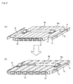
- FIG. 2 (a) is a perspective view that shows a state in which the interval between each of suction members 61a is made shortest; and Fig. 2 (b) is a perspective view that shows a state in which the interval between each of suction members 61a is made longest.
- the suction members 61b are omitted from Figs. 2(a) and 2(b) .
- through holes 75 which penetrate each suction member 61a in the horizontal direction, are formed at two positions of each of the seven suction members 61a.
- two supporting shafts 71 are inserted through all the through holes 75 at the two positions in a manner so as to penetrate the seven suction members 61a.
- the two ends of each of the two supporting shafts 71 are secured to two plate-shaped supporting shaft coupling pates 72 so that the seven suction members 61a are combined into one set, and allowed to function like a single big plate with its width being changed within a predetermined range.
- nail-shaped hooking portions 73 are formed on the two ends of each suction member 61a, and with adjacent two of the hooking portions 73 being formed into one set, a binding ring 74 is hooked on them for each set.
- binding ring 74 that has been hooked on each of the sets, their movable ranges of all the adjacent suction members 61a are determined.
- the two end portions of a driving means 66 to be used for adjusting the intervals are secured to the upper faces of the suctionmembers 61a locatedon the two ends among the seven suction members 61a placed side by side so that the intervals of the suction members 61a can be adjusted by this driving means 66.
- the suction members 61a are mutually made in contact with one another completely; in contrast, when the length of the driving means 66 is made longest, the interval between each of the mutual suction members 61a is made longest within the expandable range of the binding ring 74.
- the mutual intervals between each of the suction members 61a are determined in two states, that is, the longest length and the shortest length adjusted by the driving means 66. In this case, by adjusting the expandable range of the binding ring 74, the intervals between each of the mutual suction members 61a can be adjusted.
- the suction members 61a can be expanded at equal intervals within a range in which the binding ring 74 can be extended, regardless of the length of the driving means 66.
- the intervals between the mutual suction members 61a are extended and shrunk by the extending and shrinking operations of the driving means 66.
- the binding ring 74 is hooked on the hooking portions 73 of the adjacent suction members 61a, and since the adjacent suction members 61a are biased by the same force in the mutually approaching directions by the elastic force of the binding ring 74, the suction members 61a are expanded in a manner so as to have mutually equal intervals therebetween. Therefore, within the expandable range of the binding ring 74, the suction members 61a can be mutually extended with equal intervals in a desired state of the driving means 66 having the length between the shortest length and the longest length.
- constituent material for the binding ring 74 examples thereof include: metals such as aluminum, stainless steel, copper, iron and nickel; rubbers such as silicone rubber, natural rubber, synthetic rubber and fluororubber; and resins such as PS resin, ABS resin, POM resin, PC resin, PP resin, PE resin, PPE resin and PBT resin.
- metals such as aluminum, stainless steel, copper, iron and nickel
- rubbers such as silicone rubber, natural rubber, synthetic rubber and fluororubber
- resins such as PS resin, ABS resin, POM resin, PC resin, PP resin, PE resin, PPE resin and PBT resin.
- the binding ring has been explained as the mechanism for adjusting the mutual intervals between each of the suction members 61a; however, not limited to this, a spring may be interposed between the adjacent suction members 61a so as to carry out the adjustments, or a cylindrical member, which is flexible and constituted by cylinders having different diameters that are fitted to each other, may be interposed so as to carry out the adjustments. In this manner, any desired elastic member may be used as long as the mutual intervals between each of the suction members 61a can be adjusted.
- the transporting table 30 is arranged as any desired transporting mechanism, such as a conveyor like a belt conveyor and a chain conveyor and a cart that travels on rails.
- the degreasing jig 40 comprises a molded body placing plate 41 and a mat 42, and each ceramic molded body 100 is mounted on the degreasing jig 40 through the mat 42 made from carbon fibers and the like.
- the transporting table 30 transports the degreasing jig in a direction indicated by an arrow in Fig. 1 , and after ceramic molded bodies 100 have been mounted thereon, the degreasing jig 40 is transported to a degreasing furnace (not shown).
- the plurality of ceramic molded bodies 100 are simultaneously placed on the degreasing jig 40 by the molded body moving mechanism 20 to have predetermined intervals therebetween.
- the interval between each of the ceramic molded bodies is not generally determined because they are dependent on the size of the ceramic molded bodies, the degreasing temperature, the degreasing time and the like.
- the degreasing process progresses excessively, while when the interval is too narrow, the degreasing process becomes insufficient.
- the resulting degreased body tends to have variations (deviations) in the strength.
- a sequence of processes in which honeycomb molded bodies are placed on the degreasing jig 40 First, when ceramic molded bodies 100, obtained through the preceding processes, are transported by a conveyor 31, these are collected in a molded body receiving unit 80. As shown in Fig. 1 , in the molded body receiving unit 80, the ceramic molded bodies 100 are positioned in a manner so as to be made in contact with one another.
- the suction mechanism 60 having seven sets in which each of sets is constituted by the suction member 61a and the suction plate 61b is lowered so that the side face (upper face in the drawing) of each ceramic molded body 100 is made in contact with each suction plate 61b. Since the spring is interposed between the suction member 61a and the suction plate 61b, it is possible to alleviate an impact upon contacting. At this time, the length of the driving means 66, which adjusts the interval between each of the suction members 61a is maintained in the shortest state so that each suction plate 61b is made in contact with the side face of each ceramic molded body. Then, an air suction process is carried out by activating a suction device, not shown, so that the ceramic molded body 100 is suction-held on the suction plate 61b through the suction holes formed in the suction plate 61b.
- the suction mechanism 60 is raised to a predetermined position by the elevating mechanism 67, and the arm 50 is shifted in the horizontal direction above the degreasing jig 40 by the arm moving mechanism.
- the driving means 66 is activated so that the intervals of the seven suction members 61a are adjusted to predetermined intervals suitable for the degreasing process of the ceramic molded bodies 100.
- the intervals between each of the ceramic molded bodies 100 are made equal to one another.
- the predetermined interval suitable for the degreasing process may be properly changed and determined depending on the kind and the number of the ceramic molded bodies 100.
- the elevating mechanism 67 is activated to lower the suction mechanism 60.
- the descending of suction mechanism 60 is stopped when the ceramic molded bodies 100 come into contact with the mats 42, and the suction operation of the suction device is then stopped so that the ceramic molded bodies 100 are simultaneously mounted on the degreasing jig 40 through the mats 42. Since the mats 42 are made from carbon fibers and the like, the ceramic molded bodies 100 can be simultaneously placed on the degreasing jig 40 without causing damage thereto, when the ceramic molded bodies 100 are mounted on the degreasing jig 40.
- the ceramic molded bodies 100 are placed on the degreasing jig 40 to have intervals suitable for the degreasing process therebetween.
- the transporting table 30 is operated in a direction indicated by the arrow so that the degreasing jig 40 is transported to the degreasing furnace.
- the carry-in operation into the degreasing furnace of the ceramic molded bodies by the use of the degreasing furnace carry-in apparatus of the present invention is completed.
- a new degreasing jig is transported to the position of the transporting table 30 by a table 32 so as to successively mount ceramic molded bodies thereon.
- the layout direction of the ceramic molded bodies 100 at the time when they are transported by the conveyor 31 and the layout direction of the ceramic molded bodies 100 mounted on the degreasing jig 40 are made the same.
- the arm 50 can be rotated, and, for example, after having been rotated by 90°, the ceramic molded bodies 100 may be placed on the degreasing jig 40.
- the rotation angle can be altered on demand.
- the suction face of each ceramic molded body 100 on which the suction mechanism 60 works is desirably not an end face of the ceramic molded body 100, but as a side face thereof.
- the ceramic molded body 100 prior to the degreasing process is soft; therefore, when the suction plate 61b is made in contact with the end face to carry out a suction process, the end face might be deformed or damaged.
- the suction face of each ceramic molded body 100 on which the suction mechanism 60 works is not an end face of the ceramic molded body 100, but a side face thereof, it is possible to carry out the moving operation efficiently without causing deformations, damages and the like to the end face.
- the side face has a wider area than the end face so that the suction-holding operation is easily carried out, and since, in an attempt to suction-hold its end face, air is continuously sucked through cells, it is difficult to carry out the suction-holding operation.
- the arm 50 includes the suction mechanism 60 in which seven sets of suction members 61a and suction plates 61b having suction holes at two positions, are placed side by side; however, the number of the sets of the suction members 61a and suction plates 61b is not limited to seven, and the number thereof may be set at a desired number of 2 sets or more. However, in an attempt to lift a number of ceramic molded bodies 100 at one time andeffectivelyrearrange efficiently at predetermined intervals therebetween, the number is desirably set at 3 to 10.
- the suction force of the arm including the suction mechanism to each ceramic molded body is desirably 0.4 to 2.0 kPa.
- the suction force is less than 0.4 kPa, the suction force is too weak to suction-hold and lift the ceramic molded body; in contrast, when the suction force exceeds 2.0 kPa, the strength of the ceramic molded body might fail to resist the force, resulting in damages thereto.
- the suction force used for suction-holding the ceramic molded body can be properly altered depending on the weight and shape of the ceramic molded body to be suction-held, and for example, in the case where the suction face of the ceramic molded body is a plane and the weight thereof is 210 g, it is desirably in the range of 0.7 to 2.0 kPa.
- the molded body moving mechanism desirably includes a cushioning member at a contact portion to the ceramic molded body. Since the ceramic molded body is in a state obtained by molding a ceramic material, and optionally drying the obtained molded body, it is soft and easily deformed. Therefore, when the molded body moving mechanism includes the cushioning member at the contact portion to the ceramic molded body, it becomes possible to effectively prevent damage, deformation and the like to the ceramic molded body at the time of contacting or carrying out a suction process.
- the cushioning member not particularly limited as long as it has a cushioning function, examples of material thereof include: urethane resin, polyethylene, polypropylene, polystyrene, rubber, epoxy resin and the like.
- urethane resin is desirably used.
- the cushioning member is made of urethane resin, it becomes possible to effectively suppress an impact occurring upon contact between the suction plate and the ceramic molded body, and consequently to prevent damage or deformation to the ceramic molded body.
- the cushioning member made from any of these materials, may be a dense material or a foamed material.
- the entire portion of the cushioning member may be made from the above-mentioned materials, or may have a structure in which a sheet-shaped member made from the above-mentioned materials is sticked onto a base member made from metal, resin or a ceramic material.
- the attaching position of the cushioning member to the suction plate 61b desirably covers the entire contact face to the ceramic molded body (except for the portion of each suction hole).
- a porous cushioningmember maybe used, and in this case, the cushioningmembermaybe attached to the entire contact face including the suction holes.
- the method for manufacturing a honeycomb structured body in accordance with the present invention is a method for manufacturing a honeycomb structured body, comprising: forming a pillar-shaped honeycomb molded body having a plurality of cells longitudinally placed in parallel with one another with a partition wall therebetween by molding a ceramic raw material, degreasing the honeycomb molded body by carrying the honeycomb molded body into a degreasing furnace by using a degreasing furnace carry-in apparatus; and firing the degreased honeycomb molded body so that a honeycomb structured body comprising a honeycomb fired body is manufactured, wherein the degreasing furnace carry-in apparatus comprises: a molded body moving mechanism capable of moving a plurality of honeycomb molded bodies simultaneously; and a transporting table that transports a degreasing jig for mounting the ceramic molded bodies thereon to a degreasing furnace, and the method
- honeycomb structured body of the present invention will discuss the method for manufacturing the honeycomb structured body of the present invention successively in the order of processes.
- the following description will exemplify manufacturing processes of a honeycomb structured body in which the honeycomb structured body, which is mainly composed of silicon carbide as a constituent material, is formed by using powder of silicon carbide serving as a ceramic material.
- constituent materials for the honeycomb structured body is not intended to be limited to silicon carbide, and, other examples thereof include: nitride ceramic materials, such as aluminum nitride, silicon nitride, boron nitride and titanium nitride, carbide ceramic materials, such as zirconium carbide, titanium carbide, tantalum carbide and tungsten carbide, and oxide ceramic materials, such as alumina, zirconia, cordierite, mullite, and aluminum titanate, and the like.
- non-oxide ceramic materials are desirably used, and in particular, silicon carbide is more desirably used. Silicon carbide is used because of its superior heat resistant property, mechanical strength, thermal conductivity and the like.
- materials such as a silicon-containing ceramic material formed by blending metal silicon in the above-mentioned ceramic material and a ceramic material that is combined by silicon or a silicate compound, may also be used as the constituentmaterials, and among these, a material in which metal silicon is blended in silicon carbide (silicon-containing silicon carbide) is desirably used.
- inorganic powder serving as a ceramic material such as silicon carbide powders having different average particle sizes, and an organic binder are dry-mixed to prepare mixed powder, and a liquid-state plasticizer, a lubricant and water are mixed to prepare a mixed liquid, and the mixed powder and the mixed liquid are mixed by using a wet-mixing device so that a wet mixture for use in manufacturing a molded body is prepared.
- particle size of silicon carbide powder although not particularly limited, those which are less susceptible to shrinkage in the succeeding firing process are desirably used, and for example, mixed powder, prepared by combining 100 parts by weight of powder having an average particle size from 0.3 to 50 ⁇ m with 5 to 65 parts by weight of powder having an average particle size from 0.1 to 1.0 ⁇ m, is desirably used.
- mixed powder prepared by combining 100 parts by weight of powder having an average particle size from 0.3 to 50 ⁇ m with 5 to 65 parts by weight of powder having an average particle size from 0.1 to 1.0 ⁇ m.
- the firing temperature it is necessary to adjust the firing temperature, and the pore diameter can be adjusted by adjusting the particle size of the inorganic powder.
- organic binder examples thereof include: methyl cellulose, carboxymethyl cellulose, hydroxyethyl cellulose, polyethylene glycol and the like. Among these, methyl cellulose is desirably used.
- the blending amount of the above-mentioned binder is desirably 1 to 10 parts by weight with respect to 100 parts by weight of the inorganic powder.
- plasticizer not particularly limited, for example, glycerin and the like may be used.
- lubricant not particularly limited, for example, polyoxyalkylene-based compounds, such as polyoxyethylene alkyl ether and polyoxypropylene alkyl ether, may be used.
- specific examples of the lubricant include: polyoxyethylene monobutyl ether and polyoxypropylene monobutyl ether.
- the plasticizer and the lubricant are not necessarily contained in the mixed material powder depending on cases.
- a dispersant medium may be used, and with respect to the dispersant solution, examples thereof include: water, an organic solvent such as benzene, and alcohol such as methanol, and the like.
- a molding auxiliary may be added to the wet mixture.
- examples thereof include: ethylene glycol, dextrin, fatty acid, fatty acid soap, polyalcohol and the like.
- a pore forming agent such as balloons that are fine hollow spheres composed of oxide-based ceramics, spherical acrylic particles and graphite, may be added to the above-mentioned wet mixture, if necessary.
- balloons not particularly limited, for example, alumina balloons, glass micro-balloons, shirasuballoons, fly ash balloons (FAballoons), mullite balloons and the like may be used.
- alumina balloons are desirably used.
- the temperature thereof is desirably 28°C or less.
- the organic binder tends to be gelated.
- the rate of organic components in the wet mixture is desirably set to 10% by weight or less, and the content of moisture is desirably 8.0 to 20.0% by weight.
- the prepared wet mixture is then transported, and carried in a molding machine. After the wet mixture transported by the transporting apparatus has been carried in the extrusion-molding machine, it is extrusion-molded into a honeycomb molded body having a predetermined shape. Next, the resulting honeycomb molded body is dried by using a drying apparatus, such as a microwave drying apparatus, a hot-air drying apparatus, a dielectric drying apparatus, a reduced-pressure drying apparatus, a vacuum drying apparatus and a frozen drying apparatus, to prepare a dried honeycomb molded body.
- a drying apparatus such as a microwave drying apparatus, a hot-air drying apparatus, a dielectric drying apparatus, a reduced-pressure drying apparatus, a vacuum drying apparatus and a frozen drying apparatus, to prepare a dried honeycomb molded body.
- a cutting process is carried out on the resulting honeycomb molded body by using a cutting apparatus so that the two ends thereof are cut to prepare a honeycomb molded body having a predetermined length.
- a predetermined amount of plug material paste that forms plugs is filled into ends at the outlet side of a group of the inlet side cells and ends at the inlet side of a group of the outlet side cells, if necessary, so that predetermined cells are sealed.
- a sealing mask is made in contact with an end face (that is, cut face after the cutting process) of the honeycomb molded body, and the plug material paste is filled only into the cells that need to be plugged.
- plug material paste although not particularly limited, those plug material pastes that allow the plugs manufactured through post processes to have a porosity in a range from 30 to 75% are desirably used, and, for example, the same material as that of the wet mixture may be used.
- the above-mentioned filling process of the plug material paste may be carried out on demand, and in the case where the plug material paste is filled, for example, the honeycomb structured body obtained through the post processes can be desirably used as a honeycomb filter, while in the case where the plugmaterial paste is not filled, for example, the honeycomb structured body obtained through the post processes can be desirably used as a catalyst supporting member.
- the honeycomb molded body is transported to a degreasing furnace by using a degreasing furnace carry-in apparatus.
- the degreasing furnace carry-in apparatus of the present invention is desirably used as a degreasing furnace carry-in apparatus to be used in the method for manufacturing a honeycomb structured body of the present invention.
- the detailed structure of the degreasing furnace carry-in apparatus has already been explained; therefore, the description thereof is omitted.
- the molded body moving mechanism comprises an arm including a suction mechanism capable of simultaneously suction-holding a plurality of honeycomb molded bodies. Since the side faces of the honeycomb molded bodies are suction-heldbythe suction mechanism, thepluralityof honeycomb molded bodies can be simultaneously placed on the degreasing jig without causing any damages to the end faces. Moreover, since thepluralityof honeycombmoldedbodies are simultaneously suction-held and placed, all the honeycomb molded bodies that have been placed can be maintained almost in the same state, and a firing process can be carried out uniformly on the honeycomb molded body.
- the arm including the suction mechanism desirably has a suction force of 0.4 to 2.0 kPa for each of the ceramic molded bodies.
- the honeycomb molded body prepared by drying a honeycomb molded body after the extrusion-molding process, has a certain degree of strength; however, since the strength is smaller than that of the honeycomb fired body that has been gone through a firing process, the honeycomb molded body is easily deformed so that, in order to prevent the suction-held honeycomb molded bodies from dropping while also preventing damages and the like to the honeycomb molded body due to the suction process, the honeycomb molded bodies are desirably suction-held by a suction force within the above-mentioned range.
- the molded body moving mechanism desirably includes a cushioning member at a contact portion with each of the honeycomb molded bodies.
- the cushioning member is desirably made of urethane.
- the interval between each of the honeycomb molded bodies is desirably 3 to 10 mm.
- the above-mentioned interval is less than 3 mm, it is difficult to allow the degreasing process to progress, and in particular, adjacent honeycomb molded bodies are mutually susceptible to influences from moisture and gases that are generated upon degreasing the honeycomb molded bodies; consequently, it becomes difficult to carry out a uniform degreasing process.
- the suction mechanism that includes a driving means used for adjusting the interval of the suction members needs to have a large size to cause an increase in the running costs as well as in the installation space in the entire device, thereby failing to effectively utilize the space inside the degreasing furnace.
- the above-mentioned firing process is desirably carried out in a state that the degreased honeycomb molded bodies are placed on the degreasing jig.
- the honeycomb molded bodies are fired while they are still placed on the degreasing jig, it becomes possible to eliminate the necessity of providing a process and an apparatus used for re-placing the honeycomb molded bodies onto a jig for a firing process in a separate manner, and consequently to improve the efficiency of the entire manufacturing processes of a honeycomb structured body.
- the degreasing jig is desirably made from a material that is resistant to the firing process, and for example, a carbon material and the like may be used.
- the honeycomb molded bodies are carried in a degreasing furnace by using the degreasing furnace carry-in apparatus, and degreased under predetermined conditions (for example, when each honeycomb molded body has a size of 34 mm ⁇ 34 mm ⁇ 15 to 40 mm, the degreasing process is carried out at 200 to 500°C for 2 to 4 hours, with an interval between each of the honeycomb molded bodies being set at 5 to 8 mm) .
- honeycomb molded bodies which are still placed on the degreasing jig used for the degreasing process are fired (for example, at 1400 to 2300°C) so that a honeycomb fired body which is made of a single fired body as a whole, which has a plurality of cells longitudinally placed in parallel with one another with a cell wall therebetween, and in which either one of the ends of each cell is plugged (see Fig. 4 ) can be manufactured.
- a sealing material paste to form a sealing material layer is appliedonto a side face of the honeycomb fired body with a uniform thickness to form a sealing material paste layer, and a process of laminating another honeycomb fired body on this sealing material paste layer is successively repeated so that an aggregate of honeycomb fired bodies having a predetermined size is manufactured.
- examples thereof include a material comprising an inorganic binder, an organic binder, and inorganic fibers and/or inorganic particles and the like.
- the inorganic binder for example, silica sol, alumina sol and the like may be used. Each of these may be used alone or two or more kinds of these may be used in combination.
- silica sol is desirably used.
- organic binder examples thereof include polyvinyl alcohol, methyl cellulose, ethyl cellulose, carboxymethyl cellulose and the like. Each of these may be used alone or two or more kinds of these may be used in combination.
- organic binders carboxymethyl cellulose is desirably used.
- examples thereof include ceramic fibers, such as silica-alumina, mullite, alumina, silica and the like. Each of these may be used alone or two or more kinds of these may be used in combination.
- alumina fibers are desirably used.
- examples thereof include carbides, nitrides and the like, and specific examples include inorganic powder or the like made from silicon carbide, silicon nitride and boron nitride. Each of these may be used alone, or two or more kinds of these may be used in combination.
- silicon carbide having superior thermal conductivity is desirably used.
- a pore forming agent such as balloons that are fine hollow spheres composed of an oxide-based ceramic material, spherical acrylic particles and graphite, may be added to the above-mentioned sealing material paste, if necessary.
- balloons not particularly limited, for example, alumina balloons, glass micro-balloons, shirasu balloons, flyashballoons (FAballoons) and mullite balloons and the like may be used.
- alumina balloons are desirably used.
- this aggregate of honeycomb fired bodies is heated so that the sealingmaterial paste layers are dried and solidified to form sealing material layers (adhesive layers).
- a cutting process is carried out on the aggregate of honeycomb fired bodies in which a plurality of honeycomb fired bodies have been bonded to one another by interposing sealing material layers (adhesive layers) by using a diamond cutter or the like so that a cylindrical honeycomb block is manufactured.
- a sealing material layer is formed on the periphery of the honeycomb block by using the above-mentioned sealing material paste so that a honeycomb structured body in which a sealing material layer (coat layer) is formed on the periphery of a cylindrical honeycomb block having a structure in which a plurality of honeycomb fired bodies are bound to one another by interposing sealing material layers (adhesive layers) is manufactured.
- a catalyst is supported on the honeycomb structured body on demand.
- the supporting process of the catalyst may be carried out on the honeycomb fired bodies prior to being formed into an aggregate.
- an alumina film having a high specific surface area is desirably formed on the surface of the honeycomb structured body, and a co-catalyst and a catalyst such as platinum are applied onto the surface of the alumina film.
- the method for forming the alumina film on the surface of the honeycomb structured body for example, a method in which the honeycomb structured body is impregnated with a solution of a metal compound containing aluminum such as Al(NO 3 ) 3 and then heated, and a method in which the honeycomb structuredbody is impregnated with a solution containing alumina powder and then heated, are proposed.
- a method for applying a co-catalyst to the alumina film for example, a method in which the honeycomb structured body is impregnated with a solution of a metal compound containing a rare-earth element, such as Ce(NO 3 ) 3 , and then heated is proposed.
- a method for applying a catalyst to the alumina film for example, a method in which the honeycomb structured body is impregnated with a solution of dinitro diammine platinum nitric acid ([Pt(NH 3 ) 2 (NO 2 ) 2 ]HNO 3 , platinum concentration: 4.53% by weight) and then heated is proposed.
- a catalyst may be applied through a method in which after the catalyst has been preliminarily applied to alumina particles, the honeycomb structured body is impregnated with a solution containing the alumina powder bearing the catalyst applied thereto, and then heated.
- the honeycomb structured body manufactured through the above-mentioned method for manufacturing a honeycomb structured body is an aggregated honeycomb structured body in which a plurality of honeycomb fired bodies are bound to one another by interposing sealing material layers (adhesive layers); however, the honeycomb structured body to be manufactured by the manufacturing method of the present invention may be an integral honeycomb structured body in which a pillar-shaped honeycomb block is constituted by one honeycomb fired body.
- the main constituent material for the integral honeycomb structured body cordierite and aluminum titanate are desirably used.
- a honeycomb molded body is formed by using the same method as the manufacturing method for an aggregated honeycomb structured body except that the size of a honeycomb molded body to be molded through the extrusion-molding process is greater than that of the aggregated honeycomb structured body.
- the honeycomb molded body is dried by using a drying apparatus, such as a microwave drying apparatus, a hot-air drying apparatus, a dielectric drying apparatus, a reduced-pressure drying apparatus, a vacuum drying apparatus and a frozen drying apparatus.
- a cutting process is carried out on the dried honeycomb molded body so that the two end portions thereof are cut.
- a predetermined amount of plug material paste that forms plugs is filled into ends at the outlet side of a group of the inlet side cells and ends at the inlet side of a group of the outlet side cells so that predetermined cells are sealed.
- the degreasing and firing processes are carried out to manufacture a honeycomb block, and by forming a sealing material layer (coat layer), if necessary, an integral honeycomb structured body can be manufactured.
- a catalyst may be supported on the integral honeycomb structured body by using the above-mentioned method in the same manner.
- a honeycomb structured body of the present invention In the method for manufacturing a honeycomb structured body of the present invention as explained above, it is possible to manufacture a honeycomb structured body by using highly efficient operations. Moreover, in the case where a honeycomb structured body is manufactured through the above-mentioned method, since, upon carrying the honeycomb molded body into a degreasing furnace, the plurality of honeycomb molded bodies are simultaneously placed on a degreasing jig, thereby carrying out a degreasing process under almost the same conditions, it becomes possible to efficiently achieve a shortened process time, uniform quality and the like. Moreover, since after the degreasing process, a firing process can be carried out continuously, the sequence of working processes can be formed into a streamline form so that a further efficient operation can be achieved.
- the method for manufacturing a honeycomb structured body of the present invention makes it possible to improve the efficiency of the entire manufacturing processes.
- the above description has mainly discussed a honeycomb filter used for collecting (purifying) particulates in exhaust gases as the honeycomb structured body; however, the above-mentioned honeycomb structured body can also be desirably used as a catalyst supporting member (honeycomb catalyst) that purifies (converts) exhaust gases.
- Example 1 Powder of ⁇ -type silicon carbide having an average particle size of 10 ⁇ m (250 kg), powder of ⁇ -type silicon carbide having an average particle size of 0.5 ⁇ m (100 kg) and an organic binder (methyl cellulose) (20 kg) were mixed to prepare mixed powder. Next, separately, a lubricant (UNILUB, made by NOF Corp.) (12 kg), a plasticizer (glycerin) (5 kg) and water (65 kg) were mixed to prepare a liquid mixture, and this liquid mixture and the mixed powder were mixed by using a wet-type mixing machine so that a wet mixture was prepared. The moisture content of the wet mixture thus prepared was 14% by weight.
- a lubricant UNILUB, made by NOF Corp.
- glycerin plasticizer
- water 65 kg
- this wet mixture was transported to an extrusion-molding machine by using a transporting apparatus, and charged into a material carry-in port of an extrusion-molding machine.
- the moisture content of the wet mixture immediately before the carry-in process into the extrusion-molding machine was 13.5% by weight.
- the wet mixture was then extrusion-molded into a molded body having a shape (without sealing of cells) as shown in Figs. 4(a) and 4(b) .
- a plug material paste having the same composition as the wet mixture was filled into predetermined cells.
- the honeycomb molded body to which the plug material paste had been filled was again dried by using a drying apparatus, and the honeycomb molded body that had been dried was then carried in a degreasing furnace by using a degreasing furnace carry-in apparatus shown in Fig. 1 .
- the degreasing furnace carry-in apparatus used in this case included a cushioning member made of urethane.
- the dried honeycomb molded bodies, transported by a conveyer, were placed in a state where they were made in contact with one another, on a molded body receiving unit, and a suction mechanism was then lowered so that a suction plate having the cushioning member made of urethane was made in contact with the honeycomb molded bodies.
- the suction device was operated so that each of honeycomb molded bodies was suction-held by a suction force of 1.2 kPa.
- the weight of each of honeycomb molded bodies was 210 g.
- the arm was shifted above the degreasing jig by an arm moving means.
- the interval between each of the honeycomb molded bodies was widened to 6.0 mm by using a driving means.
- the suctionmechanism was lowered until the honeycomb molded bodies had been made in contact with the degreasing jig, and the honeycomb molded bodies were then released from the suction state by stopping the driving operation of the suction device so that the honeycomb molded bodies were mounted on the degreasing jig.
- a transporting table was activated so that the degreasing jig on which the honeycomb molded bodies were mounted was carried in the degreasing furnace.
- honeycomb molded bodies carried in the degreasing furnace, were degreased at 400°C, and the degreasing jig on which the honeycomb molded bodies were mounted was carried in a firing furnace, and firingwas carried out at 2200°C in a normal-pressure argon atmosphere for 3 hours, to manufacture honeycomb fired bodies, each of which was a silicon carbide sintered body and had a porosity of 40%, an average pore diameter of 12.5 ⁇ m, a size of 34.3 mm ⁇ 34.3 mm ⁇ 250 mm, the number of cells (cell density) of 46.5/cm 2 and a thickness of each cell wall of 0.20 mm.
- Example 2 Honeycomb fired bodies were manufactured by the same processes as Example 1, except that the suction force to each of the honeycomb molded bodies was set to a value shown in Table 1.
- Example 5 Honeycomb fired bodies were manufactured by the same processes as Example 1, except that the honeycomb molded bodies were suction-held by using the suction plate without the cushioning members.
- Example 1 Interval between each of honeycomb molded bodies (mm) Suction force (kPa) Cushioning member Surface state
- Example 1 6.0 1.2 Present ⁇
- Example 2 6.0 0.7 Present ⁇
- Example 3 6.0 1.7 Present ⁇
- Example 4 6.0 2.5 Present ⁇
- Example 5 6.0 1.2 Not present ⁇
- honeycomb fired bodies manufactured in Examples 1 to 3 were free from deformations and damages, and had a good surface state.
- Example 4 the suction force to each of the honeycomb molded bodies was set at 2.5 kPa during the manufacturing process. Thus, a suction force exceeding the endurance strength was imposed on the side face.
- Example 5 since the suction plate did not include cushioning members, an excessive impact was applied to the side face when the suction plate and the honeycomb molded bodies were made in contact with each other.
- Example 6 to 20 The same processes as Example 1 were carried out to manufacture honeycomb fired bodies except for the following points.
- the average pore diameter a cube having 1 cm in each side was cut out from each of the honeycomb fired bodies to prepare a sample, and the fine-pore distribution was measured in a range of the fine-pore diameter from 0.2 to 500 ⁇ m, by using a fine-pore distribution measuring device (AutoPore III9405, made by Shimadzu Corp.) in which a mercury injection method is adopted, in compliance with JIS R 1655, and the average fine-pore diameter at this time was calculated as (4 V/A) so that the average pore diameter was calculated.
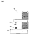
- the breaking strength was evaluated by using the following method.
- a honeycomb fired body was placed on a measuring table 202 of the texture analyzer 200 shown in Fig 5 with its side face facing up, and a probe 201 was then lowered onto the side face forming an upper face at a speed of 0.5 mm/s so that the compression load at the time of breaking was measured.
- a probe made of stainless steel
- the results thereof are shown in Table 2, Figs. 6(a) and 6(b).
- Fig. 6(a) is a graph showing the relationship between interval and average pore diameter in the honeycomb structured bodies according to Examples 6 to 20
- Fig. 6(b) is a graph showing the relationship between interval and breaking load in the honeycomb structured bodies according to Examples 6 to 20.
- Example 6 18 ⁇ 18 2.5 1.2 Present 7.4 18.6
- Example 7 18 ⁇ 18 3.0 1.2 Present 10.2 24.0
- Example 8 18 ⁇ 18 6.0 1.2 Present 10.5 25.3
- Example 9 18 ⁇ 18 10.0 1.2 Present 10.6 22.9
- Example 10 18 ⁇ 18 15.0 1.2 Present 10.5 19.1
- Example 11 34 ⁇ 34 2.5 1.2 Present 8.1 18.0
- Example 12 34 ⁇ 34 3.0 1.2 Present 10.2 24.2
- Example 13 34 ⁇ 34 6.0 1.2 Present 10.4 25.5
- Example 14 34 ⁇ 34 10.0 1.2 Present 10.9 23.4
- Example 15 34 ⁇ 34 15.0 1.2 Present 11.0 19.5
- Example 16 50 ⁇ 50 2.5 1.2 Present 7.9 17.6
- Example 17 50 ⁇ 50 3.0 1.2 Present 10.0 23.8
- Example 18 50 ⁇ 50 6.0 1.2 Present 10.4 24.8
- Example 19 50 ⁇ 50 10.0
- Figs. 6 (a) and 6 (b) in any of the honeycomb fired bodies manufactured in Examples 6 to 20, good results were obtained with respect to the average pore diameter and breaking load.
- Examples 7 to 9, Examples 12 to 14, as well as Examples 17 to 19 which are referred to as group I of Examples
- good results were obtained with respect to both of the average pore diameter and breaking load, regardless of the cross-sectional dimension of each of the honeycomb molded bodies; thus, it was clearly found that honeycomb fired bodies having predetermined quality were manufactured.
- honeycomb fired bodies according to Examples 6, 11 and 16 which are referred to as group II of Examples
- they were applicable as products without causing problems they had an average pore diameter of a value of about 2 to 3 ⁇ m smaller than that of group I, and also had a breaking load of a value of about 4 to 6 N smaller than that of group I.
- group II since the degreasing process was carried out with an interval between each of honeycomb molded bodies being set at 2.5 mm, it became difficult to allow the degreasing process to progress and it was not possible to carry out the degreasing process uniformly due to influences from moisture and gases generated from the honeycomb molded bodies upon degreasing.
- honeycomb fired bodies manufactured in Examples 10, 15 and 20 which are referred to as group III of Examples
- good values were obtained with respect to the average pore diameter.
- the resulting value was lowered in comparison with group I, although it was in a range that allows the honeycomb fired bodies to be sufficiently applied as products. The reason for this is explained as follows.
- group III differently from group I, since the degreasing process was carried out with an interval between each of honeycomb molded bodies being set at 15.0 mm, the degreasing process progressed excessively, making it difficult to carry out the degreasing process uniformly.
- the honeycomb molded bodies were carried in a degreasing furnace by using the degreasing furnace carry-in apparatus of the present invention, and then fired so that it became possible to manufacture honeycomb fired bodies that have superior properties in the average pore diameter and the breaking load.
- the results of Examples according to groups I to III indicate that the interval for placing between each of the placed honeycomb molded bodies during the degreasing process formed a main factor.
- the placing interval was desirably 3.0 to 10.0 mm.
Landscapes
- Engineering & Computer Science (AREA)
- Mechanical Engineering (AREA)
- General Engineering & Computer Science (AREA)
- Ceramic Engineering (AREA)
- Chemical & Material Sciences (AREA)
- Devices For Post-Treatments, Processing, Supply, Discharge, And Other Processes (AREA)
- Filtering Materials (AREA)
Claims (10)
- Appareil de transport pour four de dégraissage (10) comprenant :un mécanisme de déplacement de corps moulé (20) capable de déplacer simultanément une pluralité de corps moulés en céramique (100) ; etune table de transport (30) qui transporte une monture de dégraissage (40), pour monter là-dessus les corps moulés en céramique (100), vers un four de dégraissage,dans lequelledit mécanisme de déplacement de corps moulé (20) place simultanément la pluralité de corps moulés en céramique (100) sur la monture de dégraissage, chacun desdits corps moulés en céramique (100) étant placé pour avoir des intervalles prédéterminés entre ceux-ci,dans lequelledit mécanisme de déplacement de corps moulé (20) comprend un bras (50) incluant un mécanisme d'aspiration (60) capable de maintenir simultanément par aspiration la pluralité de corps moulés en céramique (100), le mécanisme d'aspiration (60) ayant des éléments d'aspiration (61a) et des plaques d'aspiration (61b) placés parallèlement les uns aux autres de façon à être en face les uns des autres dans la direction horizontale et un mécanisme pour ajuster l'intervalle entre chacun des éléments d'aspiration (61a), dans lequel le mécanisme pour ajuster l'intervalle entre chacun des éléments d'aspiration comprend :un moyen d'entraînement (66) solidement fixé aux éléments d'aspiration situés sur les deux extrémités de la pluralité d'éléments d'aspiration et pouvant être mis en oeuvre entre une longueur la plus longue et une longueur la plus courte ; etune pluralité d'éléments de liaison élastiques (74) chacun étant disposé sur des éléments d'aspiration adjacents pour déterminer des intervalles mutuels entre chacun des éléments d'aspiration lorsque la longueur du moyen d'entraînement est rendue la plus longue.
- Appareil de transport pour four de dégraissage selon la revendication 1,
dans lequel
le bras (50) incluant ledit mécanisme d'aspiration (60) a une force d'aspiration de 0,4 à 2,0 kPa pour chacun des corps moulés en céramique (100). - Appareil de transport pour four de dégraissage (10) selon l'une quelconque des revendications 1 à 2,
dans lequel
ledit mécanisme de déplacement de corps moulé (20) inclut un élément d'amortissement au niveau d'une partie de contact avec chacun desdits corps moulés en céramique (100). - Appareil de transport pour four de dégraissage (10) selon la revendication 3,
dans lequel
ledit élément d'amortissement est fait d'uréthane. - Procédé pour fabriquer un corps à structure en nid d'abeilles, comprenant :la formation d'un corps moulé en nid d'abeilles en forme de pilier ayant une pluralité de cellules placées longitudinalement parallèlement les unes aux autres avec une paroi de séparation entre celles-ci par moulage d'une matière première céramique,le dégraissage du corps moulé en nid d'abeilles en transportant le corps moulé en nid d'abeilles dans un four de dégraissage en utilisant un appareil de transport pour four de dégraissage (10) ; etla cuisson du corps moulé en nid d'abeilles dégraissé de sorte qu'un corps à structure en nid d'abeilles comprenant un corps cuit en nid d'abeilles (140) est fabriqué,dans lequelledit appareil de transport pour four de dégraissage (10) comprend :un mécanisme de déplacement de corps moulé (20) capable de déplacer simultanément une pluralité de corps moulés en nid d'abeilles (100) ; etune table de transport (30) qui transporte une monture de dégraissage (40) pour monter là-dessus les corps moulés en céramique (100) vers un four de dégraissage, etledit procédé pour fabriquer un corps à structure en nid d'abeilles comprend en outre :le placement de la pluralité de corps moulés en nid d'abeilles (100) simultanément sur ladite monture de dégraissage (40) en utilisant ledit mécanisme de déplacement de corps moulé (20), chacun desdits corps moulés en nid d'abeilles (100) étant placé pour avoir des intervalles prédéterminés entre ceux-ci ; etle transport de ladite monture de dégraissage (40) en utilisant ladite table de transport (30) pour effectuer ledit dégraissage,dans lequelledit mécanisme de déplacement de corps moulé (20) comprend un bras (50) incluant un mécanisme d'aspiration (60) capable de maintenir simultanément par aspiration la pluralité de corps moulés en nid d'abeilles (100), le mécanisme d'aspiration (60) ayant des éléments d'aspiration (61a) et des plaques d'aspiration (61b) placés parallèlement les uns aux autres de façon à être en face les uns des autres dans la direction horizontale et un mécanisme pour ajuster l'intervalle entre chacun des éléments d'aspiration (61a), dans lequel le mécanisme pour ajuster l'intervalle entre chacun des éléments d'aspiration comprend :un moyen d'entraînement (66) solidement fixé aux éléments d'aspiration situés sur les deux extrémités de la pluralité d'éléments d'aspiration et pouvant être mis en oeuvre entre une longueur la plus longue et une longueur la plus courte ; etune pluralité d'éléments de liaison élastiques (74), chacun étant disposé sur des éléments d'aspiration adjacents pour déterminer des intervalles mutuels entre chacun des éléments d'aspiration quand la longueur du moyen d'entraînement est rendue la plus longue.
- Procédé pour fabriquer un corps à structure en nid d'abeilles selon la revendication 5,
dans lequel
le bras (50) incluant ledit mécanisme d'aspiration (60) a une force d'aspiration de 0,4 à 2,0 kPa pour chacun des corps moulés en nid d'abeilles (100). - Procédé pour fabriquer un corps à structure en nid d'abeilles selon l'une quelconque des revendications 5 à 6,
dans lequel
ledit mécanisme de déplacement de corps moulé (20) inclut un élément d'amortissement au niveau d'une partie de contact avec chacun desdits corps moulés en céramique (100). - Procédé pour fabriquer un corps à structure en nid d'abeilles selon la revendication 7,
dans lequel
ledit élément d'amortissement est fait d'uréthane. - Procédé pour fabriquer un corps à structure en nid d'abeilles selon l'une quelconque des revendications 5 à 8,
dans lequel
lors du placement de la pluralité de corps moulés en nid d'abeilles (100) sur la monture de dégraissage (40), un intervalle entre chacun des corps moulés en nid d'abeilles (100) est de 3 à 10 mm. - Procédé pour fabriquer un corps à structure en nid d'abeilles selon l'une quelconque des revendications 5 à 9,
dans lequel
ladite cuisson est effectuée dans un état où lesdits corps moulés dégraissés en nid d'abeilles sont placés sur ladite monture de dégraissage (40).
Priority Applications (1)
| Application Number | Priority Date | Filing Date | Title |
|---|---|---|---|
| PL07002219T PL1832535T3 (pl) | 2006-03-08 | 2007-02-01 | Urządzenie przenoszące do pieca do odtłuszczania oraz sposób wytwarzania korpusu o strukturze plastra miodu |
Applications Claiming Priority (1)
| Application Number | Priority Date | Filing Date | Title |
|---|---|---|---|
| PCT/JP2006/304508 WO2007102216A1 (fr) | 2006-03-08 | 2006-03-08 | appareil pour introduction dans un four à dégraissage et processus de fabrication de structure alvéolaire |
Publications (2)
| Publication Number | Publication Date |
|---|---|
| EP1832535A1 EP1832535A1 (fr) | 2007-09-12 |
| EP1832535B1 true EP1832535B1 (fr) | 2010-10-13 |
Family
ID=38174613
Family Applications (1)
| Application Number | Title | Priority Date | Filing Date |
|---|---|---|---|
| EP07002219A Active EP1832535B1 (fr) | 2006-03-08 | 2007-02-01 | Appareil de transport de four dégraissant et procédé de fabrication d'un corps structuré en nid d'abeille |
Country Status (4)
| Country | Link |
|---|---|
| US (1) | US7632452B2 (fr) |
| EP (1) | EP1832535B1 (fr) |
| PL (1) | PL1832535T3 (fr) |
| WO (1) | WO2007102216A1 (fr) |
Families Citing this family (82)
| Publication number | Priority date | Publication date | Assignee | Title |
|---|---|---|---|---|
| JPWO2003067041A1 (ja) * | 2002-02-05 | 2005-06-02 | イビデン株式会社 | 排気ガス浄化用ハニカムフィルタ、接着剤、塗布材、及び、排気ガス浄化用ハニカムフィルタの製造方法 |
| EP1604725B1 (fr) * | 2002-03-15 | 2007-09-26 | Ibiden Co., Ltd. | Filtre en céramique pour la purification de gaz d'échappement |
| DE60317174T3 (de) | 2002-03-22 | 2013-01-17 | Ibiden Co., Ltd. | Herstellungsverfahren eines wabenfilters zur reinigung von abgas |
| US7648547B2 (en) | 2002-04-10 | 2010-01-19 | Ibiden Co., Ltd. | Honeycomb filter for clarifying exhaust gas |
| JP4386830B2 (ja) * | 2002-04-11 | 2009-12-16 | イビデン株式会社 | 排気ガス浄化用ハニカムフィルタ |
| US20060051556A1 (en) * | 2003-09-12 | 2006-03-09 | Ibiden Co., Ltd. | Sintered ceramic compact and ceramic filter |
| US7981475B2 (en) * | 2003-11-05 | 2011-07-19 | Ibiden Co., Ltd. | Manufacturing method of honeycomb structural body, and sealing material |
| JPWO2005108328A1 (ja) | 2004-05-06 | 2008-03-21 | イビデン株式会社 | ハニカム構造体及びその製造方法 |
| JP4592695B2 (ja) * | 2004-05-18 | 2010-12-01 | イビデン株式会社 | ハニカム構造体及び排気ガス浄化装置 |
| ATE405804T1 (de) * | 2004-07-01 | 2008-09-15 | Ibiden Co Ltd | Verfahren zur herstellung von porösen keramischen körpern |
| EP1662219B1 (fr) * | 2004-08-04 | 2008-09-10 | Ibiden Co., Ltd. | Four de cuisson et procede pour fabriquer un element poreux ceramique a l'aide du dit four |
| WO2006013932A1 (fr) * | 2004-08-06 | 2006-02-09 | Ibiden Co., Ltd. | Four de frittage et procédé de fabrication de corps fritté de céramique poreuse utilisant ce four |
| JPWO2006022131A1 (ja) * | 2004-08-25 | 2008-05-08 | イビデン株式会社 | 焼成炉及びその焼成炉を用いた多孔質セラミック焼成体の製造方法 |
| JP5142529B2 (ja) * | 2004-09-30 | 2013-02-13 | イビデン株式会社 | ハニカム構造体 |
| WO2006082938A1 (fr) * | 2005-02-04 | 2006-08-10 | Ibiden Co., Ltd. | Structure en nid d’abeille ceramique et procede de fabrication de celle-ci |
| JP2006223983A (ja) * | 2005-02-17 | 2006-08-31 | Ibiden Co Ltd | ハニカム構造体 |
| JP4812316B2 (ja) * | 2005-03-16 | 2011-11-09 | イビデン株式会社 | ハニカム構造体 |
| KR100810476B1 (ko) * | 2005-03-28 | 2008-03-07 | 이비덴 가부시키가이샤 | 허니컴 구조체 |
| WO2006103786A1 (fr) * | 2005-03-28 | 2006-10-05 | Ibiden Co., Ltd. | Structure en nid d’abeille et materiau d’etancheite |
| KR100822246B1 (ko) * | 2005-04-07 | 2008-04-16 | 이비덴 가부시키가이샤 | 허니컴 구조체 |
| CN100434398C (zh) * | 2005-04-28 | 2008-11-19 | 揖斐电株式会社 | 蜂窝结构体 |
| ATE526252T1 (de) * | 2005-06-06 | 2011-10-15 | Ibiden Co Ltd | Verwendung eines verpackungsmaterials und verfahren für den transport eines wabenförmig strukturierten körpers |
| CN1954137B (zh) * | 2005-07-21 | 2011-12-21 | 揖斐电株式会社 | 蜂窝结构体以及废气净化装置 |
| EP1832565A4 (fr) * | 2005-08-03 | 2007-10-17 | Ibiden Co Ltd | Gabarit pour la cuisson de carbure de silicium et procédé de production d un corps poreux de carbure de silicium |
| KR100884518B1 (ko) * | 2005-08-26 | 2009-02-18 | 이비덴 가부시키가이샤 | 허니컴 구조체 및 그 제조 방법 |
| WO2007039991A1 (fr) * | 2005-10-05 | 2007-04-12 | Ibiden Co., Ltd. | Filière de moulage par extrusion et processus de fabrication d’élément céramique poreux |
| WO2007058007A1 (fr) | 2005-11-18 | 2007-05-24 | Ibiden Co., Ltd. | Structure en nid d'abeilles |
| WO2007058006A1 (fr) * | 2005-11-18 | 2007-05-24 | Ibiden Co., Ltd. | Structure en nid d'abeilles |
| CN101312809A (zh) * | 2005-12-26 | 2008-11-26 | 揖斐电株式会社 | 蜂窝结构体的制造方法 |
| WO2007074528A1 (fr) * | 2005-12-27 | 2007-07-05 | Ibiden Co., Ltd. | Gabarit de dégraissage, procédé de dégraissage de céramique moulée, et processus de fabrication de structure alvéolaire |
| CN101309883B (zh) * | 2006-01-27 | 2012-12-26 | 揖斐电株式会社 | 蜂窝结构体及其制造方法 |
| WO2007086143A1 (fr) * | 2006-01-30 | 2007-08-02 | Ibiden Co., Ltd. | Procede d'inspection d'un corps de structure en nid d'abeilles et procede de production d'un corps de structure en nid d'abeilles |
| WO2007094075A1 (fr) * | 2006-02-17 | 2007-08-23 | Ibiden Co., Ltd. | Unité d'assemblage et unité de desassemblage de dispositif de fixation pour le séchage, appareil de circulation dudit dispositif, procédé de séchage de moulage en céramique, et procédé de production de structure en nid d'abeille |
| WO2007097056A1 (fr) * | 2006-02-23 | 2007-08-30 | Ibiden Co., Ltd. | Structure en nid d'abeille et purificateur de gaz de rejet |
| WO2007097004A1 (fr) * | 2006-02-24 | 2007-08-30 | Ibiden Co., Ltd. | Appareil et procede de melangeage a l'etat humide et procede de production de structures en nid d'abeille |
| WO2007097000A1 (fr) * | 2006-02-24 | 2007-08-30 | Ibiden Co., Ltd. | Dispositif de scellage des extremites pour corps en nid d'abeille, procede d'application de materiau de scellement en pate et procede de production d'un corps a structure en nid d'abeille |
| ATE404835T1 (de) * | 2006-02-28 | 2008-08-15 | Ibiden Co Ltd | Trageelement für trocknung, trocknungsverfahren eines presslings mit wabenstruktur, und verfahren zur herstellung eines wabenkörpers. |
| WO2007102216A1 (fr) | 2006-03-08 | 2007-09-13 | Ibiden Co., Ltd. | appareil pour introduction dans un four à dégraissage et processus de fabrication de structure alvéolaire |
| WO2007102217A1 (fr) * | 2006-03-08 | 2007-09-13 | Ibiden Co., Ltd. | refroidisseur de corps cuit, four de cuisson, procédé de refroidissement de corps cuit céramique, et processus de fabrication de structure alvéolaire |
| JP4863904B2 (ja) * | 2006-03-31 | 2012-01-25 | イビデン株式会社 | ハニカム構造体およびその製造方法 |
| WO2007116529A1 (fr) | 2006-04-11 | 2007-10-18 | Ibiden Co., Ltd. | appareil de découpe d'un article moulé, procédé de découpe d'un article moulé en céramique et processus pour produire une structure en nid d'abeille |
| WO2007122680A1 (fr) * | 2006-04-13 | 2007-11-01 | Ibiden Co., Ltd. | Machine de moulage par extrusion, procédé de moulage par extrusion et procédé destiné à produire une structure en nid d'abeille |
| WO2007122707A1 (fr) * | 2006-04-19 | 2007-11-01 | Ibiden Co., Ltd. | Procédé permettant de produire une structure en nid d'abeille |
| WO2007122715A1 (fr) * | 2006-04-20 | 2007-11-01 | Ibiden Co., Ltd. | Méthode d'inspection d'un corps cuit en nid d'abeilles et procédé de fabrication d'une structure en nid d'abeilles |
| WO2007122716A1 (fr) * | 2006-04-20 | 2007-11-01 | Ibiden Co., Ltd. | Dispositif de transport et procédé de fabrication d'une structure en nid d'abeilles |
| WO2007129391A1 (fr) * | 2006-05-01 | 2007-11-15 | Ibiden Co., Ltd. | Unité de montage de gabarit de cuisson, unité de démontage de gabarit de cuisson, appareil de circulation, procédé de moulage de céramique de cuisson, et processus de production de structure de nid d'abeille |
| WO2007129399A1 (fr) * | 2006-05-08 | 2007-11-15 | Ibiden Co., Ltd. | PROCÉDÉ DE FABRICATION D'UNE STRUCTURE EN NID D'ABEILLES, MACHINE DE RÉCePTION DE MOULAGES EN NID D'ABEILLES ET MACHINE DE DÉMONTAGE DE MOULAGES EN NID D'ABEILLES |
| WO2007132530A1 (fr) * | 2006-05-17 | 2007-11-22 | Ibiden Co., Ltd. | Appareil de finition de face d'extrémité pour moulage alvéolaire, procédé d'obturation de moulage alvéolaire et processus de fabrication de structure alvéolaire |
| WO2007138701A1 (fr) * | 2006-05-31 | 2007-12-06 | Ibiden Co., Ltd. | Dispositif de maintien et procédé de production de structure alvéolaire |
| DE602006005804D1 (de) * | 2006-07-07 | 2009-04-30 | Ibiden Co Ltd | Apparat und Verfahren zur Bearbeitung der Endfläche eines Wabenkörpers und Verfahren zur Herstellung eines Wabenkörpers |
| WO2008032391A1 (fr) * | 2006-09-14 | 2008-03-20 | Ibiden Co., Ltd. | Procédé de production d'une structure en nid d'abeille et composition de matière première pour nid d'abeille calciné |
| WO2008032390A1 (fr) * | 2006-09-14 | 2008-03-20 | Ibiden Co., Ltd. | Procédé de production d'une structure en nid d'abeille |
| EP1900709B1 (fr) * | 2006-09-14 | 2010-06-09 | Ibiden Co., Ltd. | Procédé pour la préparation de structures en nid d'abeille et composition pour structures en nid d'abeille frittées |
| WO2008047404A1 (fr) * | 2006-10-16 | 2008-04-24 | Ibiden Co., Ltd. | Support de montage pour structure alvéolaire et dispositif d'inspection pour structure alvéolaire |
| JP5084517B2 (ja) * | 2007-01-26 | 2012-11-28 | イビデン株式会社 | 外周層形成装置 |
| WO2008099450A1 (fr) * | 2007-02-09 | 2008-08-21 | Ibiden Co., Ltd. | Structure en nid d'abeilles et appareil de traitement de gaz d'échappement |
| WO2008099454A1 (fr) * | 2007-02-09 | 2008-08-21 | Ibiden Co., Ltd. | Structure en nid d'abeilles et appareil de traitement de gaz d'échappement |
| WO2008120385A1 (fr) * | 2007-03-29 | 2008-10-09 | Ibiden Co., Ltd. | Structure de nid d'abeilles, son procédé de fabrication, appareil de purification de gaz d'échappement et procédé de fabrication de l'appareil |
| EP1982966B1 (fr) * | 2007-03-29 | 2011-11-09 | Ibiden Co., Ltd. | Structure en nid d'abeille et son procédé de production |
| WO2008126320A1 (fr) * | 2007-03-30 | 2008-10-23 | Ibiden Co., Ltd. | Procédé de fabrication d'une structure en nid d'abeilles |
| WO2008121263A1 (fr) * | 2007-03-30 | 2008-10-09 | Corning Incorporated | Procédé et applicateur pour séchage électromagnétique sélectif de mélange de formation de céramique |
| WO2008139581A1 (fr) * | 2007-05-09 | 2008-11-20 | Ibiden Co., Ltd. | Procédé de production d'une matière première pour la cuisson de carbure de silicium et procédé de production d'une structure en nid d'abeille |
| WO2008149435A1 (fr) * | 2007-06-06 | 2008-12-11 | Ibiden Co., Ltd. | Gabarit de cuisson et procédé de fabrication d'une structure en nid d'abeilles |
| WO2008155856A1 (fr) | 2007-06-21 | 2008-12-24 | Ibiden Co., Ltd. | Structure en nid d'abeille et son procédé de production |
| WO2009057213A1 (fr) * | 2007-10-31 | 2009-05-07 | Ibiden Co., Ltd. | Emballage pour structure en nid d'abeilles et procédé de transport de structure en nid d'abeilles |
| WO2009066388A1 (fr) * | 2007-11-21 | 2009-05-28 | Ibiden Co., Ltd. | Structure en nid-d'abeilles et son procédé de production |
| WO2009101683A1 (fr) | 2008-02-13 | 2009-08-20 | Ibiden Co., Ltd. | Processus de production d'une structure en nid d'abeilles |
| WO2009101682A1 (fr) | 2008-02-13 | 2009-08-20 | Ibiden Co., Ltd. | Structure en nid d'abeilles, appareil de purification de gaz d'échappement et processus de production d'une structure en nid d'abeilles |
| WO2009107230A1 (fr) * | 2008-02-29 | 2009-09-03 | イビデン株式会社 | Matière d'étanchéité pour structure en nid d'abeilles, structure en nid d'abeilles et procédé pour produire une structure en nid d'abeilles |
| WO2009118814A1 (fr) * | 2008-03-24 | 2009-10-01 | イビデン株式会社 | Filtre en nid d'abeilles |
| WO2009118813A1 (fr) * | 2008-03-24 | 2009-10-01 | イビデン株式会社 | Structure en nid d'abeille et son procédé de production |
| WO2009118862A1 (fr) * | 2008-03-27 | 2009-10-01 | イビデン株式会社 | Procédé de production d'une structure en nid d'abeilles |
| DE102011106214A1 (de) * | 2011-06-07 | 2012-12-13 | Brötje-Automation GmbH | Endeffektor |
| CN102700935A (zh) * | 2012-05-16 | 2012-10-03 | 启东市罗源光伏设备有限公司 | 太阳能组件移动机械手臂 |
| US9908718B2 (en) | 2012-10-19 | 2018-03-06 | Dow Global Technologies Llc | Device, system, and method for lifting and moving formable and/or collapsible parts |
| CN103612416B (zh) * | 2013-10-22 | 2017-10-13 | 杭州东博自动化科技有限公司 | 自动取坯设备的自动取坯装置 |
| CN103569872B (zh) * | 2013-11-25 | 2016-03-23 | 环球石材(福建)有限公司 | 石材规格板排板装置 |
| JP6264942B2 (ja) * | 2014-02-28 | 2018-01-24 | 株式会社村田製作所 | 脱脂処理炉 |
| DE102015009177A1 (de) | 2015-07-09 | 2017-01-12 | Broetje-Automation Gmbh | Verfahren zum Herstellen eines Faser-Metall-Laminatbauteils eines Flugzeugs |
| CN105947632B (zh) * | 2016-06-28 | 2018-05-29 | 广西北流市智宇陶瓷自动化设备有限公司 | 陶瓷坯体垫板放置机构 |
| US10369706B2 (en) * | 2017-08-09 | 2019-08-06 | The Boeing Company | End effectors carrying plies of limp material for shaping by a mandrel |
| JP7115844B2 (ja) * | 2017-12-13 | 2022-08-09 | 日本碍子株式会社 | 柱状ハニカム構造体の移載装置 |
Citations (1)
| Publication number | Priority date | Publication date | Assignee | Title |
|---|---|---|---|---|
| JPH02273131A (ja) * | 1989-04-13 | 1990-11-07 | Takeda Chem Ind Ltd | ミシマサイコ属植物の製造方法 |
Family Cites Families (105)
| Publication number | Priority date | Publication date | Assignee | Title |
|---|---|---|---|---|
| US3033382A (en) * | 1958-02-10 | 1962-05-08 | Jack D Noble | Plate-lifting device |
| IT1161391B (it) * | 1978-03-30 | 1987-03-18 | Longinotti Enrico | Perfezionamento nelle apparecchiature di movimentazione di mattonelle o simili con l'usilio di vassoi su cui le mattonelle sono deposte per la stagionatura |
| DE3023072A1 (de) * | 1980-06-20 | 1982-01-07 | C. Keller GmbH u. Co KG, 4530 Ibbenbüren | Verfahren und vorrichtung zum umsetzen keramischer formlinge, insbesondere strangdachziegel |
| DE3425165A1 (de) | 1984-07-07 | 1986-01-16 | Hans Lingl Anlagenbau Und Verfahrenstechnik Gmbh & Co Kg, 7910 Neu-Ulm | Verfahren zum ueberfuehren von keramischen formlingen auf traglatten und vorrichtung zur durchfuehrung des verfahrens |
| JPS6175711A (ja) * | 1984-09-20 | 1986-04-18 | Fuji Seisakusho:Kk | 段状コンベヤ装置 |
| JPS61214944A (ja) | 1985-03-20 | 1986-09-24 | Ngk Insulators Ltd | ハニカム構造製品の移載装置 |
| JPH0760068B2 (ja) * | 1990-03-16 | 1995-06-28 | 日本碍子株式会社 | 焼成台車への瓦の積み込み方法 |
| JPH06137769A (ja) * | 1992-10-28 | 1994-05-20 | Harima Ceramic Co Ltd | 精錬容器等への煉瓦積付け装置 |
| JP3715341B2 (ja) * | 1995-01-09 | 2005-11-09 | 碧南特殊機械株式会社 | 平板瓦の焼成システムにおける白地又は焼成品の積込・降ろし方法及び積込・降ろし装置 |
| EP1382442B1 (fr) * | 1996-01-12 | 2013-04-24 | Ibiden Co., Ltd. | Filtre pour purifier de gaz d'échappement |
| JPH09255436A (ja) * | 1996-03-19 | 1997-09-30 | Sony Corp | 成形品の製造方法 |
| JPH1026480A (ja) * | 1996-07-11 | 1998-01-27 | Sumitomo Kinzoku Electro Device:Kk | 超小物セラミック成形品の焼成用セッターへの詰め込み方法及びその装置 |
| JPH10167801A (ja) * | 1996-12-11 | 1998-06-23 | Takasago Ind Co Ltd | 平板瓦の焼成方法及びその方法に用いる平板瓦の積載具 |
| NL1009652C2 (nl) * | 1998-07-14 | 2000-01-18 | Ebm Techniek Bv | Inrichting voor het aangrijpen op producten. |
| KR100446205B1 (ko) * | 1999-09-29 | 2004-08-31 | 이비덴 가부시키가이샤 | 하니콤 필터 및 세라믹 필터 집합체, 그리고 이를 갖는 배기가스 정화장치 |
| US6439631B1 (en) * | 2000-03-03 | 2002-08-27 | Micron Technology, Inc. | Variable-pitch pick and place device |
| JPWO2002096827A1 (ja) * | 2001-05-31 | 2004-09-09 | イビデン株式会社 | 多孔質セラミック焼結体及びその製造方法、ディーゼルパティキュレートフィルタ |
| JP4266103B2 (ja) * | 2001-12-07 | 2009-05-20 | 日本碍子株式会社 | 多孔質セラミック体の製造方法 |
| EP1479882B2 (fr) | 2002-02-05 | 2012-08-22 | Ibiden Co., Ltd. | Filtre a nids d'abeille pour la decontamination des gaz d'echappement |
| JPWO2003067041A1 (ja) * | 2002-02-05 | 2005-06-02 | イビデン株式会社 | 排気ガス浄化用ハニカムフィルタ、接着剤、塗布材、及び、排気ガス浄化用ハニカムフィルタの製造方法 |
| ES2300563T3 (es) * | 2002-03-04 | 2008-06-16 | Ibiden Co., Ltd. | Filtro de tipo para purificacion de gas de escape y aparato de purificacion de gas de escape. |
| EP1604725B1 (fr) * | 2002-03-15 | 2007-09-26 | Ibiden Co., Ltd. | Filtre en céramique pour la purification de gaz d'échappement |
| DE60317174T3 (de) * | 2002-03-22 | 2013-01-17 | Ibiden Co., Ltd. | Herstellungsverfahren eines wabenfilters zur reinigung von abgas |
| WO2003084640A1 (fr) * | 2002-04-09 | 2003-10-16 | Ibiden Co., Ltd. | Filtre en nid d'abeille pour la clarification d'un gaz d'echappement |
| US7648547B2 (en) * | 2002-04-10 | 2010-01-19 | Ibiden Co., Ltd. | Honeycomb filter for clarifying exhaust gas |
| JP4386830B2 (ja) * | 2002-04-11 | 2009-12-16 | イビデン株式会社 | 排気ガス浄化用ハニカムフィルタ |
| KR100632161B1 (ko) * | 2003-02-28 | 2006-10-11 | 이비덴 가부시키가이샤 | 세라믹 하니컴 구조체 |
| JP2004292197A (ja) * | 2003-03-26 | 2004-10-21 | Ngk Insulators Ltd | ハニカム構造体の製造方法 |
| US20060073970A1 (en) * | 2003-05-06 | 2006-04-06 | Ibiden Co., Ltd. | Honeycomb structure body |
| US20060051556A1 (en) * | 2003-09-12 | 2006-03-09 | Ibiden Co., Ltd. | Sintered ceramic compact and ceramic filter |
| US7981475B2 (en) * | 2003-11-05 | 2011-07-19 | Ibiden Co., Ltd. | Manufacturing method of honeycomb structural body, and sealing material |
| PL1790623T3 (pl) * | 2003-11-12 | 2009-11-30 | Ibiden Co Ltd | Sposób wytwarzania struktury ceramicznej |
| US7387829B2 (en) * | 2004-01-13 | 2008-06-17 | Ibiden Co., Ltd. | Honeycomb structure, porous body, pore forming material for the porous body, and methods for manufacturing the pore forming material, the porous body and the honeycomb structure |
| KR100637298B1 (ko) * | 2004-04-05 | 2006-10-24 | 이비덴 가부시키가이샤 | 벌집형 구조체, 벌집형 구조체의 제조 방법 및 배기 가스정화 장치 |
| JPWO2005108328A1 (ja) * | 2004-05-06 | 2008-03-21 | イビデン株式会社 | ハニカム構造体及びその製造方法 |
| JP4592695B2 (ja) * | 2004-05-18 | 2010-12-01 | イビデン株式会社 | ハニカム構造体及び排気ガス浄化装置 |
| ATE405804T1 (de) * | 2004-07-01 | 2008-09-15 | Ibiden Co Ltd | Verfahren zur herstellung von porösen keramischen körpern |
| PL1710523T3 (pl) * | 2004-08-04 | 2008-09-30 | Ibiden Co Ltd | Piec do wypalania o działaniu ciągłym i sposób wytwarzania porowatego elementu ceramicznego za jego pomocą |
| EP1818639A4 (fr) * | 2004-08-04 | 2007-08-29 | Ibiden Co Ltd | Four de cuisson et procédé de fabrication d'un article cuit céramique poreux utilisant le four de cuisson |
| EP1662219B1 (fr) * | 2004-08-04 | 2008-09-10 | Ibiden Co., Ltd. | Four de cuisson et procede pour fabriquer un element poreux ceramique a l'aide du dit four |
| WO2006013932A1 (fr) * | 2004-08-06 | 2006-02-09 | Ibiden Co., Ltd. | Four de frittage et procédé de fabrication de corps fritté de céramique poreuse utilisant ce four |
| DE602005003538T2 (de) * | 2004-08-10 | 2008-10-23 | Ibiden Co., Ltd., Ogaki | Brennofen und verfahren zur herstellung von keramischen teilen mit diesem brennofen |
| JPWO2006022131A1 (ja) * | 2004-08-25 | 2008-05-08 | イビデン株式会社 | 焼成炉及びその焼成炉を用いた多孔質セラミック焼成体の製造方法 |
| WO2006035823A1 (fr) * | 2004-09-30 | 2006-04-06 | Ibiden Co., Ltd. | Structure alvéolaire |
| JP5142529B2 (ja) * | 2004-09-30 | 2013-02-13 | イビデン株式会社 | ハニカム構造体 |
| DE602005015610D1 (de) * | 2004-10-12 | 2009-09-03 | Ibiden Co Ltd | Keramische wabenstruktur |
| WO2006057344A1 (fr) * | 2004-11-26 | 2006-06-01 | Ibiden Co., Ltd. | Structure en nid d'abeille |
| PL1707251T3 (pl) * | 2004-12-28 | 2013-03-29 | Ibiden Co Ltd | Filtr i zespół filtra |
| WO2006082938A1 (fr) * | 2005-02-04 | 2006-08-10 | Ibiden Co., Ltd. | Structure en nid d’abeille ceramique et procede de fabrication de celle-ci |
| JP4880581B2 (ja) * | 2005-02-04 | 2012-02-22 | イビデン株式会社 | セラミックハニカム構造体 |
| JP2006223983A (ja) * | 2005-02-17 | 2006-08-31 | Ibiden Co Ltd | ハニカム構造体 |
| JP4812316B2 (ja) * | 2005-03-16 | 2011-11-09 | イビデン株式会社 | ハニカム構造体 |
| KR100810476B1 (ko) * | 2005-03-28 | 2008-03-07 | 이비덴 가부시키가이샤 | 허니컴 구조체 |
| WO2006103786A1 (fr) * | 2005-03-28 | 2006-10-05 | Ibiden Co., Ltd. | Structure en nid d’abeille et materiau d’etancheite |
| JPWO2006112052A1 (ja) * | 2005-03-30 | 2008-11-27 | イビデン株式会社 | 炭化珪素含有粒子、炭化珪素質焼結体を製造する方法、炭化珪素質焼結体、及びフィルター |
| KR100822246B1 (ko) * | 2005-04-07 | 2008-04-16 | 이비덴 가부시키가이샤 | 허니컴 구조체 |
| JP2006289237A (ja) * | 2005-04-08 | 2006-10-26 | Ibiden Co Ltd | ハニカム構造体 |
| CN100434398C (zh) * | 2005-04-28 | 2008-11-19 | 揖斐电株式会社 | 蜂窝结构体 |
| WO2006126278A1 (fr) * | 2005-05-27 | 2006-11-30 | Ibiden Co., Ltd. | Corps de structure alveolaire |
| CN1954137B (zh) * | 2005-07-21 | 2011-12-21 | 揖斐电株式会社 | 蜂窝结构体以及废气净化装置 |
| KR100884518B1 (ko) * | 2005-08-26 | 2009-02-18 | 이비덴 가부시키가이샤 | 허니컴 구조체 및 그 제조 방법 |
| CN101146589B (zh) * | 2005-09-28 | 2010-11-24 | 揖斐电株式会社 | 蜂窝式过滤器 |
| WO2007039991A1 (fr) * | 2005-10-05 | 2007-04-12 | Ibiden Co., Ltd. | Filière de moulage par extrusion et processus de fabrication d’élément céramique poreux |
| JPWO2007043245A1 (ja) | 2005-10-12 | 2009-04-16 | イビデン株式会社 | ハニカムユニット及びハニカム構造体 |
| WO2007058007A1 (fr) * | 2005-11-18 | 2007-05-24 | Ibiden Co., Ltd. | Structure en nid d'abeilles |
| WO2007058006A1 (fr) * | 2005-11-18 | 2007-05-24 | Ibiden Co., Ltd. | Structure en nid d'abeilles |
| CN101312809A (zh) * | 2005-12-26 | 2008-11-26 | 揖斐电株式会社 | 蜂窝结构体的制造方法 |
| US20070187651A1 (en) * | 2005-12-26 | 2007-08-16 | Kazuya Naruse | Method for mixing powder, agitation apparatus, and method for manufacturing honeycomb structured body |
| CN101312895A (zh) * | 2005-12-27 | 2008-11-26 | 揖斐电株式会社 | 搬运装置和蜂窝结构体的制造方法 |
| WO2007074528A1 (fr) * | 2005-12-27 | 2007-07-05 | Ibiden Co., Ltd. | Gabarit de dégraissage, procédé de dégraissage de céramique moulée, et processus de fabrication de structure alvéolaire |
| CN101309883B (zh) * | 2006-01-27 | 2012-12-26 | 揖斐电株式会社 | 蜂窝结构体及其制造方法 |
| WO2007086143A1 (fr) * | 2006-01-30 | 2007-08-02 | Ibiden Co., Ltd. | Procede d'inspection d'un corps de structure en nid d'abeilles et procede de production d'un corps de structure en nid d'abeilles |
| WO2007094075A1 (fr) * | 2006-02-17 | 2007-08-23 | Ibiden Co., Ltd. | Unité d'assemblage et unité de desassemblage de dispositif de fixation pour le séchage, appareil de circulation dudit dispositif, procédé de séchage de moulage en céramique, et procédé de production de structure en nid d'abeille |
| WO2007097056A1 (fr) * | 2006-02-23 | 2007-08-30 | Ibiden Co., Ltd. | Structure en nid d'abeille et purificateur de gaz de rejet |
| WO2007097004A1 (fr) * | 2006-02-24 | 2007-08-30 | Ibiden Co., Ltd. | Appareil et procede de melangeage a l'etat humide et procede de production de structures en nid d'abeille |
| WO2007096986A1 (fr) * | 2006-02-24 | 2007-08-30 | Ibiden Co., Ltd. | Dispositif de chauffage de face d'extremite, procede de sechage de la face d'extremite d'un assemblage en nid d'abeille et procede de production de structures en nid d'abeille |
| WO2007097000A1 (fr) * | 2006-02-24 | 2007-08-30 | Ibiden Co., Ltd. | Dispositif de scellage des extremites pour corps en nid d'abeille, procede d'application de materiau de scellement en pate et procede de production d'un corps a structure en nid d'abeille |
| ATE551167T1 (de) * | 2006-02-28 | 2012-04-15 | Ibiden Co Ltd | Verfahren zur herstellung von einem wabenstrukturkörper |
| WO2007102217A1 (fr) * | 2006-03-08 | 2007-09-13 | Ibiden Co., Ltd. | refroidisseur de corps cuit, four de cuisson, procédé de refroidissement de corps cuit céramique, et processus de fabrication de structure alvéolaire |
| WO2007102216A1 (fr) | 2006-03-08 | 2007-09-13 | Ibiden Co., Ltd. | appareil pour introduction dans un four à dégraissage et processus de fabrication de structure alvéolaire |
| WO2007108076A1 (fr) * | 2006-03-17 | 2007-09-27 | Ibiden Co., Ltd. | Appareil de séchage, méthode de séchage d'une piece moulée céramique, et méthode de production d'une structure en nid d'abeille |
| JP4863904B2 (ja) | 2006-03-31 | 2012-01-25 | イビデン株式会社 | ハニカム構造体およびその製造方法 |
| WO2007116529A1 (fr) * | 2006-04-11 | 2007-10-18 | Ibiden Co., Ltd. | appareil de découpe d'un article moulé, procédé de découpe d'un article moulé en céramique et processus pour produire une structure en nid d'abeille |
| WO2007122680A1 (fr) * | 2006-04-13 | 2007-11-01 | Ibiden Co., Ltd. | Machine de moulage par extrusion, procédé de moulage par extrusion et procédé destiné à produire une structure en nid d'abeille |
| WO2007122707A1 (fr) * | 2006-04-19 | 2007-11-01 | Ibiden Co., Ltd. | Procédé permettant de produire une structure en nid d'abeille |
| WO2007129391A1 (fr) * | 2006-05-01 | 2007-11-15 | Ibiden Co., Ltd. | Unité de montage de gabarit de cuisson, unité de démontage de gabarit de cuisson, appareil de circulation, procédé de moulage de céramique de cuisson, et processus de production de structure de nid d'abeille |
| WO2007129399A1 (fr) * | 2006-05-08 | 2007-11-15 | Ibiden Co., Ltd. | PROCÉDÉ DE FABRICATION D'UNE STRUCTURE EN NID D'ABEILLES, MACHINE DE RÉCePTION DE MOULAGES EN NID D'ABEILLES ET MACHINE DE DÉMONTAGE DE MOULAGES EN NID D'ABEILLES |
| WO2007138701A1 (fr) * | 2006-05-31 | 2007-12-06 | Ibiden Co., Ltd. | Dispositif de maintien et procédé de production de structure alvéolaire |
| EP1880818A1 (fr) * | 2006-06-05 | 2008-01-23 | Ibiden Co., Ltd. | Méthode pour la coupe d'une structure en nid d'abeilles |
| DE602006005804D1 (de) * | 2006-07-07 | 2009-04-30 | Ibiden Co Ltd | Apparat und Verfahren zur Bearbeitung der Endfläche eines Wabenkörpers und Verfahren zur Herstellung eines Wabenkörpers |
| WO2008032391A1 (fr) * | 2006-09-14 | 2008-03-20 | Ibiden Co., Ltd. | Procédé de production d'une structure en nid d'abeille et composition de matière première pour nid d'abeille calciné |
| EP1900709B1 (fr) * | 2006-09-14 | 2010-06-09 | Ibiden Co., Ltd. | Procédé pour la préparation de structures en nid d'abeille et composition pour structures en nid d'abeille frittées |
| WO2008032390A1 (fr) * | 2006-09-14 | 2008-03-20 | Ibiden Co., Ltd. | Procédé de production d'une structure en nid d'abeille |
| WO2008047404A1 (fr) * | 2006-10-16 | 2008-04-24 | Ibiden Co., Ltd. | Support de montage pour structure alvéolaire et dispositif d'inspection pour structure alvéolaire |
| JP5084517B2 (ja) * | 2007-01-26 | 2012-11-28 | イビデン株式会社 | 外周層形成装置 |
| WO2008099454A1 (fr) * | 2007-02-09 | 2008-08-21 | Ibiden Co., Ltd. | Structure en nid d'abeilles et appareil de traitement de gaz d'échappement |
| WO2008099450A1 (fr) * | 2007-02-09 | 2008-08-21 | Ibiden Co., Ltd. | Structure en nid d'abeilles et appareil de traitement de gaz d'échappement |
| EP1982966B1 (fr) * | 2007-03-29 | 2011-11-09 | Ibiden Co., Ltd. | Structure en nid d'abeille et son procédé de production |
| WO2008120386A1 (fr) * | 2007-03-29 | 2008-10-09 | Ibiden Co., Ltd. | Structure de nid d'abeilles |
| WO2008120385A1 (fr) * | 2007-03-29 | 2008-10-09 | Ibiden Co., Ltd. | Structure de nid d'abeilles, son procédé de fabrication, appareil de purification de gaz d'échappement et procédé de fabrication de l'appareil |
| WO2008129691A1 (fr) * | 2007-03-30 | 2008-10-30 | Ibiden Co., Ltd. | Filtre en nid d'abeilles |
| WO2008126320A1 (fr) * | 2007-03-30 | 2008-10-23 | Ibiden Co., Ltd. | Procédé de fabrication d'une structure en nid d'abeilles |
| WO2008139581A1 (fr) | 2007-05-09 | 2008-11-20 | Ibiden Co., Ltd. | Procédé de production d'une matière première pour la cuisson de carbure de silicium et procédé de production d'une structure en nid d'abeille |
| WO2008149435A1 (fr) | 2007-06-06 | 2008-12-11 | Ibiden Co., Ltd. | Gabarit de cuisson et procédé de fabrication d'une structure en nid d'abeilles |
| WO2008155856A1 (fr) | 2007-06-21 | 2008-12-24 | Ibiden Co., Ltd. | Structure en nid d'abeille et son procédé de production |
-
2006
- 2006-03-08 WO PCT/JP2006/304508 patent/WO2007102216A1/fr active Application Filing
-
2007
- 2007-02-01 EP EP07002219A patent/EP1832535B1/fr active Active
- 2007-02-01 PL PL07002219T patent/PL1832535T3/pl unknown
- 2007-11-14 US US11/940,123 patent/US7632452B2/en not_active Expired - Fee Related
Patent Citations (1)
| Publication number | Priority date | Publication date | Assignee | Title |
|---|---|---|---|---|
| JPH02273131A (ja) * | 1989-04-13 | 1990-11-07 | Takeda Chem Ind Ltd | ミシマサイコ属植物の製造方法 |
Non-Patent Citations (1)
| Title |
|---|
| DATABASE WPI Section Ch Week 200270, Derwent World Patents Index; Class H06, AN 2002-652186, "Honeycomb structured filter, used for arresting particulate matter in diesel engine exhaust ga, comprises porous silicon carbide" * |
Also Published As
| Publication number | Publication date |
|---|---|
| WO2007102216A1 (fr) | 2007-09-13 |
| EP1832535A1 (fr) | 2007-09-12 |
| US20080174039A1 (en) | 2008-07-24 |
| PL1832535T3 (pl) | 2011-03-31 |
| US7632452B2 (en) | 2009-12-15 |
Similar Documents
| Publication | Publication Date | Title |
|---|---|---|
| EP1832535B1 (fr) | Appareil de transport de four dégraissant et procédé de fabrication d'un corps structuré en nid d'abeille | |
| EP1974884B1 (fr) | Procédé de fabrication d'un élément structuré en nid d'abeille | |
| US20080111274A1 (en) | Degreasing jig assembling apparatus, degreasing jig disassembling apparatus, degreasing jig circulating apparatus, method for degreasing ceramic molded body, and method for manufacturing honeycomb structured body | |
| EP1852211B1 (fr) | Appareil de montage de cuisson, appareil de désassemblage de cuisson, appareil de circulation, procédé de cuisson d'un élément moulé en céramique et procédé de fabrication d'un élément structuré en nid d'abeille | |
| EP1832827B1 (fr) | Dispositif de refroidissement, four de calcination, méthode de refroidissement et procédé de fabrication d'une structure céramique à nid d'abeille | |
| EP1825979B1 (fr) | Procédé de fabrication pour un corps structuré en nid d'abeilles | |
| EP1862424B1 (fr) | Appareil et procédé de support pour fabriquer un corps structuré en nid d'abeille | |
| EP1964655B1 (fr) | Procédé de fabrication d'un élément structuré en nid d'abeille | |
| EP1834936B1 (fr) | Procédé pour le séchage à l'extrémité d'un assemblage de corps en nid d'abeille, dispositif pour l'exécution de ce procédé et procédé pour la fabrication d'une structure en nid d'abeille | |
| EP1826517B1 (fr) | Support de séchage, procédé de séchage d'un corps moulé en nid d'abeilles, et procédé pour la fabrication d'un corps à structure en nid d'abeilles | |
| EP1900709B1 (fr) | Procédé pour la préparation de structures en nid d'abeille et composition pour structures en nid d'abeille frittées | |
| EP1975139B1 (fr) | Corps structuré en nid d'abeille | |
| EP2105183B1 (fr) | Filtre en nids d'abeilles | |
| EP1847824A2 (fr) | Procédé d'inspection d'un élément brûlé en nid d'abeilles et procédé de fabrication d'un corps structuré en nid d'abeilles | |
| EP1975138A1 (fr) | Procédé pour la fabrication d'un corps fritté en carbure de silicium poreux | |
| EP1965047B1 (fr) | Corps structuré en nid d'abeille | |
| EP1880818A1 (fr) | Méthode pour la coupe d'une structure en nid d'abeilles | |
| JP4987559B2 (ja) | 把持装置、及び、ハニカム構造体の製造方法 | |
| EP2090559B1 (fr) | Corps structuré en nid d'abeille | |
| JP2008170139A (ja) | 脱脂用治具組立装置、脱脂用治具分解装置、脱脂用治具循環装置、セラミック成形体の脱脂方法、及び、ハニカム構造体の製造方法 |
Legal Events
| Date | Code | Title | Description |
|---|---|---|---|
| PUAI | Public reference made under article 153(3) epc to a published international application that has entered the european phase |
Free format text: ORIGINAL CODE: 0009012 |
|
| 17P | Request for examination filed |
Effective date: 20070201 |
|
| AK | Designated contracting states |
Kind code of ref document: A1 Designated state(s): AT BE BG CH CY CZ DE DK EE ES FI FR GB GR HU IE IS IT LI LT LU LV MC NL PL PT RO SE SI SK TR |
|
| AX | Request for extension of the european patent |
Extension state: AL BA HR MK YU |
|
| 17Q | First examination report despatched |
Effective date: 20071227 |
|
| AKX | Designation fees paid |
Designated state(s): AT BE BG CH CY CZ DE DK EE ES FI FR GB GR HU IE IS IT LI LT LU LV MC NL PL PT RO SE SI SK TR |
|
| GRAP | Despatch of communication of intention to grant a patent |
Free format text: ORIGINAL CODE: EPIDOSNIGR1 |
|
| GRAS | Grant fee paid |
Free format text: ORIGINAL CODE: EPIDOSNIGR3 |
|
| GRAA | (expected) grant |
Free format text: ORIGINAL CODE: 0009210 |
|
| RIN1 | Information on inventor provided before grant (corrected) |
Inventor name: SAIJO, TAKAMITSU Inventor name: KASAI, KENICHIRO |
|
| AK | Designated contracting states |
Kind code of ref document: B1 Designated state(s): AT BE BG CH CY CZ DE DK EE ES FI FR GB GR HU IE IS IT LI LT LU LV MC NL PL PT RO SE SI SK TR |
|
| REG | Reference to a national code |
Ref country code: GB Ref legal event code: FG4D |
|
| REG | Reference to a national code |
Ref country code: CH Ref legal event code: EP |
|
| REG | Reference to a national code |
Ref country code: IE Ref legal event code: FG4D |
|
| REF | Corresponds to: |
Ref document number: 602007009739 Country of ref document: DE Date of ref document: 20101125 Kind code of ref document: P |
|
| REG | Reference to a national code |
Ref country code: NL Ref legal event code: VDEP Effective date: 20101013 |
|
| LTIE | Lt: invalidation of european patent or patent extension |
Effective date: 20101013 |
|
| REG | Reference to a national code |
Ref country code: PL Ref legal event code: T3 |
|
| PG25 | Lapsed in a contracting state [announced via postgrant information from national office to epo] |
Ref country code: LT Free format text: LAPSE BECAUSE OF FAILURE TO SUBMIT A TRANSLATION OF THE DESCRIPTION OR TO PAY THE FEE WITHIN THE PRESCRIBED TIME-LIMIT Effective date: 20101013 |
|
| PG25 | Lapsed in a contracting state [announced via postgrant information from national office to epo] |
Ref country code: NL Free format text: LAPSE BECAUSE OF FAILURE TO SUBMIT A TRANSLATION OF THE DESCRIPTION OR TO PAY THE FEE WITHIN THE PRESCRIBED TIME-LIMIT Effective date: 20101013 Ref country code: LV Free format text: LAPSE BECAUSE OF FAILURE TO SUBMIT A TRANSLATION OF THE DESCRIPTION OR TO PAY THE FEE WITHIN THE PRESCRIBED TIME-LIMIT Effective date: 20101013 Ref country code: PT Free format text: LAPSE BECAUSE OF FAILURE TO SUBMIT A TRANSLATION OF THE DESCRIPTION OR TO PAY THE FEE WITHIN THE PRESCRIBED TIME-LIMIT Effective date: 20110214 Ref country code: IS Free format text: LAPSE BECAUSE OF FAILURE TO SUBMIT A TRANSLATION OF THE DESCRIPTION OR TO PAY THE FEE WITHIN THE PRESCRIBED TIME-LIMIT Effective date: 20110213 Ref country code: FI Free format text: LAPSE BECAUSE OF FAILURE TO SUBMIT A TRANSLATION OF THE DESCRIPTION OR TO PAY THE FEE WITHIN THE PRESCRIBED TIME-LIMIT Effective date: 20101013 Ref country code: BG Free format text: LAPSE BECAUSE OF FAILURE TO SUBMIT A TRANSLATION OF THE DESCRIPTION OR TO PAY THE FEE WITHIN THE PRESCRIBED TIME-LIMIT Effective date: 20110113 Ref country code: AT Free format text: LAPSE BECAUSE OF FAILURE TO SUBMIT A TRANSLATION OF THE DESCRIPTION OR TO PAY THE FEE WITHIN THE PRESCRIBED TIME-LIMIT Effective date: 20101013 Ref country code: SI Free format text: LAPSE BECAUSE OF FAILURE TO SUBMIT A TRANSLATION OF THE DESCRIPTION OR TO PAY THE FEE WITHIN THE PRESCRIBED TIME-LIMIT Effective date: 20101013 Ref country code: SE Free format text: LAPSE BECAUSE OF FAILURE TO SUBMIT A TRANSLATION OF THE DESCRIPTION OR TO PAY THE FEE WITHIN THE PRESCRIBED TIME-LIMIT Effective date: 20101013 |
|
| PG25 | Lapsed in a contracting state [announced via postgrant information from national office to epo] |
Ref country code: GR Free format text: LAPSE BECAUSE OF FAILURE TO SUBMIT A TRANSLATION OF THE DESCRIPTION OR TO PAY THE FEE WITHIN THE PRESCRIBED TIME-LIMIT Effective date: 20110114 Ref country code: BE Free format text: LAPSE BECAUSE OF FAILURE TO SUBMIT A TRANSLATION OF THE DESCRIPTION OR TO PAY THE FEE WITHIN THE PRESCRIBED TIME-LIMIT Effective date: 20101013 |
|
| PG25 | Lapsed in a contracting state [announced via postgrant information from national office to epo] |
Ref country code: ES Free format text: LAPSE BECAUSE OF FAILURE TO SUBMIT A TRANSLATION OF THE DESCRIPTION OR TO PAY THE FEE WITHIN THE PRESCRIBED TIME-LIMIT Effective date: 20110124 Ref country code: EE Free format text: LAPSE BECAUSE OF FAILURE TO SUBMIT A TRANSLATION OF THE DESCRIPTION OR TO PAY THE FEE WITHIN THE PRESCRIBED TIME-LIMIT Effective date: 20101013 Ref country code: CZ Free format text: LAPSE BECAUSE OF FAILURE TO SUBMIT A TRANSLATION OF THE DESCRIPTION OR TO PAY THE FEE WITHIN THE PRESCRIBED TIME-LIMIT Effective date: 20101013 |
|
| PLBE | No opposition filed within time limit |
Free format text: ORIGINAL CODE: 0009261 |
|
| STAA | Information on the status of an ep patent application or granted ep patent |
Free format text: STATUS: NO OPPOSITION FILED WITHIN TIME LIMIT |
|
| PG25 | Lapsed in a contracting state [announced via postgrant information from national office to epo] |
Ref country code: RO Free format text: LAPSE BECAUSE OF FAILURE TO SUBMIT A TRANSLATION OF THE DESCRIPTION OR TO PAY THE FEE WITHIN THE PRESCRIBED TIME-LIMIT Effective date: 20101013 Ref country code: SK Free format text: LAPSE BECAUSE OF FAILURE TO SUBMIT A TRANSLATION OF THE DESCRIPTION OR TO PAY THE FEE WITHIN THE PRESCRIBED TIME-LIMIT Effective date: 20101013 Ref country code: DK Free format text: LAPSE BECAUSE OF FAILURE TO SUBMIT A TRANSLATION OF THE DESCRIPTION OR TO PAY THE FEE WITHIN THE PRESCRIBED TIME-LIMIT Effective date: 20101013 |
|
| 26N | No opposition filed |
Effective date: 20110714 |
|
| PG25 | Lapsed in a contracting state [announced via postgrant information from national office to epo] |
Ref country code: MC Free format text: LAPSE BECAUSE OF NON-PAYMENT OF DUE FEES Effective date: 20110228 |
|
| REG | Reference to a national code |
Ref country code: CH Ref legal event code: PL |
|
| GBPC | Gb: european patent ceased through non-payment of renewal fee |
Effective date: 20110201 |
|
| PG25 | Lapsed in a contracting state [announced via postgrant information from national office to epo] |
Ref country code: CH Free format text: LAPSE BECAUSE OF NON-PAYMENT OF DUE FEES Effective date: 20110228 Ref country code: LI Free format text: LAPSE BECAUSE OF NON-PAYMENT OF DUE FEES Effective date: 20110228 |
|
| REG | Reference to a national code |
Ref country code: DE Ref legal event code: R097 Ref document number: 602007009739 Country of ref document: DE Effective date: 20110714 |
|
| REG | Reference to a national code |
Ref country code: FR Ref legal event code: ST Effective date: 20111102 |
|
| REG | Reference to a national code |
Ref country code: IE Ref legal event code: MM4A |
|
| PG25 | Lapsed in a contracting state [announced via postgrant information from national office to epo] |
Ref country code: IT Free format text: LAPSE BECAUSE OF FAILURE TO SUBMIT A TRANSLATION OF THE DESCRIPTION OR TO PAY THE FEE WITHIN THE PRESCRIBED TIME-LIMIT Effective date: 20101013 |
|
| PG25 | Lapsed in a contracting state [announced via postgrant information from national office to epo] |
Ref country code: IE Free format text: LAPSE BECAUSE OF NON-PAYMENT OF DUE FEES Effective date: 20110201 Ref country code: FR Free format text: LAPSE BECAUSE OF NON-PAYMENT OF DUE FEES Effective date: 20110228 |
|
| PG25 | Lapsed in a contracting state [announced via postgrant information from national office to epo] |
Ref country code: GB Free format text: LAPSE BECAUSE OF NON-PAYMENT OF DUE FEES Effective date: 20110201 |
|
| PG25 | Lapsed in a contracting state [announced via postgrant information from national office to epo] |
Ref country code: CY Free format text: LAPSE BECAUSE OF FAILURE TO SUBMIT A TRANSLATION OF THE DESCRIPTION OR TO PAY THE FEE WITHIN THE PRESCRIBED TIME-LIMIT Effective date: 20101013 Ref country code: LU Free format text: LAPSE BECAUSE OF NON-PAYMENT OF DUE FEES Effective date: 20110201 |
|
| PG25 | Lapsed in a contracting state [announced via postgrant information from national office to epo] |
Ref country code: TR Free format text: LAPSE BECAUSE OF FAILURE TO SUBMIT A TRANSLATION OF THE DESCRIPTION OR TO PAY THE FEE WITHIN THE PRESCRIBED TIME-LIMIT Effective date: 20101013 |
|
| PG25 | Lapsed in a contracting state [announced via postgrant information from national office to epo] |
Ref country code: HU Free format text: LAPSE BECAUSE OF FAILURE TO SUBMIT A TRANSLATION OF THE DESCRIPTION OR TO PAY THE FEE WITHIN THE PRESCRIBED TIME-LIMIT Effective date: 20101013 |
|
| PGFP | Annual fee paid to national office [announced via postgrant information from national office to epo] |
Ref country code: PL Payment date: 20171229 Year of fee payment: 12 |
|
| PG25 | Lapsed in a contracting state [announced via postgrant information from national office to epo] |
Ref country code: PL Free format text: LAPSE BECAUSE OF NON-PAYMENT OF DUE FEES Effective date: 20190201 |
|
| PGFP | Annual fee paid to national office [announced via postgrant information from national office to epo] |
Ref country code: DE Payment date: 20231228 Year of fee payment: 18 |