EP1832402A1 - Formmaschine zum Formen von Bestandteilen aus Holz oder dergleichen in Längsrichtung, insbesondere für Bestandteile von Tür- oder Fensterrahmen - Google Patents
Formmaschine zum Formen von Bestandteilen aus Holz oder dergleichen in Längsrichtung, insbesondere für Bestandteile von Tür- oder Fensterrahmen Download PDFInfo
- Publication number
- EP1832402A1 EP1832402A1 EP07103893A EP07103893A EP1832402A1 EP 1832402 A1 EP1832402 A1 EP 1832402A1 EP 07103893 A EP07103893 A EP 07103893A EP 07103893 A EP07103893 A EP 07103893A EP 1832402 A1 EP1832402 A1 EP 1832402A1
- Authority
- EP
- European Patent Office
- Prior art keywords
- component part
- shaping machine
- insertion direction
- jaws
- shaping
- Prior art date
- Legal status (The legal status is an assumption and is not a legal conclusion. Google has not performed a legal analysis and makes no representation as to the accuracy of the status listed.)
- Granted
Links
- 239000002023 wood Substances 0.000 title claims abstract description 7
- 238000007493 shaping process Methods 0.000 title claims description 49
- 238000003780 insertion Methods 0.000 claims abstract description 20
- 230000037431 insertion Effects 0.000 claims abstract description 20
- 238000003754 machining Methods 0.000 description 3
- 238000004519 manufacturing process Methods 0.000 description 1
- 230000000284 resting effect Effects 0.000 description 1
Images

Classifications
-
- B—PERFORMING OPERATIONS; TRANSPORTING
- B27—WORKING OR PRESERVING WOOD OR SIMILAR MATERIAL; NAILING OR STAPLING MACHINES IN GENERAL
- B27F—DOVETAILED WORK; TENONS; SLOTTING MACHINES FOR WOOD OR SIMILAR MATERIAL; NAILING OR STAPLING MACHINES
- B27F1/00—Dovetailed work; Tenons; Making tongues or grooves; Groove- and- tongue jointed work; Finger- joints
- B27F1/02—Making tongues or grooves, of indefinite length
- B27F1/04—Making tongues or grooves, of indefinite length along only one edge of a board
-
- B—PERFORMING OPERATIONS; TRANSPORTING
- B27—WORKING OR PRESERVING WOOD OR SIMILAR MATERIAL; NAILING OR STAPLING MACHINES IN GENERAL
- B27M—WORKING OF WOOD NOT PROVIDED FOR IN SUBCLASSES B27B - B27L; MANUFACTURE OF SPECIFIC WOODEN ARTICLES
- B27M1/00—Working of wood not provided for in subclasses B27B - B27L, e.g. by stretching
- B27M1/08—Working of wood not provided for in subclasses B27B - B27L, e.g. by stretching by multi-step processes
Definitions
- the present invention relates to a shaping machine for longitudinally shaping component parts of wood or similar, in particular, component parts of door and window frames.
- a component part having two substantially parallel, longitudinal lateral faces is shaped longitudinally using a shaping machine comprising at least one gripping device for gripping the part; and a work unit for shaping the longitudinal lateral faces of the part.
- the gripping device normally comprises at least one bottom jaw and at least one top jaw, which receive the part in an insertion direction substantially perpendicular to the longitudinal lateral faces of the part, and are movable with respect to each other between a part gripping position and a part release position.
- the part is inserted between the jaws to rest against a stop member, which extends between the jaws to position the part correctly in the insertion direction and permit shaping of the longitudinal lateral face projecting from the jaws.
- shaping the second longitudinal lateral face means moving the jaws into the release position, extracting the part from the jaws, rotating the part 180°, reinserting the part between the jaws, and moving the jaws back into the gripping position.
- the above sequence is fairly complicated and time-consuming, requires the assistance of an operator, and may impair correct, accurate shaping of the two faces.
- a shaping machine comprising two gripping devices of the type described, and on which the part is gripped between the jaws of one gripping device to shape one longitudinal lateral face, and is transferred to the jaws of the other gripping device to shape the other longitudinal lateral face.
- two gripping devices obviously makes the shaping machine fairly complicated, bulky, and expensive.
- Another drawback common to both the above known types of shaping machine is that, once inserted between the jaws of the gripping device, the component part projects outwards of the jaws by a portion whose width, measured parallel to the insertion direction, varies alongside a variation in the width of the component part, also measured parallel to the insertion direction, and may, over and above a given width, impair the stability of the part as it is being shaped.
- a shaping machine for longitudinally shaping component parts of wood or similar, in particular, component parts of door and window frames, as claimed in the accompanying Claims.
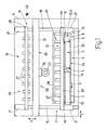
- Number 1 in Figure 1 indicates as a whole a shaping machine for longitudinally shaping component parts 2 of wood or similar, in particular, component parts 2 of door and window frames.
- each component part 2 is in the form of an elongated, substantially rectangular-section parallelepiped, and has two parallel major lateral faces 3; two parallel minor lateral faces 4 perpendicular to faces 3; and two parallel minor lateral faces 5 perpendicular to faces 3 and 4.
- Machine 1 comprises an elongated bed 6 extending in a horizontal direction 7 and supporting a conveyor device 8, which extends in direction 7 and comprises a belt 9 looped about two pulleys (not shown), one of which is powered, and which are mounted to rotate about respective longitudinal axes 10 parallel to a horizontal direction 11 crosswise to direction 7.
- Belt 9 has a substantially horizontal top conveying branch 12, on which component parts 2 are positioned "flat", i.e. with one face 3 resting on branch 12, with faces 4 perpendicular to direction 11, and with faces 5 perpendicular to direction 7.
- Component parts 2 are fed successively by device 8 along a path P, parallel to direction 7, to a transfer station 13 having a number of (in the example shown, two) stop members 14 arranged successively along path P.
- Each member 14 extends crosswise to direction 7 to position component 2 correctly in direction 7, and is movable between a work position ( Figure 1), in which member 14 projects onto path P, and a rest position (not shown), in which member 14 clears path P.
- Bed 6 is fitted with two guides 15, which extend parallel to direction 11 and support a grip-and-carry unit 16 comprising two grip-and-carry devices 17, 18, of which device 17 is located between device 8 and device 18, and is connected to device 8 at station 13.
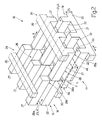
- each device 17, 18 comprises a comb-like bottom jaw 19 extending over bed 6 in direction 7, and comprising a supporting bar 20, which extends in direction 7, is fitted in sliding manner to guides 15 by two skids 21, and is moved linearly in direction 11 along guides 15 by a known actuating device not shown.
- Bar 20 has a number of parallel teeth 22, each of which projects from bar 20 in direction 11, and is bounded at the top by a flat horizontal surface 23 coplanar with surfaces 23 of the other teeth 22 and with top conveying branch 12 of belt 9 to define a supporting surface A for component parts 2.
- Each device 17, 18 also comprises a top jaw 24, which extends over bed 6 in direction 7, is aligned with relative jaw 19 in a vertical direction 25 perpendicular to directions 7 and 11, and comprises a supporting bar 26 connected in known manner to bar 20 to move in direction 25 between a gripping position and a release position respectively gripping and releasing at least one component part 2.
- Jaw 24 is comb-shaped, and has a number of parallel teeth 27, each of which projects from bar 26 in direction 11, and is aligned in direction 25 with a corresponding tooth 22 of relative bottom jaw 19.
- teeth 22, 27 of jaws 19, 24 of device 17 are offset in direction 7 with respect to teeth 22, 27 of jaws 19, 24 of device 18.
- Jaws 19, 24 of each device 17, 18 define between them a channel 28 for insertion of component parts 2 in direction 11.
- Channel 28 has no stop members for arresting component parts 2 in direction 11, so that component parts 2 can be inserted through the channel from one end to the other and along its whole length in direction 11.
- Shaping machine 1 also comprises a work unit 29 comprising a fixed bridge crane 30, which in turn comprises two uprights (not shown), which extend upwards from bed in direction 25, are located on opposite sides of guides 15 in direction 7, and are fitted with a horizontal cross member 31 extending over guides 15 in direction 7.
- a work unit 29 comprising a fixed bridge crane 30, which in turn comprises two uprights (not shown), which extend upwards from bed in direction 25, are located on opposite sides of guides 15 in direction 7, and are fitted with a horizontal cross member 31 extending over guides 15 in direction 7.
- Bridge crane 30 supports a machining head 32, which is fitted in known manner to cross member 31 to move linearly in direction 7 along cross member 31 under the control of a known actuating device not shown, and comprises at least one tool spindle 33 fitted in known manner to head 32 to move in direction 25, and having a known shaping tool 34 (Figure 3).
- shaping machine 1 Operation of shaping machine 1 will now be described with reference to Figures 1 and 3 and to the shaping of one component 2, and as of the instant in which component part 2 has been fed by conveyor device 8 into transfer station 13 and onto relative stop member 14, and top jaws 24 of grip-and-carry devices 17, 18 are in the release position.
- member 14 is moved into the rest position, and component part 2 is inserted in direction 11 between jaws 19, 24 of device 17 by a push bar 35, which extends in direction 7 and is fitted in known manner to bed 6 to move linearly in direction 11 with respect to bed 6, under the control of a known actuating device not shown.
- channel 28 defined between jaws 19, 24 of device 17 has no stop members for arresting component part 2 in direction 11, component part 2 is inserted between jaws 19, 24 of device 17 at a first end 28a of channel 28, and is fed along channel 28 so that one of faces 4 (hereinafter indicated 4a) projects in direction 11 from jaws 19, 24 at a second end 28b, opposite first end 28a, of channel 28.
- Component part 2 is fed into contact with an elongated stop member 36, which extends in direction 7, is located a given distance from second end 28b of channel 28, provides for positioning the component part correctly in direction 11, and is fitted in known manner to bed 6 to move linearly in direction 25, with respect to bed 6 and under the control of a known actuating device not shown, between a raised work position ( Figure 3a), in which member 36 projects above supporting surface A, and a lowered rest position (not shown), in which member 36 is positioned below surface A.
- a raised work position Figure 3a
- a lowered rest position not shown
- jaw 24 of device 17 is moved into the gripping position, member 36 is moved into the lowered rest position, and face 4a is shaped by shaping tool 34 (Figure 3b) by combining the movements of machining head 32 in direction 7, of tool spindle 33 in direction 25, and of grip-and-carry device 17 in direction 11.
- grip-and-carry device 18 is moved in direction 11, so that teeth 22, 27 of relative jaws 19, 24 fit between teeth 22, 27 of corresponding jaws 19, 24 of device 17 to engage component part 2; jaw 24 of device 18 is moved into the gripping position; jaw 24 of device 17 is moved into the release position; and device 17 is moved in direction 11 to release component part 2.
- channel 28 defined between jaws 19, 24 of device 18 has no stop members for arresting component part 2 in direction 11, component part 2 is inserted between jaws 19, 24 of device 18, so that face 4 opposite face 4a (and hereinafter indicated 4b) projects in direction 11 from jaws 19, 24.
- face 4b is shaped by shaping tool 34 ( Figure 3d) by combining the movements of machining head 32 in direction 7, of tool spindle 33 in direction 25, and of grip-and-carry device 18 in direction 11.
Landscapes
- Life Sciences & Earth Sciences (AREA)
- Engineering & Computer Science (AREA)
- Wood Science & Technology (AREA)
- Mechanical Engineering (AREA)
- Forests & Forestry (AREA)
- Chemical And Physical Treatments For Wood And The Like (AREA)
- Placing Or Removing Of Piles Or Sheet Piles, Or Accessories Thereof (AREA)
- Golf Clubs (AREA)
- Injection Moulding Of Plastics Or The Like (AREA)
- Dovetailed Work, And Nailing Machines And Stapling Machines For Wood (AREA)
- Feeding Of Workpieces (AREA)
Applications Claiming Priority (1)
| Application Number | Priority Date | Filing Date | Title |
|---|---|---|---|
| IT000171A ITBO20060171A1 (it) | 2006-03-10 | 2006-03-10 | Macchina profilatrice per la profilatura longitudinale di componenti di legno o simili, in particolare componenti per infissi. |
Publications (2)
| Publication Number | Publication Date |
|---|---|
| EP1832402A1 true EP1832402A1 (de) | 2007-09-12 |
| EP1832402B1 EP1832402B1 (de) | 2009-12-30 |
Family
ID=38123838
Family Applications (1)
| Application Number | Title | Priority Date | Filing Date |
|---|---|---|---|
| EP07103893A Not-in-force EP1832402B1 (de) | 2006-03-10 | 2007-03-09 | Formmaschine zum Bearbeiten von länglichen Werkstücken aus Holz oder dergleichen in Längsrichtung, insbesondere für Bestandteile von Tür- oder Fensterrahmen |
Country Status (4)
| Country | Link |
|---|---|
| EP (1) | EP1832402B1 (de) |
| AT (1) | ATE453494T1 (de) |
| DE (1) | DE602007004010D1 (de) |
| IT (1) | ITBO20060171A1 (de) |
Cited By (6)
| Publication number | Priority date | Publication date | Assignee | Title |
|---|---|---|---|---|
| EP1882570A1 (de) | 2006-07-25 | 2008-01-30 | Homag Holzbearbeitungssysteme AG | Bearbeitungszentrum zur Bearbeitung lang gestreckter Werkstücke |
| EP2153954A1 (de) * | 2008-08-06 | 2010-02-17 | Masterwood S.p.A. | Automatische Arbeitsanlage für Rahmenteile |
| ITTV20100069A1 (it) * | 2010-04-30 | 2011-10-31 | Val Mec S R L | Metodo di lavorazione di un telaio per serramenti e macchina implementante tale metodo |
| ITPC20110018A1 (it) * | 2011-08-05 | 2013-02-06 | Cml S R L | Centro di lavoro per la lavorazione del legno |
| WO2016180651A1 (de) * | 2015-05-08 | 2016-11-17 | Homag Gmbh | Werkstückzuführvorrichtung bzw. werkstückabführvorrichtung |
| IT202000024955A1 (it) * | 2020-10-22 | 2022-04-22 | Lorenzo Lattanzi | Metodo e macchina per la realizzazione di componenti di legno o simili |
Citations (3)
| Publication number | Priority date | Publication date | Assignee | Title |
|---|---|---|---|---|
| EP1281491A2 (de) * | 2001-08-02 | 2003-02-05 | Michael Weinig Aktiengesellschaft | Maschine und Verfahren zum Bearbeiten von Werkstücken aus Holz, Kunststoff oder dergleichen |
| EP1475204A1 (de) * | 2003-05-07 | 2004-11-10 | IMPRESA 2000 DI SACCHI PARIDE E C. s.a.s. | Werkzeugmaschine zur Bearbeitung von Holzplatten oder dergleichen |
| EP1600254A1 (de) * | 2004-05-27 | 2005-11-30 | Michael Weinig Aktiengesellschaft | Vorschubeinheit für eine Maschine zum Bearbeiten von Werkstücken sowie Verfahren zum Bearbeiten solcher Werkstücke |
-
2006
- 2006-03-10 IT IT000171A patent/ITBO20060171A1/it unknown
-
2007
- 2007-03-09 EP EP07103893A patent/EP1832402B1/de not_active Not-in-force
- 2007-03-09 AT AT07103893T patent/ATE453494T1/de not_active IP Right Cessation
- 2007-03-09 DE DE602007004010T patent/DE602007004010D1/de active Active
Patent Citations (3)
| Publication number | Priority date | Publication date | Assignee | Title |
|---|---|---|---|---|
| EP1281491A2 (de) * | 2001-08-02 | 2003-02-05 | Michael Weinig Aktiengesellschaft | Maschine und Verfahren zum Bearbeiten von Werkstücken aus Holz, Kunststoff oder dergleichen |
| EP1475204A1 (de) * | 2003-05-07 | 2004-11-10 | IMPRESA 2000 DI SACCHI PARIDE E C. s.a.s. | Werkzeugmaschine zur Bearbeitung von Holzplatten oder dergleichen |
| EP1600254A1 (de) * | 2004-05-27 | 2005-11-30 | Michael Weinig Aktiengesellschaft | Vorschubeinheit für eine Maschine zum Bearbeiten von Werkstücken sowie Verfahren zum Bearbeiten solcher Werkstücke |
Cited By (8)
| Publication number | Priority date | Publication date | Assignee | Title |
|---|---|---|---|---|
| EP1882570A1 (de) | 2006-07-25 | 2008-01-30 | Homag Holzbearbeitungssysteme AG | Bearbeitungszentrum zur Bearbeitung lang gestreckter Werkstücke |
| EP2153954A1 (de) * | 2008-08-06 | 2010-02-17 | Masterwood S.p.A. | Automatische Arbeitsanlage für Rahmenteile |
| ITTV20100069A1 (it) * | 2010-04-30 | 2011-10-31 | Val Mec S R L | Metodo di lavorazione di un telaio per serramenti e macchina implementante tale metodo |
| ITPC20110018A1 (it) * | 2011-08-05 | 2013-02-06 | Cml S R L | Centro di lavoro per la lavorazione del legno |
| WO2016180651A1 (de) * | 2015-05-08 | 2016-11-17 | Homag Gmbh | Werkstückzuführvorrichtung bzw. werkstückabführvorrichtung |
| EP3922423A1 (de) * | 2015-05-08 | 2021-12-15 | HOMAG GmbH | Werkstückzuführvorrichtung bzw. werkstückabführvorrichtung |
| IT202000024955A1 (it) * | 2020-10-22 | 2022-04-22 | Lorenzo Lattanzi | Metodo e macchina per la realizzazione di componenti di legno o simili |
| EP3988267A1 (de) * | 2020-10-22 | 2022-04-27 | SCM Group S.p.A. | Verfahren und maschine zur herstellung von bauteilen aus holz oder dergleichen |
Also Published As
| Publication number | Publication date |
|---|---|
| ATE453494T1 (de) | 2010-01-15 |
| EP1832402B1 (de) | 2009-12-30 |
| ITBO20060171A1 (it) | 2007-09-11 |
| DE602007004010D1 (de) | 2010-02-11 |
Similar Documents
| Publication | Publication Date | Title |
|---|---|---|
| EP2241425B1 (de) | Bearbeitungsverfahren von einem Bauteil aus Holz oder dergleichen, insbesondere für Bestandteile von Tür- oder Fensterrahmen | |
| EP1832402B1 (de) | Formmaschine zum Bearbeiten von länglichen Werkstücken aus Holz oder dergleichen in Längsrichtung, insbesondere für Bestandteile von Tür- oder Fensterrahmen | |
| US10668643B2 (en) | Machining device | |
| CN108481092B (zh) | 一种双工位机床加工系统 | |
| EP1810802A1 (de) | Werkzeugmaschine | |
| EP2253441A1 (de) | Methode und Verfahren für das Abvieren von einer Platte aus Holz oder ähnlichem Material | |
| CN105129396B (zh) | 移动运载平台 | |
| EP2159023B1 (de) | Bearbeitungszentrum zur Verarbeitung von Komponenten aus Holz oder dergleichen mit einer länglichen Form, insbesondere Komponenten für Rahmen | |
| EP2105269B1 (de) | Verfahren und Maschine zur Profilierung verlängerter Holzkomponenten oder ähnlicher Elemente, insbesondere für Tür- und Fensterrahmen | |
| EP2098344B2 (de) | Verfahren und Vorrichtung zur maschinellen Verarbeitung von Holzkomponenten oder Ähnlichem | |
| EP1475204B1 (de) | Werkzeugmaschine zur Bearbeitung von Holzplatten oder dergleichen | |
| SE520106C2 (sv) | Matningsanordning | |
| ITPD20090227A1 (it) | Centro di lavoro verticale per lastre piane di vetro | |
| CA2687357C (en) | Transport device for a finger jointing system | |
| JP3835921B2 (ja) | シュー・リンクベルト仮締結用締結装置 | |
| EP2022611B1 (de) | Maschine zur Bearbeitung von Bauteilen aus Holz oder dergleichen, insbesondere für Bauteile von Türen oder Fenstern | |
| EP2210723A1 (de) | Machine und Verfahren für die Bearbeitung von Holz oder ähnlichen Materialien | |
| KR20180070838A (ko) | 핀 자동 삽입장치 | |
| CN219884972U (zh) | 引导机构、输送装置以及移料机 | |
| CN214383184U (zh) | 一种实木零件双端铣榫装置 | |
| ITTO960541A1 (it) | Dispositivo per il trasporto di lamiere in una macchina ad utensili multipli. | |
| EP2868450A1 (de) | Schneidsystem zu schneiden Holzplatten oder dergleichen | |
| RU2528568C1 (ru) | Устройство для формирования пакетов лесоматериала из отдельных кусков древесины и их транспортировки | |
| IT201900000358A1 (it) | Macchina spiedinatrice | |
| GB2407078A (en) | Wire gripping device of workpiece feeding apparatus |
Legal Events
| Date | Code | Title | Description |
|---|---|---|---|
| PUAI | Public reference made under article 153(3) epc to a published international application that has entered the european phase |
Free format text: ORIGINAL CODE: 0009012 |
|
| AK | Designated contracting states |
Kind code of ref document: A1 Designated state(s): AT BE BG CH CY CZ DE DK EE ES FI FR GB GR HU IE IS IT LI LT LU LV MC MT NL PL PT RO SE SI SK TR |
|
| AX | Request for extension of the european patent |
Extension state: AL BA HR MK YU |
|
| 17P | Request for examination filed |
Effective date: 20080311 |
|
| 17Q | First examination report despatched |
Effective date: 20080417 |
|
| AKX | Designation fees paid |
Designated state(s): DE IT |
|
| RBV | Designated contracting states (corrected) |
Designated state(s): AT BE BG CH CY DE IT LI |
|
| GRAP | Despatch of communication of intention to grant a patent |
Free format text: ORIGINAL CODE: EPIDOSNIGR1 |
|
| RTI1 | Title (correction) |
Free format text: SHAPING MACHINE FOR LONGITUDINALLY SHAPING ELONGATED COMPONENT PARTS OF WOOD OR SIMILAR, IN PARTICULAR COMPONENT PARTS OF DOOR AND WINDOW FRAMES |
|
| GRAS | Grant fee paid |
Free format text: ORIGINAL CODE: EPIDOSNIGR3 |
|
| GRAA | (expected) grant |
Free format text: ORIGINAL CODE: 0009210 |
|
| AK | Designated contracting states |
Kind code of ref document: B1 Designated state(s): AT BE BG CH CY CZ DE DK EE ES FI FR GB GR HU IE IS IT LI LT LU LV MC MT NL PL PT RO SE SI SK TR |
|
| REG | Reference to a national code |
Ref country code: GB Ref legal event code: FG4D |
|
| REG | Reference to a national code |
Ref country code: CH Ref legal event code: EP |
|
| REG | Reference to a national code |
Ref country code: IE Ref legal event code: FG4D |
|
| REF | Corresponds to: |
Ref document number: 602007004010 Country of ref document: DE Date of ref document: 20100211 Kind code of ref document: P |
|
| PG25 | Lapsed in a contracting state [announced via postgrant information from national office to epo] |
Ref country code: SE Free format text: LAPSE BECAUSE OF FAILURE TO SUBMIT A TRANSLATION OF THE DESCRIPTION OR TO PAY THE FEE WITHIN THE PRESCRIBED TIME-LIMIT Effective date: 20091230 Ref country code: LT Free format text: LAPSE BECAUSE OF FAILURE TO SUBMIT A TRANSLATION OF THE DESCRIPTION OR TO PAY THE FEE WITHIN THE PRESCRIBED TIME-LIMIT Effective date: 20091230 |
|
| REG | Reference to a national code |
Ref country code: NL Ref legal event code: VDEP Effective date: 20091230 |
|
| LTIE | Lt: invalidation of european patent or patent extension |
Effective date: 20091230 |
|
| PG25 | Lapsed in a contracting state [announced via postgrant information from national office to epo] |
Ref country code: LV Free format text: LAPSE BECAUSE OF FAILURE TO SUBMIT A TRANSLATION OF THE DESCRIPTION OR TO PAY THE FEE WITHIN THE PRESCRIBED TIME-LIMIT Effective date: 20091230 Ref country code: SI Free format text: LAPSE BECAUSE OF FAILURE TO SUBMIT A TRANSLATION OF THE DESCRIPTION OR TO PAY THE FEE WITHIN THE PRESCRIBED TIME-LIMIT Effective date: 20091230 Ref country code: PL Free format text: LAPSE BECAUSE OF FAILURE TO SUBMIT A TRANSLATION OF THE DESCRIPTION OR TO PAY THE FEE WITHIN THE PRESCRIBED TIME-LIMIT Effective date: 20091230 |
|
| PG25 | Lapsed in a contracting state [announced via postgrant information from national office to epo] |
Ref country code: AT Free format text: LAPSE BECAUSE OF FAILURE TO SUBMIT A TRANSLATION OF THE DESCRIPTION OR TO PAY THE FEE WITHIN THE PRESCRIBED TIME-LIMIT Effective date: 20091230 |
|
| PG25 | Lapsed in a contracting state [announced via postgrant information from national office to epo] |
Ref country code: RO Free format text: LAPSE BECAUSE OF FAILURE TO SUBMIT A TRANSLATION OF THE DESCRIPTION OR TO PAY THE FEE WITHIN THE PRESCRIBED TIME-LIMIT Effective date: 20091230 Ref country code: ES Free format text: LAPSE BECAUSE OF FAILURE TO SUBMIT A TRANSLATION OF THE DESCRIPTION OR TO PAY THE FEE WITHIN THE PRESCRIBED TIME-LIMIT Effective date: 20100410 Ref country code: PT Free format text: LAPSE BECAUSE OF FAILURE TO SUBMIT A TRANSLATION OF THE DESCRIPTION OR TO PAY THE FEE WITHIN THE PRESCRIBED TIME-LIMIT Effective date: 20100430 Ref country code: EE Free format text: LAPSE BECAUSE OF FAILURE TO SUBMIT A TRANSLATION OF THE DESCRIPTION OR TO PAY THE FEE WITHIN THE PRESCRIBED TIME-LIMIT Effective date: 20091230 Ref country code: BG Free format text: LAPSE BECAUSE OF FAILURE TO SUBMIT A TRANSLATION OF THE DESCRIPTION OR TO PAY THE FEE WITHIN THE PRESCRIBED TIME-LIMIT Effective date: 20100330 Ref country code: NL Free format text: LAPSE BECAUSE OF FAILURE TO SUBMIT A TRANSLATION OF THE DESCRIPTION OR TO PAY THE FEE WITHIN THE PRESCRIBED TIME-LIMIT Effective date: 20091230 Ref country code: IS Free format text: LAPSE BECAUSE OF FAILURE TO SUBMIT A TRANSLATION OF THE DESCRIPTION OR TO PAY THE FEE WITHIN THE PRESCRIBED TIME-LIMIT Effective date: 20100430 |
|
| PG25 | Lapsed in a contracting state [announced via postgrant information from national office to epo] |
Ref country code: SK Free format text: LAPSE BECAUSE OF FAILURE TO SUBMIT A TRANSLATION OF THE DESCRIPTION OR TO PAY THE FEE WITHIN THE PRESCRIBED TIME-LIMIT Effective date: 20091230 Ref country code: BE Free format text: LAPSE BECAUSE OF FAILURE TO SUBMIT A TRANSLATION OF THE DESCRIPTION OR TO PAY THE FEE WITHIN THE PRESCRIBED TIME-LIMIT Effective date: 20091230 Ref country code: CZ Free format text: LAPSE BECAUSE OF FAILURE TO SUBMIT A TRANSLATION OF THE DESCRIPTION OR TO PAY THE FEE WITHIN THE PRESCRIBED TIME-LIMIT Effective date: 20091230 |
|
| PG25 | Lapsed in a contracting state [announced via postgrant information from national office to epo] |
Ref country code: MC Free format text: LAPSE BECAUSE OF NON-PAYMENT OF DUE FEES Effective date: 20100331 Ref country code: GR Free format text: LAPSE BECAUSE OF FAILURE TO SUBMIT A TRANSLATION OF THE DESCRIPTION OR TO PAY THE FEE WITHIN THE PRESCRIBED TIME-LIMIT Effective date: 20100331 Ref country code: CY Free format text: LAPSE BECAUSE OF FAILURE TO SUBMIT A TRANSLATION OF THE DESCRIPTION OR TO PAY THE FEE WITHIN THE PRESCRIBED TIME-LIMIT Effective date: 20091230 |
|
| PLBE | No opposition filed within time limit |
Free format text: ORIGINAL CODE: 0009261 |
|
| STAA | Information on the status of an ep patent application or granted ep patent |
Free format text: STATUS: NO OPPOSITION FILED WITHIN TIME LIMIT |
|
| 26N | No opposition filed |
Effective date: 20101001 |
|
| REG | Reference to a national code |
Ref country code: FR Ref legal event code: ST Effective date: 20101130 |
|
| PG25 | Lapsed in a contracting state [announced via postgrant information from national office to epo] |
Ref country code: FR Free format text: LAPSE BECAUSE OF NON-PAYMENT OF DUE FEES Effective date: 20100331 Ref country code: IE Free format text: LAPSE BECAUSE OF NON-PAYMENT OF DUE FEES Effective date: 20100309 Ref country code: DK Free format text: LAPSE BECAUSE OF FAILURE TO SUBMIT A TRANSLATION OF THE DESCRIPTION OR TO PAY THE FEE WITHIN THE PRESCRIBED TIME-LIMIT Effective date: 20091230 |
|
| PG25 | Lapsed in a contracting state [announced via postgrant information from national office to epo] |
Ref country code: IT Free format text: LAPSE BECAUSE OF NON-PAYMENT OF DUE FEES Effective date: 20100309 |
|
| PG25 | Lapsed in a contracting state [announced via postgrant information from national office to epo] |
Ref country code: MT Free format text: LAPSE BECAUSE OF FAILURE TO SUBMIT A TRANSLATION OF THE DESCRIPTION OR TO PAY THE FEE WITHIN THE PRESCRIBED TIME-LIMIT Effective date: 20091230 |
|
| REG | Reference to a national code |
Ref country code: CH Ref legal event code: PL |
|
| GBPC | Gb: european patent ceased through non-payment of renewal fee |
Effective date: 20110309 |
|
| PG25 | Lapsed in a contracting state [announced via postgrant information from national office to epo] |
Ref country code: CH Free format text: LAPSE BECAUSE OF NON-PAYMENT OF DUE FEES Effective date: 20110331 Ref country code: LI Free format text: LAPSE BECAUSE OF NON-PAYMENT OF DUE FEES Effective date: 20110331 |
|
| PG25 | Lapsed in a contracting state [announced via postgrant information from national office to epo] |
Ref country code: GB Free format text: LAPSE BECAUSE OF NON-PAYMENT OF DUE FEES Effective date: 20110309 |
|
| PGFP | Annual fee paid to national office [announced via postgrant information from national office to epo] |
Ref country code: IT Payment date: 20120323 Year of fee payment: 6 |
|
| PG25 | Lapsed in a contracting state [announced via postgrant information from national office to epo] |
Ref country code: HU Free format text: LAPSE BECAUSE OF FAILURE TO SUBMIT A TRANSLATION OF THE DESCRIPTION OR TO PAY THE FEE WITHIN THE PRESCRIBED TIME-LIMIT Effective date: 20100701 Ref country code: LU Free format text: LAPSE BECAUSE OF NON-PAYMENT OF DUE FEES Effective date: 20100309 Ref country code: FI Free format text: LAPSE BECAUSE OF FAILURE TO SUBMIT A TRANSLATION OF THE DESCRIPTION OR TO PAY THE FEE WITHIN THE PRESCRIBED TIME-LIMIT Effective date: 20091230 |
|
| PG25 | Lapsed in a contracting state [announced via postgrant information from national office to epo] |
Ref country code: TR Free format text: LAPSE BECAUSE OF FAILURE TO SUBMIT A TRANSLATION OF THE DESCRIPTION OR TO PAY THE FEE WITHIN THE PRESCRIBED TIME-LIMIT Effective date: 20091230 |
|
| PGFP | Annual fee paid to national office [announced via postgrant information from national office to epo] |
Ref country code: DE Payment date: 20130306 Year of fee payment: 7 |
|
| REG | Reference to a national code |
Ref country code: DE Ref legal event code: R119 Ref document number: 602007004010 Country of ref document: DE |
|
| REG | Reference to a national code |
Ref country code: DE Ref legal event code: R119 Ref document number: 602007004010 Country of ref document: DE Effective date: 20141001 |
|
| PG25 | Lapsed in a contracting state [announced via postgrant information from national office to epo] |
Ref country code: DE Free format text: LAPSE BECAUSE OF NON-PAYMENT OF DUE FEES Effective date: 20141001 |
|
| PG25 | Lapsed in a contracting state [announced via postgrant information from national office to epo] |
Ref country code: IT Free format text: LAPSE BECAUSE OF NON-PAYMENT OF DUE FEES Effective date: 20140309 |