EP1825902A1 - Verfahren zur Verarbeitung von flüchtigen organischen Verbindungen und System zur Verarbeitung von flüchtigen organischen Verbindungen - Google Patents
Verfahren zur Verarbeitung von flüchtigen organischen Verbindungen und System zur Verarbeitung von flüchtigen organischen Verbindungen Download PDFInfo
- Publication number
- EP1825902A1 EP1825902A1 EP07250706A EP07250706A EP1825902A1 EP 1825902 A1 EP1825902 A1 EP 1825902A1 EP 07250706 A EP07250706 A EP 07250706A EP 07250706 A EP07250706 A EP 07250706A EP 1825902 A1 EP1825902 A1 EP 1825902A1
- Authority
- EP
- European Patent Office
- Prior art keywords
- organic compound
- volatile organic
- steam
- gas
- adsorbent
- Prior art date
- Legal status (The legal status is an assumption and is not a legal conclusion. Google has not performed a legal analysis and makes no representation as to the accuracy of the status listed.)
- Withdrawn
Links
- 239000012855 volatile organic compound Substances 0.000 title claims abstract description 156
- 238000000034 method Methods 0.000 title claims description 45
- 239000007789 gas Substances 0.000 claims abstract description 186
- 238000001179 sorption measurement Methods 0.000 claims abstract description 155
- 239000003463 adsorbent Substances 0.000 claims abstract description 57
- 238000002485 combustion reaction Methods 0.000 claims abstract description 25
- 230000008569 process Effects 0.000 claims description 26
- XLYOFNOQVPJJNP-UHFFFAOYSA-N water Substances O XLYOFNOQVPJJNP-UHFFFAOYSA-N 0.000 claims description 24
- 239000000567 combustion gas Substances 0.000 claims description 17
- 238000003795 desorption Methods 0.000 claims description 11
- 238000010438 heat treatment Methods 0.000 claims description 9
- 238000007781 pre-processing Methods 0.000 claims description 7
- 238000002156 mixing Methods 0.000 claims description 4
- 239000002737 fuel gas Substances 0.000 abstract description 5
- 238000001816 cooling Methods 0.000 description 34
- 150000001875 compounds Chemical class 0.000 description 20
- 239000000243 solution Substances 0.000 description 18
- 238000007906 compression Methods 0.000 description 11
- OKTJSMMVPCPJKN-UHFFFAOYSA-N Carbon Chemical compound [C] OKTJSMMVPCPJKN-UHFFFAOYSA-N 0.000 description 10
- 238000010793 Steam injection (oil industry) Methods 0.000 description 8
- 238000003672 processing method Methods 0.000 description 8
- 230000006835 compression Effects 0.000 description 7
- 239000000383 hazardous chemical Substances 0.000 description 7
- YXFVVABEGXRONW-UHFFFAOYSA-N Toluene Chemical compound CC1=CC=CC=C1 YXFVVABEGXRONW-UHFFFAOYSA-N 0.000 description 3
- 239000012530 fluid Substances 0.000 description 3
- 239000000446 fuel Substances 0.000 description 3
- 239000007788 liquid Substances 0.000 description 3
- 239000002699 waste material Substances 0.000 description 3
- 239000012141 concentrate Substances 0.000 description 2
- 230000006837 decompression Effects 0.000 description 2
- 230000006866 deterioration Effects 0.000 description 2
- 238000011084 recovery Methods 0.000 description 2
- 230000004044 response Effects 0.000 description 2
- 230000007704 transition Effects 0.000 description 2
- 238000009423 ventilation Methods 0.000 description 2
- CTQNGGLPUBDAKN-UHFFFAOYSA-N O-Xylene Chemical compound CC1=CC=CC=C1C CTQNGGLPUBDAKN-UHFFFAOYSA-N 0.000 description 1
- 238000009833 condensation Methods 0.000 description 1
- 230000005494 condensation Effects 0.000 description 1
- 230000000694 effects Effects 0.000 description 1
- 238000005265 energy consumption Methods 0.000 description 1
- 238000002347 injection Methods 0.000 description 1
- 239000007924 injection Substances 0.000 description 1
- 239000003960 organic solvent Substances 0.000 description 1
- 230000009467 reduction Effects 0.000 description 1
- 238000009877 rendering Methods 0.000 description 1
- 239000013589 supplement Substances 0.000 description 1
- 238000011144 upstream manufacturing Methods 0.000 description 1
- 239000008096 xylene Substances 0.000 description 1
Images





Classifications
-
- B—PERFORMING OPERATIONS; TRANSPORTING
- B01—PHYSICAL OR CHEMICAL PROCESSES OR APPARATUS IN GENERAL
- B01D—SEPARATION
- B01D53/00—Separation of gases or vapours; Recovering vapours of volatile solvents from gases; Chemical or biological purification of waste gases, e.g. engine exhaust gases, smoke, fumes, flue gases, aerosols
-
- B—PERFORMING OPERATIONS; TRANSPORTING
- B01—PHYSICAL OR CHEMICAL PROCESSES OR APPARATUS IN GENERAL
- B01D—SEPARATION
- B01D53/00—Separation of gases or vapours; Recovering vapours of volatile solvents from gases; Chemical or biological purification of waste gases, e.g. engine exhaust gases, smoke, fumes, flue gases, aerosols
- B01D53/02—Separation of gases or vapours; Recovering vapours of volatile solvents from gases; Chemical or biological purification of waste gases, e.g. engine exhaust gases, smoke, fumes, flue gases, aerosols by adsorption, e.g. preparative gas chromatography
- B01D53/04—Separation of gases or vapours; Recovering vapours of volatile solvents from gases; Chemical or biological purification of waste gases, e.g. engine exhaust gases, smoke, fumes, flue gases, aerosols by adsorption, e.g. preparative gas chromatography with stationary adsorbents
-
- B—PERFORMING OPERATIONS; TRANSPORTING
- B01—PHYSICAL OR CHEMICAL PROCESSES OR APPARATUS IN GENERAL
- B01D—SEPARATION
- B01D53/00—Separation of gases or vapours; Recovering vapours of volatile solvents from gases; Chemical or biological purification of waste gases, e.g. engine exhaust gases, smoke, fumes, flue gases, aerosols
- B01D53/02—Separation of gases or vapours; Recovering vapours of volatile solvents from gases; Chemical or biological purification of waste gases, e.g. engine exhaust gases, smoke, fumes, flue gases, aerosols by adsorption, e.g. preparative gas chromatography
-
- B—PERFORMING OPERATIONS; TRANSPORTING
- B01—PHYSICAL OR CHEMICAL PROCESSES OR APPARATUS IN GENERAL
- B01D—SEPARATION
- B01D53/00—Separation of gases or vapours; Recovering vapours of volatile solvents from gases; Chemical or biological purification of waste gases, e.g. engine exhaust gases, smoke, fumes, flue gases, aerosols
- B01D53/26—Drying gases or vapours
-
- B—PERFORMING OPERATIONS; TRANSPORTING
- B01—PHYSICAL OR CHEMICAL PROCESSES OR APPARATUS IN GENERAL
- B01D—SEPARATION
- B01D53/00—Separation of gases or vapours; Recovering vapours of volatile solvents from gases; Chemical or biological purification of waste gases, e.g. engine exhaust gases, smoke, fumes, flue gases, aerosols
- B01D53/34—Chemical or biological purification of waste gases
- B01D53/46—Removing components of defined structure
- B01D53/72—Organic compounds not provided for in groups B01D53/48 - B01D53/70, e.g. hydrocarbons
-
- B—PERFORMING OPERATIONS; TRANSPORTING
- B01—PHYSICAL OR CHEMICAL PROCESSES OR APPARATUS IN GENERAL
- B01D—SEPARATION
- B01D2257/00—Components to be removed
- B01D2257/70—Organic compounds not provided for in groups B01D2257/00 - B01D2257/602
- B01D2257/708—Volatile organic compounds V.O.C.'s
-
- B—PERFORMING OPERATIONS; TRANSPORTING
- B01—PHYSICAL OR CHEMICAL PROCESSES OR APPARATUS IN GENERAL
- B01D—SEPARATION
- B01D2259/00—Type of treatment
- B01D2259/40—Further details for adsorption processes and devices
- B01D2259/40001—Methods relating to additional, e.g. intermediate, treatment of process gas
-
- B—PERFORMING OPERATIONS; TRANSPORTING
- B01—PHYSICAL OR CHEMICAL PROCESSES OR APPARATUS IN GENERAL
- B01D—SEPARATION
- B01D2259/00—Type of treatment
- B01D2259/40—Further details for adsorption processes and devices
- B01D2259/40003—Methods relating to valve switching
-
- B—PERFORMING OPERATIONS; TRANSPORTING
- B01—PHYSICAL OR CHEMICAL PROCESSES OR APPARATUS IN GENERAL
- B01D—SEPARATION
- B01D2259/00—Type of treatment
- B01D2259/40—Further details for adsorption processes and devices
- B01D2259/40083—Regeneration of adsorbents in processes other than pressure or temperature swing adsorption
- B01D2259/40088—Regeneration of adsorbents in processes other than pressure or temperature swing adsorption by heating
- B01D2259/4009—Regeneration of adsorbents in processes other than pressure or temperature swing adsorption by heating using hot gas
-
- Y—GENERAL TAGGING OF NEW TECHNOLOGICAL DEVELOPMENTS; GENERAL TAGGING OF CROSS-SECTIONAL TECHNOLOGIES SPANNING OVER SEVERAL SECTIONS OF THE IPC; TECHNICAL SUBJECTS COVERED BY FORMER USPC CROSS-REFERENCE ART COLLECTIONS [XRACs] AND DIGESTS
- Y02—TECHNOLOGIES OR APPLICATIONS FOR MITIGATION OR ADAPTATION AGAINST CLIMATE CHANGE
- Y02A—TECHNOLOGIES FOR ADAPTATION TO CLIMATE CHANGE
- Y02A50/00—TECHNOLOGIES FOR ADAPTATION TO CLIMATE CHANGE in human health protection, e.g. against extreme weather
- Y02A50/20—Air quality improvement or preservation, e.g. vehicle emission control or emission reduction by using catalytic converters
Definitions
- the present invention relates to a method of processing and a processing system of a gaseous volatile organic compound.
- the present application is based on Japanese Patent Application No. 2006-045074, filed February 22, 2006 , the content of which is incorporated herein by reference.
- the discharge gas containing the volatile organic compound is firstly supplied to an adsorption apparatus where the volatile organic compound is adsorbed in an adsorbent.
- the adsorbent which has been adsorbed the volatile organic compound is then desorbed in steam so that the volatile organic compound is mixed with the steam.
- steam which has adsorbed the volatile organic compound is condensed, and the condensed water is distilled so that the volatile organic compound and the water are separated.
- the volatile organic compound separated from the water is combusted and decomposed.
- a hazardous substance generated from a volatile organic compound is scavenged therefrom, and supplied to an air intake port of a gas turbine, and then compressed along with air in a compressor.
- the compressed air containing the hazardous substance is supplied to a combustor and fuel gas is concurrently supplied thereto, and they are combusted to thereby drive a turbine.
- the hazardous substance is combusted in the combustor and thus rendered harmless, and then discharged into the atmosphere together with exhaust gas of the gas turbine.
- waste fluid containing a volatile organic compound is directly supplied to a combustor and fuel gas is concurrently supplied thereto, and they are combusted to thereby drive a turbine.
- the waste fluid containing a hazardous substance is combusted in the combustor and rendered harmless, and then discharged into the atmosphere together with the exhaust gas of the gas turbine.
- a structure thereof is such that the hazardous substance generated from the volatile organic compound is supplied to the air intake port of the gas turbine, however, a part of the intake air is not introduced to the combustor, but is used in the subsequent stage or in cooling the turbine. Therefore, some of the hazardous substance does not pass through the combustor. In other words, it is discharged from the gas turbine without being combusted, that is, it is not sufficiently treated. Further, in the inventions disclosed in Japanese Unexamined Patent Applications, First Publications No. 2004-036492 and No. 2004-184003 , waste fluid with a high concentration of hazardous substance is directly supplied to the combustor, and therefore, there is concern that the flame temperature may become excessively high.
- the present invention has been devised in consideration of the above circumstances, and has an object of rendering the volatile organic compound harmless, and in addition thereto entirely improving energy efficiency within a facility where treating the volatile organic compound is necessary.
- a method is provided as a first solution means according to a method of processing a volatile organic compound, comprising: adsorbing in an adsorbent a volatile organic compound contained in a gas to be treated; desorbing the volatile organic compound adsorbed in the adsorbent from the adsorbent by the use of steam and mixing it with the steam, under a pressurized environment; and combusting the steam mixed with the volatile organic compound.
- a means is provided in the first solution means, wherein the steam is generated by the use of heat of combustion gas.
- a means is provided in the first or second solution means, wherein adsorption of the volatile organic compound with respect to the adsorbent, and desorption of the volatile organic compound from the adsorbent are alternately carried out in parallel.
- a means is provided in one of the first to third solution means, wherein some of the steam for desorbing the volatile organic compound from the adsorbent is supplied in a bypassing manner not to be supplied for desorption of the volatile organic compound.
- a means is provided in one of the first to fourth solution means, wherein a pre-process for concentrating the volatile organic compound is applied to the gas to be treated, and thereafter, the volatile organic compound is adsorbed in the adsorbent.
- a means is provided in the fifth solution means, wherein the pre-process comprises either one or both of (i) a concentration process in which the volatile organic compound contained in the gas to be treated is adsorbed in the adsorbent, and thereafter, the volatile organic compound is desorbed from the adsorbent by the use of hot gas to thereby be concentrated, and (ii) a dehumidifying process in which the water content is removed from the gas to be treated.
- a means is provided in one of the first to sixth solution means, wherein the volatile organic compound is adsorbed in the adsorbent, and thereafter, the volatile organic compound in the adsorbent is heated by the use of hot gas before it is desorbed by the use of steam.
- a means is provided in the sixth or seventh solution means, wherein the hot gas is discharge gas of combustion gas that has been supplied to generate steam.
- a means is provided in the sixth or seventh solution means, wherein the hot gas is air that has been heated by heat transfer with discharge gas of combustion gas that has been supplied to generate steam.
- a processing system is provided as a first solving means according to a system for processing a volatile organic compound, comprising: an adsorption apparatus which adsorbs in an adsorbent a volatile organic compound contained in gas to be treated, and desorbs the volatile organic compound adsorbed in the adsorbent from the adsorbent by the use of steam and mixing it with the steam, under a pressurized environment; and a combustion apparatus which combusts the steam mixed with the volatile organic compound.
- a means is provided in the first solving means, wherein the combustion apparatus comprises a steam generating apparatus that generates steam using heat of combustion gas.
- a means is provided in the first or second solving means, wherein the adsorption apparatus comprises a plurality of adsorption units, and wherein the processing system further comprises a switching apparatus which switches said plurality of adsorption units so that adsorption of the volatile organic compound in the adsorbent, and desorption of the volatile organic compound from the adsorbent are alternately carried out in parallel.
- a means is provided in one of the first to fourth solving means, further comprising: a steam bypass control valve which controls a flow of steam directly supplied to the combustion apparatus without being passed through the adsorption apparatus.
- a means is provided in one of the first to fourth solving means, further comprising: a pre-processing apparatus for concentrating a volatile organic compound contained in the gas to be treated, before adsorbing the volatile organic compound in the adsorbent.
- a means is provided in the fifth solving means, wherein the pre-processing apparatus comprises either one or both of (i) a concentrator where the volatile organic compound contained in the gas to be treated is adsorbed in the adsorbent, and thereafter, the volatile organic compound is desorbed from the adsorbent by the use of hot gas to thereby be concentrated, and (ii) a dehumidifier where the water content is removed from the gas to be treated.
- a means is provided in one of the first to sixth solving means, wherein the volatile organic compound in the adsorbent is heated by the use of hot gas before it is desorbed by the use of steam.
- a means is provided in the sixth or seventh solving means, wherein the hot gas is discharge gas of combustion gas supplied to generate steam.
- a means is provided in the sixth or seventh solving means, further comprising: a heating apparatus where air is heated by heat transfer with discharge gas of combustion gas supplied to generate steam, and wherein the hot gas is the heated air discharged from the heating apparatus.
- the volatile organic compound can be rendered harmless. Further, it is possible to prevent the occurrence of a situation where a highly concentrated volatile organic compound is supplied to the combustion chamber so that the flame temperature becomes too high. Accordingly, energy efficiency can comprehensively be improved. Furthermore, by supplying the steam to the combustion apparatus, the amount of NOx in the combustion gas discharged from the combustion apparatus can be reduced, and as a result, deterioration of the surrounding environment due to NOx can be suppressed.
- FIG. 1 is a system structural view illustrating a characteristic configuration of a volatile organic compound processing system according to a first embodiment of the present invention.
- numerical reference 1 indicates an adsorption apparatus
- numerical reference 2 denotes a steam generating apparatus.
- the steam generating apparatus 2 corresponds to a combustion apparatus of the present invention.
- a volatile organic compound contained in untreated gas (or gas to be treated) is adsorbed in an (inside) adsorbent whereby the volatile organic compound is removed from the gas to be treated, and the volatile organic compound adsorbed in the adsorbent is desorbed with the aid of steam under a pressurized environment and mixed in the steam.
- a pressurized environment is realized by supplying steam to the adsorption apparatus 1.
- the gas to be treated is supplied from the outside, and therewith, steam is supplied from the steam generating apparatus 2.
- the treated gas with the volatile organic compound removed is discharged to the outside, and at the same time, steam containing compound the volatile organic compound is discharged and fed into the steam generating apparatus 2.
- air cooling air
- the steam generating apparatus 2 performs both a function as a combustion apparatus which combusts or burns steam containing compound supplied from the adsorption apparatus 1 and fuel separately supplied, and a steam generating function in which steam is generated by the use of combustion heat produced by the former function.
- the steam generating apparatus 2 is, for example, an exhaust heat recovery boiler.
- the steam which has been generated in the steam generating apparatus 2 and which is in a pressurized state is supplied to the outside as plant process steam and is also supplied to the adsorption apparatus 1.
- the gas to be treated containing the volatile organic compound is supplied to the adsorption apparatus 1, the volatile organic compound is adsorbed in the adsorbent. Thereafter, the volatile organic compound adsorbed in the adsorbent is desorbed from the adsorbent due to operation of steam under a pressurized environment, and is mixed with the steam.
- the pressurized environment is here realized by supplying steam to the adsorption apparatus 1, the method of actualizing such a pressurized environment is not limited to this.
- the steam mixed with the volatile organic compound (steam containing compound) is supplied to the steam generating apparatus 2 while being maintained in a pressurized state. Thereafter, in the steam generating apparatus 2, the volatile organic compound in the steam containing compound is combusted together with fuel gas and thus rendered harmless. At the same time, in the steam generating apparatus 2, by the use of heat of the combustion gas, water is evaporated to generate steam. All or part of the thus-generated steam is supplied to the adsorption apparatus 1 while being maintained in a pressurized state, and then used for desorbing the volatile organic compound from the adsorbent.
- the steam containing the volatile organic compound is combusted in the steam generating apparatus 2, and therefore, it is possible to render the volatile organic compound completely harmless as compared to those processes heretofore known. Further, the steam containing the volatile organic compound is supplied to the steam generating apparatus 2 and combusted, and therefore, it is possible to reduce fuel (used in the heat generating apparatus 2) to an extent corresponding to heat of combustion of the volatile organic compound. In this event, comprehensive energy efficiency can be improved. Furthermore, steam is supplied to the steam generating apparatus 2, and therefore, it is possible to reduce the amount of NOx in the fuel gas discharged from the steam generating apparatus 2. In this event, deterioration of the surrounding environment due to NOx can be suppressed.
- steam is generated by the use of heat of combustion, and therefore, it is possible to reduce energy necessary for generating steam as compared to a case in which steam is separately provided from another system. In this event, energy efficiency of the factory can comprehensively be improved.
- the steam generating apparatus 2 as a combustion apparatus, the combusting process (or burning process) and the steam generating process of the steam containing compound are carried out together.
- a structure is possible in which the burning process and the steam generating process are separately carried out by respective apparatuses.
- a combusting process any apparatus is suitable if it can sufficiently combust steam containing a volatile organic compound.
- a gas turbine, a gas engine, a garbage incinerator, or a boiler in addition to the exhaust heat recovery boiler mentioned above can be used.
- the reducing amount of NOx in the combustion gas discharged from the steam generating apparatus is changed in response to the amount of steam supplied to the steam generating apparatus 2. Accordingly, it is preferable to set the supply amount of steam with respect to the steam generating apparatus 2 such that the above-mentioned reducing amount is maximized.
- the amount of steam necessary for the steam generating apparatus 2 (or the combustion steam quantity) based on the above-mentioned point of view, and the amount of steam necessary for the adsorption apparatus 1 to effectively adsorb the volatile organic compound (or the compound adsorption steam quantity), are not necessarily the same. That is, the combustion steam quantity needs to be determined from the requirement for an effective reduction of NOx in the combustion gas, whereas the compound adsorption steam quantity needs to be determined from the requirement for effective adsorption of the volatile organic compound.
- the structure is such that steam containing compound discharged from the adsorption apparatus 1 is supplied at the same rate to the steam generating apparatus 2. Therefore, the quantity of the steam supplied to the adsorption apparatus 1 and the quantity of the steam supplied to the steam generating apparatus 2 are much the same. In other words, an inconvenience exists in that both of the aforesaid quantity of steam for combustion and the quantity of steam for adsorbing the compound cannot be satisfied.
- the processes are repeatedly carried out in the order of the adsorption processing in which the volatile organic compound is adsorbed in the adsorbent, the desorption processing in which the volatile organic compound is desorbed from the adsorbent under a pressurized environment, and back to the adsorption processing. Consequently, an inconvenience exists in that the discharge gas containing the volatile organic compound cannot be consecutively processed.
- the second embodiment solves such inconveniences involved in the above first embodiment and relates to a volatile organic compound processing or treatment system that is more intimately close to a real or actual one.
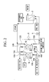
- FIG 2 components that are the same as those of the first embodiment are assigned the same reference numerals. In the following explanation, descriptions of such components similar to those of the first embodiment are appropriately omitted to avoid duplicate description.
- numerical references 1A and 1B indicate adsorption units (hereinafter appropriately referred to as "adsorption apparatus")
- numerical reference 8 indicates a steam bypass control valve
- numerical reference 9 indicates a steam injection control valve
- numerical references 10A and 10B indicate untreated gas supply valves (or gas to be treated supply valves)
- numerical references 11A and 11B indicate treated gas discharge valves
- numerical references 12A and 12B indicate steam supply valves
- numerical references 13A and 13B indicate steam discharge valves
- numerical reference 14 indicates a cooling air fan
- numerical references 15A and 15B indicate cooling air supply valves.
- the adsorption apparatus 1A (tower A) and the adsorption apparatus 1B (tower B) are similar to the adsorption apparatus 1 of the first embodiment. As shown in FIG 2, the adsorption apparatuses 1A and 1B are disposed in parallel with respect to supply paths for the untreated gas and the steam, and as described hereinbelow, alternately implement the removal of a volatile organic compound with respect to the untreated gas (gas to be treated).
- the steam bypass control valve 8 is an open/close valve which is provided between the inlet side of the steam supply valves 12A and 12B and the outlet side of the steam discharge valves 13A and 13B and which enables some of the steam to be supplied to the adsorption apparatuses 1A and 1B to directly flow into the steam injection control valve 9 without passing through the adsorption apparatuses 1A and 1B. It follows that the steam bypass control valve 8 is for supplying some of the steam discharged from the steam generating apparatus 2 to the steam injection control valve 9 with the adsorption apparatuses 1A and 1B being bypassed.
- the steam injection control valve 9 is provided between the steam bypass control valve 8 and the steam generating apparatus 2 and controls the injection quantity of steam with respect to the steam generating apparatus 2.
- the untreated gas supply valve 10A is an open/close valve that is provided at an untreated gas supply port of the adsorption apparatus 1A (tower A) and which controls supply/shutoff of untreated gas with respect to the adsorption apparatus 1A.
- the untreated gas supply valve 10B is an open/close valve that is provided at an untreated gas supply port of the adsorption apparatus 1B (tower B) and which controls supply/shutoff of untreated gas with respect to the adsorption apparatus 1B.
- the treated gas discharge valve 11 A is an open/close valve which is provided at a treated gas discharge port of the adsorption apparatus 1A and which controls the discharge/shutoff of treated gas from the adsorption apparatus 1A.
- the treated gas discharge valve 11B is an open/close valve which is provided at a treated gas discharge port of the adsorption apparatus 1B and which controls the discharge/shutoff of treated gas from the adsorption apparatus 1B.
- the steam supply valve 12A is an open/close valve which is provided at a steam supply port of the adsorption apparatus 1A and which controls the supply/shutoff of steam with respect to the adsorption apparatus 1A.
- the steam supply valve 12B is an open/close valve that is provided at a steam supply port of the adsorption apparatus 1B and which controls the supply/shutoff of steam with respect to the adsorption apparatus 1B.
- the steam discharge valve 13A is an open/close valve that is provided at a steam containing compound discharge port of the adsorption apparatus 1A and which controls discharge/shutoff of the steam containing compound from the adsorption apparatus 1A.
- the steam discharge valve 13B is an open/close valve that is provided at a steam containing compound discharge port of the adsorption apparatus 1B and which controls discharge/shutoff of the steam containing compound from the adsorption apparatus 1B.
- the cooling air fan 14 is a power source to supply cooling air to the adsorption apparatuses 1A and 1B.
- the cooling air supply valve 15A is an open/close valve which is provided between the cooling air fan 14 and the adsorption apparatus 1A and which controls supply/shutoff of cooling air with respect to the adsorption apparatus 1A.
- the cooling air supply valve 15B is an open/close valve which is provided between the cooling air fan 14 and the adsorption apparatus 1B and which controls supply/shutoff of cooling air with respect to the adsorption apparatus 1B.
- the steam which has passed through the steam bypass control valve 8 is supplied to the steam injection control valve 9.
- the quantity of steam for combustion and the quantity of steam for adsorption of the compound can be set separately from one to another.
- the combustion steam quantity is a flow rate R1
- the compound adsorption quantity is a flow rate R2 (where R1 > R2)
- R1 the difference in flow rate between R1 and R2 is supplied through the steam bypass control valve 8 to the steam injection control valve 9
- R1 ⁇ R2 the requirement for both of the combustion steam quantity and the compound adsorption quantity can be satisfied.
- R1 ⁇ R2 can be assumed. However, this is not practical because a condition where the compound adsorption steam quantity cannot entirely be treated by the gas turbine 2 is presented.
- the steam injection control valve 9 is disposed at a downstream side of the steam bypass control valve 8 in the flow direction of the steam (namely, between the steam generating apparatus 2 and the steam bypass control valve 8).
- the steam injection control valve 9 may be disposed at an upstream side of the steam bypass control valve 8 (namely, between a heat exchanger 3 and the steam bypass control valve 8).
- FIGS. 3A to 3H illustrate operating conditions "a" to "h” of the adsorption apparatuses 1A and 1B corresponding to open/close states of the steam bypass control valve 8, the untreated gas supply valves 10A and 10B, the treated gas discharge valves 11A and 11B, the steam supply valves 12A and 12B, the steam discharge valves 13A and 13B, and the cooling air supply valves 15A and 15B.
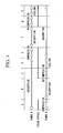
- FIG. 4 is a timing chart illustrating a transition of the operating conditions "a" to "h", in chronological order, shown in FIGS.
- the operating conditions "a” to "h” are repeatedly carried out, that is, the processes are carried out in the order of the adsorption process, the compression process, the desorption process, the decompression process, the cooling process, and back to the adsorption process.
- FIGS. 3A to 3H illustrate the open/close state of the steam bypass control valve 8.
- the steam bypass control valve 8 is, as described above, a valve which supplements the difference in flow rate between the combustion steam quantity and the compound adsorption steam quantity, but not a valve which directly controls the condition of the adsorption apparatuses 1A and 1B.
- the operating condition “a” illustrates that the adsorption apparatus 1A is “in the adsorption state” and the adsorption apparatus 1B is "in the compression state”.
- the adsorption apparatus 1A when the untreated gas supply valve 10A and the treated gas supply valve 11A are set to be in the open states and when the steam discharge valve 13A and the cooling air supply valve 15A are set to be in the closed states, the adsorption state is implemented where the untreated gas is sequentially supplied and the treated gas is sequentially discharged.
- the compression state is implemented where only the steam is sequentially supplied.
- the adsorption state is maintained.
- the state is shifted from the previous adsorption state to the compression state shown in the operating condition "a”, and then to the desorption state shown in the operation condition "b" when the pressure has become a sufficient level.
- the desorption state is then implemented where the steam is sequentially supplied and the steam containing compound is sequentially discharged.
- the state in the adsorption apparatus 1 B is shifted to the decompression state as illustrated in the operating condition "c".
- the adsorption apparatus 1B when the treated gas supply valve 11B is set to be in the open state and when the untreated gas supply valve 10B, the steam supply valve 12B, the steam discharge valve 13B and the cooling air supply valve 15B are set to be in the closed states, the compression state is implemented.
- the state in the adsorption apparatus 1B is shifted to the cooling state as illustrated in the operating condition "d".
- the cooling air supply valve 15B as well as the treated gas supply valve 11B are set to be in the open states, the cooling air is supplied until the inside of the adsorption apparatus 1B is cooled to normal temperature.
- the adsorption apparatus 1B as illustrated in the operating condition "e", when the untreated gas supply valve 10B and the treated gas discharge valve 11B are set to be in the open states and when the steam supply valve 12B, the steam discharge valve 13B, and the cooling air supply valve 15B are set to be in the closed states, the adsorption state is then implemented where the untreated gas is sequentially supplied and the treated gas is sequentially discharged.
- the compression state is then implemented where only the steam is sequentially supplied.
- the operating conditions "e” through “h” correspond to conditions formed on the assumption that the adsorption apparatus 1A and the adsorption apparatus 1B are interchanged with respect to the operating conditions "a" through “d”. A further description is therefore omitted for abbreviation.
- the adsorption apparatus 1A and the adsorption apparatus 1B alternately repeat the adsorption of the volatile organic compound from the untreated gas and the desorption of the volatile organic compound from the adsorbent. Further, the adsorption of the volatile organic compound from the untreated gas, in other words, the removal of the volatile organic compound from the untreated gas is continuously carried out by shifting the conditions of the adsorption apparatus 1A and the adsorption apparatus 1B in the order of the operating conditions "a" through "h".
- the number of adsorption apparatuses is not limited to two (i.e., the adsorption apparatus 1A and the adsorption apparatus 1B).
- the untreated gas may be continuously processed.
- FIG. 5 is a system structural view illustrating a volatile organic compound processing system according to the third embodiment. Note that, components that are the same as those of the volatile organic compound processing systems according to the first and second embodiments are assigned the same reference numerals.
- the dehumidifying tower 16 is a tower where the untreated gas is dehumidified by means of gas/liquid contact with cold water.
- the dehumidifying tower 16 is structured such that untreated gas is supplied from below and the untreated gas is concurrently discharged from above and that cold water is sprinkled from above to below. Accordingly, the untreated gas is cooled by gas-liquid contact with the cold water such that steam contained in the untreated gas is condensed and absorbed in the cold water. As a result, the untreated gas is dehumidified.
- the cooling apparatus 17 is an apparatus where the water discharged from a bottom of the dehumidifying tower 16 is cooled and is supplied to the dehumidifying tower 16 as the aforesaid cold water.
- the dehumidifying tower 16 and the cooling apparatus 17 constitute the dehumidifier of the present embodiment.
- the concentrator 18 concentrates the volatile organic compound contained in the untreated gas (the gas dehumidified) discharged from the dehumidifying tower 16 and discharges this to the cooling apparatus 20. More specifically, in the concentrator 18, the untreated gas is passed through powdered activated carbon in order to desorb and remove the volatile organic compound, and then discharged as treated gas, and at the same time, the volatile organic compound which has been adsorbed in the activated carbon is desorbed from the activated carbon by the use of the discharge gas. As a result, the discharge gas containing concentrated volatile organic compound is discharged as new gas to be treated (or new untreated gas).
- the discharge gas discharged from the steam generating apparatus 2 is high temperature gas of around 100°C. The volatile organic compound is desorbed from the activated carbon by means of this high temperature discharge gas.
- the fan 19 is provided to forcibly discharge the aforesaid treated gas from the concentrator 18.
- the cooling apparatus 20 cools the new untreated gas (i.e., the new gas to be treated) and then supplies this to the untreated gas supply valves 10A and 10B.
- the new untreated gas is gas that contains the volatile organic compound concentrated in the discharge gas discharged from the steam generating apparatus 2. Therefore, this is high temperature gas close to 100°C.
- the cooling apparatus 20 is provided to cool this untreated gas possessing high temperature to a temperature suitable for treatment in the adsorption apparatus 1A and the adsorption apparatus 1B.
- the untreated gas is pre-processed by the dehumidifier 16 including the dehumidifying tower 16 and the cooling apparatus 17, and the concentrator 18.
- the untreated gas is subjected to a dehumidifying processing and a concentration processing.
- the untreated gas is subjected to a main processing (i.e., removal of the volatile organic compound) by the adsorption apparatus 1A and the adsorption apparatus 1B.
- the new untreated gas containing the volatile organic compound whose concentration is higher than that of the aforesaid first and second embodiments is processed. Accordingly, it is possible to improve treatment efficiency.
- FIG. 4 illustrates the sequence where the adsorption processing is carried out throughout the operating conditions "a" to “d” by the adsorption apparatus 1A on the one hand and the sequence where the adsorption processing is carried out throughout the operating conditions "e” to “h” by the adsorption apparatus 1B on the other hand.
- the present third embodiment by carrying out the pre-processing, it is possible for the time necessary for the adsorption processing to be shortened. Hence, the treatment efficiency for the untreated gas can correspondingly be improved.
- either one of the dehumidifying processing and the concentration processing can be adopted. If the steam in the untreated gas is removed therefrom by the dehumidifying processing, the concentration of the volatile organic compound in the untreated gas is significantly increased, correspondingly. Accordingly, even if the pre-processing is composed of only the humidifying processing, it is also possible to improve the treatment efficiency of the untreated gas. Whereas only the concentration processing significantly increases the concentration of the volatile organic compound, it is equally possible to improve the treatment efficiency of the untreated gas.
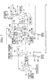
- the present volatile organic compound processing system is structured such that a fan 21, hot gas supply valves 22A and 22B, and hot gas discharge valves 23A and 23B are added to the volatile organic compound processing system according to the aforesaid third embodiment.
- the fan 21 supplies to the hot gas supply valves 22A and 22B discharge gas (hot gas) which has been discharged from the steam generating apparatus 2.
- the hot gas supply valve 22A is provided between the fan 21 and a discharge gas supply port of the adsorption apparatus 1A, and implements supply/shutoff of the discharge gas with respect to the adsorption apparatus 1A.
- the hot gas supply valve 22B is provided between the fan 21 and a discharge gas supply port of the adsorption apparatus 1B, and implements supply/shutoff of the discharge gas with respect to the adsorption apparatus 1B.
- the hot gas discharge valve 23A is provided between a discharge gas discharge port of the adsorption apparatus 1A and an untreated gas supply port of the cooling apparatus 20, and implements supply/shutoff of the discharge gas discharged from the adsorption apparatus 1A (and/or the adsorption apparatus 1B) with respect to the untreated gas supply port of the cooling apparatus 20.
- the hot gas discharge valve 23B is provided between a discharge gas discharge port of the adsorption apparatus 1B and the untreated gas supply port of the cooling apparatus 20, and implements supply/shutoff of the discharge gas discharged from the adsorption apparatus 1B (and/or the adsorption apparatus 1A) with respect to the untreated gas supply port of the cooling apparatus 20.
- Adsorption apparatuses 1A and 1B are those such as illustrated in FIGS. 3A to 3H and described in the second embodiment mentioned above.
- the adsorption apparatuses 1A and 1B which are under normal temperature conditions, some of the steam for compression is condensed and then becomes drain water. It is probable that, in this drain water, the volatile organic compound, which has been adsorbed in the adsorbent, is contained or dissolved, although the quantity is likely very small.
- the present embodied volatile organic compound processing system provides a solution by means of which such inconveniences as above are resolved or settled.
- a heating process is provided between the adsorption process and the compression process as illustrated in FIGS. 3A to 3H and FIG. 4, and is carried out by the use of the aforesaid fan 21, the hot gas supply valves 22A and 22B, the hot gas discharge valves 23A and 23B, and discharge gas discharged from the steam generating apparatus 2.
- the same or a similar heating process is carried out in every one of the adsorption apparatuses 1A and 1B.
- a description will be given of the adsorption apparatus 1B, for the convenience of explanation.
- the adsorption process in which the untreated gas is supplied to the adsorption apparatus 1B and the treated gas is discharged is completed, only the hot gas supply valve 22B and the hot gas discharge valve 23B are opened. Due to this, the discharge gas discharged from the fan 21 is supplied to the adsorption apparatus 1 B whereby the inside thereof is heated.
- This discharge gas has a temperature of around 100°C as described above, and therefore, it is possible to heat the inside of the adsorption apparatus 1B to a sufficient level such that condensation of the steam does not occur.
- the drain water may be supplied to the discharge gas discharge port of the steam generator 3, and in turn evaporated and discharged into the atmosphere. Because the water quantity of the drain water is not so substantial, it is possible to sufficiently evaporate the drain water by supplying it to the discharge gas discharge port of the steam generating apparatus 2.
- the present volatile organic compound processing system corresponds to a structure in which the steam generating apparatus 2 is disposed and separated far apart from other apparatuses, and then corresponds to a modified example of the aforesaid third and fourth embodiments.
- the discharge gas discharged from the steam generating apparatus 2 is utilized as a heat source in order to concentrate the untreated gas in the concentrator 18.
- the discharge gas discharged from the steam generating apparatus 2 is utilized as a heat source in order to control generation of the drain water in the adsorption apparatuses 1A and 1B.
- the present volatile organic compound processing system unlike the structure of the aforesaid fourth embodiment, air, instead of the discharge gas, is supplied to the fan 21, and air, instead of the discharge gas, is supplied from a fan 24 to the concentrator 18. Further, in the present system, the discharge air from the fan 21 is heated by a first heating apparatus comprised of heat exchangers 25 and 26 and a pump 27 on the one hand, and discharge air from the fan 24 is heated by a second heating apparatus comprised of heat exchangers 28 and 29 and a pump 30 on the other hand.
- the heat exchanger 25 is disposed in the vicinity of the discharge gas discharge port of the steam generating apparatus 2 and carries out heat exchange between the discharge gas discharged from the fan 21 and a predetermined heat transfer medium.
- the heat exchanger 26 is disposed in the vicinity of an air discharge port of the fan 21 and carries out heat exchange between the air discharged from the fan 21 and the aforesaid heat transfer medium.
- the pump 27 is disposed on the midway of a heat transfer medium circulation path provided between the heat exchanger 25 and the heat exchanger 26 and carries out circulation of the heat transfer medium between the heat exchanger 25 and the heat exchanger 26.
- the heat exchanger 28 is disposed in the vicinity of the discharge gas discharge port of the steam generating apparatus 2 and carries out heat exchange between the discharge gas and a predetermined heat transfer medium.
- the heat exchanger 29 is disposed in the vicinity of an air discharge port of the fan 24 and carries out heat exchange between the air discharged from the fan 24 and the heat transfer medium.
- the pump 30 is disposed on the midway along a heat transfer medium circulation path provided between the heat exchanger 28 and the heat exchanger 29 and carries out circulation of the heat transfer medium between the heat exchanger 28 and the heat exchanger 29.
- the discharge gas discharged from the steam generating apparatus 2 is not directly supplied to the concentrator 18 and/or the adsorption apparatuses 1A and 1B, and instead, by the use of the first and second heating apparatuses, heat of the discharge gas is transferred to the air discharged from the fans 21 and 24 to thereby heat the air and render the heated air, and thereafter, this heated air as hot gas is supplied to the concentrator 18 and the adsorption apparatuses 1A and 1B.
Landscapes
- Chemical & Material Sciences (AREA)
- Engineering & Computer Science (AREA)
- Analytical Chemistry (AREA)
- General Chemical & Material Sciences (AREA)
- Oil, Petroleum & Natural Gas (AREA)
- Chemical Kinetics & Catalysis (AREA)
- Health & Medical Sciences (AREA)
- Biomedical Technology (AREA)
- Environmental & Geological Engineering (AREA)
- Treating Waste Gases (AREA)
- Separation Of Gases By Adsorption (AREA)
- Incineration Of Waste (AREA)
Applications Claiming Priority (1)
| Application Number | Priority Date | Filing Date | Title |
|---|---|---|---|
| JP2006045074A JP3956996B1 (ja) | 2006-02-22 | 2006-02-22 | 揮発性有機化合物処理方法及び揮発性有機化合物処理システム |
Publications (1)
| Publication Number | Publication Date |
|---|---|
| EP1825902A1 true EP1825902A1 (de) | 2007-08-29 |
Family
ID=38093425
Family Applications (1)
| Application Number | Title | Priority Date | Filing Date |
|---|---|---|---|
| EP07250706A Withdrawn EP1825902A1 (de) | 2006-02-22 | 2007-02-20 | Verfahren zur Verarbeitung von flüchtigen organischen Verbindungen und System zur Verarbeitung von flüchtigen organischen Verbindungen |
Country Status (8)
| Country | Link |
|---|---|
| US (1) | US7914608B2 (de) |
| EP (1) | EP1825902A1 (de) |
| JP (1) | JP3956996B1 (de) |
| KR (1) | KR100860868B1 (de) |
| CN (1) | CN100565010C (de) |
| CA (1) | CA2578895C (de) |
| NO (1) | NO20070967L (de) |
| RU (1) | RU2381053C2 (de) |
Families Citing this family (12)
| Publication number | Priority date | Publication date | Assignee | Title |
|---|---|---|---|---|
| WO2007004426A1 (ja) * | 2005-07-04 | 2007-01-11 | Mitsubishi Electric Corporation | 揮発性有機化合物処理装置および揮発性有機化合物の処理方法 |
| JP5262236B2 (ja) * | 2008-03-28 | 2013-08-14 | 株式会社Ihi | 揮発性有機化合物処理システム及び揮発性有機化合物の処理方法 |
| JP5359002B2 (ja) * | 2008-03-28 | 2013-12-04 | 株式会社Ihi | 揮発性有機化合物処理システム |
| JP5024157B2 (ja) * | 2008-03-31 | 2012-09-12 | 株式会社Ihi | 揮発性有機化合物処理システム及び揮発性有機化合物の処理方法 |
| JP2009240880A (ja) * | 2008-03-31 | 2009-10-22 | Ihi Corp | 揮発性有機化合物処理システム |
| JP5355370B2 (ja) * | 2009-08-28 | 2013-11-27 | 富士フイルム株式会社 | 乾燥気体の再生方法及び設備 |
| JP5638262B2 (ja) | 2010-02-23 | 2014-12-10 | 三菱重工業株式会社 | Co2回収装置およびco2回収方法 |
| JP5113207B2 (ja) * | 2010-03-30 | 2013-01-09 | 株式会社栗本鐵工所 | 揮発性有機化合物処理装置の運用方法 |
| US20120267310A1 (en) * | 2011-04-21 | 2012-10-25 | Polizzotti David M | E-beam technology for water treatment |
| JP5835662B2 (ja) * | 2011-10-18 | 2015-12-24 | 株式会社栗本鐵工所 | 揮発性有機化合物処理装置の制御方法 |
| WO2014080984A1 (ja) | 2012-11-22 | 2014-05-30 | Uji Shigekazu | 揮発性有機化合物回収装置 |
| CN108870420A (zh) * | 2018-07-17 | 2018-11-23 | 中石化(洛阳)科技有限公司 | 一种煤化工企业可挥发性有机物的处理方法 |
Citations (7)
| Publication number | Priority date | Publication date | Assignee | Title |
|---|---|---|---|---|
| DE2847714A1 (de) * | 1978-11-03 | 1980-05-08 | Metallgesellschaft Ag | Verfahren zum regenerieren eines feststoffadsorbers |
| DE3423169A1 (de) * | 1983-06-24 | 1985-01-10 | Magyar Asványolaj és Földgáz Kisérleti Intézet, Veszprém | Verfahren zur gewinnung von organischen substanzen aus gasen durch adsorption |
| JPS6186928A (ja) * | 1984-10-05 | 1986-05-02 | Mitsubishi Heavy Ind Ltd | 有機溶剤含有排気ガスの処理方法 |
| JPS6186927A (ja) * | 1984-10-02 | 1986-05-02 | Mitsubishi Heavy Ind Ltd | 溶剤含有排ガスの処理方法 |
| JPH01231924A (ja) * | 1988-03-14 | 1989-09-18 | Mitsubishi Heavy Ind Ltd | 溶剤ガス処理方法 |
| JP2000000425A (ja) * | 1998-06-12 | 2000-01-07 | Toyobo Co Ltd | 低濃度有機溶剤ガスの処理方法及び処理装置 |
| EP1788222A1 (de) * | 2004-08-19 | 2007-05-23 | Ishikawajima-Harima Heavy Industries Co., Ltd. | Verfahren zur behandlung einer flüchtigen organischen verbindung mit einer gasturbine und system zur behandlung einer flüchtigen organischen verbindung |
Family Cites Families (20)
| Publication number | Priority date | Publication date | Assignee | Title |
|---|---|---|---|---|
| SU16638A1 (ru) | 1926-06-11 | 1930-10-31 | изыскания и эксплоатации нефтеносных земель Общество | Способ отгонки поглощенных адсорбентом газов и паров |
| SU587961A1 (ru) | 1974-12-08 | 1978-01-15 | Shelygin Aleksandr L | Способ регенерации адсорбентов |
| JPS6010772B2 (ja) | 1977-10-24 | 1985-03-20 | 東洋紡績株式会社 | 低濃度溶剤含有ガスの回収方法 |
| SU931215A1 (ru) | 1978-01-30 | 1982-05-30 | Специальное Конструкторское Бюро По Синтетической Изоляции | Способ рекуперации растворителей |
| SU1020688A1 (ru) | 1981-09-10 | 1983-05-30 | Специальное Конструкторское Бюро По Синтетической Изоляции | Котельна установка |
| SU1286252A1 (ru) | 1985-05-23 | 1987-01-30 | Рижское Отделение Всесоюзного Научно-Исследовательского И Проектно-Технологического Института Электроизоляционных Материалов И Фольгированных Диэлектриков | Способ рекуперации органического растворител из паровоздушной смеси |
| US4919692A (en) * | 1988-12-19 | 1990-04-24 | Vara International, Inc. | Process for removing solvents and other contaminants from an inlet solvent laden air path |
| DE4003668A1 (de) | 1989-02-20 | 1990-08-23 | Siemens Ag | Verfahren und vorrichtung zur entfernung von kohlenwasserstoffen, kohlenwasserstoffverbindungen und chlorierten kohlenwasserstoffen aus abluft |
| US5256208A (en) * | 1991-10-01 | 1993-10-26 | Rafson Harold J | Process for removing volatile contaminants from granular materials |
| US5281257A (en) * | 1992-12-11 | 1994-01-25 | Purus Inc. | System for increasing efficiency of vapor phase pollutant removal with on-site regeneration and pollutant recovery |
| US6372018B1 (en) * | 2000-03-14 | 2002-04-16 | Harold R. Cowles | VOC removal or destruction system |
| DE10016079A1 (de) * | 2000-03-31 | 2001-10-04 | Alstom Power Nv | Verfahren zum Entfernen von Kohlendioxid aus dem Abgas einer Gasturbinenanlage sowie Vorrichtung zur Durchführung des Verfahrens |
| KR100436449B1 (ko) * | 2001-05-09 | 2004-06-22 | 한복열 | 도장부스용 휘발성유기화합물 흡탈착장치 및 과포화증기를이용한 활성탄필터의 재생방법 |
| KR20010099169A (ko) | 2001-09-07 | 2001-11-09 | 여호섭 | 도장부스의 휘발성유기화합물 흡착제와 그의 재생방법 |
| JP2003322324A (ja) | 2002-04-26 | 2003-11-14 | Meidensha Corp | 有害物質の処理装置および処理方法 |
| JP3924209B2 (ja) | 2002-07-03 | 2007-06-06 | 新潟原動機株式会社 | 有機成分含有空気および廃液の処理装置 |
| JP2004184003A (ja) | 2002-12-04 | 2004-07-02 | Niigata Power Systems Co Ltd | ガスタービンを利用した脱臭・廃液処理方法及びその装置 |
| US7833494B2 (en) * | 2003-01-29 | 2010-11-16 | Siemens Aktiengesellschaft | Method and apparatus for the destruction of volatile organic compounds |
| US20050109207A1 (en) * | 2003-11-24 | 2005-05-26 | Olander W. K. | Method and apparatus for the recovery of volatile organic compounds and concentration thereof |
| US7063026B1 (en) * | 2004-12-10 | 2006-06-20 | Masao Kanai | Waste carbonizing and energy utilizing system |
-
2006
- 2006-02-22 JP JP2006045074A patent/JP3956996B1/ja not_active Expired - Lifetime
-
2007
- 2007-02-17 CN CNB2007101097184A patent/CN100565010C/zh not_active Expired - Fee Related
- 2007-02-19 CA CA2578895A patent/CA2578895C/en active Active
- 2007-02-19 RU RU2007106194/15A patent/RU2381053C2/ru active
- 2007-02-20 US US11/676,964 patent/US7914608B2/en not_active Expired - Fee Related
- 2007-02-20 KR KR1020070017171A patent/KR100860868B1/ko not_active Expired - Fee Related
- 2007-02-20 EP EP07250706A patent/EP1825902A1/de not_active Withdrawn
- 2007-02-20 NO NO20070967A patent/NO20070967L/no not_active Application Discontinuation
Patent Citations (7)
| Publication number | Priority date | Publication date | Assignee | Title |
|---|---|---|---|---|
| DE2847714A1 (de) * | 1978-11-03 | 1980-05-08 | Metallgesellschaft Ag | Verfahren zum regenerieren eines feststoffadsorbers |
| DE3423169A1 (de) * | 1983-06-24 | 1985-01-10 | Magyar Asványolaj és Földgáz Kisérleti Intézet, Veszprém | Verfahren zur gewinnung von organischen substanzen aus gasen durch adsorption |
| JPS6186927A (ja) * | 1984-10-02 | 1986-05-02 | Mitsubishi Heavy Ind Ltd | 溶剤含有排ガスの処理方法 |
| JPS6186928A (ja) * | 1984-10-05 | 1986-05-02 | Mitsubishi Heavy Ind Ltd | 有機溶剤含有排気ガスの処理方法 |
| JPH01231924A (ja) * | 1988-03-14 | 1989-09-18 | Mitsubishi Heavy Ind Ltd | 溶剤ガス処理方法 |
| JP2000000425A (ja) * | 1998-06-12 | 2000-01-07 | Toyobo Co Ltd | 低濃度有機溶剤ガスの処理方法及び処理装置 |
| EP1788222A1 (de) * | 2004-08-19 | 2007-05-23 | Ishikawajima-Harima Heavy Industries Co., Ltd. | Verfahren zur behandlung einer flüchtigen organischen verbindung mit einer gasturbine und system zur behandlung einer flüchtigen organischen verbindung |
Also Published As
| Publication number | Publication date |
|---|---|
| RU2381053C2 (ru) | 2010-02-10 |
| CN100565010C (zh) | 2009-12-02 |
| JP2007222736A (ja) | 2007-09-06 |
| KR20070085147A (ko) | 2007-08-27 |
| US20070193447A1 (en) | 2007-08-23 |
| JP3956996B1 (ja) | 2007-08-08 |
| US7914608B2 (en) | 2011-03-29 |
| KR100860868B1 (ko) | 2008-09-29 |
| NO20070967L (no) | 2007-08-23 |
| CA2578895C (en) | 2010-11-16 |
| CN101055084A (zh) | 2007-10-17 |
| RU2007106194A (ru) | 2008-08-27 |
| CA2578895A1 (en) | 2007-08-22 |
Similar Documents
| Publication | Publication Date | Title |
|---|---|---|
| US7914608B2 (en) | Method of processing volatile organic compound and system for processing volatile organic compound | |
| EP1788222B1 (de) | Verfahren zur behandlung flüchtigen organischen verbindungen mit einer gasturbine und system zur behandlung von flüchtigen organischen verbindungen | |
| US7678179B2 (en) | Method of processing volatile organic compound by using gas turbine and processing system of volatile organic compound | |
| CA2592855C (en) | Method of processing volatile organic compound, adsorption and desorption apparatus, and system for processing volatile organic compound | |
| JP2010112377A (ja) | ガスタービンシステム内の腐食を低減するためのシステム及び方法 | |
| KR20150123352A (ko) | 휘발성 유기화합물 처리장치 및 방법 | |
| CN105854434A (zh) | VOCs资源化处理系统 | |
| JP4702453B2 (ja) | 揮発性有機化合物含有排ガス処理システム | |
| JP6008096B2 (ja) | 揮発性有機化合物回収装置及び揮発性有機化合物回収方法 | |
| TWM624336U (zh) | 汽電共生系統 | |
| JP2005164205A (ja) | 燃焼設備の燃焼方法とその設備 |
Legal Events
| Date | Code | Title | Description |
|---|---|---|---|
| PUAI | Public reference made under article 153(3) epc to a published international application that has entered the european phase |
Free format text: ORIGINAL CODE: 0009012 |
|
| AK | Designated contracting states |
Kind code of ref document: A1 Designated state(s): AT BE BG CH CY CZ DE DK EE ES FI FR GB GR HU IE IS IT LI LT LU LV MC NL PL PT RO SE SI SK TR |
|
| AX | Request for extension of the european patent |
Extension state: AL BA HR MK YU |
|
| RAP1 | Party data changed (applicant data changed or rights of an application transferred) |
Owner name: IHI CORPORATION |
|
| 17P | Request for examination filed |
Effective date: 20071025 |
|
| 17Q | First examination report despatched |
Effective date: 20071213 |
|
| AKX | Designation fees paid |
Designated state(s): DE FR GB IT SE |
|
| STAA | Information on the status of an ep patent application or granted ep patent |
Free format text: STATUS: THE APPLICATION IS DEEMED TO BE WITHDRAWN |
|
| 18D | Application deemed to be withdrawn |
Effective date: 20080424 |